EP2143891A2 - A device and method for controlling the pressure of a steam turbine of a combined cycle plant and a bypass system thereof - Google Patents
A device and method for controlling the pressure of a steam turbine of a combined cycle plant and a bypass system thereof Download PDFInfo
- Publication number
- EP2143891A2 EP2143891A2 EP08425474A EP08425474A EP2143891A2 EP 2143891 A2 EP2143891 A2 EP 2143891A2 EP 08425474 A EP08425474 A EP 08425474A EP 08425474 A EP08425474 A EP 08425474A EP 2143891 A2 EP2143891 A2 EP 2143891A2
- Authority
- EP
- European Patent Office
- Prior art keywords
- pressure
- module
- set point
- hpsp
- pressure set
- Prior art date
- Legal status (The legal status is an assumption and is not a legal conclusion. Google has not performed a legal analysis and makes no representation as to the accuracy of the status listed.)
- Granted
Links
Images



Classifications
-
- F—MECHANICAL ENGINEERING; LIGHTING; HEATING; WEAPONS; BLASTING
- F01—MACHINES OR ENGINES IN GENERAL; ENGINE PLANTS IN GENERAL; STEAM ENGINES
- F01K—STEAM ENGINE PLANTS; STEAM ACCUMULATORS; ENGINE PLANTS NOT OTHERWISE PROVIDED FOR; ENGINES USING SPECIAL WORKING FLUIDS OR CYCLES
- F01K17/00—Using steam or condensate extracted or exhausted from steam engine plant
- F01K17/02—Using steam or condensate extracted or exhausted from steam engine plant for heating purposes, e.g. industrial, domestic
- F01K17/025—Using steam or condensate extracted or exhausted from steam engine plant for heating purposes, e.g. industrial, domestic in combination with at least one gas turbine, e.g. a combustion gas turbine
-
- F—MECHANICAL ENGINEERING; LIGHTING; HEATING; WEAPONS; BLASTING
- F01—MACHINES OR ENGINES IN GENERAL; ENGINE PLANTS IN GENERAL; STEAM ENGINES
- F01K—STEAM ENGINE PLANTS; STEAM ACCUMULATORS; ENGINE PLANTS NOT OTHERWISE PROVIDED FOR; ENGINES USING SPECIAL WORKING FLUIDS OR CYCLES
- F01K13/00—General layout or general methods of operation of complete plants
- F01K13/02—Controlling, e.g. stopping or starting
-
- F—MECHANICAL ENGINEERING; LIGHTING; HEATING; WEAPONS; BLASTING
- F01—MACHINES OR ENGINES IN GENERAL; ENGINE PLANTS IN GENERAL; STEAM ENGINES
- F01K—STEAM ENGINE PLANTS; STEAM ACCUMULATORS; ENGINE PLANTS NOT OTHERWISE PROVIDED FOR; ENGINES USING SPECIAL WORKING FLUIDS OR CYCLES
- F01K7/00—Steam engine plants characterised by the use of specific types of engine; Plants or engines characterised by their use of special steam systems, cycles or processes; Control means specially adapted for such systems, cycles or processes; Use of withdrawn or exhaust steam for feed-water heating
- F01K7/16—Steam engine plants characterised by the use of specific types of engine; Plants or engines characterised by their use of special steam systems, cycles or processes; Control means specially adapted for such systems, cycles or processes; Use of withdrawn or exhaust steam for feed-water heating the engines being only of turbine type
- F01K7/18—Steam engine plants characterised by the use of specific types of engine; Plants or engines characterised by their use of special steam systems, cycles or processes; Control means specially adapted for such systems, cycles or processes; Use of withdrawn or exhaust steam for feed-water heating the engines being only of turbine type the turbine being of multiple-inlet-pressure type
- F01K7/20—Control means specially adapted therefor
-
- F—MECHANICAL ENGINEERING; LIGHTING; HEATING; WEAPONS; BLASTING
- F22—STEAM GENERATION
- F22B—METHODS OF STEAM GENERATION; STEAM BOILERS
- F22B1/00—Methods of steam generation characterised by form of heating method
- F22B1/02—Methods of steam generation characterised by form of heating method by exploitation of the heat content of hot heat carriers
- F22B1/18—Methods of steam generation characterised by form of heating method by exploitation of the heat content of hot heat carriers the heat carrier being a hot gas, e.g. waste gas such as exhaust gas of internal-combustion engines
- F22B1/1807—Methods of steam generation characterised by form of heating method by exploitation of the heat content of hot heat carriers the heat carrier being a hot gas, e.g. waste gas such as exhaust gas of internal-combustion engines using the exhaust gases of combustion engines
- F22B1/1815—Methods of steam generation characterised by form of heating method by exploitation of the heat content of hot heat carriers the heat carrier being a hot gas, e.g. waste gas such as exhaust gas of internal-combustion engines using the exhaust gases of combustion engines using the exhaust gases of gas-turbines
-
- Y—GENERAL TAGGING OF NEW TECHNOLOGICAL DEVELOPMENTS; GENERAL TAGGING OF CROSS-SECTIONAL TECHNOLOGIES SPANNING OVER SEVERAL SECTIONS OF THE IPC; TECHNICAL SUBJECTS COVERED BY FORMER USPC CROSS-REFERENCE ART COLLECTIONS [XRACs] AND DIGESTS
- Y02—TECHNOLOGIES OR APPLICATIONS FOR MITIGATION OR ADAPTATION AGAINST CLIMATE CHANGE
- Y02E—REDUCTION OF GREENHOUSE GAS [GHG] EMISSIONS, RELATED TO ENERGY GENERATION, TRANSMISSION OR DISTRIBUTION
- Y02E20/00—Combustion technologies with mitigation potential
- Y02E20/16—Combined cycle power plant [CCPP], or combined cycle gas turbine [CCGT]
Definitions
- the present invention relates to a device and method for controlling the pressure of a steam turbine of a combined cycle plant and a bypass system thereof.
- a device and method for controlling the pressure of a steam turbine of a combined cycle plant and a bypass system thereof are provided, as claimed in claims 1 and 15, respectively.
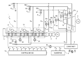
- a combined cycle plant for the production of electric energy comprises a gas turbine 2, a steam turbine 3, two alternators 5, 6, coupled to the gas turbine 2 and to the steam turbine 3 respectively, a steam generator 7, a condenser 8, an acquisition module 9 and a control device 10 associated to the steam turbine 3 and to the bypass system thereof.
- the plant may comprise a gas turbine, a steam turbine and an alternator on a same axis.
- the gas turbine 2 operates under the control of a corresponding regulator device, of known type and not shown herein.
- the exhaust fumes of the gas turbine 2 are channeled along a pipe 11 and provide a heat source for the steam generator 7.
- the steam turbine 3 comprises a high-pressure section 12, an intermediate-pressure section 13 and a low-pressure section 14.
- the steam turbine comprises the high-pressure section and an intermediate-low-pressure section.
- the steam generator 7 comprises a high-pressure element 15, an intermediate-pressure element 16 and a low-pressure element 17, each of which comprises an economizer 20, a drum 21, an evaporator 22 and a superheater 23, the operation of which is known and will not be discussed in detail.
- the economizers 20 of the high-pressure element 15 and of the intermediate-pressure element 16 receive water from corresponding feeding pumps 25, while the economizer 20 of the low-pressure element 17 receives water from a collecting tank of the condenser 8, through an extraction pump 26.
- the high-pressure element 15 feeds a high-pressure steam flow rate Q HP to the high-pressure section 12 of the steam turbine 3.
- the intermediate-pressure element 23 supplies a superheated steam flow rate Q S , which is added to the outlet flow rate Q O from the high-pressure section 12 of the steam turbine 3 to form an intermediate-pressure steam flow rate Q IP to be fed the intermediate-pressure section 13 of the steam turbine 3 through a further superheater 19.
- the low-pressure element 17 supplies the low-pressure steam flow rate Q HP to be fed to the low-pressure section 14 of the steam turbine 3.
- the discharge of the low-pressure section 14 of the steam turbine 3 is connected to the condenser 8, while the discharge of the intermediate-pressure section 13 is connected to the inlet of the low-pressure section 14.
- the steam turbine 3 is provided with a plurality of regulation valves, controlled by the control device 10, as explained in detail below, in order to regulate the pressure conditions within the cylindrical bodies 21 of the high-pressure element 15, of the intermediate-pressure element 16 and of the low-pressure element 17, as well as the flow of steam to the high-pressure section 12, to the intermediate-pressure section 13 and to the low-pressure section 14.
- the regulation valves include:
- inlet valves 27a-27c, bypass valves 28a-28c and induction valves 29a-29d are provided with corresponding regulators 30, (known per se), mutually independent and operating on valve actuating members so that the pressure upstream of each valve tends to go to a corresponding pressure set point.
- the control device 10 which will be described in detail below, generates appropriate pressure set points for the regulators 30 of each of the inlet valves 27a-27c, the bypass valves 28a-28c and the induction valves 29a-29d according to the operating conditions of the plant 1, which are detected using measurements of operating quantities and current values of status signals, supplied by the acquisition module 9.
- the pressure set points are calculated according to a so-called “sliding pressure-type" control, as will be explained in detail below.
- the control device 10 comprises a high-pressure control stage 32, an intermediate-pressure control stage 33 and a low-pressure control stage 34.
- the intermediate-pressure control stage 33 essentially works in the same manner as the high-pressure control stage 32 and thus will not be deeply discussed. It is however understood that the description regarding the high-pressure control stage 32 also applies to the intermediate-pressure control stage 33.
- Figure 3 shows a block diagram related to the high-pressure control stage 32, which comprises a supervisor module 35 and a plurality of operating modules, selectively activable by the supervisor module 35 according to the operating conditions of the plant 1.
- the operating modules comprise:
- Each operating module when activated by the supervisor module 35, supplies an inlet pressure set point P HPCV and a bypass pressure set point P HPBP , for the regulator 30 of the high-pressure inlet valve 27a and of the high-pressure bypass valve 28a, respectively.
- the operating modules actually supply an induction pressure set point P HPL for the regulator 30 of the high-pressure induction valve 29a.
- the induction pressure set point P HPL is such to keep the high-pressure induction valve 29a closed, which in practice only intervenes during the first steps of starting-up. For this reason, in figure 3 the induction pressure set point P HPL is indicated only for the first start-up module 38 and for the second start-up module 39.
- the operating conditions of the plant 1 are detected by the supervisor module 35 on the basis of measurements of a plurality of operating quantities, including the high-pressure steam flow rate Q HP at the outlet of the superheater 23 of the high-pressure element 15 of the steam generator 7 and the steam pressure upstream of the high-pressure inlet valve 27a and of the high-pressure bypass valve 28a (controlled pressure P HP ) .
- the supervisor module 35 activates the sliding pressure module 36 which applies the normal control mode, i.e. the sliding pressure control mode.
- the inlet pressure set point P HPCV is determined according to the flow rate of high-pressure steam Q HP , which indicates the current load of the gas turbine 2, so that the controlled pressure P HP follows a predetermined operating curve P HPSP (Q HP ), qualitatively illustrated by a solid line in figure 4 (the load L of the gas turbine 2 is qualitatively shown with a dotted line in figure 4 ).
- the operating curve P HPS P (Q HP ) displays a first constant segment, at a minimum value P MIN , for values of the high-pressure steam flow rate Q HP lower than a threshold Q TH which corresponds to approximately half a nominal flow rate value.
- the operating curve P HPSP (Q HP ) has a second increasing segment.
- the second segment of the operating curve P HPSP (Q HP ) is essentially linear with respect to the high-pressure steam flow rate Q HP and corresponds to the natural pressure upstream of the high-pressure inlet valve 27a, i.e. with the high-pressure inlet valve 27a fully open.
- the inlet pressure set point P HPCV is thus slightly lower than the operating curve P HPSP (Q HP ) so that the high-pressure inlet valve 27a tends to remain fully open in normal operating conditions, with the high-pressure steam flow rate Q HP higher than the threshold Q TH .
- both the inlet pressure set point P HPCV and the bypass pressure set point P HPBP follow the operating curve P HPSP (Q HP ), according to the value of the high-pressure steam flow rate Q HP .
- the sliding pressure module 36 is deactivated when the plant 1 is started up and when abnormal operating conditions occur.
- the high-pressure steam flow rate Q HP is absent when the gas turbine 2 is started.
- the pressure upstream of the high-pressure inlet valve 27a and of the high-pressure bypass valve 28a, i.e. the controlled pressure P HP may be kept at values even higher than the minimum pressure P MIN , generally according to the time elapsed between the shutdown and the restart of the gas turbine 2.
- the supervisor module 35 selectively activates the first start-up module 38 or the second start-up module 39 according to whether the controlled pressure P HP is lower than or higher than the minimum pressure P MIN , respectively.
- the start-up module 38 provides an induction set point pressure P HPL for the regulator 30 of the high-pressure induction valve 29a so as to increase the controlled pressure P HP , until the pressure control passes to the high-pressure bypass valve 28a.
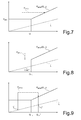
- the first start-up module 37 controls the high-pressure induction valve 29a closing and determines increasing values of the bypass pressure set point P HPBP , so that the controlled pressure P HP increases as the load L of the gas turbine 2 increases, essentially as shown in figure 5 .
- the supervisor module 35 deactivates the first start-up module 38 and selects the sliding pressure module 36.
- the supervisor module 35 activates the second start-up module 39.
- the bypass pressure set point P HPBP and the inlet pressure set point P HPCV are kept constant as the high-pressure steam load Q HP and the load L of the gas turbine 2 vary, as long as the controlled pressure P HP intercepts the operating curve P HPSP (Q HP ). More specifically, during an initial step of the starting manoeuvre, the high-pressure inlet valve 27a is closed and the control is performed by the high-pressure bypass valve 28a, with a constant bypass pressure set point P HPBP . Subsequently, the control is performed by the high-pressure inlet valve 27a, with an always constant inlet pressure set point P HPCV , while the high-pressure bypass valve 28a tends to close.
- the supervisor module 35 activates the constant pressure module 37.
- a condition which determines the activation of the constant pressure module 37 is given by invalid measurements of the high-pressure steam flow rate Q HP .
- the inlet pressure set point P HPCV is constant, regardless of the high-pressure steam flow rate Q HP and of the load L of the gas turbine 2. Furthermore, the bypass pressure set point P HPBP is equal to the inlet pressure set point P HPCV , increased by the bypass bias B BP .
- the supervisor module 35 automatically allows to return to the sliding pressure control mode by activating the first recovery module 40, the second recovery module 41 or the third recovery module 42, according to the current load L' and to a scheduled load L* of the gas turbine 2.
- the portion of energy which each operator must introduce into the network is indeed assigned on a daily basis by a governing authority; the load of the plants is scheduled over a day according to the portion which belongs to the operator.
- the supervisor module 35 is configured to accept and perform a possible request by the operator with priority. It is worth noting that after a period in which the sliding pressure control module has been excluded, upon load variations of the gas turbine 2, the controlled pressure P HP usually departs from the operating curve P HPSP (Q HP ).
- the supervisor module 35 uses the first recovery module 40.
- the inlet pressure set point P HPCV is kept constant to the initial value of the controlled pressure P HP until, with the increase of the load L of the gas turbine 2 and of the high-pressure steam flow rate Q HP , the controlled pressure P HP intercepts the operating curve P HPSP (Q HP ) again.
- the supervisor module 35 excludes the first recovery module 40 and activates the sliding pressure module 36. In this manner, as for the start up with controlled pressure P HP higher than the minimum pressure P MIN , the depressurization of the drum 21 of the high-pressure element 15 of the steam generator 7 is advantageously avoided.
- the second recovery module 41 and the third recovery module 42 are activated when the scheduled load L for the gas turbine 2 is not temporarily sufficient to reach the operating curve P HPSP (Q HP ) thus keeping constant the inlet pressure set point P HPCV .
- the second recovery module 41 is activated when the current load L' of the gas turbine 2 is close to the scheduled load L*.
- the second recovery module 41 reduces the inlet pressure set point P HPCV for depressurizing the drum 21 of the high-pressure element 15 of the steam generator 7 until the controlled pressure P HP intercepts the operating curve P HPSP (Q HP ), regardless of the value of the high-pressure steam flow rate Q HP with respect to the threshold Q TH .
- the supervisor module 35 activates the sliding pressure module 36 again.
- the third recovery module 42 is activated and performs a partial depressurization ( figure 9 ). Specifically, the third recovery module 42 keeps the inlet pressure set point P HPCV constant, until the current load L' reaches the scheduled load L*, and thus reduces it until the operating curve P HPSP (Q HP ) is intercepted.
- the supervisor module activates the sliding pressure module 36 again when the described condition occurs.
- the supervisor module 35 activates the controlled shutdown module 43 in case of controlled (or scheduled) shutdown of the gas turbine 2.
- the load L of the gas turbine 2 and thus also of the high-pressure steam flow rate Q HP , is gradually reduced to shutdown.
- the controlled shutdown conditions of the gas turbine 2 are recognized by the supervisor module 35, which detects a specific status signal at a value indicating the occurring shutdown.
- the supervisor module activates the load rejection module 44.
- load rejection conditions the gas turbine 2 remains in operation, but is disconnected from the electric network and works in speed control, feeding only the plant auxiliaries. Accordingly, the load is minimum.
- the inlet pressure set point P HPCV and, subsequently, the bypass pressure set point P HPBP are determined on the basis of the operating curve P HPSP (Q HP ), which ensures the depressurization of the high-pressure element 15 of the steam generator 7. Possible different requests by an operator are ignored. In this manner, the condition of high pressure in the drum 21 of the high-pressure element 15 is avoided in conjunction with a low temperature of the exhaust fumes of the gas turbine 2, which operates with a reduced load L.
- the described condition is particularly detrimental in the case of load rejection, because it can be continued for an undetermined, even very long, time.
- controlled shutdown module 43 and the load rejection module 44 lead the controlled pressure below a first threshold P TH1 , in case of shutdown of the gas turbine 2, and below a second threshold P TH2 , lower than the first threshold P TH1 , in case of load rejection, respectively.
- the blockage module 45 is automatically selected in case of blockage of the gas turbine 2. Such a condition is recognized on the basis of a flame presence signal of the gas turbine 2.
- the blockage module 45 sets the inlet pressure set point P HPCV by tracking the current value of the pressure measured upstream of the high-pressure inlet valve 27a and of the high-pressure bypass valve 28a, which in this condition may not be controlled. Furthermore, the bypass pressure set point P HPBP is increased by a bypass bias B BP to determine the closing of the bypass valve 28a and thus to preserve the pressure of the high-pressure element 15 of the steam generator 7 at the highest value until the next restart of the plant 1.
- the intermediate-pressure control stage 33 comprises a supervisor module 35' and a plurality of operating modules including: a sliding pressure module 36'; a constant pressure module 37'; a first start-up module 38'; a second start-up module 39'; a first sliding pressure recovery module 40'; a second sliding pressure recovery module 41'; a third sliding pressure recovery module 42'; a controlled shutdown module 43'; a load rejection module 44'; and a blockage module 45'.
- Each operating module when activated by the supervisor module 35', provides an inlet pressure set point P IPCV and a bypass pressure set point P IPBP , for the regulator 30 of the intermediate-pressure inlet valve 27a and for the intermediate-pressure bypass valve 28b, respectively. Furthermore, the operating modules actually provide an induction pressure set point P IPL for the regulators 30 of the intermediate-pressure induction valves 29b1, 29b2.
- the intermediate-pressure control stage 13 also works on the basis of a sliding pressure-type control, using an operating curve P IPSP (Q HP ) similar to the operating curve P HPSP (Q HP ) of the high-pressure control stage 12.
- the operating curve P IPSP (Q HP ) is also expressed according to the high-pressure steam flow rate Q HP .
- the low-pressure control stage 34 further generates pressure set points for the regulators 30 of the low-pressure inlet valve 27c, the low-pressure bypass valve 28c and the low-pressure induction valve 29c.
- the pressure set points for the regulators of the valves 27c, 28c are generated according to a "constant pressure-type" control.
- the described control device allows to advantageously increase the level of automation in controlling the combined cycle plants, specifically with regards to steam turbines.
- the control device is indeed able to recognize plant operating conditions on the basis of detected parameters and status signals and to consequently select the most appropriate operating mode, in terms of both efficiency and safety.
Landscapes
- Engineering & Computer Science (AREA)
- Chemical & Material Sciences (AREA)
- Combustion & Propulsion (AREA)
- Mechanical Engineering (AREA)
- General Engineering & Computer Science (AREA)
- Life Sciences & Earth Sciences (AREA)
- Sustainable Development (AREA)
- Sustainable Energy (AREA)
- Physics & Mathematics (AREA)
- Thermal Sciences (AREA)
- Control Of Turbines (AREA)
- Engine Equipment That Uses Special Cycles (AREA)
Abstract
Description
- The present invention relates to a device and method for controlling the pressure of a steam turbine of a combined cycle plant and a bypass system thereof.
- It is known that steam turbine control in combined cycle plants is complex and fairy problematic, because it has to cope with several events in both normal operating conditions and in transient conditions.
- Firstly, it should be considered that, in combined cycle plants, steam turbine operation closely depends on the operating conditions of the gas turbine, because the exhaust gases of the latter provide the thermal energy required for the production of steam. The flow of exhaust gas of the gas turbine, which is directly related to load, thus determines the operating limits of the steam turbine.
- Furthermore, it should be considered that several independent suppliers are present in modern electric energy distribution networks. Network condition control, previously entrusted to a single entity, is now the responsibility of all suppliers and the plants must comply with often very strict standards. Broad flexibility is required in all cases with regard to intervention capacities for both network adjustment and to respond to extremely varying load requests.
- For example, plant shutdown and consequent restarting have become relatively frequent events. Similarly, load rejection conditions of the gas turbine, in which the generator coupled to the gas turbine itself remains isolated from the network, are not rare. In this case, the gas turbine runs at minimum load and the steam turbine must be taken to a compatible operating condition.
- The currently available pressure control apparatuses of steam turbines are not satisfactory because they are still quite complex and require a considerable effort and preparation by the powerplant operators.
- Precisely for the relevance of the human factor, this firstly implies higher error risks. Furthermore, the installation, testing and maintenance costs and times are also very high and require complex, difficult procedures.
- It is thus an object of the present invention to provide a device and method for controlling the pressure of a steam turbine and the bypass system thereof in a combined cycle plant, which allows to overcome the described limitations.
- According to the present invention, a device and method for controlling the pressure of a steam turbine of a combined cycle plant and a bypass system thereof are provided, as claimed in
claims - The present invention will now be described with reference to the accompanying drawings, which illustrate a non-limitative embodiment thereof, in which:
-
figure 1 is a simplified block diagram of a combined cycle plant; -
figure 2 is a simplified block diagram of the control device in accordance with an embodiment of the present invention, incorporated in the combined cycle plant infigure 1 ; -
figure 3 is a detailed block diagram of a first element of the device infigure 2 ; -
figures 4-10 are charts showing quantities related to the device infigure 1 ; and -
figure 11 is a detailed block diagram of a second element of the device infigure 2 . - As shown in
figure 1 , a combined cycle plant for the production of electric energy comprises agas turbine 2, asteam turbine 3, twoalternators 5, 6, coupled to thegas turbine 2 and to thesteam turbine 3 respectively, a steam generator 7, a condenser 8, an acquisition module 9 and acontrol device 10 associated to thesteam turbine 3 and to the bypass system thereof. Alternatively, the plant may comprise a gas turbine, a steam turbine and an alternator on a same axis. - The
gas turbine 2 operates under the control of a corresponding regulator device, of known type and not shown herein. The exhaust fumes of thegas turbine 2 are channeled along apipe 11 and provide a heat source for the steam generator 7. - The
steam turbine 3 comprises a high-pressure section 12, an intermediate-pressure section 13 and a low-pressure section 14. In a different embodiment (not shown), the steam turbine comprises the high-pressure section and an intermediate-low-pressure section. - The steam generator 7 comprises a high-
pressure element 15, an intermediate-pressure element 16 and a low-pressure element 17, each of which comprises aneconomizer 20, adrum 21, anevaporator 22 and asuperheater 23, the operation of which is known and will not be discussed in detail. - The
economizers 20 of the high-pressure element 15 and of the intermediate-pressure element 16 receive water fromcorresponding feeding pumps 25, while theeconomizer 20 of the low-pressure element 17 receives water from a collecting tank of the condenser 8, through anextraction pump 26. - The high-
pressure element 15 feeds a high-pressure steam flow rate QHP to the high-pressure section 12 of thesteam turbine 3. - The intermediate-
pressure element 23 supplies a superheated steam flow rate QS, which is added to the outlet flow rate QO from the high-pressure section 12 of thesteam turbine 3 to form an intermediate-pressure steam flow rate QIP to be fed the intermediate-pressure section 13 of thesteam turbine 3 through a further superheater 19. - The low-
pressure element 17 supplies the low-pressure steam flow rate QHP to be fed to the low-pressure section 14 of thesteam turbine 3. - The discharge of the low-
pressure section 14 of thesteam turbine 3 is connected to the condenser 8, while the discharge of the intermediate-pressure section 13 is connected to the inlet of the low-pressure section 14. - The
steam turbine 3 is provided with a plurality of regulation valves, controlled by thecontrol device 10, as explained in detail below, in order to regulate the pressure conditions within thecylindrical bodies 21 of the high-pressure element 15, of the intermediate-pressure element 16 and of the low-pressure element 17, as well as the flow of steam to the high-pressure section 12, to the intermediate-pressure section 13 and to the low-pressure section 14. The regulation valves include: - a high-
pressure inlet valve 27a, an intermediate-pressure inlet valve 27b and a low-pressure inlet valve 27c, for regulating the steam flow entering the high-pressure section 12, the intermediate-pressure section 13 and the low-pressure section 14 of thesteam turbine 3, respectively; - a high-
pressure bypass valve 28a, an intermediate-pressure bypass valve 28b and a low-pressure bypass valve 28c, parallelly connected to the high-pressure section 12, to the intermediate-pressure section 13 and to the low-pressure section 14 of thesteam turbine 3, respectively (thebypass valves 28a-28c form the steam turbine bypass system 3); and - a high-
pressure induction valve 29a, arranged downstream of thesuperheater 23 of the high-pressure element 15 of the steam generator 7, two intermediate-pressure induction valves 29b1, 29b2, arranged downstream of thesuperheater 23 of the intermediate-pressure element 16 and downstream of the re-superheater 19 respectively, and a low-pressure induction valve 29c, arranged downstream of thesuperheater 23 of the low-pressure element 17. - All
inlet valves 27a-27c,bypass valves 28a-28c andinduction valves 29a-29d are provided withcorresponding regulators 30, (known per se), mutually independent and operating on valve actuating members so that the pressure upstream of each valve tends to go to a corresponding pressure set point. - The
control device 10, which will be described in detail below, generates appropriate pressure set points for theregulators 30 of each of theinlet valves 27a-27c, thebypass valves 28a-28c and theinduction valves 29a-29d according to the operating conditions of theplant 1, which are detected using measurements of operating quantities and current values of status signals, supplied by the acquisition module 9. The pressure set points are calculated according to a so-called "sliding pressure-type" control, as will be explained in detail below. - With reference to
figure 2 , thecontrol device 10 comprises a high-pressure control stage 32, an intermediate-pressure control stage 33 and a low-pressure control stage 34. The intermediate-pressure control stage 33 essentially works in the same manner as the high-pressure control stage 32 and thus will not be deeply discussed. It is however understood that the description regarding the high-pressure control stage 32 also applies to the intermediate-pressure control stage 33. -
Figure 3 shows a block diagram related to the high-pressure control stage 32, which comprises asupervisor module 35 and a plurality of operating modules, selectively activable by thesupervisor module 35 according to the operating conditions of theplant 1. - In the embodiment described herein, the operating modules comprise:
- a sliding
pressure module 36; - a
constant pressure module 37; - a first start-
up module 38; - a second start-
up module 39; - a
first recovery module 40; - a
second recovery module 41; - a
third recovery module 42; - a controlled shutdown module 43;
- a
load rejection module 44; and - a
blockage module 45. - Each operating module, when activated by the
supervisor module 35, supplies an inlet pressure set point PHPCV and a bypass pressure set point PHPBP, for theregulator 30 of the high-pressure inlet valve 27a and of the high-pressure bypass valve 28a, respectively. The operating modules actually supply an induction pressure set point PHPL for theregulator 30 of the high-pressure induction valve 29a. Normally, however, the induction pressure set point PHPL is such to keep the high-pressure induction valve 29a closed, which in practice only intervenes during the first steps of starting-up. For this reason, infigure 3 the induction pressure set point PHPL is indicated only for the first start-up module 38 and for the second start-up module 39. - The operating conditions of the
plant 1 are detected by thesupervisor module 35 on the basis of measurements of a plurality of operating quantities, including the high-pressure steam flow rate QHP at the outlet of thesuperheater 23 of the high-pressure element 15 of the steam generator 7 and the steam pressure upstream of the high-pressure inlet valve 27a and of the high-pressure bypass valve 28a (controlled pressure PHP) . - In ordinary operating conditions, the
supervisor module 35 activates thesliding pressure module 36 which applies the normal control mode, i.e. the sliding pressure control mode. Specifically, the inlet pressure set point PHPCV is determined according to the flow rate of high-pressure steam QHP, which indicates the current load of thegas turbine 2, so that the controlled pressure PHP follows a predetermined operating curve PHPSP(QHP), qualitatively illustrated by a solid line infigure 4 (the load L of thegas turbine 2 is qualitatively shown with a dotted line infigure 4 ). The operating curve PHPSP (QHP) displays a first constant segment, at a minimum value PMIN, for values of the high-pressure steam flow rate QHP lower than a threshold QTH which corresponds to approximately half a nominal flow rate value. For values higher than the threshold QTH, the operating curve PHPSP(QHP) has a second increasing segment. In the embodiment described herein, the second segment of the operating curve PHPSP(QHP) is essentially linear with respect to the high-pressure steam flow rate QHP and corresponds to the natural pressure upstream of the high-pressure inlet valve 27a, i.e. with the high-pressure inlet valve 27a fully open. - The inlet pressure set point PHPCV provided by the sliding
pressure module 36 is determined from the operating curve PHPSP(QHP) in the following manner:
where BCV is an inlet bias. The inlet pressure set point PHPCV is thus slightly lower than the operating curve PHPSP(QHP) so that the high-pressure inlet valve 27a tends to remain fully open in normal operating conditions, with the high-pressure steam flow rate QHP higher than the threshold QTH. - The bypass pressure set point PHPBP is instead determined as follows, in order to maintain the high-
pressure bypass valve 28a always closed, but at the opening limit:
where BBP is a bypass bias. - Therefore, in practice, both the inlet pressure set point PHPCV and the bypass pressure set point PHPBP follow the operating curve PHPSP(QHP), according to the value of the high-pressure steam flow rate QHP.
- The sliding
pressure module 36 is deactivated when theplant 1 is started up and when abnormal operating conditions occur. - The high-pressure steam flow rate QHP is absent when the
gas turbine 2 is started. However, the pressure upstream of the high-pressure inlet valve 27a and of the high-pressure bypass valve 28a, i.e. the controlled pressure PHP, may be kept at values even higher than the minimum pressure PMIN, generally according to the time elapsed between the shutdown and the restart of thegas turbine 2. - The
supervisor module 35 selectively activates the first start-upmodule 38 or the second start-upmodule 39 according to whether the controlled pressure PHP is lower than or higher than the minimum pressure PMIN, respectively. - In the first case, the start-up
module 38 provides an induction set point pressure PHPL for theregulator 30 of the high-pressure induction valve 29a so as to increase the controlled pressure PHP, until the pressure control passes to the high-pressure bypass valve 28a. Thus, the first start-upmodule 37 controls the high-pressure induction valve 29a closing and determines increasing values of the bypass pressure set point PHPBP, so that the controlled pressure PHP increases as the load L of thegas turbine 2 increases, essentially as shown infigure 5 . When the controlled pressure PHP reaches the minimum pressure PMIN, thesupervisor module 35 deactivates the first start-upmodule 38 and selects the slidingpressure module 36. - On the other hand, if the initial controlled pressure PHP is higher than the minimum pressure PMIN, the
supervisor module 35 activates the second start-upmodule 39. In this case (figure 6 ), the bypass pressure set point PHPBP and the inlet pressure set point PHPCV are kept constant as the high-pressure steam load QHP and the load L of thegas turbine 2 vary, as long as the controlled pressure PHP intercepts the operating curve PHPSP(QHP). More specifically, during an initial step of the starting manoeuvre, the high-pressure inlet valve 27a is closed and the control is performed by the high-pressure bypass valve 28a, with a constant bypass pressure set point PHPBP. Subsequently, the control is performed by the high-pressure inlet valve 27a, with an always constant inlet pressure set point PHPCV, while the high-pressure bypass valve 28a tends to close. - Also in this case, once the operating curve PHPSP (QHP) has been reached, and thus the normal operating conditions, the
supervisor module 35 activates the slidingpressure module 36. - When predetermined abnormal conditions occur, which can be identified by either alarm values of the high-pressure steam flow rate QHP and of the controlled pressure PHP, or values or sets of values of status signals of the
plant 1, thesupervisor module 35 activates theconstant pressure module 37. For example, a condition which determines the activation of theconstant pressure module 37 is given by invalid measurements of the high-pressure steam flow rate QHP. - When the
constant pressure module 37 is active, the inlet pressure set point PHPCV is constant, regardless of the high-pressure steam flow rate QHP and of the load L of thegas turbine 2. Furthermore, the bypass pressure set point PHPBP is equal to the inlet pressure set point PHPCV, increased by the bypass bias BBP. - As soon as the abnormal operating conditions have been removed, the
supervisor module 35 automatically allows to return to the sliding pressure control mode by activating thefirst recovery module 40, thesecond recovery module 41 or thethird recovery module 42, according to the current load L' and to a scheduled load L* of thegas turbine 2. The portion of energy which each operator must introduce into the network is indeed assigned on a daily basis by a governing authority; the load of the plants is scheduled over a day according to the portion which belongs to the operator. Thesupervisor module 35 is configured to accept and perform a possible request by the operator with priority. It is worth noting that after a period in which the sliding pressure control module has been excluded, upon load variations of thegas turbine 2, the controlled pressure PHP usually departs from the operating curve PHPSP(QHP). - If the scheduled load L* is sufficient to return the controlled pressure PHP to the operating curve PHPSP(QHP) without depressurizing the steam generator 7, the
supervisor module 35 uses thefirst recovery module 40. In practice, with thefirst recovery module 40 activated (figure 7 ), the inlet pressure set point PHPCV is kept constant to the initial value of the controlled pressure PHP until, with the increase of the load L of thegas turbine 2 and of the high-pressure steam flow rate QHP, the controlled pressure PHP intercepts the operating curve PHPSP(QHP) again. At this point, thesupervisor module 35 excludes thefirst recovery module 40 and activates the slidingpressure module 36. In this manner, as for the start up with controlled pressure PHP higher than the minimum pressure PMIN, the depressurization of thedrum 21 of the high-pressure element 15 of the steam generator 7 is advantageously avoided. - The
second recovery module 41 and thethird recovery module 42 are activated when the scheduled load L for thegas turbine 2 is not temporarily sufficient to reach the operating curve PHPSP(QHP) thus keeping constant the inlet pressure set point PHPCV. - More specifically (
figure 8 ), thesecond recovery module 41 is activated when the current load L' of thegas turbine 2 is close to the scheduled load L*. Thesecond recovery module 41 reduces the inlet pressure set point PHPCV for depressurizing thedrum 21 of the high-pressure element 15 of the steam generator 7 until the controlled pressure PHP intercepts the operating curve PHPSP(QHP), regardless of the value of the high-pressure steam flow rate QHP with respect to the threshold QTH. Thus thesupervisor module 35 activates the slidingpressure module 36 again. - If the scheduled load L* of the
gas turbine 2 is higher than the current load L' and allows to intercept the increasing branch of the operating curve PHPSP(QHP), although at a lower pressure than the current value of the controlled pressure PHP, thethird recovery module 42 is activated and performs a partial depressurization (figure 9 ). Specifically, thethird recovery module 42 keeps the inlet pressure set point PHPCV constant, until the current load L' reaches the scheduled load L*, and thus reduces it until the operating curve PHPSP(QHP) is intercepted. The supervisor module activates the slidingpressure module 36 again when the described condition occurs. - The
supervisor module 35 activates the controlled shutdown module 43 in case of controlled (or scheduled) shutdown of thegas turbine 2. In this case, the load L of thegas turbine 2, and thus also of the high-pressure steam flow rate QHP, is gradually reduced to shutdown. The controlled shutdown conditions of thegas turbine 2 are recognized by thesupervisor module 35, which detects a specific status signal at a value indicating the occurring shutdown. - In case of load rejection, the supervisor module activates the
load rejection module 44. In load rejection conditions, thegas turbine 2 remains in operation, but is disconnected from the electric network and works in speed control, feeding only the plant auxiliaries. Accordingly, the load is minimum. - With both the controlled shutdown module 43 and the load rejection module 44 (
figure 10 ), the inlet pressure set point PHPCV and, subsequently, the bypass pressure set point PHPBP, are determined on the basis of the operating curve PHPSP(QHP), which ensures the depressurization of the high-pressure element 15 of the steam generator 7. Possible different requests by an operator are ignored. In this manner, the condition of high pressure in thedrum 21 of the high-pressure element 15 is avoided in conjunction with a low temperature of the exhaust fumes of thegas turbine 2, which operates with a reduced load L. The described condition is particularly detrimental in the case of load rejection, because it can be continued for an undetermined, even very long, time. Indeed, the combination of high-pressure and low temperature may cause the condensation of the steam in the steam generator 7, with possible mechanical stresses. On the other hand, in case of controlled shutdown of thegas turbine 2, the condition is only transient in view of the complete shutdown, and thus the risk of damages due to the condensation of steam is intrinsically lower. However, the use of the sliding pressure control further reduces such risks. - Furthermore, the controlled shutdown module 43 and the
load rejection module 44 lead the controlled pressure below a first threshold PTH1, in case of shutdown of thegas turbine 2, and below a second threshold PTH2, lower than the first threshold PTH1, in case of load rejection, respectively. - The
blockage module 45 is automatically selected in case of blockage of thegas turbine 2. Such a condition is recognized on the basis of a flame presence signal of thegas turbine 2. Theblockage module 45 sets the inlet pressure set point PHPCV by tracking the current value of the pressure measured upstream of the high-pressure inlet valve 27a and of the high-pressure bypass valve 28a, which in this condition may not be controlled. Furthermore, the bypass pressure set point PHPBP is increased by a bypass bias BBP to determine the closing of thebypass valve 28a and thus to preserve the pressure of the high-pressure element 15 of the steam generator 7 at the highest value until the next restart of theplant 1. - As previously, mentioned, the above described is also applied essentially without any variation to the intermediate-
pressure control stage 33, which is only diagrammatically shown infigure 11 . The intermediate-pressure control stage 33 comprises a supervisor module 35' and a plurality of operating modules including: a sliding pressure module 36'; a constant pressure module 37'; a first start-up module 38'; a second start-up module 39'; a first sliding pressure recovery module 40'; a second sliding pressure recovery module 41'; a third sliding pressure recovery module 42'; a controlled shutdown module 43'; a load rejection module 44'; and a blockage module 45'. - Each operating module, when activated by the supervisor module 35', provides an inlet pressure set point PIPCV and a bypass pressure set point PIPBP, for the
regulator 30 of the intermediate-pressure inlet valve 27a and for the intermediate-pressure bypass valve 28b, respectively. Furthermore, the operating modules actually provide an induction pressure set point PIPL for theregulators 30 of the intermediate-pressure induction valves 29b1, 29b2. - The intermediate-
pressure control stage 13 also works on the basis of a sliding pressure-type control, using an operating curve PIPSP(QHP) similar to the operating curve PHPSP(QHP) of the high-pressure control stage 12. The operating curve PIPSP(QHP) is also expressed according to the high-pressure steam flow rate QHP. - The low-
pressure control stage 34 further generates pressure set points for theregulators 30 of the low-pressure inlet valve 27c, the low-pressure bypass valve 28c and the low-pressure induction valve 29c. The pressure set points for the regulators of thevalves - The described control device allows to advantageously increase the level of automation in controlling the combined cycle plants, specifically with regards to steam turbines. The control device is indeed able to recognize plant operating conditions on the basis of detected parameters and status signals and to consequently select the most appropriate operating mode, in terms of both efficiency and safety.
- It is finally apparent that changes and variations may be made to the described method, device and plant without departing from the scope of the present in induction ion as defined in the appended claims.
Claims (16)
- A device for controlling a steam turbine of a combined cycle plant and a bypass system thereof comprising:an acquisition module (9), to acquire measurements of operating quantities (QHP, PHP) of a combined cycle plant (1) including a gas turbine (2) and a steam turbine (3);characterized in that it comprises:a plurality of calculation modules (36-45), configured to determine, according to corresponding control modes, at least one of a first pressure set point (PHPCV) for a regulator (30) of a high-pressure inlet valve (27a) of a high-pressure section (12) of the steam turbine (3) and a second pressure set point (PIPCV) for a regulator (30) of an intermediate-pressure inlet valve (27b) of an intermediate-pressure section (13) of the steam turbine (3), and at least one of a third pressure set point (PHPBP) for a regulator (30) of a high-pressure bypass valve (28a) of the high-pressure section (12) of the steam turbine (3) and a fourth pressure set point (PIPBP) for a regulator (30) of intermediate-pressure bypass valve (28b) of the intermediate-pressure section (13) of the steam turbine (3); anda supervisor module (35), configured to detect an operating condition of the plant (1) on the basis of the operating quantities (QHP, PHP) acquired by the acquisition module (9) and to selectively activate one of the calculation modules (36-45) in response to the detected operating condition.
- A device according to claim 1, wherein the operating quantities (QHP, PHP) comprise a high-pressure steam flow rate (QHP), supplied by a high-pressure element (15) of a steam generator (7) of the plant (1), and a controlled pressure (PHP), upstream of the high-pressure inlet valve (27a) and the high-pressure bypass valve (28a), and wherein the calculation modules (36-45) comprise a sliding pressure module (36), configured to determine the first pressure set point (PHPCV) according to an operating curve (PHPSP(QHP)) having a first constant segment, at a minimum pressure value (PMIN), when the high-pressure steam flow rate (QHP) is lower than a flow rate threshold (QTH), and a second increasing segment with respect to the high-pressure steam flow rate (QHP), when the high-pressure steam flow rate (QHP) is higher than the flow rate threshold (QTH).
- A device according to claim 2, wherein the second segment of the operating curve (PHPSP(QHP) is essentially linear with respect to the high-pressure steam flow rate (QHP).
- A device according to claim 2 or 3, wherein the sliding pressure module (36) is configured to determine the first pressure set point (PHPCV) of the operating curve PHPSP(QHP) on the basis of the equation

- A device according to anyone of the claims from 2 to 4, wherein the sliding pressure module (36) is configured to determine the third pressure set point (PHPBP) of the operating curve PHPSP(QHP) on the basis of the equation

where PHPBP is the third pressure set point, PHPSP(QHP) is the operating curve and BBP is a second bias value. - A device according to anyone of the claims from 2 to 5, wherein the calculation modules (36-45) comprise a first start-up module (38) and a second start-up module (39), selectively activatable by the supervisor module (35) to pressurize the steam generator 7, when the controlled pressure (PHP) is lower than the minimum pressure value (PMIN), and to maintain the controlled pressure (PHP) until the operating curve PHPSP(QHP) is reached, when the controlled pressure (PHP) is higher than the minimum pressure value (PMIN), respectively.
- A device according to claim 6, wherein the first start-up module (38) is configured to supply increasing values of the third pressure set point (PHPBP) so that the controlled pressure (PHP) increases with the increase of the load (L) of the gas turbine (2).
- A device according to claim 6 or 7, wherein the second start-up module (39) is configured to keep the first pressure set point (PHPCV) and the third pressure set point (PHPBP) constant, upon the variation of the high-pressure steam flow rate (QHP).
- A device according to anyone of the claims 2-8, wherein the calculation modules (36-45) comprise a first recovery module (40), a second recovery module (41) and a third recovery module (42), selectively activatable by the supervisor module (35) in response to the detection to return the controlled pressure (PHP) to the operating curve (PHPSP(QHP)).
- A device according to claim 9, wherein the first recovery module (40) is configured to keep the first pressure set point (PHPCV) constant.
- A device according to claim 9 or 10, wherein the second recovery module (41) is configured to reduce the first pressure set point (PHPCV) until the operating curve PHPSP(QHP) is intercepted.
- A device according to anyone of the claims from 9 to 11, wherein the third recovery module (42) is configured to keep the first pressure set point (PHPCV) constant, until a current load (L') of the gas turbine (2) is lower than the scheduled load (L*), and to reduce the first pressure set point (PHPCV) until the operating curve PHPSP(QHP) is intercepted, after the current load (L') has reached the scheduled load (L*).
- A device according to anyone of the claims from 2 to 12 wherein the calculation modules further comprise:a controlled shutdown module (43), selectively activatable in response to a controlled shutdown of the gas turbine (2) and configured to determine the first pressure set point (PHPCV) and, subsequently, the third pressure set point (PHPBP) on the basis of the operating curve PHPSP(QHP);a load rejection module (44), selectively activatable in response to a load rejection of the gas turbine (2) and configured to determine the first pressure set point (PHPCV) and, subsequently, the third pressure set point (PHPBP) on the basis of the operating curve PHPSP(QHP); anda blockage module (45), selectively activatable in response to a blockage of the gas turbine (2).
- A device according to anyone of the claims from 2 to 13, comprising a plurality of further calculation modules (36'-45'), configured to determine, according to corresponding control modes, at least one third pressure set point (PIPCV) for a regulator (30) of an intermediate-pressure inlet valve (27b) and a fourth pressure set point (PIPBP) for a regulator (30) of an intermediate-pressure bypass valve (28b) of an intermediate-pressure section (13) of the steam turbine (3);
wherein the supervisor module (35) is configured to selectively activate one of the further calculation modules (36'-45') in response to the detected operating condition. - A device according to claim 13, wherein the calculation modules (36'-45') comprise:a further sliding pressure module (36');a further constant pressure module (37');a further first start-up module (38');a further second start-up module (39');a further first recovery module (40');a further second recovery module (41');a further third recovery module (42');a further controlled shutdown module (43');a further load rejection module (44'); anda further blockage module (45').
- A method for controlling a steam turbine of a combined cycle plant and a bypass system thereof comprising:acquiring measurements of operative quantities (QHP, PHP) of a combined cycle plant (1) including a gas turbine (2) and a steam turbine (3);characterized in that it comprises:detecting an operating condition of the plant (1) according to the acquired operating quantities (QHP, PHP) ;selecting one from a plurality of control modes in response to the detected operating condition, for determining at least a first pressure set point (PHPCV) for a regulator (30) of a high-pressure inlet valve (27a) and a third pressure set point (PHPBP) for a regulator (30) of a high-pressure bypass valve (28a) of a high-pressure section (12) of the steam turbine (3).
Priority Applications (2)
| Application Number | Priority Date | Filing Date | Title |
|---|---|---|---|
| EP08425474A EP2143891B1 (en) | 2008-07-10 | 2008-07-10 | A device for controlling the pressure of a steam turbine of a combined cycle plant and a bypass system thereof |
| AT08425474T ATE551500T1 (en) | 2008-07-10 | 2008-07-10 | DEVICE FOR PRESSURE CONTROL OF A STEAM TURBINE OF A COMBINED POWER PLANT AND DIVERSION SYSTEM THEREFOR |
Applications Claiming Priority (1)
| Application Number | Priority Date | Filing Date | Title |
|---|---|---|---|
| EP08425474A EP2143891B1 (en) | 2008-07-10 | 2008-07-10 | A device for controlling the pressure of a steam turbine of a combined cycle plant and a bypass system thereof |
Publications (3)
| Publication Number | Publication Date |
|---|---|
| EP2143891A2 true EP2143891A2 (en) | 2010-01-13 |
| EP2143891A3 EP2143891A3 (en) | 2011-01-26 |
| EP2143891B1 EP2143891B1 (en) | 2012-03-28 |
Family
ID=41217670
Family Applications (1)
| Application Number | Title | Priority Date | Filing Date |
|---|---|---|---|
| EP08425474A Not-in-force EP2143891B1 (en) | 2008-07-10 | 2008-07-10 | A device for controlling the pressure of a steam turbine of a combined cycle plant and a bypass system thereof |
Country Status (2)
| Country | Link |
|---|---|
| EP (1) | EP2143891B1 (en) |
| AT (1) | ATE551500T1 (en) |
Cited By (4)
| Publication number | Priority date | Publication date | Assignee | Title |
|---|---|---|---|---|
| EP2460983A1 (en) * | 2010-12-01 | 2012-06-06 | General Electric Company | Steam-driven power plant |
| EP2613025A1 (en) * | 2012-01-06 | 2013-07-10 | General Electric Company | System and methods for cold startup of rankine cycle devices |
| CN104076801A (en) * | 2014-07-10 | 2014-10-01 | 大唐阳城发电有限责任公司 | Automatic ultrahigh tension long-distance transmission line malfunction load shedding system and method |
| CN112412558A (en) * | 2020-11-17 | 2021-02-26 | 广西电网有限责任公司电力科学研究院 | A thermal power unit control system with fast load shedding function |
Family Cites Families (4)
| Publication number | Priority date | Publication date | Assignee | Title |
|---|---|---|---|---|
| US4226086A (en) * | 1979-05-21 | 1980-10-07 | Westinghouse Electric Corp. | Automatic restart control for a power plant boiler |
| JPH0678724B2 (en) * | 1986-04-25 | 1994-10-05 | 株式会社日立製作所 | Cooling method and cooling device for steam turbine in single-shaft combined plant |
| US6220014B1 (en) * | 1996-06-26 | 2001-04-24 | Hitachi, Ltd. | Single shaft combined cycle plant and operating method thereof |
| EP1288761B1 (en) * | 2001-07-31 | 2017-05-17 | General Electric Technology GmbH | Method for controlling a low pressure bypass system |
-
2008
- 2008-07-10 EP EP08425474A patent/EP2143891B1/en not_active Not-in-force
- 2008-07-10 AT AT08425474T patent/ATE551500T1/en active
Cited By (8)
| Publication number | Priority date | Publication date | Assignee | Title |
|---|---|---|---|---|
| EP2460983A1 (en) * | 2010-12-01 | 2012-06-06 | General Electric Company | Steam-driven power plant |
| CN102562194A (en) * | 2010-12-01 | 2012-07-11 | 通用电气公司 | Steam-driven power plant |
| US8776523B2 (en) | 2010-12-01 | 2014-07-15 | General Electric Company | Steam-driven power plant |
| EP2613025A1 (en) * | 2012-01-06 | 2013-07-10 | General Electric Company | System and methods for cold startup of rankine cycle devices |
| US9249691B2 (en) | 2012-01-06 | 2016-02-02 | General Electric Company | Systems and methods for cold startup of rankine cycle devices |
| CN104076801A (en) * | 2014-07-10 | 2014-10-01 | 大唐阳城发电有限责任公司 | Automatic ultrahigh tension long-distance transmission line malfunction load shedding system and method |
| CN104076801B (en) * | 2014-07-10 | 2017-02-15 | 大唐阳城发电有限责任公司 | Automatic ultrahigh tension long-distance transmission line malfunction load shedding system and method |
| CN112412558A (en) * | 2020-11-17 | 2021-02-26 | 广西电网有限责任公司电力科学研究院 | A thermal power unit control system with fast load shedding function |
Also Published As
| Publication number | Publication date |
|---|---|
| EP2143891A3 (en) | 2011-01-26 |
| EP2143891B1 (en) | 2012-03-28 |
| ATE551500T1 (en) | 2012-04-15 |
Similar Documents
| Publication | Publication Date | Title |
|---|---|---|
| US12354758B2 (en) | Control system and method for heat supply apparatus of nuclear power plant | |
| CA2352421C (en) | Steam turbine controller having method and apparatus for providing variable frequency regulation | |
| US6301895B1 (en) | Method for closed-loop output control of a steam power plant, and steam power plant | |
| KR100474182B1 (en) | Process and device for rapid power control of a power station | |
| EP2143891B1 (en) | A device for controlling the pressure of a steam turbine of a combined cycle plant and a bypass system thereof | |
| KR101572115B1 (en) | Method and device for controlling regulation valve, and power generating plant using them | |
| EP2157290B1 (en) | A device and method for controlling the pressure of a steam turbine of a combined cycle plant of the "2+1" type and a bypass system thereof | |
| CN112129119A (en) | A kind of induced draft fan condenser water side booster pump system and control method under multi-variable | |
| CN111412025A (en) | Method and system for monitoring state of high-side system of steam turbine | |
| US20120167581A1 (en) | Method of controlling a combined-cycle system in single-shaft configuration, and combined-cycle system in single-shaft configuration | |
| CN111102018B (en) | A control method and control system for preventing low-voltage steam turbine from exceeding rated power | |
| CN111399479A (en) | A method and system for fault monitoring of high-voltage systems based on parameter prediction | |
| US7392656B2 (en) | Steam turbine plant | |
| CN105757711A (en) | Wide-load main steam pressure control method for cogeneration unit | |
| CN107075974A (en) | With turbine control unit of the Thermal Stress Control device as master controller | |
| EP0928882A1 (en) | Steam cooling apparatus for gas turbine | |
| CN114575952B (en) | Nuclear energy heating unit reactor load regulation method and system | |
| US8467491B2 (en) | Feedwater controller, nuclear power plant and method for controlling feedwater | |
| CN113339084B (en) | A pipe heating device and method based on high and low pressure steam sources of feedwater pump turbine | |
| CN113790438B (en) | Method and device for switching operation mode of condensate system | |
| JP7781565B2 (en) | Start-up control device and start-up control method for combined cycle power plant | |
| RU2729580C1 (en) | Turbo-generator control method | |
| Lao et al. | Research on operation of low-pressure cylinder zero output heat supply retrofit unit | |
| CN121473985A (en) | A method for controlling the entire process of high-pressure bypass start-up and shutdown of a gas turbine | |
| EP2412936A1 (en) | Method for managing a primary reserve margin in an electric power generation plant and electric power generation plant |
Legal Events
| Date | Code | Title | Description |
|---|---|---|---|
| PUAI | Public reference made under article 153(3) epc to a published international application that has entered the european phase |
Free format text: ORIGINAL CODE: 0009012 |
|
| AK | Designated contracting states |
Kind code of ref document: A2 Designated state(s): AT BE BG CH CY CZ DE DK EE ES FI FR GB GR HR HU IE IS IT LI LT LU LV MC MT NL NO PL PT RO SE SI SK TR |
|
| AX | Request for extension of the european patent |
Extension state: AL BA MK RS |
|
| PUAL | Search report despatched |
Free format text: ORIGINAL CODE: 0009013 |
|
| AK | Designated contracting states |
Kind code of ref document: A3 Designated state(s): AT BE BG CH CY CZ DE DK EE ES FI FR GB GR HR HU IE IS IT LI LT LU LV MC MT NL NO PL PT RO SE SI SK TR |
|
| AX | Request for extension of the european patent |
Extension state: AL BA MK RS |
|
| RIC1 | Information provided on ipc code assigned before grant |
Ipc: F01K 13/02 20060101ALI20101221BHEP Ipc: F22B 1/18 20060101ALI20101221BHEP Ipc: F01K 17/02 20060101ALI20101221BHEP Ipc: F01K 7/20 20060101AFI20091104BHEP |
|
| 17P | Request for examination filed |
Effective date: 20110719 |
|
| AKX | Designation fees paid |
Designated state(s): AT BE BG CH CY CZ DE DK EE ES FI FR GB GR HR HU IE IS IT LI LT LU LV MC MT NL NO PL PT RO SE SI SK TR |
|
| RTI1 | Title (correction) |
Free format text: A DEVICE FOR CONTROLLING THE PRESSURE OF A STEAM TURBINE OF A COMBINED CYCLE PLANT AND A BYPASS SYSTEM THEREOF |
|
| GRAP | Despatch of communication of intention to grant a patent |
Free format text: ORIGINAL CODE: EPIDOSNIGR1 |
|
| GRAS | Grant fee paid |
Free format text: ORIGINAL CODE: EPIDOSNIGR3 |
|
| GRAA | (expected) grant |
Free format text: ORIGINAL CODE: 0009210 |
|
| AK | Designated contracting states |
Kind code of ref document: B1 Designated state(s): AT BE BG CH CY CZ DE DK EE ES FI FR GB GR HR HU IE IS IT LI LT LU LV MC MT NL NO PL PT RO SE SI SK TR |
|
| REG | Reference to a national code |
Ref country code: GB Ref legal event code: FG4D |
|
| REG | Reference to a national code |
Ref country code: CH Ref legal event code: EP |
|
| REG | Reference to a national code |
Ref country code: AT Ref legal event code: REF Ref document number: 551500 Country of ref document: AT Kind code of ref document: T Effective date: 20120415 |
|
| REG | Reference to a national code |
Ref country code: IE Ref legal event code: FG4D |
|
| REG | Reference to a national code |
Ref country code: DE Ref legal event code: R096 Ref document number: 602008014425 Country of ref document: DE Effective date: 20120524 |
|
| REG | Reference to a national code |
Ref country code: NL Ref legal event code: VDEP Effective date: 20120328 |
|
| PG25 | Lapsed in a contracting state [announced via postgrant information from national office to epo] |
Ref country code: HR Free format text: LAPSE BECAUSE OF FAILURE TO SUBMIT A TRANSLATION OF THE DESCRIPTION OR TO PAY THE FEE WITHIN THE PRESCRIBED TIME-LIMIT Effective date: 20120328 Ref country code: LT Free format text: LAPSE BECAUSE OF FAILURE TO SUBMIT A TRANSLATION OF THE DESCRIPTION OR TO PAY THE FEE WITHIN THE PRESCRIBED TIME-LIMIT Effective date: 20120328 Ref country code: NO Free format text: LAPSE BECAUSE OF FAILURE TO SUBMIT A TRANSLATION OF THE DESCRIPTION OR TO PAY THE FEE WITHIN THE PRESCRIBED TIME-LIMIT Effective date: 20120628 |
|
| LTIE | Lt: invalidation of european patent or patent extension |
Effective date: 20120328 |
|
| PG25 | Lapsed in a contracting state [announced via postgrant information from national office to epo] |
Ref country code: FI Free format text: LAPSE BECAUSE OF FAILURE TO SUBMIT A TRANSLATION OF THE DESCRIPTION OR TO PAY THE FEE WITHIN THE PRESCRIBED TIME-LIMIT Effective date: 20120328 Ref country code: LV Free format text: LAPSE BECAUSE OF FAILURE TO SUBMIT A TRANSLATION OF THE DESCRIPTION OR TO PAY THE FEE WITHIN THE PRESCRIBED TIME-LIMIT Effective date: 20120328 Ref country code: GR Free format text: LAPSE BECAUSE OF FAILURE TO SUBMIT A TRANSLATION OF THE DESCRIPTION OR TO PAY THE FEE WITHIN THE PRESCRIBED TIME-LIMIT Effective date: 20120629 |
|
| REG | Reference to a national code |
Ref country code: AT Ref legal event code: MK05 Ref document number: 551500 Country of ref document: AT Kind code of ref document: T Effective date: 20120328 |
|
| PG25 | Lapsed in a contracting state [announced via postgrant information from national office to epo] |
Ref country code: CY Free format text: LAPSE BECAUSE OF FAILURE TO SUBMIT A TRANSLATION OF THE DESCRIPTION OR TO PAY THE FEE WITHIN THE PRESCRIBED TIME-LIMIT Effective date: 20120328 |
|
| PG25 | Lapsed in a contracting state [announced via postgrant information from national office to epo] |
Ref country code: EE Free format text: LAPSE BECAUSE OF FAILURE TO SUBMIT A TRANSLATION OF THE DESCRIPTION OR TO PAY THE FEE WITHIN THE PRESCRIBED TIME-LIMIT Effective date: 20120328 Ref country code: IS Free format text: LAPSE BECAUSE OF FAILURE TO SUBMIT A TRANSLATION OF THE DESCRIPTION OR TO PAY THE FEE WITHIN THE PRESCRIBED TIME-LIMIT Effective date: 20120728 Ref country code: PL Free format text: LAPSE BECAUSE OF FAILURE TO SUBMIT A TRANSLATION OF THE DESCRIPTION OR TO PAY THE FEE WITHIN THE PRESCRIBED TIME-LIMIT Effective date: 20120328 Ref country code: SE Free format text: LAPSE BECAUSE OF FAILURE TO SUBMIT A TRANSLATION OF THE DESCRIPTION OR TO PAY THE FEE WITHIN THE PRESCRIBED TIME-LIMIT Effective date: 20120328 Ref country code: SI Free format text: LAPSE BECAUSE OF FAILURE TO SUBMIT A TRANSLATION OF THE DESCRIPTION OR TO PAY THE FEE WITHIN THE PRESCRIBED TIME-LIMIT Effective date: 20120328 Ref country code: CZ Free format text: LAPSE BECAUSE OF FAILURE TO SUBMIT A TRANSLATION OF THE DESCRIPTION OR TO PAY THE FEE WITHIN THE PRESCRIBED TIME-LIMIT Effective date: 20120328 Ref country code: BE Free format text: LAPSE BECAUSE OF FAILURE TO SUBMIT A TRANSLATION OF THE DESCRIPTION OR TO PAY THE FEE WITHIN THE PRESCRIBED TIME-LIMIT Effective date: 20120328 Ref country code: RO Free format text: LAPSE BECAUSE OF FAILURE TO SUBMIT A TRANSLATION OF THE DESCRIPTION OR TO PAY THE FEE WITHIN THE PRESCRIBED TIME-LIMIT Effective date: 20120328 |
|
| PG25 | Lapsed in a contracting state [announced via postgrant information from national office to epo] |
Ref country code: SK Free format text: LAPSE BECAUSE OF FAILURE TO SUBMIT A TRANSLATION OF THE DESCRIPTION OR TO PAY THE FEE WITHIN THE PRESCRIBED TIME-LIMIT Effective date: 20120328 Ref country code: PT Free format text: LAPSE BECAUSE OF FAILURE TO SUBMIT A TRANSLATION OF THE DESCRIPTION OR TO PAY THE FEE WITHIN THE PRESCRIBED TIME-LIMIT Effective date: 20120730 |
|
| PG25 | Lapsed in a contracting state [announced via postgrant information from national office to epo] |
Ref country code: NL Free format text: LAPSE BECAUSE OF FAILURE TO SUBMIT A TRANSLATION OF THE DESCRIPTION OR TO PAY THE FEE WITHIN THE PRESCRIBED TIME-LIMIT Effective date: 20120328 Ref country code: DK Free format text: LAPSE BECAUSE OF FAILURE TO SUBMIT A TRANSLATION OF THE DESCRIPTION OR TO PAY THE FEE WITHIN THE PRESCRIBED TIME-LIMIT Effective date: 20120328 Ref country code: AT Free format text: LAPSE BECAUSE OF FAILURE TO SUBMIT A TRANSLATION OF THE DESCRIPTION OR TO PAY THE FEE WITHIN THE PRESCRIBED TIME-LIMIT Effective date: 20120328 |
|
| PLBE | No opposition filed within time limit |
Free format text: ORIGINAL CODE: 0009261 |
|
| STAA | Information on the status of an ep patent application or granted ep patent |
Free format text: STATUS: NO OPPOSITION FILED WITHIN TIME LIMIT |
|
| PG25 | Lapsed in a contracting state [announced via postgrant information from national office to epo] |
Ref country code: MC Free format text: LAPSE BECAUSE OF NON-PAYMENT OF DUE FEES Effective date: 20120731 |
|
| REG | Reference to a national code |
Ref country code: CH Ref legal event code: PL |
|
| 26N | No opposition filed |
Effective date: 20130103 |
|
| GBPC | Gb: european patent ceased through non-payment of renewal fee |
Effective date: 20120710 |
|
| REG | Reference to a national code |
Ref country code: DE Ref legal event code: R097 Ref document number: 602008014425 Country of ref document: DE Effective date: 20130103 |
|
| PG25 | Lapsed in a contracting state [announced via postgrant information from national office to epo] |
Ref country code: LI Free format text: LAPSE BECAUSE OF NON-PAYMENT OF DUE FEES Effective date: 20120731 Ref country code: CH Free format text: LAPSE BECAUSE OF NON-PAYMENT OF DUE FEES Effective date: 20120731 Ref country code: GB Free format text: LAPSE BECAUSE OF NON-PAYMENT OF DUE FEES Effective date: 20120710 Ref country code: ES Free format text: LAPSE BECAUSE OF FAILURE TO SUBMIT A TRANSLATION OF THE DESCRIPTION OR TO PAY THE FEE WITHIN THE PRESCRIBED TIME-LIMIT Effective date: 20120709 |
|
| REG | Reference to a national code |
Ref country code: IE Ref legal event code: MM4A |
|
| PG25 | Lapsed in a contracting state [announced via postgrant information from national office to epo] |
Ref country code: IE Free format text: LAPSE BECAUSE OF NON-PAYMENT OF DUE FEES Effective date: 20120710 Ref country code: MT Free format text: LAPSE BECAUSE OF FAILURE TO SUBMIT A TRANSLATION OF THE DESCRIPTION OR TO PAY THE FEE WITHIN THE PRESCRIBED TIME-LIMIT Effective date: 20120328 Ref country code: BG Free format text: LAPSE BECAUSE OF FAILURE TO SUBMIT A TRANSLATION OF THE DESCRIPTION OR TO PAY THE FEE WITHIN THE PRESCRIBED TIME-LIMIT Effective date: 20120628 |
|
| PG25 | Lapsed in a contracting state [announced via postgrant information from national office to epo] |
Ref country code: TR Free format text: LAPSE BECAUSE OF FAILURE TO SUBMIT A TRANSLATION OF THE DESCRIPTION OR TO PAY THE FEE WITHIN THE PRESCRIBED TIME-LIMIT Effective date: 20120328 |
|
| PG25 | Lapsed in a contracting state [announced via postgrant information from national office to epo] |
Ref country code: LU Free format text: LAPSE BECAUSE OF NON-PAYMENT OF DUE FEES Effective date: 20120710 |
|
| PG25 | Lapsed in a contracting state [announced via postgrant information from national office to epo] |
Ref country code: HU Free format text: LAPSE BECAUSE OF FAILURE TO SUBMIT A TRANSLATION OF THE DESCRIPTION OR TO PAY THE FEE WITHIN THE PRESCRIBED TIME-LIMIT Effective date: 20080710 |
|
| REG | Reference to a national code |
Ref country code: FR Ref legal event code: PLFP Year of fee payment: 9 |
|
| REG | Reference to a national code |
Ref country code: FR Ref legal event code: PLFP Year of fee payment: 10 |
|
| REG | Reference to a national code |
Ref country code: FR Ref legal event code: PLFP Year of fee payment: 11 |
|
| PGFP | Annual fee paid to national office [announced via postgrant information from national office to epo] |
Ref country code: IT Payment date: 20231228 Year of fee payment: 16 Ref country code: FR Payment date: 20231221 Year of fee payment: 16 Ref country code: DE Payment date: 20231214 Year of fee payment: 16 |
|
| REG | Reference to a national code |
Ref country code: DE Ref legal event code: R119 Ref document number: 602008014425 Country of ref document: DE |
|
| PG25 | Lapsed in a contracting state [announced via postgrant information from national office to epo] |
Ref country code: DE Free format text: LAPSE BECAUSE OF NON-PAYMENT OF DUE FEES Effective date: 20250201 |
|
| PG25 | Lapsed in a contracting state [announced via postgrant information from national office to epo] |
Ref country code: FR Free format text: LAPSE BECAUSE OF NON-PAYMENT OF DUE FEES Effective date: 20240731 |
|
| PG25 | Lapsed in a contracting state [announced via postgrant information from national office to epo] |
Ref country code: IT Free format text: LAPSE BECAUSE OF NON-PAYMENT OF DUE FEES Effective date: 20240710 |