EP2143871A1 - Method for the production of an insect screen, and insect screen - Google Patents
Method for the production of an insect screen, and insect screen Download PDFInfo
- Publication number
- EP2143871A1 EP2143871A1 EP08159902A EP08159902A EP2143871A1 EP 2143871 A1 EP2143871 A1 EP 2143871A1 EP 08159902 A EP08159902 A EP 08159902A EP 08159902 A EP08159902 A EP 08159902A EP 2143871 A1 EP2143871 A1 EP 2143871A1
- Authority
- EP
- European Patent Office
- Prior art keywords
- locking
- channel
- locking part
- gauze
- base part
- Prior art date
- Legal status (The legal status is an assumption and is not a legal conclusion. Google has not performed a legal analysis and makes no representation as to the accuracy of the status listed.)
- Granted
Links
Images


Classifications
-
- E—FIXED CONSTRUCTIONS
- E06—DOORS, WINDOWS, SHUTTERS, OR ROLLER BLINDS IN GENERAL; LADDERS
- E06B—FIXED OR MOVABLE CLOSURES FOR OPENINGS IN BUILDINGS, VEHICLES, FENCES OR LIKE ENCLOSURES IN GENERAL, e.g. DOORS, WINDOWS, BLINDS, GATES
- E06B9/00—Screening or protective devices for wall or similar openings, with or without operating or securing mechanisms; Closures of similar construction
- E06B9/52—Devices affording protection against insects, e.g. fly screens; Mesh windows for other purposes
Definitions
- the invention firstly relates to a method for the fabrication of an insect screen of the type for mounting in a window opening and comprising a surrounding frame defining a central opening and a gauze spanning said central opening, wherein the frame comprises a base part provided with a channel which opens toward one side of the frame and wherein a circumferential edge of the gauze is received in said channel and locked therein by a locking part.
- the locking part comprises an elongate flexible member, e.g. made out of rubber material.
- the method is characterized in that it comprises a step of partially entering the locking part into the channel of the base part, a step of removing excess edge material of the gauze and a step of fully entering the locking part into the channel, wherein the step of removing excess edge material is carried out before the locking part has fully entered the channel.
- the cutting edge in the gauze will be pushed into the base part when the locking part is fully entered into the channel. As a result the cutting edge then is hidden from view by the base part and the insect screen has improved aesthetics.
- the step of partially entering the locking part into the channel of the base part, the step of removing excess edge material of the gauze and the step of fully entering the locking part into the channel may be carried out successively, but it is conceivable too to combine steps, such as the step of removing excess material and the step of fully entering the locking part into the channel (in which case the removal of excess material might be caused by the step of fully entering the locking part, e.g. by a cutting operation caused by cooperating parts of the base part and locking part).
- the step of removing excess edge material of the gauze comprises cutting away the excess material through cutting means. But also other removal processes may be applied (among others depending on the material of the gauze).
- the locking part defines a cutting counter part for the cutting means.
- the locking part defines a support for the gauze, increasing the efficiency of the cutting process.
- the cutting means comprise a knife.
- a knife may be operated by automated means, or manually.
- said base part and locking part are provided with cooperating locking members for locking the locking part to the base part while clamping the gauze between both parts, which locking members are shaped for defining at least a first stable position of the locking part in which it is partially received in the channel of the base part, and a second stable position of the locking part in which it is fully received in said channel.
- the excess edge material of the gauze is removed, and in the second stable position the insect screen is fully assembled and the outermost part of the circumferential edge of the gauze is hidden from view.
- the cooperating locking members of the base part and locking part define snap locks.
- the cooperating locking members of the base part and locking part are defined by wall parts frictionally engaging each other (in such a case the cooperating locking members may define more then two stable positions, e.g. an infinite amount of stable positions).
- the invention secondly relates to an insect screen of the type for mounting in a window opening and comprising a surrounding frame defining a central opening and a gauze spanning said central opening, wherein the frame comprises a base part provided with a channel which opens toward one side of the frame and wherein a circumferential edge of the gauze is received in said channel and locked therein by a locking part.
- such an insect screen is characterized in that said base part and locking part are provided with cooperating locking members for locking the locking part to the base part while clamping the gauze between both parts, which locking members are shaped for defining at least a first stable position of the locking part in which it is partially received in the channel of the base part, and a second stable position of the locking part in which it is fully received in said channel.
- Such locking members allow the production of the insect screen in accordance with the method according to the present invention.
- the locking part is provided with a projecting wing which, in the position of the locking part in which it is fully received in said channel, covers the gap between the base part and the locking part receiving the outer edge of the gauze.
- Such a projecting wing contributes to an improved aesthetics of the insect screen, but may also be used for mounting the insect screen in the window opening, e.g. between a stationary part and a movable part of the window.
- insect screen is described here as applicable to a window opening, it is also conceivable that the insect screen is used in combination with another opening, such as for example a door opening. Further it is noted that the insect screen may be of a type having a stationary gauze or a type having a movable gauze.
- an insect screen for mounting in a window opening comprises a surrounding frame 1 defining a central opening 2 and a gauze 8 (not illustrated in figure 1 ) spanning said central opening 2.
- a gauze 8 is connected to the frame 1 with its circumferential edge.
- the frame is provided with an outwardly projecting mounting wing 3 to be received between a stationary part and a movable part of the window.
- the mounting wing in the illustrated embodiment, extends all around the circumference of the frame 1, but it is conceivable too that the mounting wing 3 is not present at some locations.
- the frame comprises a base part 4 and a separate locking part 5.
- Said base part 4 and locking part 5 are provided with cooperating locking members 6, 6'and 7 (in the present embodiment locking fingers defining snap locks) for defining stable positions of the locking part 5 relative to the base part 4.
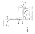
- the locking part 5 is not yet attached to the base part 4. In this position the circumferential edge 8' of the gauze 8 may be positioned between said parts 4 and 5.
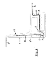
- Figure 3 shows a step of partially entering the locking part 5 into a channel 9 of the base part 4 until the locking members 7 of the locking part have come into locking engagement with upper locking members 6 of the base part 4 while clamping the gauze 8 (more specifically part 8' thereof) between both parts 4 and 5.
- the locking members 6 and 7 are shaped for defining at least a first stable position of the locking part 5 in which it is partially received in the channel 9 of the base part 4.
- An outer part 8" of the gauze still projects from a gap 10 between the base part 4 and locking part 5.
- a cutting knife 12 engages the gauze 8 just above the base part 4 and cuts away the outer part 8" of the gauze 8.
- the locking part 5 may define a cutting counter part for the cutting knife 12.
- figure 4 shows the step of fully entering the locking part 5 into the channel 9 of the base part 4.
- the cutting edge of the gauze 8 is pulled downwards below the upper edge of the base part 4 into the gap 10 and is hidden from view.
- the locking members 7 of the locking part 5 cooperate with the lower locking members 6' of the base part for defining a second stable position of the locking part 5 in which it is fully received in the channel 9 of the base part 4 and in which the gauze 8 is firmly clamped between said parts 4 and 5.
- the mounting wing 3 is illustrated clearly which, in the position of the locking part 5 in which it is fully received in said channel 9 according to figure 4 , covers the gap 10 between the base part 4 and the locking part 5 receiving the outer edge 8' of the gauze 8.
- cooperating locking members 6, 6'and 7 of the base part 4 and locking part 5 define snap locks
- other solutions for defining stable positions of the parts 4 and 5 relative to each other are conceivable, such as for example when the cooperating locking members of the base part and locking part are defined by wall parts frictionally engaging each other (directly or indirectly via the gauze 8).
- the insect screen may be mounted in a window opening. This may be established, for example, by positioning the mounting wing 3 of the frame 1 in a gap between a stationary part and movable part of the window (not illustrated but as known per se).
- stationary part and movable part also may be part of, for example, a door opening or other opening.
Landscapes
- Engineering & Computer Science (AREA)
- Structural Engineering (AREA)
- Life Sciences & Earth Sciences (AREA)
- Insects & Arthropods (AREA)
- Pest Control & Pesticides (AREA)
- Architecture (AREA)
- Civil Engineering (AREA)
- Catching Or Destruction (AREA)
Abstract
Description
- The invention firstly relates to a method for the fabrication of an insect screen of the type for mounting in a window opening and comprising a surrounding frame defining a central opening and a gauze spanning said central opening, wherein the frame comprises a base part provided with a channel which opens toward one side of the frame and wherein a circumferential edge of the gauze is received in said channel and locked therein by a locking part.
- According to a state of the art method of the above type, the locking part comprises an elongate flexible member, e.g. made out of rubber material. When the circumferential edge of the gauze has been received in the channel and has been locked therein by the locking part, the outermost part of the circumferential edge projects from the channel beyond the locking part, thus compromising the aesthetics of the insect screen.
- It is an object of the present invention to provide an improved method of the type referred to above.
- Thus, in accordance with the present invention, the method is characterized in that it comprises a step of partially entering the locking part into the channel of the base part, a step of removing excess edge material of the gauze and a step of fully entering the locking part into the channel, wherein the step of removing excess edge material is carried out before the locking part has fully entered the channel.
- Because the step of removing excess edge material is carried out before the locking part has fully entered the channel (or, in other words, when the locking part has only partially entered said base part), the cutting edge in the gauze will be pushed into the base part when the locking part is fully entered into the channel. As a result the cutting edge then is hidden from view by the base part and the insect screen has improved aesthetics.
- It is noted that the step of partially entering the locking part into the channel of the base part, the step of removing excess edge material of the gauze and the step of fully entering the locking part into the channel may be carried out successively, but it is conceivable too to combine steps, such as the step of removing excess material and the step of fully entering the locking part into the channel (in which case the removal of excess material might be caused by the step of fully entering the locking part, e.g. by a cutting operation caused by cooperating parts of the base part and locking part).
- In a preferred embodiment of the method according to the invention, the step of removing excess edge material of the gauze comprises cutting away the excess material through cutting means. But also other removal processes may be applied (among others depending on the material of the gauze).
- Preferably, during cutting away the excess edge material of the gauze the locking part defines a cutting counter part for the cutting means. Thus the locking part defines a support for the gauze, increasing the efficiency of the cutting process.
- In an embodiment of the method the cutting means comprise a knife. Such a knife may be operated by automated means, or manually.
- According to another embodiment of the method according to the present invention said base part and locking part are provided with cooperating locking members for locking the locking part to the base part while clamping the gauze between both parts, which locking members are shaped for defining at least a first stable position of the locking part in which it is partially received in the channel of the base part, and a second stable position of the locking part in which it is fully received in said channel.
- In the first stable position the excess edge material of the gauze is removed, and in the second stable position the insect screen is fully assembled and the outermost part of the circumferential edge of the gauze is hidden from view.
- Preferably, the cooperating locking members of the base part and locking part define snap locks.
- As an alternative an embodiment of the method is mentioned according to which the cooperating locking members of the base part and locking part are defined by wall parts frictionally engaging each other (in such a case the cooperating locking members may define more then two stable positions, e.g. an infinite amount of stable positions).
- The invention secondly relates to an insect screen of the type for mounting in a window opening and comprising a surrounding frame defining a central opening and a gauze spanning said central opening, wherein the frame comprises a base part provided with a channel which opens toward one side of the frame and wherein a circumferential edge of the gauze is received in said channel and locked therein by a locking part.
- According to the present invention such an insect screen is characterized in that said base part and locking part are provided with cooperating locking members for locking the locking part to the base part while clamping the gauze between both parts, which locking members are shaped for defining at least a first stable position of the locking part in which it is partially received in the channel of the base part, and a second stable position of the locking part in which it is fully received in said channel.
- Such locking members allow the production of the insect screen in accordance with the method according to the present invention.
- In a preferred embodiment of the insect screen according to the present invention the locking part is provided with a projecting wing which, in the position of the locking part in which it is fully received in said channel, covers the gap between the base part and the locking part receiving the outer edge of the gauze.
- Such a projecting wing contributes to an improved aesthetics of the insect screen, but may also be used for mounting the insect screen in the window opening, e.g. between a stationary part and a movable part of the window.
- It is noted that, although the insect screen is described here as applicable to a window opening, it is also conceivable that the insect screen is used in combination with another opening, such as for example a door opening. Further it is noted that the insect screen may be of a type having a stationary gauze or a type having a movable gauze.
- Hereinafter the invention will be elucidated while referring to the drawings, in which
-
Figure 1 shows, in an perspective view, an embodiment of the insect screen according to the invention; -
Figure 2 shows, in a cross section, a base part and locking part in a disassembled state; -
Figure 3 shows, in accordance withfigure 2 , the base part and locking part in an partly assembled state, and -
Figure 4 shows, in accordance withfigure 2 , the base part and locking part in the fully assembled state. - Firstly referring to
figure 1 , an insect screen for mounting in a window opening is illustrated. It comprises a surrounding frame 1 defining acentral opening 2 and a gauze 8 (not illustrated infigure 1 ) spanning saidcentral opening 2. Such agauze 8 is connected to the frame 1 with its circumferential edge. - The frame is provided with an outwardly projecting mounting
wing 3 to be received between a stationary part and a movable part of the window. The mounting wing, in the illustrated embodiment, extends all around the circumference of the frame 1, but it is conceivable too that themounting wing 3 is not present at some locations. - Referring to
figures 2 ,3 and4 , the frame comprises abase part 4 and aseparate locking part 5. Saidbase part 4 and lockingpart 5 are provided with cooperatinglocking members 6, 6'and 7 (in the present embodiment locking fingers defining snap locks) for defining stable positions of thelocking part 5 relative to thebase part 4. - In
figure 2 thelocking part 5 is not yet attached to thebase part 4. In this position the circumferential edge 8' of thegauze 8 may be positioned between saidparts -
Figure 3 shows a step of partially entering thelocking part 5 into achannel 9 of thebase part 4 until thelocking members 7 of the locking part have come into locking engagement withupper locking members 6 of thebase part 4 while clamping the gauze 8 (more specifically part 8' thereof) between bothparts locking members locking part 5 in which it is partially received in thechannel 9 of thebase part 4. Anouter part 8" of the gauze still projects from agap 10 between thebase part 4 and lockingpart 5. - In the position of
figure 3 acutting knife 12 engages thegauze 8 just above thebase part 4 and cuts away theouter part 8" of thegauze 8. During this cutting step thelocking part 5 may define a cutting counter part for thecutting knife 12. - Finally,
figure 4 shows the step of fully entering thelocking part 5 into thechannel 9 of thebase part 4. As a result, the cutting edge of thegauze 8 is pulled downwards below the upper edge of thebase part 4 into thegap 10 and is hidden from view. - In the position illustrated in
figure 4 thelocking members 7 of thelocking part 5 cooperate with the lower locking members 6' of the base part for defining a second stable position of thelocking part 5 in which it is fully received in thechannel 9 of thebase part 4 and in which thegauze 8 is firmly clamped between saidparts - The
mounting wing 3 is illustrated clearly which, in the position of thelocking part 5 in which it is fully received in saidchannel 9 according tofigure 4 , covers thegap 10 between thebase part 4 and thelocking part 5 receiving the outer edge 8' of thegauze 8. - Although in the illustrated embodiment the cooperating
locking members 6, 6'and 7 of thebase part 4 and lockingpart 5 define snap locks, also other solutions for defining stable positions of theparts - Once assembled in accordance with
figure 4 , the insect screen may be mounted in a window opening. This may be established, for example, by positioning themounting wing 3 of the frame 1 in a gap between a stationary part and movable part of the window (not illustrated but as known per se). - Of course, such a stationary part and movable part also may be part of, for example, a door opening or other opening.
- The invention is not limited to the embodiments described above, which may be varied widely within the scope of the invention as defined by the appending claims.
Claims (11)
- Method for the fabrication of an insect screen of the type for mounting in a window opening and comprising a surrounding frame defining a central opening and a gauze spanning said central opening, wherein the frame comprises a base part provided with a channel which opens toward one side of the frame and wherein a circumferential edge of the gauze is received in said channel and locked therein by a locking part, characterized in that the method comprises a step of partially entering the locking part into the channel of the base part, a step of removing excess edge material of the gauze and a step of fully entering the locking part into the channel, wherein the step of removing excess edge material is carried out before the locking part has fully entered the channel.
- Method according to claim 1, wherein the step of removing excess edge material of the gauze comprises cutting away the excess material through cutting means.
- Method according to claim 2, wherein during cutting away the excess edge material of the gauze the locking part defines a cutting counter part for the cutting means.
- Method according to claim 2 or 3, wherein the cutting means comprise a knife.
- Method according to any of the previous claims, wherein said base part and locking part are provided with cooperating locking members for locking the locking part to the base part while clamping the gauze between both parts, which locking members are shaped for defining at least a first stable position of the locking part in which it is partially received in the channel of the base part, and a second stable position of the locking part in which it is fully received in said channel.
- Method according to claim 5, wherein the cooperating locking members of the base part and locking part define snap locks.
- Method according to claim 5, wherein the cooperating locking members of the base part and locking part are defined by wall parts frictionally engaging each other.
- Insect screen of the type for mounting in a window opening and comprising a surrounding frame defining a central opening and a gauze spanning said central opening, wherein the frame comprises a base part provided with a channel which opens toward one side of the frame and wherein a circumferential edge of the gauze is received in said channel and locked therein by a locking part, characterized in that said base part and locking part are provided with cooperating locking members for locking the locking part to the base part while clamping the gauze between both parts, which locking members are shaped for defining at least a first stable position of the locking part in which it is partially received in the channel of the base part, and a second stable position of the locking part in which it is fully received in said channel.
- Insect screen according to claim 8, wherein the cooperating locking members of the base part and locking part define snap locks.
- Insect screen according to claim 9, wherein the cooperating locking members of the base part and locking part are defined by wall parts frictionally engaging each other.
- Insect screen according to any of the claims 8-10, wherein the locking part is provided with a projecting wing which, in the position of the locking part in which it is fully received in said channel, covers the gap between the base part and the locking part receiving the outer edge of the gauze.
Priority Applications (1)
| Application Number | Priority Date | Filing Date | Title |
|---|---|---|---|
| EP08159902.9A EP2143871B1 (en) | 2008-07-08 | 2008-07-08 | Method for the production of an insect screen, and insect screen |
Applications Claiming Priority (1)
| Application Number | Priority Date | Filing Date | Title |
|---|---|---|---|
| EP08159902.9A EP2143871B1 (en) | 2008-07-08 | 2008-07-08 | Method for the production of an insect screen, and insect screen |
Publications (2)
| Publication Number | Publication Date |
|---|---|
| EP2143871A1 true EP2143871A1 (en) | 2010-01-13 |
| EP2143871B1 EP2143871B1 (en) | 2016-11-16 |
Family
ID=39832535
Family Applications (1)
| Application Number | Title | Priority Date | Filing Date |
|---|---|---|---|
| EP08159902.9A Not-in-force EP2143871B1 (en) | 2008-07-08 | 2008-07-08 | Method for the production of an insect screen, and insect screen |
Country Status (1)
| Country | Link |
|---|---|
| EP (1) | EP2143871B1 (en) |
Citations (2)
| Publication number | Priority date | Publication date | Assignee | Title |
|---|---|---|---|---|
| US1758720A (en) * | 1929-01-14 | 1930-05-13 | Sodergren John Edward | Screen |
| US4453585A (en) * | 1981-07-10 | 1984-06-12 | Ruggeberg Sr Bruno | Window thermal insulation device |
Family Cites Families (1)
| Publication number | Priority date | Publication date | Assignee | Title |
|---|---|---|---|---|
| US4441290A (en) * | 1979-02-22 | 1984-04-10 | Hartwig-Hartoglass, Inc. | Glazing fastener for mounting either rigid or flexible storm windows |
-
2008
- 2008-07-08 EP EP08159902.9A patent/EP2143871B1/en not_active Not-in-force
Patent Citations (2)
| Publication number | Priority date | Publication date | Assignee | Title |
|---|---|---|---|---|
| US1758720A (en) * | 1929-01-14 | 1930-05-13 | Sodergren John Edward | Screen |
| US4453585A (en) * | 1981-07-10 | 1984-06-12 | Ruggeberg Sr Bruno | Window thermal insulation device |
Also Published As
| Publication number | Publication date |
|---|---|
| EP2143871B1 (en) | 2016-11-16 |
Similar Documents
| Publication | Publication Date | Title |
|---|---|---|
| US5624319A (en) | Process for production of a two-part cage nut | |
| AU2013257429B2 (en) | A retention system for a pliable sheet | |
| US6263945B1 (en) | Venetian blinds | |
| KR102064059B1 (en) | Pressing Aapparatus for Film sheet | |
| EP2335958B1 (en) | Retaining clip, window assembly with such a retaining clip and method for producing such a window assembly | |
| EP2143871B1 (en) | Method for the production of an insect screen, and insect screen | |
| EP1607255A2 (en) | Sealing, trimming or guiding strips | |
| US20180147072A1 (en) | A cartilage slicing apparatus | |
| KR101153228B1 (en) | Bending device for fixed duct clamp | |
| WO2006060395A3 (en) | Blind trimming apparatus and method of trimming blinds | |
| GB2443319A (en) | Molding and end cap mounting structure | |
| JPH0666066A (en) | Window fixing device | |
| KR101238624B1 (en) | Punching mold device for removing burr of mobile phone | |
| CN105458082B (en) | Forming openings method, stamping die and vehicle trim panel on panel | |
| DE2842738A1 (en) | Loudspeaker for motor vehicle - has mounting simplified by using snap-action leaf-springs to lock into hole in support panel | |
| EP1671827A3 (en) | Vehicle door beam with reinforced tab and method for making the same | |
| US7650917B2 (en) | Arched top door facing and system for forming an arched door facing | |
| WO2006060540A3 (en) | Material cutter with a selectable cutting profile | |
| KR20230001606A (en) | Nonbridge Progressive mold | |
| WO2002045912A3 (en) | Method and apparatus for securing a tang to a formed handle | |
| KR101866339B1 (en) | Blade press die to prevent burr for cutting plastic film and manufacture method therefor | |
| KR100360043B1 (en) | A method of vent cap | |
| EP2018941A3 (en) | Cutting device | |
| JPH06221299A (en) | Multiblade fan and manufacture therefor | |
| KR100461674B1 (en) | Press mold |
Legal Events
| Date | Code | Title | Description |
|---|---|---|---|
| PUAI | Public reference made under article 153(3) epc to a published international application that has entered the european phase |
Free format text: ORIGINAL CODE: 0009012 |
|
| AK | Designated contracting states |
Kind code of ref document: A1 Designated state(s): AT BE BG CH CY CZ DE DK EE ES FI FR GB GR HR HU IE IS IT LI LT LU LV MC MT NL NO PL PT RO SE SI SK TR |
|
| AX | Request for extension of the european patent |
Extension state: AL BA MK RS |
|
| 17P | Request for examination filed |
Effective date: 20100225 |
|
| 17Q | First examination report despatched |
Effective date: 20100331 |
|
| AKX | Designation fees paid |
Designated state(s): AT BE BG CH CY CZ DE DK EE ES FI FR GB GR HR HU IE IS IT LI LT LU LV MC MT NL NO PL PT RO SE SI SK TR |
|
| RAP1 | Party data changed (applicant data changed or rights of an application transferred) |
Owner name: HUNTER DOUGLAS INDUSTRIES B.V. |
|
| GRAP | Despatch of communication of intention to grant a patent |
Free format text: ORIGINAL CODE: EPIDOSNIGR1 |
|
| INTG | Intention to grant announced |
Effective date: 20160811 |
|
| GRAS | Grant fee paid |
Free format text: ORIGINAL CODE: EPIDOSNIGR3 |
|
| GRAA | (expected) grant |
Free format text: ORIGINAL CODE: 0009210 |
|
| AK | Designated contracting states |
Kind code of ref document: B1 Designated state(s): AT BE BG CH CY CZ DE DK EE ES FI FR GB GR HR HU IE IS IT LI LT LU LV MC MT NL NO PL PT RO SE SI SK TR |
|
| REG | Reference to a national code |
Ref country code: GB Ref legal event code: FG4D |
|
| REG | Reference to a national code |
Ref country code: CH Ref legal event code: EP |
|
| REG | Reference to a national code |
Ref country code: IE Ref legal event code: FG4D |
|
| REG | Reference to a national code |
Ref country code: AT Ref legal event code: REF Ref document number: 846138 Country of ref document: AT Kind code of ref document: T Effective date: 20161215 |
|
| REG | Reference to a national code |
Ref country code: DE Ref legal event code: R096 Ref document number: 602008047363 Country of ref document: DE |
|
| REG | Reference to a national code |
Ref country code: NL Ref legal event code: FP |
|
| PG25 | Lapsed in a contracting state [announced via postgrant information from national office to epo] |
Ref country code: LV Free format text: LAPSE BECAUSE OF FAILURE TO SUBMIT A TRANSLATION OF THE DESCRIPTION OR TO PAY THE FEE WITHIN THE PRESCRIBED TIME-LIMIT Effective date: 20161116 |
|
| REG | Reference to a national code |
Ref country code: LT Ref legal event code: MG4D |
|
| REG | Reference to a national code |
Ref country code: AT Ref legal event code: MK05 Ref document number: 846138 Country of ref document: AT Kind code of ref document: T Effective date: 20161116 |
|
| PG25 | Lapsed in a contracting state [announced via postgrant information from national office to epo] |
Ref country code: NO Free format text: LAPSE BECAUSE OF FAILURE TO SUBMIT A TRANSLATION OF THE DESCRIPTION OR TO PAY THE FEE WITHIN THE PRESCRIBED TIME-LIMIT Effective date: 20170216 Ref country code: GR Free format text: LAPSE BECAUSE OF FAILURE TO SUBMIT A TRANSLATION OF THE DESCRIPTION OR TO PAY THE FEE WITHIN THE PRESCRIBED TIME-LIMIT Effective date: 20170217 Ref country code: LT Free format text: LAPSE BECAUSE OF FAILURE TO SUBMIT A TRANSLATION OF THE DESCRIPTION OR TO PAY THE FEE WITHIN THE PRESCRIBED TIME-LIMIT Effective date: 20161116 Ref country code: SE Free format text: LAPSE BECAUSE OF FAILURE TO SUBMIT A TRANSLATION OF THE DESCRIPTION OR TO PAY THE FEE WITHIN THE PRESCRIBED TIME-LIMIT Effective date: 20161116 |
|
| PG25 | Lapsed in a contracting state [announced via postgrant information from national office to epo] |
Ref country code: FI Free format text: LAPSE BECAUSE OF FAILURE TO SUBMIT A TRANSLATION OF THE DESCRIPTION OR TO PAY THE FEE WITHIN THE PRESCRIBED TIME-LIMIT Effective date: 20161116 Ref country code: ES Free format text: LAPSE BECAUSE OF FAILURE TO SUBMIT A TRANSLATION OF THE DESCRIPTION OR TO PAY THE FEE WITHIN THE PRESCRIBED TIME-LIMIT Effective date: 20161116 Ref country code: AT Free format text: LAPSE BECAUSE OF FAILURE TO SUBMIT A TRANSLATION OF THE DESCRIPTION OR TO PAY THE FEE WITHIN THE PRESCRIBED TIME-LIMIT Effective date: 20161116 Ref country code: PT Free format text: LAPSE BECAUSE OF FAILURE TO SUBMIT A TRANSLATION OF THE DESCRIPTION OR TO PAY THE FEE WITHIN THE PRESCRIBED TIME-LIMIT Effective date: 20170316 Ref country code: PL Free format text: LAPSE BECAUSE OF FAILURE TO SUBMIT A TRANSLATION OF THE DESCRIPTION OR TO PAY THE FEE WITHIN THE PRESCRIBED TIME-LIMIT Effective date: 20161116 Ref country code: HR Free format text: LAPSE BECAUSE OF FAILURE TO SUBMIT A TRANSLATION OF THE DESCRIPTION OR TO PAY THE FEE WITHIN THE PRESCRIBED TIME-LIMIT Effective date: 20161116 |
|
| REG | Reference to a national code |
Ref country code: FR Ref legal event code: PLFP Year of fee payment: 10 |
|
| PG25 | Lapsed in a contracting state [announced via postgrant information from national office to epo] |
Ref country code: EE Free format text: LAPSE BECAUSE OF FAILURE TO SUBMIT A TRANSLATION OF THE DESCRIPTION OR TO PAY THE FEE WITHIN THE PRESCRIBED TIME-LIMIT Effective date: 20161116 Ref country code: RO Free format text: LAPSE BECAUSE OF FAILURE TO SUBMIT A TRANSLATION OF THE DESCRIPTION OR TO PAY THE FEE WITHIN THE PRESCRIBED TIME-LIMIT Effective date: 20161116 Ref country code: SK Free format text: LAPSE BECAUSE OF FAILURE TO SUBMIT A TRANSLATION OF THE DESCRIPTION OR TO PAY THE FEE WITHIN THE PRESCRIBED TIME-LIMIT Effective date: 20161116 Ref country code: CZ Free format text: LAPSE BECAUSE OF FAILURE TO SUBMIT A TRANSLATION OF THE DESCRIPTION OR TO PAY THE FEE WITHIN THE PRESCRIBED TIME-LIMIT Effective date: 20161116 Ref country code: DK Free format text: LAPSE BECAUSE OF FAILURE TO SUBMIT A TRANSLATION OF THE DESCRIPTION OR TO PAY THE FEE WITHIN THE PRESCRIBED TIME-LIMIT Effective date: 20161116 |
|
| REG | Reference to a national code |
Ref country code: DE Ref legal event code: R097 Ref document number: 602008047363 Country of ref document: DE |
|
| PG25 | Lapsed in a contracting state [announced via postgrant information from national office to epo] |
Ref country code: BG Free format text: LAPSE BECAUSE OF FAILURE TO SUBMIT A TRANSLATION OF THE DESCRIPTION OR TO PAY THE FEE WITHIN THE PRESCRIBED TIME-LIMIT Effective date: 20170216 Ref country code: BE Free format text: LAPSE BECAUSE OF FAILURE TO SUBMIT A TRANSLATION OF THE DESCRIPTION OR TO PAY THE FEE WITHIN THE PRESCRIBED TIME-LIMIT Effective date: 20161116 Ref country code: IT Free format text: LAPSE BECAUSE OF FAILURE TO SUBMIT A TRANSLATION OF THE DESCRIPTION OR TO PAY THE FEE WITHIN THE PRESCRIBED TIME-LIMIT Effective date: 20161116 |
|
| PLBE | No opposition filed within time limit |
Free format text: ORIGINAL CODE: 0009261 |
|
| STAA | Information on the status of an ep patent application or granted ep patent |
Free format text: STATUS: NO OPPOSITION FILED WITHIN TIME LIMIT |
|
| 26N | No opposition filed |
Effective date: 20170817 |
|
| PG25 | Lapsed in a contracting state [announced via postgrant information from national office to epo] |
Ref country code: SI Free format text: LAPSE BECAUSE OF FAILURE TO SUBMIT A TRANSLATION OF THE DESCRIPTION OR TO PAY THE FEE WITHIN THE PRESCRIBED TIME-LIMIT Effective date: 20161116 |
|
| REG | Reference to a national code |
Ref country code: CH Ref legal event code: PL |
|
| GBPC | Gb: european patent ceased through non-payment of renewal fee |
Effective date: 20170708 |
|
| REG | Reference to a national code |
Ref country code: IE Ref legal event code: MM4A |
|
| PG25 | Lapsed in a contracting state [announced via postgrant information from national office to epo] |
Ref country code: IE Free format text: LAPSE BECAUSE OF NON-PAYMENT OF DUE FEES Effective date: 20170708 Ref country code: LI Free format text: LAPSE BECAUSE OF NON-PAYMENT OF DUE FEES Effective date: 20170731 Ref country code: GB Free format text: LAPSE BECAUSE OF NON-PAYMENT OF DUE FEES Effective date: 20170708 Ref country code: CH Free format text: LAPSE BECAUSE OF NON-PAYMENT OF DUE FEES Effective date: 20170731 |
|
| REG | Reference to a national code |
Ref country code: FR Ref legal event code: PLFP Year of fee payment: 11 |
|
| PG25 | Lapsed in a contracting state [announced via postgrant information from national office to epo] |
Ref country code: LU Free format text: LAPSE BECAUSE OF NON-PAYMENT OF DUE FEES Effective date: 20170708 |
|
| PG25 | Lapsed in a contracting state [announced via postgrant information from national office to epo] |
Ref country code: MT Free format text: LAPSE BECAUSE OF NON-PAYMENT OF DUE FEES Effective date: 20170708 |
|
| PG25 | Lapsed in a contracting state [announced via postgrant information from national office to epo] |
Ref country code: HU Free format text: LAPSE BECAUSE OF FAILURE TO SUBMIT A TRANSLATION OF THE DESCRIPTION OR TO PAY THE FEE WITHIN THE PRESCRIBED TIME-LIMIT; INVALID AB INITIO Effective date: 20080708 Ref country code: MC Free format text: LAPSE BECAUSE OF FAILURE TO SUBMIT A TRANSLATION OF THE DESCRIPTION OR TO PAY THE FEE WITHIN THE PRESCRIBED TIME-LIMIT Effective date: 20161116 |
|
| PG25 | Lapsed in a contracting state [announced via postgrant information from national office to epo] |
Ref country code: CY Free format text: LAPSE BECAUSE OF NON-PAYMENT OF DUE FEES Effective date: 20161116 |
|
| PG25 | Lapsed in a contracting state [announced via postgrant information from national office to epo] |
Ref country code: TR Free format text: LAPSE BECAUSE OF FAILURE TO SUBMIT A TRANSLATION OF THE DESCRIPTION OR TO PAY THE FEE WITHIN THE PRESCRIBED TIME-LIMIT Effective date: 20161116 |
|
| PG25 | Lapsed in a contracting state [announced via postgrant information from national office to epo] |
Ref country code: IS Free format text: LAPSE BECAUSE OF FAILURE TO SUBMIT A TRANSLATION OF THE DESCRIPTION OR TO PAY THE FEE WITHIN THE PRESCRIBED TIME-LIMIT Effective date: 20170316 |
|
| P01 | Opt-out of the competence of the unified patent court (upc) registered |
Effective date: 20230517 |
|
| PGFP | Annual fee paid to national office [announced via postgrant information from national office to epo] |
Ref country code: NL Payment date: 20240527 Year of fee payment: 17 |
|
| PGFP | Annual fee paid to national office [announced via postgrant information from national office to epo] |
Ref country code: FR Payment date: 20240524 Year of fee payment: 17 |
|
| PGFP | Annual fee paid to national office [announced via postgrant information from national office to epo] |
Ref country code: DE Payment date: 20240522 Year of fee payment: 17 |
|
| REG | Reference to a national code |
Ref country code: DE Ref legal event code: R119 Ref document number: 602008047363 Country of ref document: DE |
|
| REG | Reference to a national code |
Ref country code: NL Ref legal event code: MM Effective date: 20250801 |
|
| PG25 | Lapsed in a contracting state [announced via postgrant information from national office to epo] |
Ref country code: DE Free format text: LAPSE BECAUSE OF NON-PAYMENT OF DUE FEES Effective date: 20260203 |
|
| PG25 | Lapsed in a contracting state [announced via postgrant information from national office to epo] |
Ref country code: NL Free format text: LAPSE BECAUSE OF NON-PAYMENT OF DUE FEES Effective date: 20250801 |
|
| PG25 | Lapsed in a contracting state [announced via postgrant information from national office to epo] |
Ref country code: FR Free format text: LAPSE BECAUSE OF NON-PAYMENT OF DUE FEES Effective date: 20250731 |