EP2143539A1 - Elevated plate arrangement - Google Patents
Elevated plate arrangement Download PDFInfo
- Publication number
- EP2143539A1 EP2143539A1 EP08388025A EP08388025A EP2143539A1 EP 2143539 A1 EP2143539 A1 EP 2143539A1 EP 08388025 A EP08388025 A EP 08388025A EP 08388025 A EP08388025 A EP 08388025A EP 2143539 A1 EP2143539 A1 EP 2143539A1
- Authority
- EP
- European Patent Office
- Prior art keywords
- preinsulated
- mould
- pipe
- insulation material
- pipes
- Prior art date
- Legal status (The legal status is an assumption and is not a legal conclusion. Google has not performed a legal analysis and makes no representation as to the accuracy of the status listed.)
- Granted
Links
Images


Classifications
-
- B—PERFORMING OPERATIONS; TRANSPORTING
- B29—WORKING OF PLASTICS; WORKING OF SUBSTANCES IN A PLASTIC STATE IN GENERAL
- B29C—SHAPING OR JOINING OF PLASTICS; SHAPING OF MATERIAL IN A PLASTIC STATE, NOT OTHERWISE PROVIDED FOR; AFTER-TREATMENT OF THE SHAPED PRODUCTS, e.g. REPAIRING
- B29C44/00—Shaping by internal pressure generated in the material, e.g. swelling or foaming ; Producing porous or cellular expanded plastics articles
- B29C44/20—Shaping by internal pressure generated in the material, e.g. swelling or foaming ; Producing porous or cellular expanded plastics articles for articles of indefinite length
- B29C44/32—Incorporating or moulding on preformed parts, e.g. linings, inserts or reinforcements
- B29C44/322—Incorporating or moulding on preformed parts, e.g. linings, inserts or reinforcements the preformed parts being elongated inserts, e.g. cables
- B29C44/324—Incorporating or moulding on preformed parts, e.g. linings, inserts or reinforcements the preformed parts being elongated inserts, e.g. cables the preformed parts being tubular or folded to a tubular shape
-
- F—MECHANICAL ENGINEERING; LIGHTING; HEATING; WEAPONS; BLASTING
- F16—ENGINEERING ELEMENTS AND UNITS; GENERAL MEASURES FOR PRODUCING AND MAINTAINING EFFECTIVE FUNCTIONING OF MACHINES OR INSTALLATIONS; THERMAL INSULATION IN GENERAL
- F16L—PIPES; JOINTS OR FITTINGS FOR PIPES; SUPPORTS FOR PIPES, CABLES OR PROTECTIVE TUBING; MEANS FOR THERMAL INSULATION IN GENERAL
- F16L59/00—Thermal insulation in general
- F16L59/14—Arrangements for the insulation of pipes or pipe systems
- F16L59/143—Pre-insulated pipes
-
- B—PERFORMING OPERATIONS; TRANSPORTING
- B29—WORKING OF PLASTICS; WORKING OF SUBSTANCES IN A PLASTIC STATE IN GENERAL
- B29L—INDEXING SCHEME ASSOCIATED WITH SUBCLASS B29C, RELATING TO PARTICULAR ARTICLES
- B29L2023/00—Tubular articles
- B29L2023/22—Tubes or pipes, i.e. rigid
- B29L2023/225—Insulated
Definitions
- the present invention relates to an improved manufacture method of preinsulated pipes by means of a continuous process.
- the step of adding the insulation material in a liquid state between the mould and the inner pipe comprises positioning the liquid insulation material in the vicinity of the inner pipe, whereby the material surrounds the inner pipe at an early development stage. This can, among others, be obtained by the use of an elevated plate arrangement.
- preinsulated pipes are widely used.
- An assembly of a preinsulated pipe typically comprises one or more inner pipes of either metal or plastic, an insulation layer such as polyurethane foam and a casing pipe of metal or plastic.
- Preinsulated pipes that are continuously manufactured can further comprise a diffusion barrier in the form of e.g. a film or foil arranged between the insulation layer and the casing material.
- the position of the inner pipes (also referred to as service pipes) relative to for example the casing or centre lines is very important when installing the preinsulated pipes, as the free end of the inner pipes must be welded together or joined otherwise.
- Preinsulated pipes with very diverging positions of the inner pipes can therefore lead to undesired stresses and tension in the assembled preinsulated pipes and increased installation costs.
- the position of the inner pipes relative to the preinsulated pipes as a whole is agreed by the parties or follows the specifications in international and national standards. Such standards normally vary depending on e.g. the application field.
- Twisting concerns the position of the inner pipes in one end of the preinsulated pipe relative to the position in the other end of the same preinsulated pipe. Twisting can also concern the position of the inner pipes in one end of the preinsulated pipes relative to any position along the preinsulated pipe. This requirement is particular relevant when the preinsulated pipes are cut during installation.
- a widespread way of manufacturing preinsulated pipes using a continuous process proceeds as follows:
- the liquid polyurethane foam mixture is poured on an endless sheet, such as plastic film or foil, arranged on the bottom of O-shaped moulds.
- the sheet is moved forward by the moulds with a certain velocity.
- the polyurethane foam mixture expands and gradually fills the gap between the inner pipes fed continuously into the moulds at a velocity corresponding to the velocity of the sheet.
- After full expansion of the liquid polyurethane foam mixture it cures inside the moulds.
- the insulated inner pipes exit the moulds and enter a station where a plastic casing can be extruded onto the insulation material.
- the preinsulated pipes are cut and divided into desired lengths.
- the objective of the present invention is to solve the above mentioned problems.
- a method of manufacturing a preinsulated pipe comprising at least one inner pipe surrounded by insulation material
- the method of manufacturing the preinsulated pipe comprising the steps of adding the insulation material in a liquid state between a mould and the inner pipe and letting the insulation material expand and solidify through a number of consecutive development stages characterized in that the step of adding the insulation material in a liquid state between the mould and the inner pipe comprises positioning the liquid insulation material in the vicinity of the inner pipe, whereby the material surrounds the inner pipe at an early development stage.
- the insulation material is added in a liquid state on a sheet positioned in the vicinity of the inner pipe. This is advantageous as the insulation material can be led more easily into the mould together with the inner pipe.
- the sheet is endless. This is an advantage as this simplifies the manufacturing process, compared to feeding single sheets into the mould.
- the sheet is placed on a slope.
- the advantage of this embodiment is that the sheet is supported whereby the sheet does not have to carry the load of the insulation material alone. Thus, this is conducive for the desired distribution of insulation material.
- the slope is placed in the entering end of the mould. This is advantageous as it is here the insulation material is introduced into the mould.
- the slope comprises side walls.
- the advantage of this is that the walls can assist in obtaining a desired development of the insulation material.
- the slope comprises a horizontal portion perpendicular to the slopping direction of the sloped surface.
- the method comprises an additional sheet directed into the mould at the bottom of the mould. This is advantageous as it is easier to feed a sheet close to the inner pipe that has a smaller width than the circumference of the inside of the mould.
- the slope has its highest point at the entering end of the mould.
- Figure 1 illustrates a sectional view of a prior art preinsulated pipe 100 manufactured according to a continuous process with a single inner pipe 106, where the inner pipe 106 exceeds a given tolerance range indicated by the dotted circle 101.
- the preinsulated pipe comprises the mentioned inner pipe 106 (also called service pipe), insulation material 104 such as polyurethane foam (PUR), alarm wire 108, primary sheet 110 and a casing 102, such as an extruded plastic casing. Due to inaccuracies in the production of the preinsulated pipe 100 according to a continuous process, the inner pipe 106 exceeds the tolerances for the position of the inner pipe 106 relative to the casing 102.
- the problem with this is, as initially stated, that the preinsulated pipes 100 are difficult to install due to the gap size between adjacent inner pipes 106 to be joined. Welding these together can in addition cause undesired stress or tension in the preinsulated pipes 100.
- the width of the primary sheet 110 must at least correspond to the inner circumference of the mould (see figures 6-9 ). If the width of the primary sheet 110 is greater than this circumference, the primary sheet 110 will have an overlap against the inner wall of the casing 102. The function of the primary sheet 110 is described in figure 3 .
- the alarm wire 108 can be used to detect leakage in an installed pipe system. The alarm wire is optional.
- Figure 2 illustrates a sectional view of a prior art preinsulated pipe 200 manufactured according to a continuous process with two inner pipes 206, 207 where the twisting tolerance for the upper inner pipe 206 is indicated.
- the preinsulated pipe 200 comprises two inner pipes 206, 207, insulation material 104 such as polyurethane foam (PUR), alarm wire 108, primary sheet 110 and a casing 102, such as a an extruded plastic casing.
- the twisting tolerance w denotes the allowed horizontal displacement as indicated on the figure. It must be noted that the tolerance w is only a horizontal tolerance when the preinsulated pipe is orientated as indicated on the figure.
- Complying with the twisting tolerances w can be a requirement only at only each end of the preinsulated pipe 200, but where the preinsulated pipes 200 are cut during installation, this can be a requirement along the entire length thereof. A further requirement is the distance between the two inner pipes 206, 207.
- FIG. 3 illustrates a prior art principal sketch of a production line for manufacturing preinsulated pipes 100 according to a continuous process, where the preinsulated pipes comprise one inner pipe.
- the production line could, however, with minor adjustments also be used to manufacture preinsulated pipes with two or more inner pipes.
- the production line comprises an inner pipe feeder (not shown), a sheet dispenser (not shown), a moulding station 322, an extruder 324, a cooling unit 326, 328, a cutting unit 330 and pipe transportations means 332.
- the inner pipes 106 are arranged and put together by a distance piece (not shown) and then fed into the moulding station 322.
- the inner pipe 106 is led into an open circular mould (not shown) of the moulding station 322 together with a primary sheet 110.
- the primary sheet 110 can e.g. be a plastic sheet, which can comprise several layers conducive for the desired properties of the final preinsulated pipe 100.
- the primary sheet 110 is typically an endless sheet and must have a width corresponding to at least the inner circumference of the mould of the moulding station 322 and is led into the mould at the bottom of this.
- an insulation material dispenser 320 injects liquid insulation material (not shown) such as polyurethane foam (PUR) on the primary sheet 110 moving into the mould.
- PUR polyurethane foam
- the liquid insulation material is typically directed at one side of the inner pipe 106 (also illustrated at e.g. figure 6 ), that is between the inner pipe 106 and the mould (not shown) along the primary sheet.
- the liquid insulation material can be dispensed between these, such that it lands on bottom of the mould whereon the primary sheet 110 moves.
- the inner pipe 106 and the primary sheet 110 are moved into the mould of the moulding station 322 at the same velocity.
- the liquid insulation material dispensed into the mould lands on the bottom of the primary sheet, and as it moves into the mould it becomes expanding foam, which gradually supports and surrounds the inner pipe 106 and eventually fills out the entire mould.
- the distribution of the foam or mixture on the bottom part of the mould is not completely even, which means that the foam front(s) do not reach the inner pipe 106 exactly at the same time, which in combination with the relatively high viscosity of the foam at that point of time can cause displacement of the inner pipe 106 from its intended position.
- a preinsulated pipe 200 with two inner pipes 206, 207 this can lead e.g.
- the insulation material 104 has gone through a number of consecutive development stages.
- the insulation material 104 can be a mixture of different substances.
- the development stages in the foaming process of the insulation material has a number of characteristic stages, with the start of the mixing set at zero, referred to as cream stage, then a string or gel stage, then a tack-free stage and finally an end-of-rise stage.
- the cream stage is when the mix starts to foam.
- the string or gel stage is when strings of polymer can be withdrawn by dipping a pointer into the foam mix.
- the tack-free stage is when the surface of the foam stops being tacky to touch.
- the end-of-rise stage is when the point of maximum height is reached.
- the insulation material 104 cures inside the mould of the moulding station which comprises heating means such that the temperature of the mould is set at a temperature conducive to the curing process.
- the insulated inner pipe leaves the moulding station 322.
- the casing 102 of the preinsulated pipe 100 is extruded on the insulated inner pipe 106 at the extruder 324.
- the preinsulated pipe 100 is cooled at the cooling unit 326, 328, and subsequently cut in a desired length at cutting unit 330.
- the preinsulated pipes are normally cut where the distance piece between two successive inner pipes 106 is installed.
- the finished preinsulated pipes 100 leave the production line at a station comprising pipe transportations means 332.
- FIG 4 illustrates a perspective of an elevated plate arrangement 400.
- the elevated plate arrangement 400 resembles a slide elevating from approximately zero height in one end to a greater height at the other.
- the elevated plate arrangement 400 is placed in the mould of a moulding station and arranged such that the high end of the elevated plate is placed in or at the entering end of the mould. This means that the elevated plate has a downward slope into the mould.
- the top of the mould is placed close to the point where the inner pipe enters the mould. The reasoning of this is explained in the following figures.
- Figure 5 illustrates a side view of the elevated plate arrangement 400 and four cross sections along the course of the same.
- the descending height of the elevated plate arrangement can be seen in the cross sections 550 (F-F), 552 (A-A), 554 (B-B), 556 (E-E).
- These cross sectional views also illustrate how the (side) walls of the elevated plate arrangement 400 decrease along with the descending height of the same.
- the elevated plate 400 can be shaped differently according to e.g. the characteristics of the insulation material which is to be directed onto the slope of the elevated plate arrangement 400.
- Figure 6 illustrates a cross sectional view 600 of the production of a preinsulated pipe with a single inner pipe 106, where two sheets 110, 660 are used.
- the production of the preinsulated pipe 100 resembles the manufacturing process described in figure 3 and further comprises an elevated plate arrangement 400 with a different design compared to the one described in figures 4 and 5 . That is, here the elevated plate arrangement 400 is adapted to the geometry of the single inner pipe 106. Therefore, apart from the elevated plate arrangement 400 and the secondary sheet 660, the production of the preinsulated pipe 100 resembles the one described in figure 3 .
- the secondary sheet 660 is directed into the mould 662 at the top of the elevated plate arrangement 400 and the primary sheet 110 beneath the elevated plate arrangement 400 along the mould 662.
- the wall of the mould 662 facing the inner pipe 106 is shown.
- the liquid insulation material 104 When the liquid insulation material 104 is directed into the mould 662, it lands on the secondary sheet 660 and expands from there. Since the inner pipe 106 and the elevated plate arrangement 400 are relatively close to each other at the entering end of the mould 662, the expanding insulation material is almost immediately brought into contact with the inner pipe 106, i.e. at a point of time where the viscosity of the foam 104 is still very low, and hence the impact on the displacement of the inner pipe 106 is also very low.
- the elevated plate arrangement 400 has a slope and ends before the foam 104 is fully expanded and closes the gap between the inner pipe 106 and the walls of the mould 662 between which the primary sheet 110 is positioned.
- the elevated plate arrangement 400 may have several inclination points and may be adjustable in height and length to accommodate variations in foam reactivity.
- Figure 7 illustrates a cross sectional view of the production of a preinsulated pipe 200 according to a continuous process with two inner pipes 206, 207, where two sheets 110, 660 are used.
- the production of the preinsulated pipe 200 further comprises an elevated plate arrangement 400. Apart from the elevated plate arrangement 400 and the secondary sheet 660, the production of the preinsulated pipe 100 resembles the one described in figure 3 .
- the secondary sheet 660 is directed into the mould 662 at the top of the elevated plate arrangement 400 and the primary sheet 110 beneath the elevated plate arrangement 400. When the liquid insulation material 104 is directed into the mould 662 it lands on the secondary sheet 660 and expands from there.
- the elevated plate arrangement 400 further has a horizontal part which provides an even distribution of the liquid insulation material 104 and subsequently an even expansion thereof.
- the elevated plate arrangement 400 has a slope and ends before the insulation material 104 is fully expanded and closes the gap between the inner pipes 206, 207 and the walls of the mould 662.
- the elevated plate arrangement 400 may have several inclination points and may be adjustable in height and length to accommodate variations in the foam 104 reactivity.
- Figure 8 illustrates a cross sectional view of the production of a preinsulated pipe 200 according to a continuous process with two inner pipes 206, 207, where only one secondary sheet 660 is used.
- the width of the secondary sheet 660 is larger than the secondary sheet in figure 7 .
- the larger width ensures that the insulation material 104 does not adhere to the wall of the mould 662.
- the secondary sheet 660 must in this setting have a width which is at least equal to the circumference of the inside of the mould 662.
- the production of the preinsulated pipe 200 further comprises an elevated plate arrangement 400. Apart from the elevated plate arrangement 400 and the secondary sheet 660, the production of the preinsulated pipe 100 resembles the one described in figure 3 - although, in this particular setting, the primary sheet 110 is omitted.
- the secondary sheet 660 is directed into the mould 662 at the top of the elevated plate arrangement 400, which is arranged at the entering end of the mould 662.
- the liquid insulation material 104 When the liquid insulation material 104 is directed into the mould 662, it lands on the secondary sheet 660 and expands from there. Since the inner pipes 206, 207 and the elevated plate arrangement 400 are relatively close to each other at the entering end of the mould 662, the expanding insulation material 104 is almost immediately brought into contact with the inner pipes 206, 207, i.e. at a point of time where the viscosity of the foam 104 is still very low, and hence the impact on the displacement of the inner pipes 206, 207 is also very low.
- the elevated plate arrangement 400 further has a horizontal part which provides an even distribution of the liquid insulation material 104 and an even expansion thereof.
- the slope of the elevated plate arrangement 400 ends (not shown) inside the mould 662 before the insulation material 104 is fully expanded and closes the gap between the inner pipes 206, 207 and the walls of the mould 662.
- the elevated plate arrangement 400 may have several inclination points and may be adjustable in height and length to accommodate variations in the foam 104 reactivity.
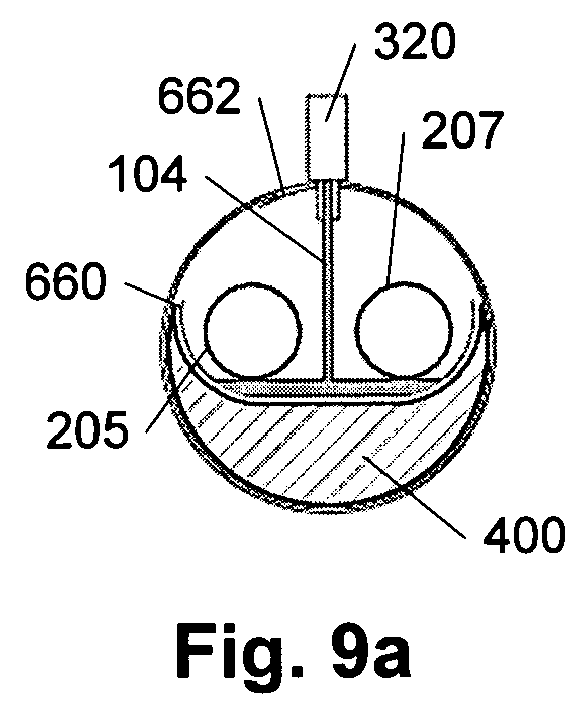
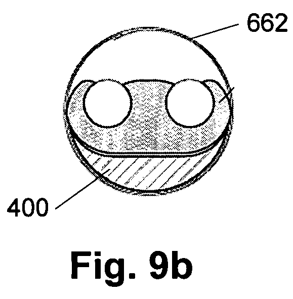
- Figure 9a-d illustrate four cross sectional views during the manufacture of a preinsulated pipe with two inner pipes 206, 207 along the course of the elevated plate arrangement 400.
- the liquid foam 104 is directed into the mould 662 between the two inner pipes 206, 207.
- the foam 104 gradually expands ( figure 9b ) and surrounds ( figure 9b ) the inner pipes 206, 207, and eventually the foam 104 fills out the majority of the mould 662 ( figure 9d ).
- this elevated plate arrangement 400 provides an even distribution of foam liquid 104, a fast contact with the inner pipes 206, 207, and hence less impact on the displacement and, due to the vertical expansion in both upward and downward direction, a better density and material property distribution of the foam 104.
- alarm wires 108 may be fed in continuously parallel to the inner pipes 206, 207 at any point above the elevated plate arrangement 400.
- a common advantage of the embodiments described in figures 6-9 is the faster enclosure of the inner pipe. This is especially advantageous in the continuous manufacture of preinsulated pipes with at least two inner pipes, as the insulation material expands from the centre of the preinsulated pipes and out against the walls of the mould.
- the inner pipes which can be considered as an obstacle to the expansion of insulation material, are surrounded at a very early stage in the development of the insulation material compared to the prior art. This because the insulation material foam expands from the center of the preinsulated pipe and not from the bottom of the mould as it is the case with the prior art. Further, as the insulation material passes the inner pipes at this stage the foam is distributed much more homogeneously compared to prior art.
Landscapes
- Engineering & Computer Science (AREA)
- General Engineering & Computer Science (AREA)
- Mechanical Engineering (AREA)
- Thermal Insulation (AREA)
- Casting Or Compression Moulding Of Plastics Or The Like (AREA)
Abstract

Description
- The present invention relates to an improved manufacture method of preinsulated pipes by means of a continuous process. The step of adding the insulation material in a liquid state between the mould and the inner pipe comprises positioning the liquid insulation material in the vicinity of the inner pipe, whereby the material surrounds the inner pipe at an early development stage. This can, among others, be obtained by the use of an elevated plate arrangement.
- For district heating and cooling solutions in e.g. the oil and gas sector and for industry insulation, preinsulated pipes are widely used. An assembly of a preinsulated pipe typically comprises one or more inner pipes of either metal or plastic, an insulation layer such as polyurethane foam and a casing pipe of metal or plastic. Preinsulated pipes that are continuously manufactured can further comprise a diffusion barrier in the form of e.g. a film or foil arranged between the insulation layer and the casing material.
- The position of the inner pipes (also referred to as service pipes) relative to for example the casing or centre lines is very important when installing the preinsulated pipes, as the free end of the inner pipes must be welded together or joined otherwise. Preinsulated pipes with very diverging positions of the inner pipes can therefore lead to undesired stresses and tension in the assembled preinsulated pipes and increased installation costs. To avoid this, the position of the inner pipes relative to the preinsulated pipes as a whole, is agreed by the parties or follows the specifications in international and national standards. Such standards normally vary depending on e.g. the application field.
- When two or more inner pipes are used, a further requirement must be fulfilled. This relates to the twisting of the inner pipes, which must be held within a certain tolerance range. Twisting concerns the position of the inner pipes in one end of the preinsulated pipe relative to the position in the other end of the same preinsulated pipe. Twisting can also concern the position of the inner pipes in one end of the preinsulated pipes relative to any position along the preinsulated pipe. This requirement is particular relevant when the preinsulated pipes are cut during installation.
- A widespread way of manufacturing preinsulated pipes using a continuous process proceeds as follows: The liquid polyurethane foam mixture is poured on an endless sheet, such as plastic film or foil, arranged on the bottom of O-shaped moulds. The sheet is moved forward by the moulds with a certain velocity. The polyurethane foam mixture expands and gradually fills the gap between the inner pipes fed continuously into the moulds at a velocity corresponding to the velocity of the sheet. After full expansion of the liquid polyurethane foam mixture, it cures inside the moulds. Subsequently, the insulated inner pipes exit the moulds and enter a station where a plastic casing can be extruded onto the insulation material. Finally, the preinsulated pipes are cut and divided into desired lengths.
- During the expansion of the polyurethane foam mixture, the viscosity steadily increases from approximately 200-400mPa·s at 25 °C to higher viscosity and finally to a solid state, where the foam cures. The distribution of the polyurethane foam mixture on the endless sheet arranged on the bottom of the mould is rarely completely even; hence the front(s) of the foam do not reach the inner pipes exactly at the same time. Since the viscosity of the foam is relatively high at that point of time, this can cause displacement of the inner pipes from their intended position. This may lead to an undesired position of single inner pipes relative to e.g. the casing. In the case of preinsulated pipes with two or more inner pipes, this might lead to the undesired twisting described above.
- The objective of the present invention is to solve the above mentioned problems.
- This is obtained by providing a method of manufacturing a preinsulated pipe, the preinsulated pipe comprising at least one inner pipe surrounded by insulation material and the method of manufacturing the preinsulated pipe comprising the steps of adding the insulation material in a liquid state between a mould and the inner pipe and letting the insulation material expand and solidify through a number of consecutive development stages characterized in that the step of adding the insulation material in a liquid state between the mould and the inner pipe comprises positioning the liquid insulation material in the vicinity of the inner pipe, whereby the material surrounds the inner pipe at an early development stage. The advantage of this is that the inner pipe is enclosed by the insulation material much earlier compared to the prior art. This is especially advantageous in the continuous manufacture of preinsulated pipes with at least two inner pipes, as the insulation material expands from the centre of the preinsulated pipes and out against the walls of the mould. Thus, the inner pipes, which can be considered as an obstacle to the expansion of insulation material, are enclosed at a very early stage in the development of the insulation material from liquid to solidification. Further, as the insulation material passes the inner pipes at this stage, the foam is distributed much more homogeneously. This is advantageous as the homogeneous distribution leads to an even solidification of the insulation material, which has a minimum impact on the displacement of the inner pipe.
- In another embodiment of the present invention, the insulation material is added in a liquid state on a sheet positioned in the vicinity of the inner pipe. This is advantageous as the insulation material can be led more easily into the mould together with the inner pipe.
- In a further embodiment of the present invention, the sheet is endless. This is an advantage as this simplifies the manufacturing process, compared to feeding single sheets into the mould.
- In yet another embodiment of the present invention the development of stages of the insulation material moves the sheet towards the walls of the mould. Here the advantages are as described above.
- In another embodiment of the present invention, the sheet is placed on a slope. The advantage of this embodiment is that the sheet is supported whereby the sheet does not have to carry the load of the insulation material alone. Thus, this is conducive for the desired distribution of insulation material.
- In a further embodiment of the present invention, the slope is placed in the entering end of the mould. This is advantageous as it is here the insulation material is introduced into the mould.
- In yet another embodiment of the present invention, the slope comprises side walls. The advantage of this is that the walls can assist in obtaining a desired development of the insulation material.
- In another embodiment of the present invention, the slope comprises a horizontal portion perpendicular to the slopping direction of the sloped surface. Here the advantages are as described above.
- In a further embodiment of the present invention, the method comprises an additional sheet directed into the mould at the bottom of the mould. This is advantageous as it is easier to feed a sheet close to the inner pipe that has a smaller width than the circumference of the inside of the mould.
- In yet another embodiment of the present invention, the slope has its highest point at the entering end of the mould. Here the advantages are as described above.
- In the following, preferred embodiments of the invention will be described referring to the figures, where
-
figure 1 illustrates a sectional view of a prior art preinsulated pipe with a single inner pipe, where the inner pipe exceeds a given tolerance range; -
figure 2 illustrates a sectional view of a prior art preinsulated pipe with two service pipes where the twisting tolerance for the upper inner pipe is indicated; -
figure 3 illustrates a prior art principal sketch of a production line for manufacturing preinsulated pipes according to a continuous process comprising one or more inner pipes; -
figure 4 illustrates a perspective of the elevated plate arrangement; -
figure 5 illustrates a side view of the elevated plate arrangement and four cross sections along the course of the same; -
figure 6 illustrates a cross sectional view of the production of a preinsulated pipe with a single inner pipe, where two sheets are used; -
figure 7 illustrates a cross sectional view of the production of a preinsulated pipe with two inner pipes, where two sheets are used; -
figure 8 illustrates a cross sectional view of the production of a preinsulated pipe with two inner pipes, where one sheet is used; -
figure 9a-d illustrate four cross sectional views during the manufacture of a preinsulated pipe with two inner pipes along the course of the elevated plate arrangement. -
Figure 1 illustrates a sectional view of a priorart preinsulated pipe 100 manufactured according to a continuous process with a singleinner pipe 106, where theinner pipe 106 exceeds a given tolerance range indicated by the dottedcircle 101. The preinsulated pipe comprises the mentioned inner pipe 106 (also called service pipe),insulation material 104 such as polyurethane foam (PUR),alarm wire 108,primary sheet 110 and acasing 102, such as an extruded plastic casing. Due to inaccuracies in the production of thepreinsulated pipe 100 according to a continuous process, theinner pipe 106 exceeds the tolerances for the position of theinner pipe 106 relative to thecasing 102. The problem with this is, as initially stated, that thepreinsulated pipes 100 are difficult to install due to the gap size between adjacentinner pipes 106 to be joined. Welding these together can in addition cause undesired stress or tension in thepreinsulated pipes 100. The width of theprimary sheet 110 must at least correspond to the inner circumference of the mould (seefigures 6-9 ). If the width of theprimary sheet 110 is greater than this circumference, theprimary sheet 110 will have an overlap against the inner wall of thecasing 102. The function of theprimary sheet 110 is described infigure 3 . Thealarm wire 108 can be used to detect leakage in an installed pipe system. The alarm wire is optional. -
Figure 2 illustrates a sectional view of a priorart preinsulated pipe 200 manufactured according to a continuous process with twoinner pipes inner pipe 206 is indicated. Thepreinsulated pipe 200 comprises twoinner pipes insulation material 104 such as polyurethane foam (PUR),alarm wire 108,primary sheet 110 and acasing 102, such as a an extruded plastic casing. The twisting tolerance w denotes the allowed horizontal displacement as indicated on the figure. It must be noted that the tolerance w is only a horizontal tolerance when the preinsulated pipe is orientated as indicated on the figure. Complying with the twisting tolerances w can be a requirement only at only each end of thepreinsulated pipe 200, but where thepreinsulated pipes 200 are cut during installation, this can be a requirement along the entire length thereof. A further requirement is the distance between the twoinner pipes -
Figure 3 illustrates a prior art principal sketch of a production line for manufacturingpreinsulated pipes 100 according to a continuous process, where the preinsulated pipes comprise one inner pipe. The production line could, however, with minor adjustments also be used to manufacture preinsulated pipes with two or more inner pipes. The production line comprises an inner pipe feeder (not shown), a sheet dispenser (not shown), amoulding station 322, anextruder 324, acooling unit cutting unit 330 and pipe transportations means 332. At the inner pipe feeder, theinner pipes 106 are arranged and put together by a distance piece (not shown) and then fed into themoulding station 322. Theinner pipe 106 is led into an open circular mould (not shown) of themoulding station 322 together with aprimary sheet 110. Theprimary sheet 110 can e.g. be a plastic sheet, which can comprise several layers conducive for the desired properties of the finalpreinsulated pipe 100. Theprimary sheet 110 is typically an endless sheet and must have a width corresponding to at least the inner circumference of the mould of themoulding station 322 and is led into the mould at the bottom of this. In this entering end of themoulding station 322, aninsulation material dispenser 320 injects liquid insulation material (not shown) such as polyurethane foam (PUR) on theprimary sheet 110 moving into the mould. Theprimary sheet 110 is used so as to avoid that the insulation material gets stuck to the wall of the mould, which could cause undesired problems with the continuity of the production of thesepreinsulated pipes 100. In the case of manufacturingpreinsulated pipes 100 with a singleinner pipe 106, the liquid insulation material is typically directed at one side of the inner pipe 106 (also illustrated at e.g.figure 6 ), that is between theinner pipe 106 and the mould (not shown) along the primary sheet. In the case of apreinsulated pipe 200 with twoinner pipes primary sheet 110 moves. Theinner pipe 106 and theprimary sheet 110 are moved into the mould of themoulding station 322 at the same velocity. The liquid insulation material dispensed into the mould lands on the bottom of the primary sheet, and as it moves into the mould it becomes expanding foam, which gradually supports and surrounds theinner pipe 106 and eventually fills out the entire mould. In most cases the distribution of the foam or mixture on the bottom part of the mould is not completely even, which means that the foam front(s) do not reach theinner pipe 106 exactly at the same time, which in combination with the relatively high viscosity of the foam at that point of time can cause displacement of theinner pipe 106 from its intended position. This leads to a displacement relative to thecasing 102 of apreinsulated pipe 100 with a singleinner pipe 106, seefigure 1 . In the case of apreinsulated pipe 200 with twoinner pipes inner pipes figure 2 . When the insulatedinner pipe 106 leaves themoulding station 322, theinsulation material 104 has gone through a number of consecutive development stages. Theinsulation material 104 can be a mixture of different substances. The development stages in the foaming process of the insulation material has a number of characteristic stages, with the start of the mixing set at zero, referred to as cream stage, then a string or gel stage, then a tack-free stage and finally an end-of-rise stage. The cream stage is when the mix starts to foam. The string or gel stage is when strings of polymer can be withdrawn by dipping a pointer into the foam mix. The tack-free stage is when the surface of the foam stops being tacky to touch. Finally, the end-of-rise stage is when the point of maximum height is reached. Hereafter theinsulation material 104 cures inside the mould of the moulding station which comprises heating means such that the temperature of the mould is set at a temperature conducive to the curing process. Then the insulated inner pipe leaves themoulding station 322. Hereafter thecasing 102 of thepreinsulated pipe 100 is extruded on the insulatedinner pipe 106 at theextruder 324. Then thepreinsulated pipe 100 is cooled at thecooling unit unit 330. The preinsulated pipes are normally cut where the distance piece between two successiveinner pipes 106 is installed. Finally, the finishedpreinsulated pipes 100 leave the production line at a station comprising pipe transportations means 332. -
Figure 4 illustrates a perspective of anelevated plate arrangement 400. Theelevated plate arrangement 400 resembles a slide elevating from approximately zero height in one end to a greater height at the other. Theelevated plate arrangement 400 is placed in the mould of a moulding station and arranged such that the high end of the elevated plate is placed in or at the entering end of the mould. This means that the elevated plate has a downward slope into the mould. The top of the mould is placed close to the point where the inner pipe enters the mould. The reasoning of this is explained in the following figures. -
Figure 5 illustrates a side view of theelevated plate arrangement 400 and four cross sections along the course of the same. The descending height of the elevated plate arrangement can be seen in the cross sections 550 (F-F), 552 (A-A), 554 (B-B), 556 (E-E). These cross sectional views also illustrate how the (side) walls of theelevated plate arrangement 400 decrease along with the descending height of the same. Theelevated plate 400 can be shaped differently according to e.g. the characteristics of the insulation material which is to be directed onto the slope of theelevated plate arrangement 400. -
Figure 6 illustrates a crosssectional view 600 of the production of a preinsulated pipe with a singleinner pipe 106, where twosheets preinsulated pipe 100 resembles the manufacturing process described infigure 3 and further comprises anelevated plate arrangement 400 with a different design compared to the one described infigures 4 and5 . That is, here theelevated plate arrangement 400 is adapted to the geometry of the singleinner pipe 106. Therefore, apart from theelevated plate arrangement 400 and thesecondary sheet 660, the production of thepreinsulated pipe 100 resembles the one described infigure 3 . Thesecondary sheet 660 is directed into themould 662 at the top of theelevated plate arrangement 400 and theprimary sheet 110 beneath theelevated plate arrangement 400 along themould 662. For illustrative purposes only, the wall of themould 662 facing theinner pipe 106 is shown. When theliquid insulation material 104 is directed into themould 662, it lands on thesecondary sheet 660 and expands from there. Since theinner pipe 106 and theelevated plate arrangement 400 are relatively close to each other at the entering end of themould 662, the expanding insulation material is almost immediately brought into contact with theinner pipe 106, i.e. at a point of time where the viscosity of thefoam 104 is still very low, and hence the impact on the displacement of theinner pipe 106 is also very low. Theelevated plate arrangement 400 has a slope and ends before thefoam 104 is fully expanded and closes the gap between theinner pipe 106 and the walls of themould 662 between which theprimary sheet 110 is positioned. Theelevated plate arrangement 400 may have several inclination points and may be adjustable in height and length to accommodate variations in foam reactivity. -
Figure 7 illustrates a cross sectional view of the production of apreinsulated pipe 200 according to a continuous process with twoinner pipes sheets preinsulated pipe 200 further comprises anelevated plate arrangement 400. Apart from theelevated plate arrangement 400 and thesecondary sheet 660, the production of thepreinsulated pipe 100 resembles the one described infigure 3 . Thesecondary sheet 660 is directed into themould 662 at the top of theelevated plate arrangement 400 and theprimary sheet 110 beneath theelevated plate arrangement 400. When theliquid insulation material 104 is directed into themould 662 it lands on thesecondary sheet 660 and expands from there. Since theinner pipes elevated plate arrangement 400 are relatively close to each other at the entering end of themould 662, the expanding foam is almost immediately brought into contact with theinner pipes foam 104 is still very low, and hence the impact on the displacement of theinner pipes elevated plate arrangement 400 further has a horizontal part which provides an even distribution of theliquid insulation material 104 and subsequently an even expansion thereof. Theelevated plate arrangement 400 has a slope and ends before theinsulation material 104 is fully expanded and closes the gap between theinner pipes mould 662. Theelevated plate arrangement 400 may have several inclination points and may be adjustable in height and length to accommodate variations in thefoam 104 reactivity. -
Figure 8 illustrates a cross sectional view of the production of apreinsulated pipe 200 according to a continuous process with twoinner pipes secondary sheet 660 is used. Here the width of thesecondary sheet 660 is larger than the secondary sheet infigure 7 . The larger width ensures that theinsulation material 104 does not adhere to the wall of themould 662. Thus, thesecondary sheet 660 must in this setting have a width which is at least equal to the circumference of the inside of themould 662. The production of thepreinsulated pipe 200 further comprises anelevated plate arrangement 400. Apart from theelevated plate arrangement 400 and thesecondary sheet 660, the production of thepreinsulated pipe 100 resembles the one described infigure 3 - although, in this particular setting, theprimary sheet 110 is omitted. Thesecondary sheet 660 is directed into themould 662 at the top of theelevated plate arrangement 400, which is arranged at the entering end of themould 662. When theliquid insulation material 104 is directed into themould 662, it lands on thesecondary sheet 660 and expands from there. Since theinner pipes elevated plate arrangement 400 are relatively close to each other at the entering end of themould 662, the expandinginsulation material 104 is almost immediately brought into contact with theinner pipes foam 104 is still very low, and hence the impact on the displacement of theinner pipes elevated plate arrangement 400 further has a horizontal part which provides an even distribution of theliquid insulation material 104 and an even expansion thereof. The slope of theelevated plate arrangement 400 ends (not shown) inside themould 662 before theinsulation material 104 is fully expanded and closes the gap between theinner pipes mould 662. Theelevated plate arrangement 400 may have several inclination points and may be adjustable in height and length to accommodate variations in thefoam 104 reactivity. -
Figure 9a-d illustrate four cross sectional views during the manufacture of a preinsulated pipe with twoinner pipes elevated plate arrangement 400. Infigure 9a theliquid foam 104 is directed into themould 662 between the twoinner pipes secondary sheet 660 and theinner pipes mould 662 along the descendingelevated plate arrangement 400, thefoam 104 gradually expands (figure 9b ) and surrounds (figure 9b ) theinner pipes foam 104 fills out the majority of the mould 662 (figure 9d ). As illustrated, thiselevated plate arrangement 400 provides an even distribution offoam liquid 104, a fast contact with theinner pipes foam 104. As it is common practice,alarm wires 108 may be fed in continuously parallel to theinner pipes elevated plate arrangement 400. - A common advantage of the embodiments described in
figures 6-9 is the faster enclosure of the inner pipe. This is especially advantageous in the continuous manufacture of preinsulated pipes with at least two inner pipes, as the insulation material expands from the centre of the preinsulated pipes and out against the walls of the mould. Thus, the inner pipes, which can be considered as an obstacle to the expansion of insulation material, are surrounded at a very early stage in the development of the insulation material compared to the prior art. This because the insulation material foam expands from the center of the preinsulated pipe and not from the bottom of the mould as it is the case with the prior art. Further, as the insulation material passes the inner pipes at this stage the foam is distributed much more homogeneously compared to prior art. This leads to another advantage of the present invention, as the homogeneous distribution leads to an even solidification of the insulation material having a minimum impact on the displacement of the inner pipes. Manufacture of preinsulated pipes according to the present invention using an elevated plate arrangement is schematically illustrated in the table below:Time (example) Foam development Physical event Continuous process 0 seconds Raw material mixing Liquid lay down on carrier sheet 5 seconds Cream, initial rise Froth formation >5 - < 60 seconds Rising foam Viscosity increase, bubble expansion Foam surrounds the inner pipe(s) Foam has completely filled the gap between the inner pipe(s) and the mould walls 40 seconds Foam gels Temperature and pressure inside the cells increase 50 seconds Foam becomes tack free 60 seconds End-of-rise Foam becomes solid > 60 seconds Cure Hardness development 180 seconds Pipe assembly leaves the mould sections > 180 seconds Extrusion of casing and cutting -
- 100
- preinsulated pipe with a single inner pipe
- 101
- dotted circle for max. tolerance
- 102
- casing
- 104
- insulation material (liquid as well as solidified state)
- 106
- inner pipe
- 108
- alarm wire
- 110
- primary sheet
- 200
- preinsulated pipe with two inner pipes
- 206
- inner pipe
- 207
- inner pipe
- 300
- production line for the manufacture of preinsulated pipes
- 320
- foam dispenser
- 322
- moulding station
- 324
- extruder
- 326
- cooling station
- 328
- cooling station
- 330
- cutting station
- 332
- pipe transportation means
- 400
- elevated plate arrangement, sloped surface
- 550
- cross section of the elevated plate arrangement
- 552
- cross section of the elevated plate arrangement
- 554
- cross section of the elevated plate arrangement
- 556
- cross section of the elevated plate arrangement
- 600
- cross sectional of the production of a preinsulated pipe with a single inner pipe using two sheets
- 660
- secondary sheet
- 662
- mould wall of the moulding station
- 700
- cross sectional of the production of a preinsulated pipe with a two inner pipes using two sheets
- 800
- cross sectional of the production of a preinsulated pipe with a two inner pipes using two sheets
Claims (10)
- A method of manufacturing a preinsulated pipe, said preinsulated pipe comprising at least one inner pipe surrounded by insulation material, said method of manufacturing said preinsulated pipe comprising the steps of adding said insulation material in a liquid state between a mould and said inner pipe and letting said insulation material expand and solidify through a number of consecutive development stages characterized in that said step of adding said insulation material in a liquid state between said mould and said inner pipe comprises positioning said liquid insulation material in the vicinity of said inner pipe, whereby said material surrounds said inner pipe at an early development stage.
- A method of manufacturing a preinsulated pipe according to claim 1, wherein said insulation material is added in a liquid state on a sheet positioned in the vicinity of said inner pipe.
- A method of manufacturing a preinsulated pipe according to claims 1-2, wherein said sheet is endless.
- A method of manufacturing a preinsulated pipe according to claims 1-3, wherein the development of stages of said insulation material moves said sheet towards the walls of said mould.
- A method of manufacturing a preinsulated pipe according to claims 1-4, wherein said sheet is placed on a slope.
- A method of manufacturing a preinsulated pipe according to claims 1-5, wherein said slope is placed in the entering end of the said mould.
- A method of manufacturing a preinsulated pipe according to claims 1-6, wherein said slope comprises side walls.
- A method of manufacturing a preinsulated pipe according to claims 1-7, where said slope comprises a horizontal portion perpendicular to the slopping direction of the sloped surface.
- A method of manufacturing a preinsulated pipe according to claims 1-8, wherein said method comprises an additional sheet directed into said mould at the bottom of said mould.
- A method of manufacturing a preinsulated pipe according to claims 1-9, wherein said slope has its highest point at the entering end of said mould.
Priority Applications (3)
| Application Number | Priority Date | Filing Date | Title |
|---|---|---|---|
| PL08388025T PL2143539T3 (en) | 2008-07-10 | 2008-07-10 | Method of manufacturing a preinsulated pipe and production line |
| DK08388025.2T DK2143539T3 (en) | 2008-07-10 | 2008-07-10 | A process for producing a pre-insulated pipes and production |
| EP08388025.2A EP2143539B1 (en) | 2008-07-10 | 2008-07-10 | Method of manufacturing a preinsulated pipe and production line |
Applications Claiming Priority (1)
| Application Number | Priority Date | Filing Date | Title |
|---|---|---|---|
| EP08388025.2A EP2143539B1 (en) | 2008-07-10 | 2008-07-10 | Method of manufacturing a preinsulated pipe and production line |
Publications (2)
| Publication Number | Publication Date |
|---|---|
| EP2143539A1 true EP2143539A1 (en) | 2010-01-13 |
| EP2143539B1 EP2143539B1 (en) | 2015-11-11 |
Family
ID=40227515
Family Applications (1)
| Application Number | Title | Priority Date | Filing Date |
|---|---|---|---|
| EP08388025.2A Active EP2143539B1 (en) | 2008-07-10 | 2008-07-10 | Method of manufacturing a preinsulated pipe and production line |
Country Status (3)
| Country | Link |
|---|---|
| EP (1) | EP2143539B1 (en) |
| DK (1) | DK2143539T3 (en) |
| PL (1) | PL2143539T3 (en) |
Cited By (5)
| Publication number | Priority date | Publication date | Assignee | Title |
|---|---|---|---|---|
| WO2014012877A1 (en) | 2012-07-17 | 2014-01-23 | Basf Se | Method for continuous production of foams in tubes |
| WO2018219916A1 (en) | 2017-05-30 | 2018-12-06 | Basf Se | Method for producing insulated pipes |
| WO2020201312A1 (en) | 2019-04-02 | 2020-10-08 | Basf Se | Insulated pipe containing polyurethane foam which is foamed by an environmentally friendly foaming agent and has a low degree of brittleness |
| CN113067963A (en) * | 2019-12-31 | 2021-07-02 | 杭州海康威视数字技术股份有限公司 | Camera and refrigerating device thereof |
| EP4008737A1 (en) | 2020-12-02 | 2022-06-08 | Logstor A/S | An insulated pipe with an increased compressive strength and axial shear strength |
Citations (4)
| Publication number | Priority date | Publication date | Assignee | Title |
|---|---|---|---|---|
| US3325573A (en) * | 1964-04-07 | 1967-06-13 | Reeves Bros Inc | Manufacture of foam material |
| GB1246940A (en) * | 1968-01-05 | 1971-09-22 | Tenneco Chem | Improvements in or relating to forming foamed cellular product from a liquid reaction mixture |
| GB1277865A (en) | 1969-12-04 | 1972-06-14 | Kabel Metallwerke Ghh | Method and apparatus for producing pipes |
| US20060032588A1 (en) | 2004-08-13 | 2006-02-16 | Robert Appleby | Method and system for cast molding a fluid conduit |
-
2008
- 2008-07-10 PL PL08388025T patent/PL2143539T3/en unknown
- 2008-07-10 EP EP08388025.2A patent/EP2143539B1/en active Active
- 2008-07-10 DK DK08388025.2T patent/DK2143539T3/en active
Patent Citations (4)
| Publication number | Priority date | Publication date | Assignee | Title |
|---|---|---|---|---|
| US3325573A (en) * | 1964-04-07 | 1967-06-13 | Reeves Bros Inc | Manufacture of foam material |
| GB1246940A (en) * | 1968-01-05 | 1971-09-22 | Tenneco Chem | Improvements in or relating to forming foamed cellular product from a liquid reaction mixture |
| GB1277865A (en) | 1969-12-04 | 1972-06-14 | Kabel Metallwerke Ghh | Method and apparatus for producing pipes |
| US20060032588A1 (en) | 2004-08-13 | 2006-02-16 | Robert Appleby | Method and system for cast molding a fluid conduit |
Cited By (8)
| Publication number | Priority date | Publication date | Assignee | Title |
|---|---|---|---|---|
| WO2014012877A1 (en) | 2012-07-17 | 2014-01-23 | Basf Se | Method for continuous production of foams in tubes |
| WO2018219916A1 (en) | 2017-05-30 | 2018-12-06 | Basf Se | Method for producing insulated pipes |
| US11472152B2 (en) | 2017-05-30 | 2022-10-18 | Basf Se | Method for producing insulated pipes |
| WO2020201312A1 (en) | 2019-04-02 | 2020-10-08 | Basf Se | Insulated pipe containing polyurethane foam which is foamed by an environmentally friendly foaming agent and has a low degree of brittleness |
| US11982395B2 (en) | 2019-04-02 | 2024-05-14 | Basf Se | Insulated pipe containing polyurethane foam which is foamed by an environmentally friendly foaming agent and has a low degree of brittleness |
| CN113067963A (en) * | 2019-12-31 | 2021-07-02 | 杭州海康威视数字技术股份有限公司 | Camera and refrigerating device thereof |
| CN113067963B (en) * | 2019-12-31 | 2022-07-19 | 杭州海康威视数字技术股份有限公司 | Camera and refrigerating device thereof |
| EP4008737A1 (en) | 2020-12-02 | 2022-06-08 | Logstor A/S | An insulated pipe with an increased compressive strength and axial shear strength |
Also Published As
| Publication number | Publication date |
|---|---|
| PL2143539T3 (en) | 2016-04-29 |
| DK2143539T3 (en) | 2016-01-25 |
| EP2143539B1 (en) | 2015-11-11 |
Similar Documents
| Publication | Publication Date | Title |
|---|---|---|
| EP2143539B1 (en) | Method of manufacturing a preinsulated pipe and production line | |
| CN100367418C (en) | Coaxial cable and method of manufacturing the same | |
| AU724140B2 (en) | Coaxial cable | |
| US5122044A (en) | Apparatus for making a drip irrigation conduit | |
| EP2620268B1 (en) | Line for manufacturing a heat-insulated flexible pipe | |
| CN102822263B (en) | Sheet composition for a pipe connection, and sheet for electrofoaming fusion and connecting apparatus for underground pipes using the sheet composition | |
| US3530029A (en) | Composite sheet forming apparatus and method | |
| KR20210006898A (en) | Method and apparatus for manufacturing thermally insulated pipe | |
| EA013854B1 (en) | Method and apparatus for manufacturing an elongated product and product | |
| CN113146991B (en) | Anti-displacement and easy-to-install embedded steel-edge rubber waterstop and equipment tooling and preparation process | |
| US20020069532A1 (en) | Insulated formwork panels and process for their manufacture | |
| US20060032588A1 (en) | Method and system for cast molding a fluid conduit | |
| CA2602354C (en) | Method and apparatus for a sensor wire | |
| DK2964996T3 (en) | Heat insulated corrugated conduit | |
| EP2586602B1 (en) | Method for manufacturing a thermally insulated flexible tube | |
| JP2015002100A (en) | Coaxial cable | |
| KR100928668B1 (en) | Double insulation tube, manufacturing apparatus and manufacturing method | |
| US8343396B2 (en) | Insulating foam sections | |
| KR102517139B1 (en) | Single-collar water supply and sewer pipes and their molding devices to compensate for the decrease in thickness due to expansion | |
| JPS6218340B2 (en) | ||
| WO2002065485A3 (en) | Facility and method for manufacturing coaxial wire with foamed insulation | |
| EP1734198B1 (en) | Method for producing a thermoinsulating panel and panel so obtained | |
| KR980008374A (en) | Method of manufacturing insulated conduits | |
| US3409961A (en) | Apparatus for making composite sheet materials | |
| CN105817747A (en) | Argon arc welding machine for shaped circular seams of reinforced steel-plastic composite pipes |
Legal Events
| Date | Code | Title | Description |
|---|---|---|---|
| PUAI | Public reference made under article 153(3) epc to a published international application that has entered the european phase |
Free format text: ORIGINAL CODE: 0009012 |
|
| AK | Designated contracting states |
Kind code of ref document: A1 Designated state(s): AT BE BG CH CY CZ DE DK EE ES FI FR GB GR HR HU IE IS IT LI LT LU LV MC MT NL NO PL PT RO SE SI SK TR |
|
| AX | Request for extension of the european patent |
Extension state: AL BA MK RS |
|
| 17P | Request for examination filed |
Effective date: 20100629 |
|
| AKX | Designation fees paid |
Designated state(s): AT BE BG CH CY CZ DE DK EE ES FI FR GB GR HR HU IE IS IT LI LT LU LV MC MT NL NO PL PT RO SE SI SK TR |
|
| 17Q | First examination report despatched |
Effective date: 20130402 |
|
| GRAP | Despatch of communication of intention to grant a patent |
Free format text: ORIGINAL CODE: EPIDOSNIGR1 |
|
| RIC1 | Information provided on ipc code assigned before grant |
Ipc: F16L 59/14 20060101AFI20150521BHEP Ipc: B29L 23/00 20060101ALN20150521BHEP Ipc: B29C 44/32 20060101ALI20150521BHEP |
|
| RIC1 | Information provided on ipc code assigned before grant |
Ipc: F16L 59/14 20060101AFI20150527BHEP Ipc: B29C 44/32 20060101ALI20150527BHEP Ipc: B29L 23/00 20060101ALN20150527BHEP |
|
| INTG | Intention to grant announced |
Effective date: 20150610 |
|
| REG | Reference to a national code |
Ref country code: DE Ref legal event code: R079 Ref document number: 602008041098 Country of ref document: DE Free format text: PREVIOUS MAIN CLASS: B29C0044320000 Ipc: F16L0059140000 |
|
| GRAS | Grant fee paid |
Free format text: ORIGINAL CODE: EPIDOSNIGR3 |
|
| GRAP | Despatch of communication of intention to grant a patent |
Free format text: ORIGINAL CODE: EPIDOSNIGR1 |
|
| GRAA | (expected) grant |
Free format text: ORIGINAL CODE: 0009210 |
|
| RIC1 | Information provided on ipc code assigned before grant |
Ipc: F16L 59/14 20060101AFI20150914BHEP Ipc: B29C 44/32 20060101ALI20150914BHEP Ipc: B29L 23/00 20060101ALN20150914BHEP |
|
| INTG | Intention to grant announced |
Effective date: 20150930 |
|
| AK | Designated contracting states |
Kind code of ref document: B1 Designated state(s): AT BE BG CH CY CZ DE DK EE ES FI FR GB GR HR HU IE IS IT LI LT LU LV MC MT NL NO PL PT RO SE SI SK TR |
|
| REG | Reference to a national code |
Ref country code: GB Ref legal event code: FG4D |
|
| RIN1 | Information on inventor provided before grant (corrected) |
Inventor name: THOMSEN, TINA Inventor name: BROENNUM, THOMAS Inventor name: PEDERSEN, MARTIN |
|
| REG | Reference to a national code |
Ref country code: CH Ref legal event code: EP |
|
| REG | Reference to a national code |
Ref country code: IE Ref legal event code: FG4D |
|
| REG | Reference to a national code |
Ref country code: AT Ref legal event code: REF Ref document number: 760646 Country of ref document: AT Kind code of ref document: T Effective date: 20151215 |
|
| REG | Reference to a national code |
Ref country code: DE Ref legal event code: R096 Ref document number: 602008041098 Country of ref document: DE |
|
| REG | Reference to a national code |
Ref country code: DK Ref legal event code: T3 Effective date: 20160118 |
|
| REG | Reference to a national code |
Ref country code: RO Ref legal event code: EPE |
|
| REG | Reference to a national code |
Ref country code: LT Ref legal event code: MG4D |
|
| REG | Reference to a national code |
Ref country code: NL Ref legal event code: MP Effective date: 20160211 |
|
| PG25 | Lapsed in a contracting state [announced via postgrant information from national office to epo] |
Ref country code: HR Free format text: LAPSE BECAUSE OF FAILURE TO SUBMIT A TRANSLATION OF THE DESCRIPTION OR TO PAY THE FEE WITHIN THE PRESCRIBED TIME-LIMIT Effective date: 20151111 Ref country code: ES Free format text: LAPSE BECAUSE OF FAILURE TO SUBMIT A TRANSLATION OF THE DESCRIPTION OR TO PAY THE FEE WITHIN THE PRESCRIBED TIME-LIMIT Effective date: 20151111 Ref country code: NO Free format text: LAPSE BECAUSE OF FAILURE TO SUBMIT A TRANSLATION OF THE DESCRIPTION OR TO PAY THE FEE WITHIN THE PRESCRIBED TIME-LIMIT Effective date: 20160211 Ref country code: IS Free format text: LAPSE BECAUSE OF FAILURE TO SUBMIT A TRANSLATION OF THE DESCRIPTION OR TO PAY THE FEE WITHIN THE PRESCRIBED TIME-LIMIT Effective date: 20160311 Ref country code: LT Free format text: LAPSE BECAUSE OF FAILURE TO SUBMIT A TRANSLATION OF THE DESCRIPTION OR TO PAY THE FEE WITHIN THE PRESCRIBED TIME-LIMIT Effective date: 20151111 Ref country code: IT Free format text: LAPSE BECAUSE OF FAILURE TO SUBMIT A TRANSLATION OF THE DESCRIPTION OR TO PAY THE FEE WITHIN THE PRESCRIBED TIME-LIMIT Effective date: 20151111 Ref country code: NL Free format text: LAPSE BECAUSE OF FAILURE TO SUBMIT A TRANSLATION OF THE DESCRIPTION OR TO PAY THE FEE WITHIN THE PRESCRIBED TIME-LIMIT Effective date: 20151111 |
|
| PG25 | Lapsed in a contracting state [announced via postgrant information from national office to epo] |
Ref country code: LV Free format text: LAPSE BECAUSE OF FAILURE TO SUBMIT A TRANSLATION OF THE DESCRIPTION OR TO PAY THE FEE WITHIN THE PRESCRIBED TIME-LIMIT Effective date: 20151111 Ref country code: SE Free format text: LAPSE BECAUSE OF FAILURE TO SUBMIT A TRANSLATION OF THE DESCRIPTION OR TO PAY THE FEE WITHIN THE PRESCRIBED TIME-LIMIT Effective date: 20151111 Ref country code: GR Free format text: LAPSE BECAUSE OF FAILURE TO SUBMIT A TRANSLATION OF THE DESCRIPTION OR TO PAY THE FEE WITHIN THE PRESCRIBED TIME-LIMIT Effective date: 20160212 Ref country code: FI Free format text: LAPSE BECAUSE OF FAILURE TO SUBMIT A TRANSLATION OF THE DESCRIPTION OR TO PAY THE FEE WITHIN THE PRESCRIBED TIME-LIMIT Effective date: 20151111 Ref country code: PT Free format text: LAPSE BECAUSE OF FAILURE TO SUBMIT A TRANSLATION OF THE DESCRIPTION OR TO PAY THE FEE WITHIN THE PRESCRIBED TIME-LIMIT Effective date: 20160311 |
|
| REG | Reference to a national code |
Ref country code: SK Ref legal event code: T3 Ref document number: E 20418 Country of ref document: SK |
|
| PG25 | Lapsed in a contracting state [announced via postgrant information from national office to epo] |
Ref country code: CZ Free format text: LAPSE BECAUSE OF FAILURE TO SUBMIT A TRANSLATION OF THE DESCRIPTION OR TO PAY THE FEE WITHIN THE PRESCRIBED TIME-LIMIT Effective date: 20151111 |
|
| REG | Reference to a national code |
Ref country code: DE Ref legal event code: R097 Ref document number: 602008041098 Country of ref document: DE |
|
| PG25 | Lapsed in a contracting state [announced via postgrant information from national office to epo] |
Ref country code: EE Free format text: LAPSE BECAUSE OF FAILURE TO SUBMIT A TRANSLATION OF THE DESCRIPTION OR TO PAY THE FEE WITHIN THE PRESCRIBED TIME-LIMIT Effective date: 20151111 |
|
| PLBE | No opposition filed within time limit |
Free format text: ORIGINAL CODE: 0009261 |
|
| STAA | Information on the status of an ep patent application or granted ep patent |
Free format text: STATUS: NO OPPOSITION FILED WITHIN TIME LIMIT |
|
| 26N | No opposition filed |
Effective date: 20160812 |
|
| PG25 | Lapsed in a contracting state [announced via postgrant information from national office to epo] |
Ref country code: SI Free format text: LAPSE BECAUSE OF FAILURE TO SUBMIT A TRANSLATION OF THE DESCRIPTION OR TO PAY THE FEE WITHIN THE PRESCRIBED TIME-LIMIT Effective date: 20151111 |
|
| PG25 | Lapsed in a contracting state [announced via postgrant information from national office to epo] |
Ref country code: BE Free format text: LAPSE BECAUSE OF FAILURE TO SUBMIT A TRANSLATION OF THE DESCRIPTION OR TO PAY THE FEE WITHIN THE PRESCRIBED TIME-LIMIT Effective date: 20151111 |
|
| REG | Reference to a national code |
Ref country code: CH Ref legal event code: PL |
|
| GBPC | Gb: european patent ceased through non-payment of renewal fee |
Effective date: 20160710 |
|
| PG25 | Lapsed in a contracting state [announced via postgrant information from national office to epo] |
Ref country code: MC Free format text: LAPSE BECAUSE OF FAILURE TO SUBMIT A TRANSLATION OF THE DESCRIPTION OR TO PAY THE FEE WITHIN THE PRESCRIBED TIME-LIMIT Effective date: 20151111 |
|
| PG25 | Lapsed in a contracting state [announced via postgrant information from national office to epo] |
Ref country code: FR Free format text: LAPSE BECAUSE OF NON-PAYMENT OF DUE FEES Effective date: 20160801 Ref country code: CH Free format text: LAPSE BECAUSE OF NON-PAYMENT OF DUE FEES Effective date: 20160731 Ref country code: LI Free format text: LAPSE BECAUSE OF NON-PAYMENT OF DUE FEES Effective date: 20160731 |
|
| REG | Reference to a national code |
Ref country code: FR Ref legal event code: ST Effective date: 20170331 |
|
| REG | Reference to a national code |
Ref country code: IE Ref legal event code: MM4A |
|
| PG25 | Lapsed in a contracting state [announced via postgrant information from national office to epo] |
Ref country code: GB Free format text: LAPSE BECAUSE OF NON-PAYMENT OF DUE FEES Effective date: 20160710 |
|
| PG25 | Lapsed in a contracting state [announced via postgrant information from national office to epo] |
Ref country code: IE Free format text: LAPSE BECAUSE OF NON-PAYMENT OF DUE FEES Effective date: 20160710 |
|
| PG25 | Lapsed in a contracting state [announced via postgrant information from national office to epo] |
Ref country code: LU Free format text: LAPSE BECAUSE OF NON-PAYMENT OF DUE FEES Effective date: 20160710 |
|
| REG | Reference to a national code |
Ref country code: AT Ref legal event code: UEP Ref document number: 760646 Country of ref document: AT Kind code of ref document: T Effective date: 20151111 |
|
| PG25 | Lapsed in a contracting state [announced via postgrant information from national office to epo] |
Ref country code: HU Free format text: LAPSE BECAUSE OF FAILURE TO SUBMIT A TRANSLATION OF THE DESCRIPTION OR TO PAY THE FEE WITHIN THE PRESCRIBED TIME-LIMIT; INVALID AB INITIO Effective date: 20080710 Ref country code: CY Free format text: LAPSE BECAUSE OF FAILURE TO SUBMIT A TRANSLATION OF THE DESCRIPTION OR TO PAY THE FEE WITHIN THE PRESCRIBED TIME-LIMIT Effective date: 20151111 |
|
| PG25 | Lapsed in a contracting state [announced via postgrant information from national office to epo] |
Ref country code: MT Free format text: LAPSE BECAUSE OF NON-PAYMENT OF DUE FEES Effective date: 20160731 Ref country code: TR Free format text: LAPSE BECAUSE OF FAILURE TO SUBMIT A TRANSLATION OF THE DESCRIPTION OR TO PAY THE FEE WITHIN THE PRESCRIBED TIME-LIMIT Effective date: 20151111 |
|
| PG25 | Lapsed in a contracting state [announced via postgrant information from national office to epo] |
Ref country code: BG Free format text: LAPSE BECAUSE OF FAILURE TO SUBMIT A TRANSLATION OF THE DESCRIPTION OR TO PAY THE FEE WITHIN THE PRESCRIBED TIME-LIMIT Effective date: 20151111 |
|
| P01 | Opt-out of the competence of the unified patent court (upc) registered |
Effective date: 20230530 |
|
| PGFP | Annual fee paid to national office [announced via postgrant information from national office to epo] |
Ref country code: SK Payment date: 20250624 Year of fee payment: 18 |
|
| PGFP | Annual fee paid to national office [announced via postgrant information from national office to epo] |
Ref country code: DE Payment date: 20250610 Year of fee payment: 18 Ref country code: DK Payment date: 20250704 Year of fee payment: 18 |
|
| PGFP | Annual fee paid to national office [announced via postgrant information from national office to epo] |
Ref country code: PL Payment date: 20250704 Year of fee payment: 18 |
|
| PGFP | Annual fee paid to national office [announced via postgrant information from national office to epo] |
Ref country code: AT Payment date: 20250718 Year of fee payment: 18 |
|
| PGFP | Annual fee paid to national office [announced via postgrant information from national office to epo] |
Ref country code: RO Payment date: 20250702 Year of fee payment: 18 |