EP2142859B1 - Enclosure for a solar collector - Google Patents
Enclosure for a solar collector Download PDFInfo
- Publication number
- EP2142859B1 EP2142859B1 EP08738341.0A EP08738341A EP2142859B1 EP 2142859 B1 EP2142859 B1 EP 2142859B1 EP 08738341 A EP08738341 A EP 08738341A EP 2142859 B1 EP2142859 B1 EP 2142859B1
- Authority
- EP
- European Patent Office
- Prior art keywords
- enclosure
- solar collector
- panel unit
- air vent
- collector according
- Prior art date
- Legal status (The legal status is an assumption and is not a legal conclusion. Google has not performed a legal analysis and makes no representation as to the accuracy of the status listed.)
- Not-in-force
Links
- 230000007246 mechanism Effects 0.000 claims description 22
- 239000004033 plastic Substances 0.000 claims description 13
- 229920003023 plastic Polymers 0.000 claims description 13
- 239000000463 material Substances 0.000 claims description 9
- 230000008602 contraction Effects 0.000 claims description 6
- XLYOFNOQVPJJNP-UHFFFAOYSA-N water Substances O XLYOFNOQVPJJNP-UHFFFAOYSA-N 0.000 description 4
- 239000008236 heating water Substances 0.000 description 2
- 238000009423 ventilation Methods 0.000 description 2
- 230000006866 deterioration Effects 0.000 description 1
- 230000001627 detrimental effect Effects 0.000 description 1
- 230000000694 effects Effects 0.000 description 1
- 239000011521 glass Substances 0.000 description 1
- 229920002635 polyurethane Polymers 0.000 description 1
- 239000004814 polyurethane Substances 0.000 description 1
- 239000002937 thermal insulation foam Substances 0.000 description 1
- 238000013022 venting Methods 0.000 description 1
Images

Classifications
-
- F—MECHANICAL ENGINEERING; LIGHTING; HEATING; WEAPONS; BLASTING
- F24—HEATING; RANGES; VENTILATING
- F24S—SOLAR HEAT COLLECTORS; SOLAR HEAT SYSTEMS
- F24S80/00—Details, accessories or component parts of solar heat collectors not provided for in groups F24S10/00-F24S70/00
- F24S80/40—Casings
- F24S80/45—Casings characterised by the material
- F24S80/457—Casings characterised by the material made of plastics
-
- F—MECHANICAL ENGINEERING; LIGHTING; HEATING; WEAPONS; BLASTING
- F24—HEATING; RANGES; VENTILATING
- F24S—SOLAR HEAT COLLECTORS; SOLAR HEAT SYSTEMS
- F24S40/00—Safety or protection arrangements of solar heat collectors; Preventing malfunction of solar heat collectors
- F24S40/50—Preventing overheating or overpressure
- F24S40/53—Preventing overheating or overpressure by venting solar heat collector enclosures
-
- F—MECHANICAL ENGINEERING; LIGHTING; HEATING; WEAPONS; BLASTING
- F24—HEATING; RANGES; VENTILATING
- F24S—SOLAR HEAT COLLECTORS; SOLAR HEAT SYSTEMS
- F24S40/00—Safety or protection arrangements of solar heat collectors; Preventing malfunction of solar heat collectors
- F24S40/80—Accommodating differential expansion of solar collector elements
-
- Y—GENERAL TAGGING OF NEW TECHNOLOGICAL DEVELOPMENTS; GENERAL TAGGING OF CROSS-SECTIONAL TECHNOLOGIES SPANNING OVER SEVERAL SECTIONS OF THE IPC; TECHNICAL SUBJECTS COVERED BY FORMER USPC CROSS-REFERENCE ART COLLECTIONS [XRACs] AND DIGESTS
- Y02—TECHNOLOGIES OR APPLICATIONS FOR MITIGATION OR ADAPTATION AGAINST CLIMATE CHANGE
- Y02E—REDUCTION OF GREENHOUSE GAS [GHG] EMISSIONS, RELATED TO ENERGY GENERATION, TRANSMISSION OR DISTRIBUTION
- Y02E10/00—Energy generation through renewable energy sources
- Y02E10/40—Solar thermal energy, e.g. solar towers
Definitions
- the present invention relates to solar collectors, and more particularly, to an enclosure for a solar collector.
- a solar collector according to the preamble of claim 1 is described in document US-A-4397305 .
- Solar collector panels made of black plastic conduits interconnected by manifolds are known and mainly used for heating water to relatively low temperatures, e.g., up to 45°.
- the heated water in the hot water reservoir to which such panels are connected is between 32°C - 35°C.
- the plastic panels are exposed to the ambient and even when there is no water flow between the panel conduits and the reservoir, the temperature of the panels does not exceed 80°C.
- the plastic material of the panels is sufficiently durable, and the panels function satisfactorily over a period of even 15 to 20 years.
- the collector panels When, however, water temperature of e.g., 60°C in the reservoir is required, the collector panels have to be insulated from the ambient, and as per-se known, this is achieved by enclosures made of a metallic frame having a transparent top surface, i.e., a glass or plastic top surface. Under various conditions, the temperature inside the enclosure may reach even 140°C, which temperture is detrimental to the plastic panels which rapidly wear out, as well as to polyurethane insulation foam usually used in such enclosures.
- a solar collector comprising an enclosure having a bottom and side surfaces substantially made of plastic material and a transparent top surface, at least one panel unit composed of elongated conduits interconnected at each end by a manifold, said panel unit being movably affixed inside said enclosure and sized to freely expand and contract within said enclosure due to thermal changes, and said enclosure having at least one controllable air vent mechanism responsive to expansion and contraction of said panel unit.
- a solar collector comprising:
- a solar collector 2 which is essentially composed of a panel unit 4 and an enclosure 6.
- the panel unit 4 made of plastic material, comprises at least one, or several, juxtaposed, elongated conduits 8 ( Figs. 2A, 2B ) interconnected at their ends by manifolds 12 and 16.
- the panel unit(s) 4 advantageously form a quadrilateral, and likewise, the enclosure 6, which is sized to accommodate the width of the panel unit only with a small clearance, but the length of the panel unit with a substantial clearance, so as to allow free expansion of the panel unit, in the direction as indicated by arrow A.
- the manifold 12, or the panel unit adjacent thereto, is fixed to the enclosure 6 by any suitable per-se known manner, e.g., by a hook 14, so that thermal expansion and contraction movements of the panel unit 4, take place at the side of the manifold 16.
- the enclosure 6 is further provided with at least one, preferably several, air vent mechanisms 18, the size of the venting openings being controlled with respect to the heat generated inside the enclosure. This is accomplished by operationally linking the panel unit 4 to the mechanism 18, so as to effect the opening and closing of the vents' apertures as a function of the expansion and contraction linear movements of the panel unit 4.
- the air vent mechanism 18 includes a block 20 slidingly coupled inside a recess 22 to an apertured section of an inner side wall of the enclosure 6.
- the block 20 has several openings 24, the form and size of which can be chosen. Likewise, the form and size of the apertures 26 made in the enclosure's sidewall section, can be chosen.
- the apertures 26 are trapezoidal ( Figs. 3A to 3C ), while triangular or rectangular apertures can just as well be used.
- the edge 28 of the manifold 16 is attached to the block 20 at one end portion, thereby linking the panel unit 4 to the air vent mechanism 18. If an additional air vent mechanism 18 is provided on the same side of the enclosure 6, the two mechanisms 18 are linked by a rod 30 attached at its ends to each of the mechanisms' blocks 20, so that movement of block 20 induced by the expansion or contraction of the panel unit 4 including the manifold 16, will cause an identical or corresponding sliding movement of block 20 of mechanism 18 located adjacent manifold 12.
- FIG. 3A there is illustrated, in greater detail the mechanism 18 showing the section of the side wall of the enclosure 6 made with spaced-apart trapezoidal apertures 26, the block 20 as aligned with the apertures 32 and the cross-section of the end of the manifold 16.
- the direction of expansion of the panel unit 4 with the manifold 16 is indicated by arrows B.
- the openings 24 and apertures 26 overlap.
- the panel unit 4 is thermally expanded to a small degree, thus sliding the block 20 to a corresponding small degree, forming relatively small apertures 34 ( Fig. 3A ).
- the panel unit 4 As the heat inside the enclosure rises, e.g., to 80°, the panel unit 4 further expands, the manifold 16 is further displaced and slides the block 20 in the direction of arrows B, correspondingly enlarging the size of apertures 34.
- the apertures 34 At a temperature of e.g., 100°C inside the enclosure 6 ( Fig. 3C ), the apertures 34 are at their maximal size, allowing maximal ventilation for maintaining the temperature inside the enclosure at a level not exceeding about 120°.
Landscapes
- Engineering & Computer Science (AREA)
- Physics & Mathematics (AREA)
- Life Sciences & Earth Sciences (AREA)
- Sustainable Development (AREA)
- Sustainable Energy (AREA)
- Thermal Sciences (AREA)
- Chemical & Material Sciences (AREA)
- Combustion & Propulsion (AREA)
- Mechanical Engineering (AREA)
- General Engineering & Computer Science (AREA)
- Photovoltaic Devices (AREA)
Description
- The present invention relates to solar collectors, and more particularly, to an enclosure for a solar collector.
- A solar collector according to the preamble of claim 1 is described in document
US-A-4397305 . - Solar collector panels made of black plastic conduits interconnected by manifolds are known and mainly used for heating water to relatively low temperatures, e.g., up to 45°. Typically, the heated water in the hot water reservoir to which such panels are connected, is between 32°C - 35°C. The plastic panels are exposed to the ambient and even when there is no water flow between the panel conduits and the reservoir, the temperature of the panels does not exceed 80°C. Experience of use over the years has shown, that the plastic material of the panels is sufficiently durable, and the panels function satisfactorily over a period of even 15 to 20 years.
- When, however, water temperature of e.g., 60°C in the reservoir is required, the collector panels have to be insulated from the ambient, and as per-se known, this is achieved by enclosures made of a metallic frame having a transparent top surface, i.e., a glass or plastic top surface. Under various conditions, the temperature inside the enclosure may reach even 140°C, which temperture is detrimental to the plastic panels which rapidly wear out, as well as to polyurethane insulation foam usually used in such enclosures.
- It is therefore a broad object of the present invention to provide a collector having an enclosure substantially entirely made of plastic material, which functions satisfactorily over long periods of time, without wearing out due to the high temperature prevailing in the panel's enclosure.
- It is a further object of the present invention to provide a solar collector substantially entirely made of plastic material and capable of heating water in a reservoir connected thereto to temperatures higher than 40°C, without wearing out over a long period of time.
- It is still a further object of the present invention to provide a solar collector having an enclosure and being made substantially entirely of plastic material, having means for controlling the temperature inside the enclosure to a temperature which does not cause rapid deterioration of the plastic material of which the collector is made.
- In accordance with the present invention there is provided a solar collector, comprising an enclosure having a bottom and side surfaces substantially made of plastic material and a transparent top surface, at least one panel unit composed of elongated conduits interconnected at each end by a manifold, said panel unit being movably affixed inside said enclosure and sized to freely expand and contract within said enclosure due to thermal changes, and said enclosure having at least one controllable air vent mechanism responsive to expansion and contraction of said panel unit.
- In accordance with the invention, there is provided a solar collector, comprising:
- an enclosure having a bottom and side wall surfaces substantially made of plastic material and a transparent top surface;
- at least one panel unit composed of elongated conduits interconnected at each end by a manifold;
- said panel unit being movably affixed inside said enclosure and sized to freely expand and contract within said enclosure due to thermal changes, and
- said enclosure having at least one controllable air vent mechanism responsive to expansion and contraction of said panel unit.
- In order to understand the invention and to see how it may be carried out in practice, embodiments will now be described, by way of non-limiting example only, with reference to the accompanying drawings, in which:
-
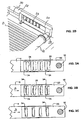
Fig. 1 is an isometric view of a solar collector, according to the present invention; -
Figs. 2A and2B are enlarged views of an embodiment of a temperature control mechanism according to the present invention, showing the mechanism in two states, and -
Figs. 3A, 3B and 3C schematically illustrate three dispositions of the control mechanism. - With specific reference now to the figures in detail, it is stressed that the particulars shown are by way of example and for purposes of illustrative discussion of the preferred embodiments of the present invention only, and are presented in the cause of providing what is believed to be the most useful and readily understood description of the principles and conceptual aspects of the invention. In this regard, no attempt is made to show structural details of the invention in more detail than is necessary for a fundamental understanding of the invention, the description taken with the drawings making apparent to those skilled in the art how the several forms of the invention may be embodied in practice.
- Referring to
Fig. 1 , there is illustrated a solar collector 2, according to the present invention, which is essentially composed of a panel unit 4 and anenclosure 6. The panel unit 4 made of plastic material, comprises at least one, or several, juxtaposed, elongated conduits 8 (Figs. 2A, 2B ) interconnected at their ends bymanifolds enclosure 6, which is sized to accommodate the width of the panel unit only with a small clearance, but the length of the panel unit with a substantial clearance, so as to allow free expansion of the panel unit, in the direction as indicated by arrow A. Themanifold 12, or the panel unit adjacent thereto, is fixed to theenclosure 6 by any suitable per-se known manner, e.g., by ahook 14, so that thermal expansion and contraction movements of the panel unit 4, take place at the side of themanifold 16. - The
enclosure 6 is further provided with at least one, preferably several,air vent mechanisms 18, the size of the venting openings being controlled with respect to the heat generated inside the enclosure. This is accomplished by operationally linking the panel unit 4 to themechanism 18, so as to effect the opening and closing of the vents' apertures as a function of the expansion and contraction linear movements of the panel unit 4. As seen inFigs. 2A ,2B, 3A, 3B and 3C , theair vent mechanism 18 includes ablock 20 slidingly coupled inside arecess 22 to an apertured section of an inner side wall of theenclosure 6. Theblock 20 hasseveral openings 24, the form and size of which can be chosen. Likewise, the form and size of theapertures 26 made in the enclosure's sidewall section, can be chosen. In the shown example, theapertures 26 are trapezoidal (Figs. 3A to 3C ), while triangular or rectangular apertures can just as well be used. Theedge 28 of themanifold 16 is attached to theblock 20 at one end portion, thereby linking the panel unit 4 to theair vent mechanism 18. If an additionalair vent mechanism 18 is provided on the same side of theenclosure 6, the twomechanisms 18 are linked by arod 30 attached at its ends to each of the mechanisms'blocks 20, so that movement ofblock 20 induced by the expansion or contraction of the panel unit 4 including themanifold 16, will cause an identical or corresponding sliding movement ofblock 20 ofmechanism 18 locatedadjacent manifold 12. - Referring now
Figs. 3A to 3C , there is illustrated, in greater detail themechanism 18 showing the section of the side wall of theenclosure 6 made with spaced-aparttrapezoidal apertures 26, theblock 20 as aligned with the apertures 32 and the cross-section of the end of themanifold 16. The direction of expansion of the panel unit 4 with themanifold 16 is indicated by arrows B. As seen inFig. 3A , at low temperatures, theopenings 24 andapertures 26 overlap. At a temperature of, say, 60° prevailing inside the enclosure 6 (Fig. 3B ), the panel unit 4 is thermally expanded to a small degree, thus sliding theblock 20 to a corresponding small degree, forming relatively small apertures 34 (Fig. 3A ). As the heat inside the enclosure rises, e.g., to 80°, the panel unit 4 further expands, themanifold 16 is further displaced and slides theblock 20 in the direction of arrows B, correspondingly enlarging the size ofapertures 34. At a temperature of e.g., 100°C inside the enclosure 6 (Fig. 3C ), theapertures 34 are at their maximal size, allowing maximal ventilation for maintaining the temperature inside the enclosure at a level not exceeding about 120°. For a more effective ventilation inside the enclosure, it is advised to form one or more simple openings (38,Fig. 1 ) at the side of the enclosure opposite theair vent mechanisms 18. - It will be evident to those skilled in the art that the invention is not limited to the details of the foregoing illustrated embodiments and that the present invention may be embodied in other specific forms without departing from the spirit or essential attributes thereof. The present embodiments are therefore to be considered in all respects as illustrative and not restrictive, the scope of the invention being indicated by the appended claims rather than by the foregoing description, and all changes which come within the meaning and range of equivalency of the claims are therefore intended to be embraced therein.
Claims (9)
- A solar collector (2) comprising:an enclosure (6) having a bottom and side wall surfaces substantially made of plastic material and a transparent top surface;at least one panel unit (4) composed of elongated conduits (8) interconnected at each end by a manifold (12,16); andsaid enclosure (6) having at least one controllable air vent mechanism (18); characterised in that said at least one panel unit (4) is movably affixed inside said enclosure (6) and sized to freely expand and contract within said enclosure (6) due to thermal changes, and in that said at least one controllable air vent mechanism is responsive to expansion and contraction of said at least one panel unit.
- The solar collector according to claim 1, wherein said enclosure (6) is quadrilateral.
- The solar collector according to claim 1 or 2, wherein the at least one panel unit is movably affixed to said enclosure (6) at, or adjacent to, one end thereof.
- The solar collector according to any one of claims 1 to 3, wherein said at least one air vent mechanism (18) is made in one of said side wall surfaces of the enclosure.
- The solar collector according to any one of claims 1 to 4, wherein said at least one air vent mechanism (18) is at least indirectly connected to a manifold (16) of said panel unit.
- The solar collector according to claim 1, wherein there are provided two air vent mechanisms (18), each located adjacent to one manifold (16) of said panel unit and being operationally, mechanically interconnected.
- The solar collector according to any one of claims 1 to 5, wherein said at least one air vent mechanism (18) comprises at least one first opening (26) made in the side surface of said enclosure (6) and at least a second opening (24) made in a block (20) slidingly movable in relation to said at least one first opening (26).
- The solar collector according to claim 7, wherein one of said manifolds (16) is at least indirectly connected to said sliding block (20).
- The solar collector according to any one of claims 1 to 8, further comprising at least one opening made in a side surface of said enclosure (6) opposite to said at least one air vent mechanism (18).
Applications Claiming Priority (2)
| Application Number | Priority Date | Filing Date | Title |
|---|---|---|---|
| IL183052A IL183052A (en) | 2007-05-08 | 2007-05-08 | Enclosure for a solar collector |
| PCT/IL2008/000640 WO2008136006A2 (en) | 2007-05-08 | 2008-05-07 | Enclosure for a solar collector |
Publications (2)
| Publication Number | Publication Date |
|---|---|
| EP2142859A2 EP2142859A2 (en) | 2010-01-13 |
| EP2142859B1 true EP2142859B1 (en) | 2016-03-23 |
Family
ID=39924995
Family Applications (1)
| Application Number | Title | Priority Date | Filing Date |
|---|---|---|---|
| EP08738341.0A Not-in-force EP2142859B1 (en) | 2007-05-08 | 2008-05-07 | Enclosure for a solar collector |
Country Status (6)
| Country | Link |
|---|---|
| US (1) | US20100132764A1 (en) |
| EP (1) | EP2142859B1 (en) |
| BR (1) | BRPI0810351A2 (en) |
| IL (1) | IL183052A (en) |
| MX (1) | MX2009012175A (en) |
| WO (1) | WO2008136006A2 (en) |
Families Citing this family (7)
| Publication number | Priority date | Publication date | Assignee | Title |
|---|---|---|---|---|
| WO2011094770A2 (en) * | 2010-01-29 | 2011-08-04 | Aqua Filter (Pty) Ltd | Solar heat collecting device |
| IL212303A (en) * | 2011-04-13 | 2013-09-30 | Magen Eco Energy A C S Ltd | Solar collector |
| WO2013055370A1 (en) * | 2011-10-14 | 2013-04-18 | Empire Technology Development Llc | Air exchanging thermally responsive wall panels and methods |
| JP2013160454A (en) * | 2012-02-06 | 2013-08-19 | Mitsubishi Plastics Inc | Solar collector |
| DE202012007717U1 (en) * | 2012-08-10 | 2013-11-11 | Robert Bosch Gmbh | Solar panel housing and solar panel |
| DE102014225531A1 (en) * | 2014-12-11 | 2016-06-16 | Robert Bosch Gmbh | Collector aeration device and collector |
| USD815027S1 (en) * | 2016-07-15 | 2018-04-10 | Sunstream Technology, Inc. | Enclosure for portable solar charger |
Family Cites Families (13)
| Publication number | Priority date | Publication date | Assignee | Title |
|---|---|---|---|---|
| US3943911A (en) * | 1974-05-31 | 1976-03-16 | Yu Ying Nien | Solar heat collector |
| US4046134A (en) * | 1976-08-26 | 1977-09-06 | Xonics, Inc. | Solar heater with automatic venting |
| US4278072A (en) * | 1978-08-21 | 1981-07-14 | Rykal Solar Corporation | Forced air solar heating system |
| US4303059A (en) * | 1979-09-06 | 1981-12-01 | Energy Design Corporation | Apparatus for solar energy collection |
| JPS56162350A (en) * | 1980-04-30 | 1981-12-14 | Kaaruson Kuraaku Piitaa | Heating panel |
| US4503840A (en) * | 1981-07-30 | 1985-03-12 | Burton Energy And Solar Technology Inc. | Solar energy and venting systems |
| US4397305A (en) * | 1981-10-14 | 1983-08-09 | Solaroi, Inc. | Solar heating panel |
| US4423718A (en) * | 1982-02-24 | 1984-01-03 | Garrison John D | Solar collector panel and energy shield |
| US4471758A (en) * | 1982-08-13 | 1984-09-18 | Jennings Donald E | House siding solar panel |
| JPS5981448A (en) * | 1982-11-01 | 1984-05-11 | Matsushita Electric Ind Co Ltd | Solar heat collector |
| EP1264352A1 (en) * | 2000-03-16 | 2002-12-11 | Max Roth | Energy element |
| DE20105162U1 (en) * | 2001-03-23 | 2001-06-13 | Schüco International KG, 33609 Bielefeld | Solar panel and absorber holder |
| DE202006013263U1 (en) * | 2006-08-24 | 2006-12-07 | Haticon Gmbh | Solar collector with housing that can be vented, e.g. for solar roof, has housing having framework and covered by thermal insulation and having radiation-permeable front cover |
-
2007
- 2007-05-08 IL IL183052A patent/IL183052A/en active IP Right Grant
-
2008
- 2008-05-07 BR BRPI0810351A patent/BRPI0810351A2/en not_active IP Right Cessation
- 2008-05-07 WO PCT/IL2008/000640 patent/WO2008136006A2/en not_active Ceased
- 2008-05-07 MX MX2009012175A patent/MX2009012175A/en not_active Application Discontinuation
- 2008-05-07 EP EP08738341.0A patent/EP2142859B1/en not_active Not-in-force
- 2008-05-07 US US12/599,281 patent/US20100132764A1/en not_active Abandoned
Also Published As
| Publication number | Publication date |
|---|---|
| US20100132764A1 (en) | 2010-06-03 |
| IL183052A (en) | 2011-04-28 |
| WO2008136006A2 (en) | 2008-11-13 |
| WO2008136006A3 (en) | 2009-05-28 |
| BRPI0810351A2 (en) | 2016-11-22 |
| IL183052A0 (en) | 2007-09-20 |
| MX2009012175A (en) | 2009-12-01 |
| EP2142859A2 (en) | 2010-01-13 |
Similar Documents
| Publication | Publication Date | Title |
|---|---|---|
| US20100132764A1 (en) | Enclosure for a Solar Collector | |
| US4150659A (en) | Apparatus for preventing high temperatures in a glazed solar collector | |
| EP2520169B1 (en) | Baking oven door and baking oven | |
| US4422443A (en) | Solar collector | |
| US4058109A (en) | Solar heating and insulating apparatus | |
| KR20060016336A (en) | Hinged Structure of Air Vent Grille | |
| EP2387694B1 (en) | Solar thermal collecting system | |
| US4219009A (en) | Vented solar panel | |
| KR101421518B1 (en) | heating tent for indoor | |
| US9016270B2 (en) | Window mounting for thermal expansion in an oven appliance | |
| RU2012153576A (en) | A WINDOW HAVING A REPLACEABLE INTERFACE AND A METHOD FOR ITS MANUFACTURE | |
| US10371247B2 (en) | Transmission tunnel encapsulation | |
| KR20130097897A (en) | Door frame having heat device | |
| JP2002309689A (en) | Wall structure for heat insulation and heat transfer | |
| KR102093046B1 (en) | Solar collector having automatic opening and closing means | |
| JP3050499B2 (en) | Heat storage structure | |
| CN208042306U (en) | Control box for heater and heater | |
| JP4862380B2 (en) | Thermal insulation shutter | |
| KR200418541Y1 (en) | Heating device of double glazing for building | |
| KR102030502B1 (en) | Tent | |
| US4189988A (en) | Insulation and ventilation system for mobile homes | |
| JP7162212B2 (en) | Rooftop snow melting device | |
| JP2011032769A (en) | Sunroom and building | |
| CN209538432U (en) | A kind of integrated heat-insulation wall plate structure of exterior-wall heat insulation construction | |
| RU97101668A (en) | ELECTRIC HEATER |
Legal Events
| Date | Code | Title | Description |
|---|---|---|---|
| PUAI | Public reference made under article 153(3) epc to a published international application that has entered the european phase |
Free format text: ORIGINAL CODE: 0009012 |
|
| 17P | Request for examination filed |
Effective date: 20090929 |
|
| AK | Designated contracting states |
Kind code of ref document: A2 Designated state(s): AT BE BG CH CY CZ DE DK EE ES FI FR GB GR HR HU IE IS IT LI LT LU LV MC MT NL NO PL PT RO SE SI SK TR |
|
| DAX | Request for extension of the european patent (deleted) | ||
| GRAP | Despatch of communication of intention to grant a patent |
Free format text: ORIGINAL CODE: EPIDOSNIGR1 |
|
| INTG | Intention to grant announced |
Effective date: 20150922 |
|
| GRAS | Grant fee paid |
Free format text: ORIGINAL CODE: EPIDOSNIGR3 |
|
| INTG | Intention to grant announced |
Effective date: 20160121 |
|
| GRAA | (expected) grant |
Free format text: ORIGINAL CODE: 0009210 |
|
| AK | Designated contracting states |
Kind code of ref document: B1 Designated state(s): AT BE BG CH CY CZ DE DK EE ES FI FR GB GR HR HU IE IS IT LI LT LU LV MC MT NL NO PL PT RO SE SI SK TR |
|
| REG | Reference to a national code |
Ref country code: GB Ref legal event code: FG4D |
|
| REG | Reference to a national code |
Ref country code: CH Ref legal event code: EP |
|
| REG | Reference to a national code |
Ref country code: AT Ref legal event code: REF Ref document number: 783558 Country of ref document: AT Kind code of ref document: T Effective date: 20160415 |
|
| REG | Reference to a national code |
Ref country code: IE Ref legal event code: FG4D |
|
| REG | Reference to a national code |
Ref country code: DE Ref legal event code: R096 Ref document number: 602008043042 Country of ref document: DE |
|
| REG | Reference to a national code |
Ref country code: FR Ref legal event code: PLFP Year of fee payment: 9 |
|
| REG | Reference to a national code |
Ref country code: LT Ref legal event code: MG4D |
|
| REG | Reference to a national code |
Ref country code: NL Ref legal event code: MP Effective date: 20160323 |
|
| PG25 | Lapsed in a contracting state [announced via postgrant information from national office to epo] |
Ref country code: FI Free format text: LAPSE BECAUSE OF FAILURE TO SUBMIT A TRANSLATION OF THE DESCRIPTION OR TO PAY THE FEE WITHIN THE PRESCRIBED TIME-LIMIT Effective date: 20160323 Ref country code: NO Free format text: LAPSE BECAUSE OF FAILURE TO SUBMIT A TRANSLATION OF THE DESCRIPTION OR TO PAY THE FEE WITHIN THE PRESCRIBED TIME-LIMIT Effective date: 20160623 Ref country code: GR Free format text: LAPSE BECAUSE OF FAILURE TO SUBMIT A TRANSLATION OF THE DESCRIPTION OR TO PAY THE FEE WITHIN THE PRESCRIBED TIME-LIMIT Effective date: 20160624 |
|
| REG | Reference to a national code |
Ref country code: AT Ref legal event code: MK05 Ref document number: 783558 Country of ref document: AT Kind code of ref document: T Effective date: 20160323 |
|
| PG25 | Lapsed in a contracting state [announced via postgrant information from national office to epo] |
Ref country code: LV Free format text: LAPSE BECAUSE OF FAILURE TO SUBMIT A TRANSLATION OF THE DESCRIPTION OR TO PAY THE FEE WITHIN THE PRESCRIBED TIME-LIMIT Effective date: 20160323 Ref country code: LT Free format text: LAPSE BECAUSE OF FAILURE TO SUBMIT A TRANSLATION OF THE DESCRIPTION OR TO PAY THE FEE WITHIN THE PRESCRIBED TIME-LIMIT Effective date: 20160323 Ref country code: SE Free format text: LAPSE BECAUSE OF FAILURE TO SUBMIT A TRANSLATION OF THE DESCRIPTION OR TO PAY THE FEE WITHIN THE PRESCRIBED TIME-LIMIT Effective date: 20160323 Ref country code: BE Free format text: LAPSE BECAUSE OF NON-PAYMENT OF DUE FEES Effective date: 20160531 Ref country code: NL Free format text: LAPSE BECAUSE OF FAILURE TO SUBMIT A TRANSLATION OF THE DESCRIPTION OR TO PAY THE FEE WITHIN THE PRESCRIBED TIME-LIMIT Effective date: 20160323 |
|
| PG25 | Lapsed in a contracting state [announced via postgrant information from national office to epo] |
Ref country code: EE Free format text: LAPSE BECAUSE OF FAILURE TO SUBMIT A TRANSLATION OF THE DESCRIPTION OR TO PAY THE FEE WITHIN THE PRESCRIBED TIME-LIMIT Effective date: 20160323 Ref country code: PL Free format text: LAPSE BECAUSE OF FAILURE TO SUBMIT A TRANSLATION OF THE DESCRIPTION OR TO PAY THE FEE WITHIN THE PRESCRIBED TIME-LIMIT Effective date: 20160323 Ref country code: IS Free format text: LAPSE BECAUSE OF FAILURE TO SUBMIT A TRANSLATION OF THE DESCRIPTION OR TO PAY THE FEE WITHIN THE PRESCRIBED TIME-LIMIT Effective date: 20160723 |
|
| PG25 | Lapsed in a contracting state [announced via postgrant information from national office to epo] |
Ref country code: CZ Free format text: LAPSE BECAUSE OF FAILURE TO SUBMIT A TRANSLATION OF THE DESCRIPTION OR TO PAY THE FEE WITHIN THE PRESCRIBED TIME-LIMIT Effective date: 20160323 Ref country code: PT Free format text: LAPSE BECAUSE OF FAILURE TO SUBMIT A TRANSLATION OF THE DESCRIPTION OR TO PAY THE FEE WITHIN THE PRESCRIBED TIME-LIMIT Effective date: 20160725 Ref country code: RO Free format text: LAPSE BECAUSE OF FAILURE TO SUBMIT A TRANSLATION OF THE DESCRIPTION OR TO PAY THE FEE WITHIN THE PRESCRIBED TIME-LIMIT Effective date: 20160323 Ref country code: ES Free format text: LAPSE BECAUSE OF FAILURE TO SUBMIT A TRANSLATION OF THE DESCRIPTION OR TO PAY THE FEE WITHIN THE PRESCRIBED TIME-LIMIT Effective date: 20160323 Ref country code: AT Free format text: LAPSE BECAUSE OF FAILURE TO SUBMIT A TRANSLATION OF THE DESCRIPTION OR TO PAY THE FEE WITHIN THE PRESCRIBED TIME-LIMIT Effective date: 20160323 Ref country code: SK Free format text: LAPSE BECAUSE OF FAILURE TO SUBMIT A TRANSLATION OF THE DESCRIPTION OR TO PAY THE FEE WITHIN THE PRESCRIBED TIME-LIMIT Effective date: 20160323 |
|
| PG25 | Lapsed in a contracting state [announced via postgrant information from national office to epo] |
Ref country code: IT Free format text: LAPSE BECAUSE OF FAILURE TO SUBMIT A TRANSLATION OF THE DESCRIPTION OR TO PAY THE FEE WITHIN THE PRESCRIBED TIME-LIMIT Effective date: 20160323 Ref country code: BE Free format text: LAPSE BECAUSE OF FAILURE TO SUBMIT A TRANSLATION OF THE DESCRIPTION OR TO PAY THE FEE WITHIN THE PRESCRIBED TIME-LIMIT Effective date: 20160323 Ref country code: LU Free format text: LAPSE BECAUSE OF FAILURE TO SUBMIT A TRANSLATION OF THE DESCRIPTION OR TO PAY THE FEE WITHIN THE PRESCRIBED TIME-LIMIT Effective date: 20160507 |
|
| REG | Reference to a national code |
Ref country code: CH Ref legal event code: PL |
|
| REG | Reference to a national code |
Ref country code: DE Ref legal event code: R097 Ref document number: 602008043042 Country of ref document: DE |
|
| PLBE | No opposition filed within time limit |
Free format text: ORIGINAL CODE: 0009261 |
|
| STAA | Information on the status of an ep patent application or granted ep patent |
Free format text: STATUS: NO OPPOSITION FILED WITHIN TIME LIMIT |
|
| PG25 | Lapsed in a contracting state [announced via postgrant information from national office to epo] |
Ref country code: DK Free format text: LAPSE BECAUSE OF FAILURE TO SUBMIT A TRANSLATION OF THE DESCRIPTION OR TO PAY THE FEE WITHIN THE PRESCRIBED TIME-LIMIT Effective date: 20160323 Ref country code: CH Free format text: LAPSE BECAUSE OF NON-PAYMENT OF DUE FEES Effective date: 20160531 Ref country code: LI Free format text: LAPSE BECAUSE OF NON-PAYMENT OF DUE FEES Effective date: 20160531 |
|
| REG | Reference to a national code |
Ref country code: IE Ref legal event code: MM4A |
|
| PG25 | Lapsed in a contracting state [announced via postgrant information from national office to epo] |
Ref country code: BG Free format text: LAPSE BECAUSE OF FAILURE TO SUBMIT A TRANSLATION OF THE DESCRIPTION OR TO PAY THE FEE WITHIN THE PRESCRIBED TIME-LIMIT Effective date: 20160623 |
|
| 26N | No opposition filed |
Effective date: 20170102 |
|
| GBPC | Gb: european patent ceased through non-payment of renewal fee |
Effective date: 20160623 |
|
| REG | Reference to a national code |
Ref country code: FR Ref legal event code: PLFP Year of fee payment: 10 |
|
| PG25 | Lapsed in a contracting state [announced via postgrant information from national office to epo] |
Ref country code: GB Free format text: LAPSE BECAUSE OF NON-PAYMENT OF DUE FEES Effective date: 20160623 Ref country code: SI Free format text: LAPSE BECAUSE OF FAILURE TO SUBMIT A TRANSLATION OF THE DESCRIPTION OR TO PAY THE FEE WITHIN THE PRESCRIBED TIME-LIMIT Effective date: 20160323 Ref country code: IE Free format text: LAPSE BECAUSE OF NON-PAYMENT OF DUE FEES Effective date: 20160507 |
|
| REG | Reference to a national code |
Ref country code: DE Ref legal event code: R079 Ref document number: 602008043042 Country of ref document: DE Free format text: PREVIOUS MAIN CLASS: F24J0002460000 Ipc: F24S0040000000 |
|
| REG | Reference to a national code |
Ref country code: FR Ref legal event code: PLFP Year of fee payment: 11 |
|
| PG25 | Lapsed in a contracting state [announced via postgrant information from national office to epo] |
Ref country code: CY Free format text: LAPSE BECAUSE OF FAILURE TO SUBMIT A TRANSLATION OF THE DESCRIPTION OR TO PAY THE FEE WITHIN THE PRESCRIBED TIME-LIMIT Effective date: 20160323 Ref country code: HU Free format text: LAPSE BECAUSE OF FAILURE TO SUBMIT A TRANSLATION OF THE DESCRIPTION OR TO PAY THE FEE WITHIN THE PRESCRIBED TIME-LIMIT; INVALID AB INITIO Effective date: 20080507 |
|
| PG25 | Lapsed in a contracting state [announced via postgrant information from national office to epo] |
Ref country code: MT Free format text: LAPSE BECAUSE OF NON-PAYMENT OF DUE FEES Effective date: 20160531 Ref country code: HR Free format text: LAPSE BECAUSE OF FAILURE TO SUBMIT A TRANSLATION OF THE DESCRIPTION OR TO PAY THE FEE WITHIN THE PRESCRIBED TIME-LIMIT Effective date: 20160323 Ref country code: MC Free format text: LAPSE BECAUSE OF FAILURE TO SUBMIT A TRANSLATION OF THE DESCRIPTION OR TO PAY THE FEE WITHIN THE PRESCRIBED TIME-LIMIT Effective date: 20160323 Ref country code: TR Free format text: LAPSE BECAUSE OF FAILURE TO SUBMIT A TRANSLATION OF THE DESCRIPTION OR TO PAY THE FEE WITHIN THE PRESCRIBED TIME-LIMIT Effective date: 20160323 |
|
| PGFP | Annual fee paid to national office [announced via postgrant information from national office to epo] |
Ref country code: DE Payment date: 20180524 Year of fee payment: 11 |
|
| PGFP | Annual fee paid to national office [announced via postgrant information from national office to epo] |
Ref country code: FR Payment date: 20180523 Year of fee payment: 11 |
|
| REG | Reference to a national code |
Ref country code: DE Ref legal event code: R119 Ref document number: 602008043042 Country of ref document: DE |
|
| PG25 | Lapsed in a contracting state [announced via postgrant information from national office to epo] |
Ref country code: DE Free format text: LAPSE BECAUSE OF NON-PAYMENT OF DUE FEES Effective date: 20191203 |
|
| PG25 | Lapsed in a contracting state [announced via postgrant information from national office to epo] |
Ref country code: FR Free format text: LAPSE BECAUSE OF NON-PAYMENT OF DUE FEES Effective date: 20190531 |