EP2142389B1 - Apparatus and method for adaptive temperature compensation in a tyre pressure monitoring system - Google Patents
Apparatus and method for adaptive temperature compensation in a tyre pressure monitoring system Download PDFInfo
- Publication number
- EP2142389B1 EP2142389B1 EP08716718.5A EP08716718A EP2142389B1 EP 2142389 B1 EP2142389 B1 EP 2142389B1 EP 08716718 A EP08716718 A EP 08716718A EP 2142389 B1 EP2142389 B1 EP 2142389B1
- Authority
- EP
- European Patent Office
- Prior art keywords
- temperature
- reference temperature
- ambient temperature
- value
- determining
- Prior art date
- Legal status (The legal status is an assumption and is not a legal conclusion. Google has not performed a legal analysis and makes no representation as to the accuracy of the status listed.)
- Active
Links
Images




Classifications
-
- B—PERFORMING OPERATIONS; TRANSPORTING
- B60—VEHICLES IN GENERAL
- B60C—VEHICLE TYRES; TYRE INFLATION; TYRE CHANGING; CONNECTING VALVES TO INFLATABLE ELASTIC BODIES IN GENERAL; DEVICES OR ARRANGEMENTS RELATED TO TYRES
- B60C23/00—Devices for measuring, signalling, controlling, or distributing tyre pressure or temperature, specially adapted for mounting on vehicles; Arrangement of tyre inflating devices on vehicles, e.g. of pumps or of tanks; Tyre cooling arrangements
- B60C23/02—Signalling devices actuated by tyre pressure
- B60C23/04—Signalling devices actuated by tyre pressure mounted on the wheel or tyre
- B60C23/0408—Signalling devices actuated by tyre pressure mounted on the wheel or tyre transmitting the signals by non-mechanical means from the wheel or tyre to a vehicle body mounted receiver
Definitions
- the present invention relates to tyre pressure monitoring systems and in particular to adaptive temperature compensation in tyre pressure monitoring systems.
- Tyre pressure monitoring systems are well known.
- a simple method for monitoring tyre pressure is to monitor the absolute pressure within a tyre and, if it falls below a threshold, to issue a warning.
- this does not allow for variations in tyre temperature that occur while the vehicle is in motion (the temperature, and therefore the pressure, inside a tyre increases in a substantially linear manner during use of the vehicle).
- one aspect of the invention provides an apparatus for performing temperature compensation in a tyre pressure monitoring system arranged to measure the pressure and temperature of fluid within at least one tyre, the apparatus being arranged to adjust the measured tyre pressure with respect to the value of a reference temperature, wherein the apparatus is cooperable with means for determining ambient temperature, the apparatus being arranged to adjust the reference temperature in response to determining that ambient temperature has changed.
- the apparatus increases the reference temperature in response to determining that ambient temperature has increased and decreases the reference temperature in response to determining that ambient temperature has decreased.
- the rate at which the reference temperature is increased is higher than the rate at which the reference is decreased.
- the apparatus sets the reference temperature to, or substantially to, the measured ambient temperature in response to determining that the ambient temperature exceeds the reference temperature.
- this is performed substantially immediately after the determination is made, or within a time period preferably not exceeding approximately 20 minutes.
- the preferred apparatus in response to determining that the current ambient temperature is less than the reference temperature, sets the reference temperature to an average of the current ambient temperature and at least one previous ambient temperature and/or the current reference temperature.
- the reference temperature may be calculated as a rolling average of the current ambient temperature and a plurality of previous ambient temperatures.
- the new reference temperature may be calculated as a weighted average of the current reference temperature and the current ambient temperature.
- a new value for the reference temperature may be calculated by averaging ambient temperature values over n time periods t, where the ambient temperature and a new value for the reference temperature are calculated every time period t.
- the reference temperature may be calculated as a rolling average of ambient temperature values taken over a 24 hour period of operation, wherein a new value for the reference temperature is calculated every hour.
- a second aspect of the invention provides a tyre pressure monitoring system arranged to measure the pressure and temperature of fluid within at least one tyre, the system including apparatus for performing temperature compensation, the apparatus being arranged to adjust the measured tyre pressure with respect to the value of a reference temperature, wherein the apparatus is cooperable with means for determining ambient temperature, the apparatus being arranged to adjust the reference temperature in response to determining that ambient temperature has changed.
- a third aspect of the invention provides a method of performing temperature compensation in a tyre pressure monitoring system arranged to measure the pressure and temperature of fluid within at least one tyre and to adjust the measured tyre pressure with respect to the value of a reference temperature, the method comprising: determining ambient temperature; and, in response to determining that ambient temperature has changed, adjusting the reference temperature.
- a fourth aspect of the invention provides a computer program product comprising computer usable code stored on a computer usable medium, the computer program code being arranged to cause a computer to perform the method of the third aspect of the invention.
- Active adaptation of the reference temperature insures that temperature compensation is matched to the ambient conditions of the drive so that system sensitivity is maintained closer to design intended levels in all seasons.
- a typical tyre pressure monitoring system for measuring the pressure of a fluid (typically air) in a tyre.
- the TPMS 10 usually comprises a respective sensor unit 12 for each tyre bearing wheel (not shown) of the vehicle (not shown) in which it is installed.
- the vehicle is assumed to have four wheels and the sensor units are designated as Left Front (LF), Right Front (RF), Right Rear (RR) and Left Rear (LR) corresponding to the position of the wheel on which they are mounted.
- Each sensor unit 12 includes an appropriate sensor device (e.g. a piezo-electric pressure sensor (not shown)) for measuring fluid (typically air) pressure within the respective tyre.
- the sensor units 12 also include a respective temperature sensor (not shown) for measuring the temperature of the fluid within the respective tyre.
- the TPMS 10 includes a receiver unit 14 arranged to receive signals 16 from the sensor units 12 indicating the measured tyre pressure (RTP) and/or temperature (RTT).
- the sensor units 12 are typically wheel mounted, the receiver unit 14 being located remotely from the sensor units 12 on some other part of the vehicle.
- the sensor units 12 and receiver 14 communicate wirelessly using for example an RF (radio frequency) link.
- the receiver 14 and each sensor unit 12 has a respective RF transmitter and/or receiver as required.
- the receiver 14 includes a control apparatus, or unit, 18 comprising a programmable processing device, usually a microprocessor or microcontroller.
- the control unit 18 analyses the information received from the sensor units 12 and transmits corresponding information to a display unit 20 which is usually provided on the vehicle's instrument panel.
- the control unit 18 may send a respective temperature compensated pressure (TCP) value signal 22 and, if warranted, a respective temperature compensated pressure warning (TCW) signal 24 to the display unit 20 for each wheel.
- TCP temperature compensated pressure
- TCW temperature compensated pressure warning
- the control unit 18 is also arranged to receive a signal 28 indicating the vehicle's ambient, or outside, temperature. This may be obtained from any convenient vehicle temperature sensor 26, for example the temperature sensor used by an air conditioning system.
- P TC is the temperature compensated pressure value
- P meas is the measured tyre pressure value
- T meas is the measured tyre temperature value
- T ref is the reference temperature.
- the constant 273.15 effects a conversion from Celsuis to Kelvin
- the constant 1.01 is included on the assumption that pressure is measured in bar.
- the reference temperature, Tref is fixed to a nominal value, for example 20°C.
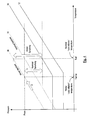
- Figure 2 shows an example of how a tyre may be filled in relatively warm conditions, e.g. during summer, in a system where a fixed reference temperature T ref is used. It is assumed that the tyre is filled to the placard, or nominal, level, P nom , at an ambient temperature that is higher than the chosen reference T ref .
- Figure 2 also shows a pressure warning threshold 30, a pressure alarm threshold 32, a nominal isochore 34 (indicating how tyre pressure will vary with tyre temperature at an assumed ambient temperature of T ref ) and a summer isochore 36 (indicating how tyre pressure will vary with tyre temperature at an ambient temperature of T summer ).
- Temperature compensation in accordance with equation [1] adjusts (in this case reduces) the measured tyre pressure in proportion to the difference between T ref and the actual fill temperature T summer (e.g. 0.11 Bar per 10C difference at a fill pressure of 2 Bar). This leads to a reduced distance between the warning threshold 30 and the temperature compensated pressure and, hence, increased probability of false warnings, i.e. increased sensitivity.
- Figure 4 shows an example of how a tyre may be filled in relatively cold conditions, e.g. during winter, in a system where a fixed reference temperature T ref is used. It is assumed that the tyre is filled to the placard or nominal level, P nom , at an ambient temperature that is lower than the chosen reference T ref .
- Figure 4 also shows a pressure warning threshold 30, a pressure alarm threshold 32, a nominal isochore 34 (indicating how tyre pressure will vary with tyre temperature at an assumed ambient temperature of T ref ) and a winter isochore 38 (indicating how tyre pressure will vary with tyre temperature at an ambient temperature of T winter )
- Temperature compensation in accordance with equation [1] adjusts (in this case increases) the measured tyre pressure in proportion to the difference between T ref and the actual fill temperature T winter (e.g. 0.11 Bar per 10C difference at a fill pressure of 2 Bar). This leads to an increased distance between the warning threshold 30 and the temperature compensated pressure and, hence, reduced sensitivity.
- Figures 3 and 5 show the effect of adapting the reference temperature in the context of the summer scenario illustrated in Figure 2 and the winter scenario illustrated in Figure 4 , respectively.
- the adapted alert thresholds 30', 32' are effectively shifted positively (summer) or negatively (winter) along the temperature axis to maintain the system sensitivity at the nominal level, the size of the shift being dependent on the value of the ambient temperature.
- the thresholds 30, 32 are moved to the respective ambient temperature T summer and T winter such that the required sensitivity is maintained.
- the ambient temperature is calculated as a moving average of the past n ambient temperature samples, as is described in more detail below.
- the TPMS 10, or more particularly the control unit 18 is initialised with a default, or nominal, reference temperature T ref , which may for example be 20°C. Subsequently, and preferably over the lifetime of the vehicle or TPMS 10, the control unit 14 adjusts T ref depending on a measured or calculated value for the vehicle's ambient temperature. Preferably, the value for ambient temperature is only measured or calculated for this purpose when the vehicle's engine is running and, more preferably, only when the vehicle is moving. In the preferred embodiment, T ref is only adjusted when the vehicle's engine is running and, more preferably, only when the vehicle is moving.
- control unit 18 In the preferred embodiment, three values of average outside or ambient air temperature are maintained by the control unit 18:
- control unit 18 it is not necessary for the control unit 18 to maintain three separate average values for ambient temperature.
- only one average value need be maintained, the value of which is used to determine T ref . It is preferred that this average value be a rolling average value at least when ambient temperature is falling with respect to T ref .
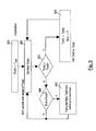
- T ref is initialised [601] to, for example, a default setting.
- T(24hr) is calculated [602] which, initially, may involve setting the value of T(24hr) to the initial value of T ref .
- T(ots) is calculated [603] and, at the end of every T(ots) sampling period, the value of T(ots) is compared against the current value ofT(ref) [604].
- T(ots) is lower than (or equal to) the current T(ref)
- T(ots) is stored and the T(ots) sampling period restarts. While T(ots) at the end of each sampling period continues to be less than T ref the cycle of sample and store continues until one hour has elapsed [605, 606, 603, 604]. At this point, the average temperature for the hour is calculated to give T(hrly) for that hour [607]. T(24hr) is then updated using the newly calculated T(hrly) giving a new T ref . Hence, while T(ots) is lower than T ref , the algorithm updates T ref on a hourly basis using T(hrly) for the previous hour. This is preferably achieved using a rolling average calculation. Thus when the outside air temperature is falling relative to T ref , the value of T ref is updated hourly and falls slowly towards the reduced average outside air temperature.
- T(ots) at the end of the sampling period is higher than the current T ref value, T(ots) is immediately adopted as the new T ref [608].
- T(24hr) Two preferred averaging mechanisms for calculating T(24hr) are envisaged.
- the first calculates a full moving average of a plurality (24 in this example) of ambient temperature values (T(hrly) in this example), and is illustrated in Figures 7 and 8 .
- T(ots) is obtained and compared to T ref [702, 703]. While T(ots) remains less than T ref , successive values of T(ots) are stored in order to calculate T(hrly) [702, 703, 704].
- T(ots) remains less than T ref for the specified period (1 hour) then a new T ref is calculated [705] using a moving average of values for T(hrly), as is illustrated in more detail in Figure 8 which shows an implementation of module 705.
- T(hrly) is calculated, it is stored in order in the array [802].
- a new value for T(24hr), and therefore T ref is calculated as the average of the values stored in the array [803, 804].
- the values for T(hrly) calculated in the previous 24 hours are stored in any convenient manner and T(24hr) is calculated as the average of these values.
- T ref falls to a new lower outside air temperature in exactly 24 hours of accumulated driving, or operation.
- T ref and all of the values of the T(24hr) array are immediately set to T(ots) [706]
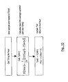
- new T ref is calculated by multiplying current T ref by n-1 , adding current T(hrly) to the result and then dividing by n , where n is the number of samples over which the reference temperature is being averaged.
- factors 23 and 24 included in equation [2] are not critical to the invention.
- T(ots) is obtained and compared to T ref [902, 903]. While T(ots) remains less than T ref , successive values of T(ots) are stored in order to calculate T(hrly) [902, 903, 904]. If T(ots) remains less than T ref for the specified period (1 hour) then a new T ref is calculated [905] using equation [2], as is illustrated in more detail in Figure 10 .
- Time to converge to new average outside air temperature for this algorithm is 100 hours (for a weighting of 23 in equation [2]).
- T ref and T(24hr) are immediately set to T(ots) [906].
- an array is not used. Instead the starting point is a single value for T(ots) which is modified periodically, e.g. hourly, using the average temperature for the previous period (e.g. hour). The advantage of this arrangement is that there is only a requirement to hold one value.
- the ambient temperature is determined every five minutes by an average of samples taken every minute, an average ambient temperature value is determined for each hour, and a new value for the reference temperature is determined every hour by an average taken over a 24 hour period. It will be understood that these time periods are provided by way of example and that, in alternative embodiments, each of the aforesaid periods may be reduced or increased independently of the other.
- the techniques presented herein cause the reference temperature to be adjusted in accordance with ambient temperature in order that the sensitivity of the TPMS 10 can be maintained at a desired level. It is noted in particular, that in the preferred embodiment, the rate at which the reference temperature is raised in response to the determination that ambient temperature is higher than the reference temperature is faster (preferably an instant adjustment to the level of the ambient temperature (instant meaning at the next available opportunity which will depend on the temperature averaging period)) than the rate at which the reference temperature is lowered in response to the determination that ambient temperature is lower than the reference temperature. This arrangement significantly reduces the occurrence of false detections. This is an important commercial consideration since consumers tend to find false detections particularly irksome.
Landscapes
- Engineering & Computer Science (AREA)
- Mechanical Engineering (AREA)
- Measuring Fluid Pressure (AREA)
Description
- The present invention relates to tyre pressure monitoring systems and in particular to adaptive temperature compensation in tyre pressure monitoring systems.
- Tyre pressure monitoring systems (TPMS) are well known. A simple method for monitoring tyre pressure is to monitor the absolute pressure within a tyre and, if it falls below a threshold, to issue a warning. However, this does not allow for variations in tyre temperature that occur while the vehicle is in motion (the temperature, and therefore the pressure, inside a tyre increases in a substantially linear manner during use of the vehicle).
- It is known to perform temperature compensated tyre pressure monitoring. This involves using Boyle's Law to adjust the absolute, or raw, measured tyre pressure and the measured temperature of the air inside the tyre with respect to a reference temperature. Conventionally, the reference temperature is fixed and does not take into account variations in ambient temperature, like in document
EP 1384 604 , according to therespective preamble - It would be desirable to mitigate these problems.
- Accordingly, one aspect of the invention provides an apparatus for performing temperature compensation in a tyre pressure monitoring system arranged to measure the pressure and temperature of fluid within at least one tyre, the apparatus being arranged to adjust the measured tyre pressure with respect to the value of a reference temperature, wherein the apparatus is cooperable with means for determining ambient temperature, the apparatus being arranged to adjust the reference temperature in response to determining that ambient temperature has changed.
- More particularly, the apparatus increases the reference temperature in response to determining that ambient temperature has increased and decreases the reference temperature in response to determining that ambient temperature has decreased. Advantageously, the rate at which the reference temperature is increased is higher than the rate at which the reference is decreased.
- In preferred embodiments, the apparatus sets the reference temperature to, or substantially to, the measured ambient temperature in response to determining that the ambient temperature exceeds the reference temperature. Advantageously, this is performed substantially immediately after the determination is made, or within a time period preferably not exceeding approximately 20 minutes.
- The preferred apparatus, in response to determining that the current ambient temperature is less than the reference temperature, sets the reference temperature to an average of the current ambient temperature and at least one previous ambient temperature and/or the current reference temperature. For example, the reference temperature may be calculated as a rolling average of the current ambient temperature and a plurality of previous ambient temperatures. Alternatively, the new reference temperature may be calculated as a weighted average of the current reference temperature and the current ambient temperature.
- In general, when the current ambient temperature is less than the reference temperature, a new value for the reference temperature may be calculated by averaging ambient temperature values over n time periods t, where the ambient temperature and a new value for the reference temperature are calculated every time period t. By way of example, the reference temperature may be calculated as a rolling average of ambient temperature values taken over a 24 hour period of operation, wherein a new value for the reference temperature is calculated every hour.
- A second aspect of the invention provides a tyre pressure monitoring system arranged to measure the pressure and temperature of fluid within at least one tyre, the system including apparatus for performing temperature compensation, the apparatus being arranged to adjust the measured tyre pressure with respect to the value of a reference temperature, wherein the apparatus is cooperable with means for determining ambient temperature, the apparatus being arranged to adjust the reference temperature in response to determining that ambient temperature has changed.
- A third aspect of the invention provides a method of performing temperature compensation in a tyre pressure monitoring system arranged to measure the pressure and temperature of fluid within at least one tyre and to adjust the measured tyre pressure with respect to the value of a reference temperature, the method comprising: determining ambient temperature; and, in response to determining that ambient temperature has changed, adjusting the reference temperature.
- A fourth aspect of the invention provides a computer program product comprising computer usable code stored on a computer usable medium, the computer program code being arranged to cause a computer to perform the method of the third aspect of the invention.
- Active adaptation of the reference temperature insures that temperature compensation is matched to the ambient conditions of the drive so that system sensitivity is maintained closer to design intended levels in all seasons.
- Further advantageous aspects of the invention will become apparent to those ordinarily skilled in the art upon review of the following description of a preferred embodiment and with reference to the accompanying drawings.
- An embodiment of the invention is now described by way of example and with reference to the accompanying drawings in which:
-
Figure 1 is a schematic block diagram of a typical tyre pressure monitoring system; -
Figure 2 is a graph plotting pressure against temperature and illustrating conventional temperature compensated tyre pressure monitoring when ambient temperature is higher than the reference temperature; -
Figure 3 is a graph plotting pressure against temperature and illustrating how the temperature compensated tyre pressure monitoring ofFigure 2 may be improved by adjustment of the reference temperature; -
Figure 4 is a graph plotting pressure against temperature and illustrating conventional temperature compensated tyre pressure monitoring when ambient temperature is lower than the reference temperature; -
Figure 5 is a graph plotting pressure against temperature and illustrating how the temperature compensated tyre pressure monitoring ofFigure 4 may be improved by adjustment of the reference temperature; -
Figure 6 is a flow chart illustrating a preferred method of determining a reference temperature; -
Figures 7 and8 are flow charts illustrating a first implementation of the method ofFigure 6 ; -
Figures 9 and10 are flow charts illustrating a second implementation of the method ofFigure 6 . - Referring now to
Figure 1 of the drawings, there is shown, generally indicated as 10, a typical tyre pressure monitoring system (TPMS) for measuring the pressure of a fluid (typically air) in a tyre. The TPMS 10 usually comprises arespective sensor unit 12 for each tyre bearing wheel (not shown) of the vehicle (not shown) in which it is installed. In the example ofFigure 1 , the vehicle is assumed to have four wheels and the sensor units are designated as Left Front (LF), Right Front (RF), Right Rear (RR) and Left Rear (LR) corresponding to the position of the wheel on which they are mounted. Eachsensor unit 12 includes an appropriate sensor device (e.g. a piezo-electric pressure sensor (not shown)) for measuring fluid (typically air) pressure within the respective tyre. Thesensor units 12 also include a respective temperature sensor (not shown) for measuring the temperature of the fluid within the respective tyre. - The TPMS 10 includes a
receiver unit 14 arranged to receivesignals 16 from thesensor units 12 indicating the measured tyre pressure (RTP) and/or temperature (RTT). Thesensor units 12 are typically wheel mounted, thereceiver unit 14 being located remotely from thesensor units 12 on some other part of the vehicle. Typically, thesensor units 12 andreceiver 14 communicate wirelessly using for example an RF (radio frequency) link. To this end, inFigure 1 thereceiver 14 and eachsensor unit 12 has a respective RF transmitter and/or receiver as required. Thereceiver 14 includes a control apparatus, or unit, 18 comprising a programmable processing device, usually a microprocessor or microcontroller. Thecontrol unit 18 analyses the information received from thesensor units 12 and transmits corresponding information to adisplay unit 20 which is usually provided on the vehicle's instrument panel. In particular, thecontrol unit 18 may send a respective temperature compensated pressure (TCP)value signal 22 and, if warranted, a respective temperature compensated pressure warning (TCW)signal 24 to thedisplay unit 20 for each wheel. - The
control unit 18 is also arranged to receive asignal 28 indicating the vehicle's ambient, or outside, temperature. This may be obtained from any convenientvehicle temperature sensor 26, for example the temperature sensor used by an air conditioning system. - When performing temperature compensation tyre pressure monitoring, the
control unit 14 adjusts the measured, or raw, pressure value received from eachsensor unit 12 depending on a reference temperature and on the respective tyre temperature value received from therespective sensor unit 12.Equation 1 gives a suitable algorithm for performing temperature compensation:
- Where PTC is the temperature compensated pressure value, Pmeas is the measured tyre pressure value, Tmeas is the measured tyre temperature value and Tref is the reference temperature. In equation [1], which is only exemplary, the constant 273.15 effects a conversion from Celsuis to Kelvin, and the constant 1.01 is included on the assumption that pressure is measured in bar.
- Conventionally, the reference temperature, Tref, is fixed to a nominal value, for example 20°C.
Figure 2 shows an example of how a tyre may be filled in relatively warm conditions, e.g. during summer, in a system where a fixed reference temperature Tref is used. It is assumed that the tyre is filled to the placard, or nominal, level, Pnom, at an ambient temperature that is higher than the chosen reference Tref.Figure 2 also shows apressure warning threshold 30, apressure alarm threshold 32, a nominal isochore 34 (indicating how tyre pressure will vary with tyre temperature at an assumed ambient temperature of Tref) and a summer isochore 36 (indicating how tyre pressure will vary with tyre temperature at an ambient temperature of Tsummer). Temperature compensation in accordance with equation [1] (as indicated by arrow A) adjusts (in this case reduces) the measured tyre pressure in proportion to the difference between Tref and the actual fill temperature Tsummer (e.g. 0.11 Bar per 10C difference at a fill pressure of 2 Bar). This leads to a reduced distance between thewarning threshold 30 and the temperature compensated pressure and, hence, increased probability of false warnings, i.e. increased sensitivity. -
Figure 4 shows an example of how a tyre may be filled in relatively cold conditions, e.g. during winter, in a system where a fixed reference temperature Tref is used. It is assumed that the tyre is filled to the placard or nominal level, Pnom, at an ambient temperature that is lower than the chosen reference Tref.Figure 4 also shows apressure warning threshold 30, apressure alarm threshold 32, a nominal isochore 34 (indicating how tyre pressure will vary with tyre temperature at an assumed ambient temperature of Tref) and a winter isochore 38 (indicating how tyre pressure will vary with tyre temperature at an ambient temperature of Twinter) Temperature compensation in accordance with equation [1] (as indicated by arrow B) adjusts (in this case increases) the measured tyre pressure in proportion to the difference between Tref and the actual fill temperature Twinter (e.g. 0.11 Bar per 10C difference at a fill pressure of 2 Bar). This leads to an increased distance between thewarning threshold 30 and the temperature compensated pressure and, hence, reduced sensitivity. - To mitigate the problem outlined in
Figures 2 and4 , it is proposed to adapt the reference temperature Tref in accordance with the measured outside or ambient temperature. -
Figures 3 and5 show the effect of adapting the reference temperature in the context of the summer scenario illustrated inFigure 2 and the winter scenario illustrated inFigure 4 , respectively. The adapted alert thresholds 30', 32' are effectively shifted positively (summer) or negatively (winter) along the temperature axis to maintain the system sensitivity at the nominal level, the size of the shift being dependent on the value of the ambient temperature. InFigures 3 and5 , thethresholds - The
TPMS 10, or more particularly thecontrol unit 18 is initialised with a default, or nominal, reference temperature Tref, which may for example be 20°C. Subsequently, and preferably over the lifetime of the vehicle orTPMS 10, thecontrol unit 14 adjusts Tref depending on a measured or calculated value for the vehicle's ambient temperature. Preferably, the value for ambient temperature is only measured or calculated for this purpose when the vehicle's engine is running and, more preferably, only when the vehicle is moving. In the preferred embodiment, Tref is only adjusted when the vehicle's engine is running and, more preferably, only when the vehicle is moving. - In the preferred embodiment, three values of average outside or ambient air temperature are maintained by the control unit 18:
- Average outside air temperature sample, T(ots): This value indicates an average outside temperature, preferably measured over relatively short intervals, or sampling periods. In the present example, the sampling period is 5 minutes long although longer or shorter sampling periods may be used. The sampling period preferably does not exceed approximately 20 minutes. Typically, the
control unit 18 averages a plurality (5 in the present example) of outside temperature samples, received fromtemperature sensor 26, during each sampling period. At the end of each sampling period, a new sampling period starts. The value for T(ots) is therefore updated after every sampling period. - Average hourly outside air temperature, T(hrly): This is the average of all the T(ots) samples recorded in a period which is longer than the sampling period and which, in this example, is set at one hour. At the end of each hour a new hourly period starts. The value for T(hrly) is therefore updated on an hourly basis. It will be understood that the period over which T(hrly) is calculated may be more or less than one hour.
- 24hr average outside air temperature, T(24hr): This is the average of all the T(hrly) values recorded in each hour for the previous 24 hrs, i.e. a rolling average. This value is updated on an hourly basis using the most recently calculated T(hrly). The hourly update of T(24hr) is then taken as the new T(ref) for temperature compensation during the next period, e.g. hour, of driving. It will be understood that the period over which T(24hr) is calculated may, in alternative embodiments, be longer or shorter than 24 hours, provided it is longer than the period over which T(hrly) is calculated.
- In alternative embodiments, it is not necessary for the
control unit 18 to maintain three separate average values for ambient temperature. For example, in a simple embodiment, only one average value need be maintained, the value of which is used to determine Tref. It is preferred that this average value be a rolling average value at least when ambient temperature is falling with respect to Tref. - The preferred algorithm for calculating the average ambient temperature for use as Tref, which in this example is the same as T(24hr), is illustrated in
Figure 6 . The preferred algorithm is now described with reference toFigure 6 , numerals in parentheses [ ] referring to modules ofFigure 6 . Tref is initialised [601] to, for example, a default setting. T(24hr) is calculated [602] which, initially, may involve setting the value of T(24hr) to the initial value of Tref. - T(ots) is calculated [603] and, at the end of every T(ots) sampling period, the value of T(ots) is compared against the current value ofT(ref) [604].
- If T(ots) is lower than (or equal to) the current T(ref), T(ots) is stored and the T(ots) sampling period restarts. While T(ots) at the end of each sampling period continues to be less than Tref the cycle of sample and store continues until one hour has elapsed [605, 606, 603, 604]. At this point, the average temperature for the hour is calculated to give T(hrly) for that hour [607]. T(24hr) is then updated using the newly calculated T(hrly) giving a new Tref. Hence, while T(ots) is lower than Tref, the algorithm updates Tref on a hourly basis using T(hrly) for the previous hour. This is preferably achieved using a rolling average calculation. Thus when the outside air temperature is falling relative to Tref, the value of Tref is updated hourly and falls slowly towards the reduced average outside air temperature.
- If, however, T(ots) at the end of the sampling period is higher than the current Tref value, T(ots) is immediately adopted as the new Tref [608]. When this occurs, T(24hr) is also set to T(ots) and the process of hourly averaging is restarted. Algorithm time is therefore reset to T=0, equivalent to the vehicle leaving the factory, but with a new Tref of T(ots).
- Two preferred averaging mechanisms for calculating T(24hr) are envisaged. The first calculates a full moving average of a plurality (24 in this example) of ambient temperature values (T(hrly) in this example), and is illustrated in
Figures 7 and8 . Referring toFigures 7 and8 , each value in an array of n temperature values (where n = 24 in this example) is first initialised to a default initial value [701]. T(ots) is obtained and compared to Tref [702, 703]. While T(ots) remains less than Tref, successive values of T(ots) are stored in order to calculate T(hrly) [702, 703, 704]. If T(ots) remains less than Tref for the specified period (1 hour) then a new Tref is calculated [705] using a moving average of values for T(hrly), as is illustrated in more detail inFigure 8 which shows an implementation ofmodule 705. As each successive T(hrly) is calculated, it is stored in order in the array [802]. Each time the array is updated in this way, a new value for T(24hr), and therefore Tref, is calculated as the average of the values stored in the array [803, 804]. With this technique, the values for T(hrly) calculated in the previous 24 hours are stored in any convenient manner and T(24hr) is calculated as the average of these values. Using this mechanism, while T(ots) remains equal to or below Tref, Tref falls to a new lower outside air temperature in exactly 24 hours of accumulated driving, or operation. However, when T(ots) exceeds Tref, Tref and all of the values of the T(24hr) array are immediately set to T(ots) [706] - An alternative averaging mechanism is illustrated in
Figures 9 and10 . This mechanism does not require that 24 values of T(hrly) are stored since it calculates a new value for Tref using the current value of Tref and the current value for T(ots). At the end of each hour, the new Tref is calculated as follows:
- More generally, new Tref is calculated by multiplying current Tref by n-1, adding current T(hrly) to the result and then dividing by n, where n is the number of samples over which the reference temperature is being averaged. Hence the
factors - Referring to
Figures 9 and10 , each value in an array of n temperature values (where n=24 in this example) is first initialised to a default initial value [901]. T(ots) is obtained and compared to Tref [902, 903]. While T(ots) remains less than Tref, successive values of T(ots) are stored in order to calculate T(hrly) [902, 903, 904]. If T(ots) remains less than Tref for the specified period (1 hour) then a new Tref is calculated [905] using equation [2], as is illustrated in more detail inFigure 10 . Time to converge to new average outside air temperature for this algorithm is 100 hours (for a weighting of 23 in equation [2]). However, when T(ots) exceeds Tref, Tref and T(24hr) are immediately set to T(ots) [906]. In an alternative embodiment, an array is not used. Instead the starting point is a single value for T(ots) which is modified periodically, e.g. hourly, using the average temperature for the previous period (e.g. hour). The advantage of this arrangement is that there is only a requirement to hold one value. - In the embodiment described, the ambient temperature is determined every five minutes by an average of samples taken every minute, an average ambient temperature value is determined for each hour, and a new value for the reference temperature is determined every hour by an average taken over a 24 hour period. It will be understood that these time periods are provided by way of example and that, in alternative embodiments, each of the aforesaid periods may be reduced or increased independently of the other.
- It will be apparent that the techniques presented herein cause the reference temperature to be adjusted in accordance with ambient temperature in order that the sensitivity of the
TPMS 10 can be maintained at a desired level. It is noted in particular, that in the preferred embodiment, the rate at which the reference temperature is raised in response to the determination that ambient temperature is higher than the reference temperature is faster (preferably an instant adjustment to the level of the ambient temperature (instant meaning at the next available opportunity which will depend on the temperature averaging period)) than the rate at which the reference temperature is lowered in response to the determination that ambient temperature is lower than the reference temperature. This arrangement significantly reduces the occurrence of false detections. This is an important commercial consideration since consumers tend to find false detections particularly irksome. - The invention is not limited to the embodiments described herein which maybe modified or varied without departing from the scope of the invention.
Claims (15)
- An apparatus (18) for performing temperature compensation in a tyre pressure monitoring system (10) arranged to measure the pressure and temperature of fluid within at least one tyre, the apparatus comprising means for adjusting the measured fluid pressure depending on the value of a reference temperature and on the measured fluid temperature, wherein the apparatus is co-operable with means for determining ambient temperature (26), characterised in that the apparatus is arranged to adjust the reference temperature value in response to determining that ambient temperature has changed.
- An apparatus as claimed in claim 1, wherein said adjusting means is arranged to increase the reference temperature value in response to determining that ambient temperature has increased.
- An apparatus as claimed in claim 1 or 2, wherein said adjusting means is arranged to decrease the reference temperature value in response to determining that ambient temperature has decreased.
- An apparatus as claimed in claim 2 or 3, wherein said adjusting means is arranged to increase the reference temperature value at a first rate, and to decrease the reference temperature value at a second rate, the first rate being higher than the second rate.
- An apparatus as claimed in any preceding claim, wherein said adjusting means is arranged to set the reference temperature value substantially equal to the measured ambient temperature in response to determining that the ambient temperature exceeds the reference temperature value.
- An apparatus as claimed in claim 5, wherein said adjusting means is arranged to set the reference temperature value substantially equal to the measured ambient temperature substantially immediately after determining that the ambient temperature exceeds the reference temperature value.
- An apparatus as claimed in claim 5 or 6, wherein said adjusting means is arranged to set the reference temperature value substantially equal to the measured ambient temperature within a time period not exceeding approximately 20 minutes after determining that the ambient temperature exceeds the reference temperature value.
- An apparatus as claimed in any preceding claim, wherein said adjusting means is arranged to, in response to determining that the current ambient temperature is less than the reference temperature value, set the reference temperature to an average of the current ambient temperature and at least one previous ambient temperature and/or the current reference temperature.
- An apparatus as claimed in claim 8, wherein said adjusting means is arranged to calculate the reference temperature value as a rolling average of the current ambient temperature and a plurality of previous ambient temperatures.
- An apparatus as claimed in claim 8 or 9, wherein said adjusting means is arranged to calculate said reference temperature value by averaging ambient temperature values over n time periods t, where the ambient temperature and a new value for the reference temperature are calculated every time period t.
- An apparatus as claimed in claim 8, wherein said adjusting means is arranged to calculate the reference temperature value as a weighted average of the current reference temperature and the current ambient temperature.
- An apparatus as claimed in claim 11, wherein said weighted average is over n time periods t, where the current ambient temperature and/or current reference temperature and a new value for the reference temperature are calculated every time period t.
- A tyre pressure monitoring system (10) arranged to measure the pressure and temperature of fluid within at least one tyre, the system including apparatus (18) for performing temperature compensation, the apparatus comprising means for adjusting the measured fluid pressure depending on the value of a reference temperature and on the measured fluid temperature, wherein the apparatus is co-operable with means for determining ambient temperature (26), characterised in that the apparatus is arranged to adjust the reference temperature value in response to determining that ambient temperature has changed.
- A method of performing temperature compensation in a tyre pressure monitoring system arranged to measure the pressure and temperature of fluid within at least one tyre and to adjust the measured tyre pressure with respect to the value of a reference temperature, the method comprising determining ambient temperature, and is characterised by, in response to determining that ambient temperature has changed, adjusting the reference temperature.
- A computer program product comprising computer usable code stored on a computer usable medium, the computer program code being arranged to cause a computer to perform the method of claim 14.
Applications Claiming Priority (2)
| Application Number | Priority Date | Filing Date | Title |
|---|---|---|---|
| GBGB0706092.4A GB0706092D0 (en) | 2007-03-29 | 2007-03-29 | Apparatus and method for adaptive temperature compensation in a presure monitoring system |
| PCT/EP2008/002514 WO2008119524A1 (en) | 2007-03-29 | 2008-03-28 | Apparatus and method for adaptive temperature compensation in a tyre pressure monitoring system |
Publications (2)
| Publication Number | Publication Date |
|---|---|
| EP2142389A1 EP2142389A1 (en) | 2010-01-13 |
| EP2142389B1 true EP2142389B1 (en) | 2014-06-04 |
Family
ID=38050429
Family Applications (1)
| Application Number | Title | Priority Date | Filing Date |
|---|---|---|---|
| EP08716718.5A Active EP2142389B1 (en) | 2007-03-29 | 2008-03-28 | Apparatus and method for adaptive temperature compensation in a tyre pressure monitoring system |
Country Status (3)
| Country | Link |
|---|---|
| EP (1) | EP2142389B1 (en) |
| GB (1) | GB0706092D0 (en) |
| WO (1) | WO2008119524A1 (en) |
Cited By (1)
| Publication number | Priority date | Publication date | Assignee | Title |
|---|---|---|---|---|
| CN113453919A (en) * | 2019-03-20 | 2021-09-28 | 普利司通美国轮胎运营有限责任公司 | Efficient tire pressure sensing system and method |
Families Citing this family (4)
| Publication number | Priority date | Publication date | Assignee | Title |
|---|---|---|---|---|
| JP4640501B2 (en) * | 2008-12-18 | 2011-03-02 | トヨタ自動車株式会社 | Tire pressure alarm device and control method of tire pressure alarm device |
| DE102011006646B4 (en) | 2011-04-01 | 2025-10-30 | Bayerische Motoren Werke Aktiengesellschaft | Tire pressure monitoring system in motor vehicles |
| FR3064942B1 (en) | 2017-04-10 | 2019-04-05 | Continental Automotive France | METHOD FOR CORRECTING THE MEASURED PRESSURE IN A TIRE |
| CN113954586A (en) * | 2020-07-20 | 2022-01-21 | 广州汽车集团股份有限公司 | Tire pressure display method and device |
Family Cites Families (3)
| Publication number | Priority date | Publication date | Assignee | Title |
|---|---|---|---|---|
| US6868358B2 (en) * | 2002-07-24 | 2005-03-15 | The Goodyear Tire & Rubber Company | Method for processing information in a tire pressure monitoring system |
| DE10360122C5 (en) * | 2003-12-20 | 2016-01-07 | Patentportfolio S. à. r. l. | Method for pressure monitoring of motor vehicle tires |
| DE102005036594A1 (en) * | 2005-08-01 | 2007-02-08 | Continental Aktiengesellschaft | A method of tire pressure monitoring of vehicles having a controller, an electronic memory, and a tire module disposed in a vehicle tire |
-
2007
- 2007-03-29 GB GBGB0706092.4A patent/GB0706092D0/en not_active Ceased
-
2008
- 2008-03-28 WO PCT/EP2008/002514 patent/WO2008119524A1/en not_active Ceased
- 2008-03-28 EP EP08716718.5A patent/EP2142389B1/en active Active
Cited By (2)
| Publication number | Priority date | Publication date | Assignee | Title |
|---|---|---|---|---|
| CN113453919A (en) * | 2019-03-20 | 2021-09-28 | 普利司通美国轮胎运营有限责任公司 | Efficient tire pressure sensing system and method |
| EP3941763B1 (en) * | 2019-03-20 | 2025-03-26 | Bridgestone Americas Tire Operations, LLC | Effective tire pressure sensing system and method |
Also Published As
| Publication number | Publication date |
|---|---|
| GB0706092D0 (en) | 2007-05-09 |
| EP2142389A1 (en) | 2010-01-13 |
| WO2008119524A1 (en) | 2008-10-09 |
Similar Documents
| Publication | Publication Date | Title |
|---|---|---|
| EP1556234B1 (en) | Apparatus and method for power management in a tire pressure monitoring system | |
| US8063756B2 (en) | Tire pressure monitor having capability of accurately detecting state of motion of vehicle | |
| US20090091437A1 (en) | Method for monitoring the pressure and assisting in the inflation of a tire of a vehicle wheel | |
| US7391308B2 (en) | Monitoring device, transceiver system and its control method | |
| EP2423007B1 (en) | Device for monitoring tire air pressure | |
| US8514062B2 (en) | Method for learning and setting warm placard pressure threshold for a direct tire pressure monitoring system | |
| US10576797B2 (en) | Tire pressure detection apparatus | |
| US20040017289A1 (en) | Method for processing information in a tire pressure monitoring system | |
| US6704636B2 (en) | Tire parameter estimation device and road surface judgment device | |
| US10086663B2 (en) | Tire pressure monitoring apparatus and method | |
| US6907776B2 (en) | System and method for detection of pressure drop in a tire | |
| US7197922B2 (en) | Tire rotation detection using tire temperature profiling | |
| WO2008119524A1 (en) | Apparatus and method for adaptive temperature compensation in a tyre pressure monitoring system | |
| WO2009036547A1 (en) | A method of calculating tire cold inflation pressure in a moving vehicle and system for same | |
| EP1216854A2 (en) | Transmitter and transmitting method of tire condition monitoring apparatus | |
| US20060052920A1 (en) | Tire condition detecting system and method | |
| JP2007196999A (en) | Data processing method in tire monitoring system | |
| JPH11334328A (en) | Tire inflation pressure warning system | |
| WO2013015780A1 (en) | System for predicting residual tire endurance limit in real-time | |
| EP2142390B1 (en) | Adaptive pressure thresholds in a tyre pressure monitoring system | |
| US8606535B2 (en) | Method for temperature compensation of pressure values in a tire pressure control system | |
| JP2006327554A (en) | Tire pressure monitoring device | |
| EP1856330B1 (en) | System for detecting motion of an object | |
| WO2007145252A1 (en) | Tire information acquisition system | |
| WO2018108885A1 (en) | Tyre pressure monitoring system |
Legal Events
| Date | Code | Title | Description |
|---|---|---|---|
| PUAI | Public reference made under article 153(3) epc to a published international application that has entered the european phase |
Free format text: ORIGINAL CODE: 0009012 |
|
| 17P | Request for examination filed |
Effective date: 20091029 |
|
| AK | Designated contracting states |
Kind code of ref document: A1 Designated state(s): AT BE BG CH CY CZ DE DK EE ES FI FR GB GR HR HU IE IS IT LI LT LU LV MC MT NL NO PL PT RO SE SI SK TR |
|
| DAX | Request for extension of the european patent (deleted) | ||
| 17Q | First examination report despatched |
Effective date: 20130325 |
|
| GRAP | Despatch of communication of intention to grant a patent |
Free format text: ORIGINAL CODE: EPIDOSNIGR1 |
|
| INTG | Intention to grant announced |
Effective date: 20140116 |
|
| GRAS | Grant fee paid |
Free format text: ORIGINAL CODE: EPIDOSNIGR3 |
|
| GRAA | (expected) grant |
Free format text: ORIGINAL CODE: 0009210 |
|
| AK | Designated contracting states |
Kind code of ref document: B1 Designated state(s): AT BE BG CH CY CZ DE DK EE ES FI FR GB GR HR HU IE IS IT LI LT LU LV MC MT NL NO PL PT RO SE SI SK TR |
|
| REG | Reference to a national code |
Ref country code: GB Ref legal event code: FG4D |
|
| REG | Reference to a national code |
Ref country code: CH Ref legal event code: EP |
|
| REG | Reference to a national code |
Ref country code: AT Ref legal event code: REF Ref document number: 670866 Country of ref document: AT Kind code of ref document: T Effective date: 20140615 |
|
| REG | Reference to a national code |
Ref country code: IE Ref legal event code: FG4D |
|
| REG | Reference to a national code |
Ref country code: DE Ref legal event code: R096 Ref document number: 602008032567 Country of ref document: DE Effective date: 20140710 |
|
| REG | Reference to a national code |
Ref country code: AT Ref legal event code: MK05 Ref document number: 670866 Country of ref document: AT Kind code of ref document: T Effective date: 20140604 |
|
| REG | Reference to a national code |
Ref country code: NL Ref legal event code: VDEP Effective date: 20140604 |
|
| PG25 | Lapsed in a contracting state [announced via postgrant information from national office to epo] |
Ref country code: FI Free format text: LAPSE BECAUSE OF FAILURE TO SUBMIT A TRANSLATION OF THE DESCRIPTION OR TO PAY THE FEE WITHIN THE PRESCRIBED TIME-LIMIT Effective date: 20140604 Ref country code: CY Free format text: LAPSE BECAUSE OF FAILURE TO SUBMIT A TRANSLATION OF THE DESCRIPTION OR TO PAY THE FEE WITHIN THE PRESCRIBED TIME-LIMIT Effective date: 20140604 Ref country code: LT Free format text: LAPSE BECAUSE OF FAILURE TO SUBMIT A TRANSLATION OF THE DESCRIPTION OR TO PAY THE FEE WITHIN THE PRESCRIBED TIME-LIMIT Effective date: 20140604 Ref country code: NO Free format text: LAPSE BECAUSE OF FAILURE TO SUBMIT A TRANSLATION OF THE DESCRIPTION OR TO PAY THE FEE WITHIN THE PRESCRIBED TIME-LIMIT Effective date: 20140904 Ref country code: GR Free format text: LAPSE BECAUSE OF FAILURE TO SUBMIT A TRANSLATION OF THE DESCRIPTION OR TO PAY THE FEE WITHIN THE PRESCRIBED TIME-LIMIT Effective date: 20140905 |
|
| REG | Reference to a national code |
Ref country code: LT Ref legal event code: MG4D |
|
| PG25 | Lapsed in a contracting state [announced via postgrant information from national office to epo] |
Ref country code: HR Free format text: LAPSE BECAUSE OF FAILURE TO SUBMIT A TRANSLATION OF THE DESCRIPTION OR TO PAY THE FEE WITHIN THE PRESCRIBED TIME-LIMIT Effective date: 20140604 Ref country code: SE Free format text: LAPSE BECAUSE OF FAILURE TO SUBMIT A TRANSLATION OF THE DESCRIPTION OR TO PAY THE FEE WITHIN THE PRESCRIBED TIME-LIMIT Effective date: 20140604 Ref country code: AT Free format text: LAPSE BECAUSE OF FAILURE TO SUBMIT A TRANSLATION OF THE DESCRIPTION OR TO PAY THE FEE WITHIN THE PRESCRIBED TIME-LIMIT Effective date: 20140604 Ref country code: LV Free format text: LAPSE BECAUSE OF FAILURE TO SUBMIT A TRANSLATION OF THE DESCRIPTION OR TO PAY THE FEE WITHIN THE PRESCRIBED TIME-LIMIT Effective date: 20140604 |
|
| PG25 | Lapsed in a contracting state [announced via postgrant information from national office to epo] |
Ref country code: SK Free format text: LAPSE BECAUSE OF FAILURE TO SUBMIT A TRANSLATION OF THE DESCRIPTION OR TO PAY THE FEE WITHIN THE PRESCRIBED TIME-LIMIT Effective date: 20140604 Ref country code: PT Free format text: LAPSE BECAUSE OF FAILURE TO SUBMIT A TRANSLATION OF THE DESCRIPTION OR TO PAY THE FEE WITHIN THE PRESCRIBED TIME-LIMIT Effective date: 20141006 Ref country code: EE Free format text: LAPSE BECAUSE OF FAILURE TO SUBMIT A TRANSLATION OF THE DESCRIPTION OR TO PAY THE FEE WITHIN THE PRESCRIBED TIME-LIMIT Effective date: 20140604 Ref country code: RO Free format text: LAPSE BECAUSE OF FAILURE TO SUBMIT A TRANSLATION OF THE DESCRIPTION OR TO PAY THE FEE WITHIN THE PRESCRIBED TIME-LIMIT Effective date: 20140604 Ref country code: CZ Free format text: LAPSE BECAUSE OF FAILURE TO SUBMIT A TRANSLATION OF THE DESCRIPTION OR TO PAY THE FEE WITHIN THE PRESCRIBED TIME-LIMIT Effective date: 20140604 Ref country code: ES Free format text: LAPSE BECAUSE OF FAILURE TO SUBMIT A TRANSLATION OF THE DESCRIPTION OR TO PAY THE FEE WITHIN THE PRESCRIBED TIME-LIMIT Effective date: 20140604 |
|
| PG25 | Lapsed in a contracting state [announced via postgrant information from national office to epo] |
Ref country code: NL Free format text: LAPSE BECAUSE OF FAILURE TO SUBMIT A TRANSLATION OF THE DESCRIPTION OR TO PAY THE FEE WITHIN THE PRESCRIBED TIME-LIMIT Effective date: 20140604 Ref country code: PL Free format text: LAPSE BECAUSE OF FAILURE TO SUBMIT A TRANSLATION OF THE DESCRIPTION OR TO PAY THE FEE WITHIN THE PRESCRIBED TIME-LIMIT Effective date: 20140604 Ref country code: IS Free format text: LAPSE BECAUSE OF FAILURE TO SUBMIT A TRANSLATION OF THE DESCRIPTION OR TO PAY THE FEE WITHIN THE PRESCRIBED TIME-LIMIT Effective date: 20141004 |
|
| REG | Reference to a national code |
Ref country code: DE Ref legal event code: R097 Ref document number: 602008032567 Country of ref document: DE |
|
| PLBE | No opposition filed within time limit |
Free format text: ORIGINAL CODE: 0009261 |
|
| STAA | Information on the status of an ep patent application or granted ep patent |
Free format text: STATUS: NO OPPOSITION FILED WITHIN TIME LIMIT |
|
| PG25 | Lapsed in a contracting state [announced via postgrant information from national office to epo] |
Ref country code: DK Free format text: LAPSE BECAUSE OF FAILURE TO SUBMIT A TRANSLATION OF THE DESCRIPTION OR TO PAY THE FEE WITHIN THE PRESCRIBED TIME-LIMIT Effective date: 20140604 Ref country code: IT Free format text: LAPSE BECAUSE OF FAILURE TO SUBMIT A TRANSLATION OF THE DESCRIPTION OR TO PAY THE FEE WITHIN THE PRESCRIBED TIME-LIMIT Effective date: 20140604 |
|
| 26N | No opposition filed |
Effective date: 20150305 |
|
| REG | Reference to a national code |
Ref country code: DE Ref legal event code: R097 Ref document number: 602008032567 Country of ref document: DE Effective date: 20150305 |
|
| PG25 | Lapsed in a contracting state [announced via postgrant information from national office to epo] |
Ref country code: BE Free format text: LAPSE BECAUSE OF FAILURE TO SUBMIT A TRANSLATION OF THE DESCRIPTION OR TO PAY THE FEE WITHIN THE PRESCRIBED TIME-LIMIT Effective date: 20140604 |
|
| PG25 | Lapsed in a contracting state [announced via postgrant information from national office to epo] |
Ref country code: SI Free format text: LAPSE BECAUSE OF FAILURE TO SUBMIT A TRANSLATION OF THE DESCRIPTION OR TO PAY THE FEE WITHIN THE PRESCRIBED TIME-LIMIT Effective date: 20140604 |
|
| PG25 | Lapsed in a contracting state [announced via postgrant information from national office to epo] |
Ref country code: LU Free format text: LAPSE BECAUSE OF FAILURE TO SUBMIT A TRANSLATION OF THE DESCRIPTION OR TO PAY THE FEE WITHIN THE PRESCRIBED TIME-LIMIT Effective date: 20150328 Ref country code: MC Free format text: LAPSE BECAUSE OF FAILURE TO SUBMIT A TRANSLATION OF THE DESCRIPTION OR TO PAY THE FEE WITHIN THE PRESCRIBED TIME-LIMIT Effective date: 20140604 |
|
| REG | Reference to a national code |
Ref country code: CH Ref legal event code: PL |
|
| REG | Reference to a national code |
Ref country code: FR Ref legal event code: ST Effective date: 20151130 |
|
| REG | Reference to a national code |
Ref country code: IE Ref legal event code: MM4A |
|
| PG25 | Lapsed in a contracting state [announced via postgrant information from national office to epo] |
Ref country code: LI Free format text: LAPSE BECAUSE OF NON-PAYMENT OF DUE FEES Effective date: 20150331 Ref country code: IE Free format text: LAPSE BECAUSE OF NON-PAYMENT OF DUE FEES Effective date: 20150328 Ref country code: CH Free format text: LAPSE BECAUSE OF NON-PAYMENT OF DUE FEES Effective date: 20150331 |
|
| PG25 | Lapsed in a contracting state [announced via postgrant information from national office to epo] |
Ref country code: FR Free format text: LAPSE BECAUSE OF NON-PAYMENT OF DUE FEES Effective date: 20150331 |
|
| PG25 | Lapsed in a contracting state [announced via postgrant information from national office to epo] |
Ref country code: MT Free format text: LAPSE BECAUSE OF FAILURE TO SUBMIT A TRANSLATION OF THE DESCRIPTION OR TO PAY THE FEE WITHIN THE PRESCRIBED TIME-LIMIT Effective date: 20140604 |
|
| PG25 | Lapsed in a contracting state [announced via postgrant information from national office to epo] |
Ref country code: BG Free format text: LAPSE BECAUSE OF FAILURE TO SUBMIT A TRANSLATION OF THE DESCRIPTION OR TO PAY THE FEE WITHIN THE PRESCRIBED TIME-LIMIT Effective date: 20140604 Ref country code: HU Free format text: LAPSE BECAUSE OF FAILURE TO SUBMIT A TRANSLATION OF THE DESCRIPTION OR TO PAY THE FEE WITHIN THE PRESCRIBED TIME-LIMIT; INVALID AB INITIO Effective date: 20080328 |
|
| PG25 | Lapsed in a contracting state [announced via postgrant information from national office to epo] |
Ref country code: TR Free format text: LAPSE BECAUSE OF FAILURE TO SUBMIT A TRANSLATION OF THE DESCRIPTION OR TO PAY THE FEE WITHIN THE PRESCRIBED TIME-LIMIT Effective date: 20140604 |
|
| PGFP | Annual fee paid to national office [announced via postgrant information from national office to epo] |
Ref country code: GB Payment date: 20210329 Year of fee payment: 14 |
|
| GBPC | Gb: european patent ceased through non-payment of renewal fee |
Effective date: 20220328 |
|
| PG25 | Lapsed in a contracting state [announced via postgrant information from national office to epo] |
Ref country code: GB Free format text: LAPSE BECAUSE OF NON-PAYMENT OF DUE FEES Effective date: 20220328 |
|
| PGFP | Annual fee paid to national office [announced via postgrant information from national office to epo] |
Ref country code: DE Payment date: 20260327 Year of fee payment: 19 |