EP2142377B1 - Improvements in or relating to printers - Google Patents
Improvements in or relating to printers Download PDFInfo
- Publication number
- EP2142377B1 EP2142377B1 EP07761804A EP07761804A EP2142377B1 EP 2142377 B1 EP2142377 B1 EP 2142377B1 EP 07761804 A EP07761804 A EP 07761804A EP 07761804 A EP07761804 A EP 07761804A EP 2142377 B1 EP2142377 B1 EP 2142377B1
- Authority
- EP
- European Patent Office
- Prior art keywords
- platen
- hollow profile
- vacuum
- carriage
- assembly according
- Prior art date
- Legal status (The legal status is an assumption and is not a legal conclusion. Google has not performed a legal analysis and makes no representation as to the accuracy of the status listed.)
- Not-in-force
Links
- 238000004891 communication Methods 0.000 claims abstract description 24
- 239000012530 fluid Substances 0.000 claims abstract description 13
- 238000000034 method Methods 0.000 claims description 6
- 238000010586 diagram Methods 0.000 description 12
- 239000000758 substrate Substances 0.000 description 4
- 238000012423 maintenance Methods 0.000 description 2
- 239000004743 Polypropylene Substances 0.000 description 1
- 230000001133 acceleration Effects 0.000 description 1
- WYTGDNHDOZPMIW-RCBQFDQVSA-N alstonine Natural products C1=CC2=C3C=CC=CC3=NC2=C2N1C[C@H]1[C@H](C)OC=C(C(=O)OC)[C@H]1C2 WYTGDNHDOZPMIW-RCBQFDQVSA-N 0.000 description 1
- 238000005336 cracking Methods 0.000 description 1
- 239000002783 friction material Substances 0.000 description 1
- 238000011065 in-situ storage Methods 0.000 description 1
- 230000002401 inhibitory effect Effects 0.000 description 1
- 239000002184 metal Substances 0.000 description 1
- 239000004033 plastic Substances 0.000 description 1
- 229920003023 plastic Polymers 0.000 description 1
- -1 polypropylene Polymers 0.000 description 1
- 229920001155 polypropylene Polymers 0.000 description 1
- 125000000391 vinyl group Chemical group [H]C([*])=C([H])[H] 0.000 description 1
- 229920002554 vinyl polymer Polymers 0.000 description 1
Images


Classifications
-
- B—PERFORMING OPERATIONS; TRANSPORTING
- B41—PRINTING; LINING MACHINES; TYPEWRITERS; STAMPS
- B41J—TYPEWRITERS; SELECTIVE PRINTING MECHANISMS, i.e. MECHANISMS PRINTING OTHERWISE THAN FROM A FORME; CORRECTION OF TYPOGRAPHICAL ERRORS
- B41J11/00—Devices or arrangements of selective printing mechanisms, e.g. ink-jet printers or thermal printers, for supporting or handling copy material in sheet or web form
- B41J11/02—Platens
- B41J11/06—Flat page-size platens or smaller flat platens having a greater size than line-size platens
-
- B—PERFORMING OPERATIONS; TRANSPORTING
- B41—PRINTING; LINING MACHINES; TYPEWRITERS; STAMPS
- B41J—TYPEWRITERS; SELECTIVE PRINTING MECHANISMS, i.e. MECHANISMS PRINTING OTHERWISE THAN FROM A FORME; CORRECTION OF TYPOGRAPHICAL ERRORS
- B41J11/00—Devices or arrangements of selective printing mechanisms, e.g. ink-jet printers or thermal printers, for supporting or handling copy material in sheet or web form
- B41J11/0085—Using suction for maintaining printing material flat
-
- B—PERFORMING OPERATIONS; TRANSPORTING
- B41—PRINTING; LINING MACHINES; TYPEWRITERS; STAMPS
- B41J—TYPEWRITERS; SELECTIVE PRINTING MECHANISMS, i.e. MECHANISMS PRINTING OTHERWISE THAN FROM A FORME; CORRECTION OF TYPOGRAPHICAL ERRORS
- B41J3/00—Typewriters or selective printing or marking mechanisms characterised by the purpose for which they are constructed
- B41J3/28—Typewriters or selective printing or marking mechanisms characterised by the purpose for which they are constructed for printing downwardly on flat surfaces, e.g. of books, drawings, boxes, envelopes, e.g. flat-bed ink-jet printers
Definitions
- the present invention relates to improvements in or relating to printers.
- a typical flat bed printer has a print head array arranged to move in one direction and a flat bed arranged to move in a direction perpendicular to the direction of movement of the print head.
- the flat bed might typically have a dimension of 3.2m X 1.65m and a vacuum is delivered to it to hold the substrate in position during printing.
- a problem associated with this kind of printer is the need to maintain a constant vacuum over such a large area.
- the vacuum is required to firmly hold the substrate in position while the flat bed travels a typical distance of 7m with a speed of approximately 2.5m.s -1 and an acceleration of up to 0.8m.s -2 .
- US 5 216 442 discloses an inkjet printer including a movable platen.
- a continuous and stable vacuum is typically required of approximately -0.3bar with a flow rate of 450m 3 .h -1 .
- the vacuum is typically supplied to the flat bed from a vacuum pump using large diameter tubing which is relatively long and which must unfurl as the flat bed travels relative to the vacuum pump.
- a problem with using such tubing is that it is heavy and significantly increases the flat bed mass.
- the tubing also causes friction due to the requirement to continuously move the flat bed.
- a powerful drive must typically be used to operate the flat bed, which is expensive and requires a large amount of energy. Such a powerful drive may also be noisy.
- the need for the tubing to travel with the flat bed also produces undesirable vibrations which can degrade the print quality.
- There are also maintenance problems with the large diameter tubing which may crack or split. Overall a lighter bed is more desirable due to the above mentioned problems.
- the invention provides a printer assembly according to appended claim 1.
- the invention also provides a method according to appended claim 11.
- the invention further provides a method of printing according to appended claim 12.
- the invention provides use of a hollow profile and a carriage in a printer to generate a movable aperture for communicating a vacuum from a vacuum source to a platen of the printer.
- the invention provides a carriage which is arranged to move in a first plane and arranged to create a movable aperture in a vacuum communication path.
- the invention provides a hollow profile to provide a vacuum communication path and arranged to create a movable aperture in the vacuum communication path.
- FIG. 1 there is shown a perspective diagram of a flat bed printer according to an embodiment of the present invention, generally designated 10.
- the flat bed printer 10 has a platen assembly 12 with a flat upper surface 14 which is arranged to move in a fore and aft direction indicated by arrow 16.
- a printer head 18 is mounted on a frame 20 and is a fixed printer head which is approximately the same width as the platen assembly 12.
- a vacuum pump (not shown in Figure 1 ) to provide a vacuum source is in fluid communication with the platen assembly 12 to draw air into the upper surface of the platen as discussed below.
- the air enters the platen assembly 12 through small holes in the flat upper surface 14 such that media arranged on the flat upper surface are biased towards the platen by air pressure pressing on the media and because of the vacuum.
- the flat upper surface 14 could be any perforated or porous sheet having a low air flow resistance.
- the flat bed printer 10 includes a hollow profile 22 which has a profile chamber 32 as shown in Figure 3 .
- the hollow profile 22 is a beam or bed having a vacuum defining chamber 32.
- the hollow profile 22 is a way of delivering the vacuum to the platen assembly 12 and is also support for the vacuum delivery carriage 24.
- the hollow profile 22 has a vacuum delivery carriage 24 arranged to ride on it.
- the vacuum delivery carriage 24 has a carriage chamber 34 (best shown in Figure 3 ) which is in fluid communication with the platen assembly 12 of Figure 1 via a pair of short flexible tubes 26 to deliver the vacuum to the flat upper surface 14 from the vacuum pump as discussed below.
- a mechanical connection 28 is provided on the vacuum delivery carriage 24 to connect the platen assembly 12 to the vacuum delivery carriage 24 so that when the platen assembly 12 is operated in the fore and aft direction 16 the vacuum delivery carriage 24 moves with it.
- a vacuum is applied to an inside of a hollow profile 22 which has a slot along a top edge.
- a band closes the slot to form a seal and to maintain a vacuum within the hollow profile.
- a movable carriage lifts the band to create a moving hole where the vacuum exists. The hole moves with the platen assembly 12 and moves relative to the print head. This allows short vacuum supply tubes to be used to connect the movable carriage to the platen assembly 12 and avoids the use of long heavy tubes which are required to fold against themselves in a serpentine manner. Overall the disclosed embodiments provide a lighter platen assembly 12.
- the carriage chamber 34 of the vacuum delivery carriage 24 is in fluid communication with the profile chamber 32 of the hollow profile 22.
- One end of the hollow profile 22 is closed whereas the other end of the hollow profile 22 is in fluid communication with the vacuum pump.
- a vacuum path (shown at 33 in Figure 3 ) travels from the vacuum pump, through the profile chamber 32 of the hollow profile 22, through the carriage chamber 34 of the vacuum delivery carriage 24, through the short flexible tubes 26 and to the flat upper surface 14 of the platen assembly 12.
- the hollow profile 22 is open at a top edge thereof adjacent to where the vacuum delivery carriage 24 rides and delivers the vacuum from the profile chamber 32 to the carriage chamber 34.
- the opening at the top edge of the hollow profile 22 forms an elongate opening in the hollow profile 22.
- a thin metal or plastic band 30 is also shown in Figure 1 which is arranged to close the elongate opening of the hollow profile 22.
- the band is threaded through the vacuum delivery carriage 24 as discussed below.
- the band 30 is an elongate seal or strip to close the top of the hollow profile 22.
- FIG 2 is a diagram of the vacuum delivery carriage 24 and the hollow profile 22 of Figure 1 shown in section.
- the mechanical connection 28 is also shown which causes the vacuum delivery carriage 24 to move with the platen assembly 12.
- the vacuum delivery carriage 24 is shown in situ on the hollow profile 22.
- FIG 3 is a diagram of the vacuum delivery carriage 24 and hollow profile 22 of Figure 2 taken along line A-A in Figure 2 .
- the profile chamber 32 and the carriage chamber 34 are shown in fluid communication through a gasket 35.
- the vacuum flow path is also shown at 33 whereby the profile chamber 32 is shown in fluid communication with the carriage chamber 34 which is in turn in fluid communication with the short flexible tubes 26 to deliver the vacuum to the platen assembly 12.
- the band 30 is also shown supported by a rigid net 36.
- the rigid net 36 rests on shoulders 38 of the hollow profile 22 and inhibits the band 30 from buckling due to atmospheric pressure when the vacuum is applied. In use, the vacuum causes atmospheric pressure to clamp the band 30 to the hollow profile 22 which further reduces leaks.
- Figure 3 shows three bearings 40, 42, 44 on the right-hand side of the vacuum delivery carriage 24 as seen in Figure 3 .
- the first bearing 40 is arranged to roll on an upper surface of the shoulder 38 and to rotate about a horizontal axis.
- the second bearing 42 is arranged to roll on a side edge of the shoulder 38 and to rotate about a vertical axis.
- the third bearing 44 is arranged to roll on an under surface of the shoulder 38 and to rotate about a horizontal axis.
- the three bearings 40, 42, 44 on the right-hand side of the vacuum delivery carriage 24 are mirrored by similar bearings 40, 42, 44 on the left-hand side of the vacuum delivery carriage 24.
- Figure 3 shows bearings 40, 42, 44 at one end of the vacuum delivery carriage 24, but it will be described below with reference to Figures 8 - 10 that similar bearings 40, 42, 44 are also provided at the other end of the vacuum delivery carriage 24.
- the bearings 40, 42, 44 allow the vacuum delivery carriage 24 to ride on the hollow profile 22 and inhibit the vacuum delivery carriage 24 from rotating relative to the hollow profile 22 when it is moved along the hollow profile 22 by the platen assembly 12.
- a gasket 35 is also provided between the vacuum delivery carriage 24 and the hollow profile 22 to seal the vacuum delivery carriage 24 to the hollow profile 22 as it travels along the hollow profile 22.
- the bearings 40, 42, 44 are tensioned against the hollow profile and the gasket 35 to provide relatively free and smooth movement of the vacuum delivery carriage 24 whilst also inhibiting air leaking into the profile chamber 32 and the carriage chamber 34.
- the gasket 35 is made of a low friction material such as polypropylene to allow it to slide along the shoulder 38 of the hollow profile 22 with minimal wear.
- Figure 3 further shows an upper band roller 46 which is arranged to allow the band 30 to pass over it.
- This upper band roller 46 is described in greater detail with reference to Figure 4 .
- Figure 4 is a diagram of the vacuum delivery carriage 24 and the hollow profile 22 of Figure 3 shown in section along line B-B.
- Figure 4 shows the upper band roller 46 and two lower band rollers 48 and 50 at either end of the vacuum delivery carriage 24.
- the band 30 is threaded around the band rollers 46, 48, 50 such that it passes underneath the lower band rollers 48, 50 and on top of the upper band roller 46.
- the lower band rollers 48, 50 press the band 30 to the hollow profile 22 whereas the upper band roller 46 lifts the band 30 to provide a movable opening or movable aperture 52 in the hollow profile 22.
- the movable opening 52 is such that as the vacuum delivery carriage 24 travels back and forth the movable opening 52 travels with it because the upper band roller 46 lifts the band 30.
- the upper band roller 46 lifts the band 30 into the carriage chamber 34 and a side opening 54 in a wall of the vacuum delivery carriage 24 provides the carriage chamber 34 in fluid communication with the short flexible tubes 26 to deliver the vacuum to the platen assembly 12.
- FIG 5 is a perspective diagram of the vacuum delivery carriage 24 and hollow profile 22 shown in Figures 1 - 4 .
- the short flexible tubes 26 are shown at either end of the vacuum delivery carriage 24 for provide the carriage chamber 34 and the platen assembly 12 in fluid communication with one another.
- Each short flexible tube 26 is shown in fluid communication with a respective vacuum delivery box 27 on either side of the vacuum delivery carriage 24.
- Each vacuum delivery box 27 is in fluid communication with the carriage chamber 34.
- the band 30 is also shown on top of the hollow profile 22 and can be seen passing underneath one of the lower band rollers 48.
- Figure 6 is a plan view of the printer 10 shown in Figure 1 and shows the platen assembly 12 which is operable to move in a fore and aft direction 16.
- the frame 20 is also shown having the fixed printer head 18 mounted on it.
- the hollow profile 22 is also shown which has the vacuum delivery carriage 24 arranged to move thereon. It will be appreciated that the hollow profile 22 and the frame 20 are stationary whilst the platen assembly 22 and the vacuum delivery carriage 24 move together in the fore and aft direction 16.
- the movable opening 52 is also shown between the vacuum delivery carriage 24 and the hollow profile 22. It will also be appreciated that the movable opening 52 moves with the vacuum delivery carriage 24 and the platen assembly 12 in the fore and aft direction 16.
- Figure 7 is a plan view of the printer shown in Figure 1 with a different printer head arrangement.
- the printer head 18 is arranged to move on the frame 20 in a transverse direction 23 which is perpendicular to the fore and aft direction 16.
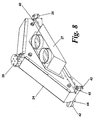
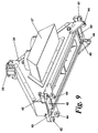
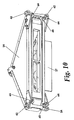
- FIGs 8 - 10 are perspective diagrams of the vacuum delivery carriage shown in Figures 1 - 5 and show an alternative way of providing the two short flexible tubes 26 in communication with the platen assembly 12.
- the vacuum delivery carriage 24 is shown with a single vacuum delivery box 27 on one side of it.
- the single vacuum delivery carriage 27 is arranged for the two short flexible pipes 26 to be connected to it.
- Figures 8 - 10 also show the arrangement of the bearings 40, 42, 44 at the front and the back of the vacuum delivery carriage 24 such that there are three bearing 40, 42, 44 at each corner of the vacuum delivery carriage 24. In total there are twelve bearings 40, 42, 44 which restrain the vacuum delivery carriage 24 to travel along the hollow profile 22.
- the four bearings 42 which rotate about a vertical axis and roll against a side edge of the shoulder 38 inhibit the vacuum delivery carriage 24 from falling off the hollow profile 22 as it travels along the hollow profile 22.
- the four bearings 40 arranged to roll on an upper surface of the shoulder 38 and the four roller bearings 44 arranged to roll on an under surface of the shoulder 38 inhibit the vacuum delivery carriage from rotating about a horizontal axis as it travels along the hollow profile 22.
- a flat bed printer so arranged minimises or at least ameliorates the problems associated with using relatively long and large diameter tubes associate with the prior art to deliver the vacuum to the platen.
- a flat bed printer arranged according to the herein described embodiments eliminates the need for such large diameter and heavy tubing for delivering the vacuum to the platen assembly. Maintenance problems due to the prior art tubes cracking are also eliminated. Accordingly the mass of the flat bed is significantly reduced using the hollow profile 22 and vacuum delivery carriage 24 of the above embodiments. Overall the platen assembly 12 of the herein described embodiments is therefore lighter and the force, and hence motor power required to operate the flat bed printer may be reduced. A smaller motor may be used.
- Embodiments of the invention may provide a quieter printer which consumes less power.
- a further advantage of the above-described embodiments is that the vibrations are reduced when compared to the printer of the prior art which leads to an improved print quality.
Landscapes
- Handling Of Sheets (AREA)
Abstract
Description
- The present invention relates to improvements in or relating to printers.
- Large flat bed printers are used for printing on rigid and semi-rigid substrates. A typical flat bed printer has a print head array arranged to move in one direction and a flat bed arranged to move in a direction perpendicular to the direction of movement of the print head. The flat bed might typically have a dimension of 3.2m X 1.65m and a vacuum is delivered to it to hold the substrate in position during printing. A problem associated with this kind of printer is the need to maintain a constant vacuum over such a large area. The vacuum is required to firmly hold the substrate in position while the flat bed travels a typical distance of 7m with a speed of approximately 2.5m.s-1 and an acceleration of up to 0.8m.s-2.
-
US 5 216 442 discloses an inkjet printer including a movable platen. - In order to provide a firm hold to substrates such as cardboard, Kappa® and vinyl panels a continuous and stable vacuum is typically required of approximately -0.3bar with a flow rate of 450m3.h-1. The vacuum is typically supplied to the flat bed from a vacuum pump using large diameter tubing which is relatively long and which must unfurl as the flat bed travels relative to the vacuum pump. A problem with using such tubing is that it is heavy and significantly increases the flat bed mass. The tubing also causes friction due to the requirement to continuously move the flat bed. A powerful drive must typically be used to operate the flat bed, which is expensive and requires a large amount of energy. Such a powerful drive may also be noisy. The need for the tubing to travel with the flat bed also produces undesirable vibrations which can degrade the print quality. There are also maintenance problems with the large diameter tubing which may crack or split. Overall a lighter bed is more desirable due to the above mentioned problems.
- The invention provides a printer assembly according to appended
claim 1. - The invention also provides a method according to appended claim 11.
- The invention further provides a method of printing according to appended
claim 12. - The invention provides use of a hollow profile and a carriage in a printer to generate a movable aperture for communicating a vacuum from a vacuum source to a platen of the printer.
- The invention provides a carriage which is arranged to move in a first plane and arranged to create a movable aperture in a vacuum communication path.
- The invention provides a hollow profile to provide a vacuum communication path and arranged to create a movable aperture in the vacuum communication path.
- The present invention will be apparent from the following description of preferred embodiments shown by way of example only in the accompanying drawings, of which:-
-
Figure 1 is a perspective diagram of a flat bed printer according to an embodiment of the present invention; -
Figure 2 is a diagram of a vacuum delivery carriage and hollow profile ofFigure 1 shown in section; -
Figure 3 is a diagram of the vacuum delivery carriage and hollow profile ofFigure 2 taken along line A-A; -
Figure 4 is a diagram of the vacuum delivery carriage and hollow profile ofFigure 3 shown in section along line B-B; -
Figure 5 is a perspective diagram of the vacuum delivery carriage and hollow profile shown inFigures 1 - 4 ; -
Figure 6 is a plan view of the printer shown inFigure 1 ; -
Figure 7 is a plan view of the printer shown inFigure 1 with a different printer head arrangement; and -
Figures 8 - 10 are perspective diagrams of the vacuum delivery carriage shown inFigures 1 - 5 according to an alternative embodiment; - Referring to
Figure 1 there is shown a perspective diagram of a flat bed printer according to an embodiment of the present invention, generally designated 10. Theflat bed printer 10 has aplaten assembly 12 with a flatupper surface 14 which is arranged to move in a fore and aft direction indicated byarrow 16. Aprinter head 18 is mounted on aframe 20 and is a fixed printer head which is approximately the same width as theplaten assembly 12. A vacuum pump (not shown inFigure 1 ) to provide a vacuum source is in fluid communication with theplaten assembly 12 to draw air into the upper surface of the platen as discussed below. The air enters theplaten assembly 12 through small holes in the flatupper surface 14 such that media arranged on the flat upper surface are biased towards the platen by air pressure pressing on the media and because of the vacuum. It will be appreciated that the flatupper surface 14 could be any perforated or porous sheet having a low air flow resistance. Once the media is held in place it can be printed upon using theprinter head 18 as required by moving theplaten assembly 12 in the fore andaft direction 16 - The
flat bed printer 10 includes ahollow profile 22 which has aprofile chamber 32 as shown inFigure 3 . Thehollow profile 22 is a beam or bed having avacuum defining chamber 32. Thehollow profile 22 is a way of delivering the vacuum to theplaten assembly 12 and is also support for thevacuum delivery carriage 24. InFigure 1 thehollow profile 22 has avacuum delivery carriage 24 arranged to ride on it. Thevacuum delivery carriage 24 has a carriage chamber 34 (best shown inFigure 3 ) which is in fluid communication with theplaten assembly 12 ofFigure 1 via a pair of shortflexible tubes 26 to deliver the vacuum to the flatupper surface 14 from the vacuum pump as discussed below. Amechanical connection 28 is provided on thevacuum delivery carriage 24 to connect theplaten assembly 12 to thevacuum delivery carriage 24 so that when theplaten assembly 12 is operated in the fore andaft direction 16 thevacuum delivery carriage 24 moves with it. - An overview of the disclosed embodiments is that a vacuum is applied to an inside of a
hollow profile 22 which has a slot along a top edge. A band closes the slot to form a seal and to maintain a vacuum within the hollow profile. A movable carriage lifts the band to create a moving hole where the vacuum exists. The hole moves with theplaten assembly 12 and moves relative to the print head. This allows short vacuum supply tubes to be used to connect the movable carriage to theplaten assembly 12 and avoids the use of long heavy tubes which are required to fold against themselves in a serpentine manner. Overall the disclosed embodiments provide alighter platen assembly 12. - The
carriage chamber 34 of thevacuum delivery carriage 24 is in fluid communication with theprofile chamber 32 of thehollow profile 22. One end of thehollow profile 22 is closed whereas the other end of thehollow profile 22 is in fluid communication with the vacuum pump. In this manner a vacuum path (shown at 33 inFigure 3 ) travels from the vacuum pump, through theprofile chamber 32 of thehollow profile 22, through thecarriage chamber 34 of thevacuum delivery carriage 24, through the shortflexible tubes 26 and to the flatupper surface 14 of theplaten assembly 12. - The
hollow profile 22 is open at a top edge thereof adjacent to where the vacuum delivery carriage 24 rides and delivers the vacuum from theprofile chamber 32 to thecarriage chamber 34. The opening at the top edge of thehollow profile 22 forms an elongate opening in thehollow profile 22. A thin metal orplastic band 30 is also shown inFigure 1 which is arranged to close the elongate opening of thehollow profile 22. The band is threaded through thevacuum delivery carriage 24 as discussed below. Theband 30 is an elongate seal or strip to close the top of thehollow profile 22. -
Figure 2 is a diagram of thevacuum delivery carriage 24 and thehollow profile 22 ofFigure 1 shown in section. Themechanical connection 28 is also shown which causes thevacuum delivery carriage 24 to move with theplaten assembly 12. InFigure 2 thevacuum delivery carriage 24 is shown in situ on thehollow profile 22. -
Figure 3 is a diagram of thevacuum delivery carriage 24 andhollow profile 22 ofFigure 2 taken along line A-A inFigure 2 . InFigure 3 theprofile chamber 32 and thecarriage chamber 34 are shown in fluid communication through agasket 35. The vacuum flow path is also shown at 33 whereby theprofile chamber 32 is shown in fluid communication with thecarriage chamber 34 which is in turn in fluid communication with the shortflexible tubes 26 to deliver the vacuum to theplaten assembly 12. Theband 30 is also shown supported by arigid net 36. Therigid net 36 rests onshoulders 38 of thehollow profile 22 and inhibits theband 30 from buckling due to atmospheric pressure when the vacuum is applied. In use, the vacuum causes atmospheric pressure to clamp theband 30 to thehollow profile 22 which further reduces leaks. -
Figure 3 shows threebearings vacuum delivery carriage 24 as seen inFigure 3 . Thefirst bearing 40 is arranged to roll on an upper surface of theshoulder 38 and to rotate about a horizontal axis. Thesecond bearing 42 is arranged to roll on a side edge of theshoulder 38 and to rotate about a vertical axis. Thethird bearing 44 is arranged to roll on an under surface of theshoulder 38 and to rotate about a horizontal axis. The threebearings vacuum delivery carriage 24 are mirrored bysimilar bearings vacuum delivery carriage 24.Figure 3 showsbearings vacuum delivery carriage 24, but it will be described below with reference toFigures 8 - 10 thatsimilar bearings vacuum delivery carriage 24. Thebearings vacuum delivery carriage 24 to ride on thehollow profile 22 and inhibit thevacuum delivery carriage 24 from rotating relative to thehollow profile 22 when it is moved along thehollow profile 22 by theplaten assembly 12. Agasket 35 is also provided between thevacuum delivery carriage 24 and thehollow profile 22 to seal thevacuum delivery carriage 24 to thehollow profile 22 as it travels along thehollow profile 22. Thebearings gasket 35 to provide relatively free and smooth movement of thevacuum delivery carriage 24 whilst also inhibiting air leaking into theprofile chamber 32 and thecarriage chamber 34. Thegasket 35 is made of a low friction material such as polypropylene to allow it to slide along theshoulder 38 of thehollow profile 22 with minimal wear. -
Figure 3 further shows anupper band roller 46 which is arranged to allow theband 30 to pass over it. Thisupper band roller 46 is described in greater detail with reference toFigure 4 . -
Figure 4 is a diagram of thevacuum delivery carriage 24 and thehollow profile 22 ofFigure 3 shown in section along line B-B.Figure 4 shows theupper band roller 46 and twolower band rollers vacuum delivery carriage 24. Theband 30 is threaded around theband rollers lower band rollers upper band roller 46. Thelower band rollers band 30 to thehollow profile 22 whereas theupper band roller 46 lifts theband 30 to provide a movable opening ormovable aperture 52 in thehollow profile 22. Themovable opening 52 is such that as thevacuum delivery carriage 24 travels back and forth themovable opening 52 travels with it because theupper band roller 46 lifts theband 30. It will be appreciated that theupper band roller 46 lifts theband 30 into thecarriage chamber 34 and aside opening 54 in a wall of thevacuum delivery carriage 24 provides thecarriage chamber 34 in fluid communication with the shortflexible tubes 26 to deliver the vacuum to theplaten assembly 12. -
Figure 5 is a perspective diagram of thevacuum delivery carriage 24 andhollow profile 22 shown inFigures 1 - 4 . InFigure 5 the shortflexible tubes 26 are shown at either end of thevacuum delivery carriage 24 for provide thecarriage chamber 34 and theplaten assembly 12 in fluid communication with one another. Each shortflexible tube 26 is shown in fluid communication with a respectivevacuum delivery box 27 on either side of thevacuum delivery carriage 24. Eachvacuum delivery box 27 is in fluid communication with thecarriage chamber 34. Theband 30 is also shown on top of thehollow profile 22 and can be seen passing underneath one of thelower band rollers 48. -
Figure 6 is a plan view of theprinter 10 shown inFigure 1 and shows theplaten assembly 12 which is operable to move in a fore andaft direction 16. Theframe 20 is also shown having the fixedprinter head 18 mounted on it. Thehollow profile 22 is also shown which has thevacuum delivery carriage 24 arranged to move thereon. It will be appreciated that thehollow profile 22 and theframe 20 are stationary whilst theplaten assembly 22 and thevacuum delivery carriage 24 move together in the fore andaft direction 16. Themovable opening 52 is also shown between thevacuum delivery carriage 24 and thehollow profile 22. It will also be appreciated that themovable opening 52 moves with thevacuum delivery carriage 24 and theplaten assembly 12 in the fore andaft direction 16. -
Figure 7 is a plan view of the printer shown inFigure 1 with a different printer head arrangement. InFigure 7 theprinter head 18 is arranged to move on theframe 20 in atransverse direction 23 which is perpendicular to the fore andaft direction 16. -
Figures 8 - 10 are perspective diagrams of the vacuum delivery carriage shown inFigures 1 - 5 and show an alternative way of providing the two shortflexible tubes 26 in communication with theplaten assembly 12. InFigures 8 - 10 thevacuum delivery carriage 24 is shown with a singlevacuum delivery box 27 on one side of it. The singlevacuum delivery carriage 27 is arranged for the two shortflexible pipes 26 to be connected to it. -
Figures 8 - 10 also show the arrangement of thebearings vacuum delivery carriage 24 such that there are three bearing 40, 42, 44 at each corner of thevacuum delivery carriage 24. In total there are twelvebearings vacuum delivery carriage 24 to travel along thehollow profile 22. In use the fourbearings 42 which rotate about a vertical axis and roll against a side edge of theshoulder 38 inhibit thevacuum delivery carriage 24 from falling off thehollow profile 22 as it travels along thehollow profile 22. In use the fourbearings 40 arranged to roll on an upper surface of theshoulder 38 and the fourroller bearings 44 arranged to roll on an under surface of theshoulder 38 inhibit the vacuum delivery carriage from rotating about a horizontal axis as it travels along thehollow profile 22. - A flat bed printer so arranged minimises or at least ameliorates the problems associated with using relatively long and large diameter tubes associate with the prior art to deliver the vacuum to the platen. A flat bed printer arranged according to the herein described embodiments eliminates the need for such large diameter and heavy tubing for delivering the vacuum to the platen assembly. Maintenance problems due to the prior art tubes cracking are also eliminated. Accordingly the mass of the flat bed is significantly reduced using the
hollow profile 22 andvacuum delivery carriage 24 of the above embodiments. Overall theplaten assembly 12 of the herein described embodiments is therefore lighter and the force, and hence motor power required to operate the flat bed printer may be reduced. A smaller motor may be used. Embodiments of the invention may provide a quieter printer which consumes less power. A further advantage of the above-described embodiments is that the vibrations are reduced when compared to the printer of the prior art which leads to an improved print quality. - It will be appreciated by persons skilled in the art that the present invention is not limited to what as been particularly shown and described above. Rather, the scope of the present invention is defined by the claims that follow.
Claims (12)
- A print assembly adapted for use with a print head (18) comprising:a platen (12) operable to move in a first plane in a fore and aft direction (16);a vacuum source in fluid communication with the platen (12) to provide a vacuum communication path (33) to draw air through the platen (12) such that a sheet of media arranged on the platen (12) is biased towards it; andan aperture (52) in the vacuum communication path (33) between the vacuum source and the platen (12),characterized in thatthe aperture (52) is arranged to move with the platen (12) in the fore and aft direction (16),the movable aperture (52) is provided by a hollow profile (22) and a carriage (24) which is movable on the hollow profile (22),the carriage (24) is movable with the platen (12) and arranged to create the movable aperture (52) as it moves on the hollow profile (22), andthe hollow profile (22) has an elongate opening having a band (30) to close it at least partially, the carriage (24) operable to separate the band (30) from the hollow profile (22) to provide the movable aperture (52).
- A printer assembly according to claim 1 wherein the platen (12) comprises an upper surface (14) and a plurality of holes in the upper surface (14), and wherein the vacuum communication path (33) is between the vacuum source and the holes in the upper surface (14) of the platen (12).
- A printer assembly according to claim 1 and further including a gasket between the carriage (24) and the hollow profile (22).
- A printer assembly according to claim 1 wherein the carriage (24) is provided with at least one bearing to reduce friction when the carriage (24) moves on the hollow profile (22).
- A printer assembly according to claim 4 wherein at least one bearing constrains the carriage (24) in a lateral direction relative to the hollow profile (22), or from rotating relative to the hollow profile (22).
- A printer assembly according to claim 1 wherein the carriage (24) is further provided with at least one band roller (46, 48, 50) which contacts the band (30).
- A printer assembly according to claim 6 wherein at least one band roller (48) is arranged to separate the band (30) from the hollow profile (22) to provide the movable aperture (52).
- A printer assembly according to claim 6 wherein at least one band roller (46, 50) is arranged to urge the band (30) against the hollow profile (22).
- A printer assembly according to claim 1 and further including a print head (18) adapted to move in a transverse direction relative to the platen (12).
- A printer assembly according to claim 1 and further including a fixed print head (18) substantially the same length as the width of the platen (12).
- A method of supporting and holding media to be printed upon using a printer assembly according to one of claims 1 to 10, the method comprising:applying a vacuum to create the vacuum communication path (33) to draw air through the platen (12) such that a sheet of media arranged on the platen (12) is biased towards it; andmoving the platen (12) in a fore and aft direction (116) to generate the moveable aperture (52) in the vacuum communication path (33) between the vacuum source and the platen (12).
- A method of printing using a printer having a platen (12) which is operable to move in a first plane, the method comprising:supporting and holding media to be printed upon in accordance with claim 11; andprinting on the media whilst it is held in position on the platen (12) by the vacuum.
Applications Claiming Priority (1)
| Application Number | Priority Date | Filing Date | Title |
|---|---|---|---|
| PCT/US2007/068118 WO2008136823A1 (en) | 2007-05-03 | 2007-05-03 | Improvements in or relating to printers |
Publications (2)
| Publication Number | Publication Date |
|---|---|
| EP2142377A1 EP2142377A1 (en) | 2010-01-13 |
| EP2142377B1 true EP2142377B1 (en) | 2012-06-13 |
Family
ID=38626735
Family Applications (1)
| Application Number | Title | Priority Date | Filing Date |
|---|---|---|---|
| EP07761804A Not-in-force EP2142377B1 (en) | 2007-05-03 | 2007-05-03 | Improvements in or relating to printers |
Country Status (4)
| Country | Link |
|---|---|
| US (1) | US8740487B2 (en) |
| EP (1) | EP2142377B1 (en) |
| CN (1) | CN101668644B (en) |
| WO (1) | WO2008136823A1 (en) |
Families Citing this family (4)
| Publication number | Priority date | Publication date | Assignee | Title |
|---|---|---|---|---|
| DE102012103533A1 (en) * | 2012-04-20 | 2013-10-24 | Köra-Packmat Maschinenbau GmbH | Device for conveying a substrate and system for printing on a substrate |
| ES2548352B1 (en) * | 2014-03-14 | 2016-07-13 | Jesus Francisco Barberan Latorre | VACUUM SYSTEM FOR HOLDING PARTS IN PRINTING MACHINES |
| WO2017028900A1 (en) | 2015-08-17 | 2017-02-23 | Hewlett-Packard Development Company, L.P. | Media holddown suction force adjustment |
| DE102020115258B3 (en) * | 2020-06-09 | 2021-09-16 | Karl Storz Se & Co. Kg | Endoscope with swiveling image capturing device |
Family Cites Families (6)
| Publication number | Priority date | Publication date | Assignee | Title |
|---|---|---|---|---|
| US5216442A (en) * | 1991-11-14 | 1993-06-01 | Xerox Corporation | Moving platen architecture for an ink jet printer |
| US5287127A (en) * | 1992-02-25 | 1994-02-15 | Salmon Peter C | Electrostatic printing apparatus and method |
| IT1267490B1 (en) * | 1994-11-09 | 1997-02-05 | Sapim Amada Spa | DEVICE FOR GRIPPING AND HANDLING OF PIECES OF MATERIAL IN SHEET AND MANIPULATOR OF PIECES OF MATERIAL IN SHEET INCLUDING THIS |
| US6109745A (en) * | 1998-07-17 | 2000-08-29 | Eastman Kodak Company | Borderless ink jet printing on receivers |
| US6543948B2 (en) | 2001-02-09 | 2003-04-08 | Hewlett-Packard Company | Printer with vacuum platen having selectable active area |
| CN1193892C (en) * | 2001-10-17 | 2005-03-23 | 精工爱普生株式会社 | Fixed material conveying device, discharge device, discharge method, and solid-liquid device |
-
2007
- 2007-05-03 EP EP07761804A patent/EP2142377B1/en not_active Not-in-force
- 2007-05-03 US US12/596,393 patent/US8740487B2/en active Active
- 2007-05-03 CN CN2007800528275A patent/CN101668644B/en not_active Expired - Fee Related
- 2007-05-03 WO PCT/US2007/068118 patent/WO2008136823A1/en not_active Ceased
Also Published As
| Publication number | Publication date |
|---|---|
| WO2008136823A1 (en) | 2008-11-13 |
| US20100186613A1 (en) | 2010-07-29 |
| EP2142377A1 (en) | 2010-01-13 |
| US8740487B2 (en) | 2014-06-03 |
| CN101668644B (en) | 2011-09-14 |
| CN101668644A (en) | 2010-03-10 |
Similar Documents
| Publication | Publication Date | Title |
|---|---|---|
| US6517179B2 (en) | Inkjet printing apparatus | |
| CN102177027B (en) | Machine base for printer and inkjet printer using the same | |
| US8740487B2 (en) | Printers | |
| US20020047885A1 (en) | Recording apparatus | |
| JP2009280320A (en) | Conveying device, recording apparatus equipped with conveying device and conveying method for recording medium | |
| JP3068519B2 (en) | Pneumatic sheet guide device installed in printing press | |
| US20190016160A1 (en) | Inkjet recording device | |
| EP3251989B1 (en) | Web winding with friction-based tensioning | |
| US8292420B2 (en) | Locating device for an inkjet printer | |
| JP2006103327A (en) | Sheet handling apparatus | |
| JPWO2017203972A1 (en) | Recording medium conveyance device and inkjet recording device | |
| US11034172B2 (en) | Feeding a print medium and printer | |
| JP6080677B2 (en) | Cutting device and cutting method | |
| US8534669B2 (en) | Conveyance device and image forming device | |
| EP3126061B1 (en) | Fluid application | |
| JP2020121853A (en) | Printer | |
| JP5931471B2 (en) | Recording device | |
| US20220297441A1 (en) | Printing device and back pressure control method | |
| JP2005169788A (en) | Image forming apparatus | |
| EP3427961B1 (en) | Method of ink jet printing on porous media | |
| JP2008254222A (en) | Gap adjusting device, recording device, liquid ejecting device | |
| EP0876913B1 (en) | Ink-jet image forming device | |
| US20250332850A1 (en) | Recording apparatus | |
| EP2990364B1 (en) | Print substrate transport assembly | |
| US20230150283A1 (en) | Recording device |
Legal Events
| Date | Code | Title | Description |
|---|---|---|---|
| PUAI | Public reference made under article 153(3) epc to a published international application that has entered the european phase |
Free format text: ORIGINAL CODE: 0009012 |
|
| 17P | Request for examination filed |
Effective date: 20091029 |
|
| AK | Designated contracting states |
Kind code of ref document: A1 Designated state(s): AT BE BG CH CY CZ DE DK EE ES FI FR GB GR HU IE IS IT LI LT LU LV MC MT NL PL PT RO SE SI SK TR |
|
| DAX | Request for extension of the european patent (deleted) | ||
| 17Q | First examination report despatched |
Effective date: 20101202 |
|
| GRAP | Despatch of communication of intention to grant a patent |
Free format text: ORIGINAL CODE: EPIDOSNIGR1 |
|
| GRAS | Grant fee paid |
Free format text: ORIGINAL CODE: EPIDOSNIGR3 |
|
| GRAA | (expected) grant |
Free format text: ORIGINAL CODE: 0009210 |
|
| AK | Designated contracting states |
Kind code of ref document: B1 Designated state(s): AT BE BG CH CY CZ DE DK EE ES FI FR GB GR HU IE IS IT LI LT LU LV MC MT NL PL PT RO SE SI SK TR |
|
| REG | Reference to a national code |
Ref country code: GB Ref legal event code: FG4D |
|
| REG | Reference to a national code |
Ref country code: AT Ref legal event code: REF Ref document number: 561810 Country of ref document: AT Kind code of ref document: T Effective date: 20120615 Ref country code: CH Ref legal event code: EP |
|
| REG | Reference to a national code |
Ref country code: IE Ref legal event code: FG4D |
|
| REG | Reference to a national code |
Ref country code: DE Ref legal event code: R096 Ref document number: 602007023379 Country of ref document: DE Effective date: 20120809 |
|
| REG | Reference to a national code |
Ref country code: NL Ref legal event code: VDEP Effective date: 20120613 |
|
| PG25 | Lapsed in a contracting state [announced via postgrant information from national office to epo] |
Ref country code: FI Free format text: LAPSE BECAUSE OF FAILURE TO SUBMIT A TRANSLATION OF THE DESCRIPTION OR TO PAY THE FEE WITHIN THE PRESCRIBED TIME-LIMIT Effective date: 20120613 Ref country code: LT Free format text: LAPSE BECAUSE OF FAILURE TO SUBMIT A TRANSLATION OF THE DESCRIPTION OR TO PAY THE FEE WITHIN THE PRESCRIBED TIME-LIMIT Effective date: 20120613 Ref country code: SE Free format text: LAPSE BECAUSE OF FAILURE TO SUBMIT A TRANSLATION OF THE DESCRIPTION OR TO PAY THE FEE WITHIN THE PRESCRIBED TIME-LIMIT Effective date: 20120613 Ref country code: CY Free format text: LAPSE BECAUSE OF FAILURE TO SUBMIT A TRANSLATION OF THE DESCRIPTION OR TO PAY THE FEE WITHIN THE PRESCRIBED TIME-LIMIT Effective date: 20120613 |
|
| REG | Reference to a national code |
Ref country code: AT Ref legal event code: MK05 Ref document number: 561810 Country of ref document: AT Kind code of ref document: T Effective date: 20120613 |
|
| REG | Reference to a national code |
Ref country code: LT Ref legal event code: MG4D Effective date: 20120613 |
|
| PG25 | Lapsed in a contracting state [announced via postgrant information from national office to epo] |
Ref country code: SI Free format text: LAPSE BECAUSE OF FAILURE TO SUBMIT A TRANSLATION OF THE DESCRIPTION OR TO PAY THE FEE WITHIN THE PRESCRIBED TIME-LIMIT Effective date: 20120613 Ref country code: LV Free format text: LAPSE BECAUSE OF FAILURE TO SUBMIT A TRANSLATION OF THE DESCRIPTION OR TO PAY THE FEE WITHIN THE PRESCRIBED TIME-LIMIT Effective date: 20120613 |
|
| PG25 | Lapsed in a contracting state [announced via postgrant information from national office to epo] |
Ref country code: EE Free format text: LAPSE BECAUSE OF FAILURE TO SUBMIT A TRANSLATION OF THE DESCRIPTION OR TO PAY THE FEE WITHIN THE PRESCRIBED TIME-LIMIT Effective date: 20120613 Ref country code: IS Free format text: LAPSE BECAUSE OF FAILURE TO SUBMIT A TRANSLATION OF THE DESCRIPTION OR TO PAY THE FEE WITHIN THE PRESCRIBED TIME-LIMIT Effective date: 20121013 Ref country code: BE Free format text: LAPSE BECAUSE OF FAILURE TO SUBMIT A TRANSLATION OF THE DESCRIPTION OR TO PAY THE FEE WITHIN THE PRESCRIBED TIME-LIMIT Effective date: 20120613 Ref country code: AT Free format text: LAPSE BECAUSE OF FAILURE TO SUBMIT A TRANSLATION OF THE DESCRIPTION OR TO PAY THE FEE WITHIN THE PRESCRIBED TIME-LIMIT Effective date: 20120613 Ref country code: RO Free format text: LAPSE BECAUSE OF FAILURE TO SUBMIT A TRANSLATION OF THE DESCRIPTION OR TO PAY THE FEE WITHIN THE PRESCRIBED TIME-LIMIT Effective date: 20120613 Ref country code: SK Free format text: LAPSE BECAUSE OF FAILURE TO SUBMIT A TRANSLATION OF THE DESCRIPTION OR TO PAY THE FEE WITHIN THE PRESCRIBED TIME-LIMIT Effective date: 20120613 Ref country code: CZ Free format text: LAPSE BECAUSE OF FAILURE TO SUBMIT A TRANSLATION OF THE DESCRIPTION OR TO PAY THE FEE WITHIN THE PRESCRIBED TIME-LIMIT Effective date: 20120613 |
|
| PG25 | Lapsed in a contracting state [announced via postgrant information from national office to epo] |
Ref country code: PT Free format text: LAPSE BECAUSE OF FAILURE TO SUBMIT A TRANSLATION OF THE DESCRIPTION OR TO PAY THE FEE WITHIN THE PRESCRIBED TIME-LIMIT Effective date: 20121015 Ref country code: IT Free format text: LAPSE BECAUSE OF FAILURE TO SUBMIT A TRANSLATION OF THE DESCRIPTION OR TO PAY THE FEE WITHIN THE PRESCRIBED TIME-LIMIT Effective date: 20120613 Ref country code: PL Free format text: LAPSE BECAUSE OF FAILURE TO SUBMIT A TRANSLATION OF THE DESCRIPTION OR TO PAY THE FEE WITHIN THE PRESCRIBED TIME-LIMIT Effective date: 20120613 |
|
| PG25 | Lapsed in a contracting state [announced via postgrant information from national office to epo] |
Ref country code: NL Free format text: LAPSE BECAUSE OF FAILURE TO SUBMIT A TRANSLATION OF THE DESCRIPTION OR TO PAY THE FEE WITHIN THE PRESCRIBED TIME-LIMIT Effective date: 20120613 |
|
| PLBE | No opposition filed within time limit |
Free format text: ORIGINAL CODE: 0009261 |
|
| STAA | Information on the status of an ep patent application or granted ep patent |
Free format text: STATUS: NO OPPOSITION FILED WITHIN TIME LIMIT |
|
| PG25 | Lapsed in a contracting state [announced via postgrant information from national office to epo] |
Ref country code: DK Free format text: LAPSE BECAUSE OF FAILURE TO SUBMIT A TRANSLATION OF THE DESCRIPTION OR TO PAY THE FEE WITHIN THE PRESCRIBED TIME-LIMIT Effective date: 20120613 Ref country code: ES Free format text: LAPSE BECAUSE OF FAILURE TO SUBMIT A TRANSLATION OF THE DESCRIPTION OR TO PAY THE FEE WITHIN THE PRESCRIBED TIME-LIMIT Effective date: 20120924 |
|
| 26N | No opposition filed |
Effective date: 20130314 |
|
| REG | Reference to a national code |
Ref country code: DE Ref legal event code: R097 Ref document number: 602007023379 Country of ref document: DE Effective date: 20130314 |
|
| PG25 | Lapsed in a contracting state [announced via postgrant information from national office to epo] |
Ref country code: BG Free format text: LAPSE BECAUSE OF FAILURE TO SUBMIT A TRANSLATION OF THE DESCRIPTION OR TO PAY THE FEE WITHIN THE PRESCRIBED TIME-LIMIT Effective date: 20120913 |
|
| PG25 | Lapsed in a contracting state [announced via postgrant information from national office to epo] |
Ref country code: MC Free format text: LAPSE BECAUSE OF FAILURE TO SUBMIT A TRANSLATION OF THE DESCRIPTION OR TO PAY THE FEE WITHIN THE PRESCRIBED TIME-LIMIT Effective date: 20120613 |
|
| REG | Reference to a national code |
Ref country code: CH Ref legal event code: PL |
|
| PG25 | Lapsed in a contracting state [announced via postgrant information from national office to epo] |
Ref country code: LI Free format text: LAPSE BECAUSE OF NON-PAYMENT OF DUE FEES Effective date: 20130531 Ref country code: CH Free format text: LAPSE BECAUSE OF NON-PAYMENT OF DUE FEES Effective date: 20130531 |
|
| REG | Reference to a national code |
Ref country code: IE Ref legal event code: MM4A |
|
| PG25 | Lapsed in a contracting state [announced via postgrant information from national office to epo] |
Ref country code: IE Free format text: LAPSE BECAUSE OF NON-PAYMENT OF DUE FEES Effective date: 20130503 |
|
| PG25 | Lapsed in a contracting state [announced via postgrant information from national office to epo] |
Ref country code: MT Free format text: LAPSE BECAUSE OF FAILURE TO SUBMIT A TRANSLATION OF THE DESCRIPTION OR TO PAY THE FEE WITHIN THE PRESCRIBED TIME-LIMIT Effective date: 20120613 |
|
| PG25 | Lapsed in a contracting state [announced via postgrant information from national office to epo] |
Ref country code: TR Free format text: LAPSE BECAUSE OF FAILURE TO SUBMIT A TRANSLATION OF THE DESCRIPTION OR TO PAY THE FEE WITHIN THE PRESCRIBED TIME-LIMIT Effective date: 20120613 |
|
| PG25 | Lapsed in a contracting state [announced via postgrant information from national office to epo] |
Ref country code: LU Free format text: LAPSE BECAUSE OF NON-PAYMENT OF DUE FEES Effective date: 20130503 Ref country code: HU Free format text: LAPSE BECAUSE OF FAILURE TO SUBMIT A TRANSLATION OF THE DESCRIPTION OR TO PAY THE FEE WITHIN THE PRESCRIBED TIME-LIMIT; INVALID AB INITIO Effective date: 20070503 |
|
| PG25 | Lapsed in a contracting state [announced via postgrant information from national office to epo] |
Ref country code: GR Free format text: LAPSE BECAUSE OF NON-PAYMENT OF DUE FEES Effective date: 20120613 |
|
| REG | Reference to a national code |
Ref country code: FR Ref legal event code: PLFP Year of fee payment: 10 |
|
| REG | Reference to a national code |
Ref country code: FR Ref legal event code: PLFP Year of fee payment: 11 |
|
| REG | Reference to a national code |
Ref country code: FR Ref legal event code: PLFP Year of fee payment: 12 |
|
| PGFP | Annual fee paid to national office [announced via postgrant information from national office to epo] |
Ref country code: FR Payment date: 20210608 Year of fee payment: 16 |
|
| PGFP | Annual fee paid to national office [announced via postgrant information from national office to epo] |
Ref country code: GB Payment date: 20220426 Year of fee payment: 16 Ref country code: DE Payment date: 20210716 Year of fee payment: 16 |
|
| REG | Reference to a national code |
Ref country code: DE Ref legal event code: R119 Ref document number: 602007023379 Country of ref document: DE |
|
| GBPC | Gb: european patent ceased through non-payment of renewal fee |
Effective date: 20230503 |
|
| PG25 | Lapsed in a contracting state [announced via postgrant information from national office to epo] |
Ref country code: DE Free format text: LAPSE BECAUSE OF NON-PAYMENT OF DUE FEES Effective date: 20231201 Ref country code: GB Free format text: LAPSE BECAUSE OF NON-PAYMENT OF DUE FEES Effective date: 20230503 |
|
| PG25 | Lapsed in a contracting state [announced via postgrant information from national office to epo] |
Ref country code: FR Free format text: LAPSE BECAUSE OF NON-PAYMENT OF DUE FEES Effective date: 20230531 |