EP2142301B1 - Control method for a crusher and a crusher - Google Patents
Control method for a crusher and a crusher Download PDFInfo
- Publication number
- EP2142301B1 EP2142301B1 EP07730680.1A EP07730680A EP2142301B1 EP 2142301 B1 EP2142301 B1 EP 2142301B1 EP 07730680 A EP07730680 A EP 07730680A EP 2142301 B1 EP2142301 B1 EP 2142301B1
- Authority
- EP
- European Patent Office
- Prior art keywords
- crusher
- crushing
- actuator
- cycle frequency
- frequency
- Prior art date
- Legal status (The legal status is an assumption and is not a legal conclusion. Google has not performed a legal analysis and makes no representation as to the accuracy of the status listed.)
- Active
Links
Images


Classifications
-
- B—PERFORMING OPERATIONS; TRANSPORTING
- B02—CRUSHING, PULVERISING, OR DISINTEGRATING; PREPARATORY TREATMENT OF GRAIN FOR MILLING
- B02C—CRUSHING, PULVERISING, OR DISINTEGRATING IN GENERAL; MILLING GRAIN
- B02C2/00—Crushing or disintegrating by gyratory or cone crushers
- B02C2/02—Crushing or disintegrating by gyratory or cone crushers eccentrically moved
- B02C2/04—Crushing or disintegrating by gyratory or cone crushers eccentrically moved with vertical axis
- B02C2/047—Crushing or disintegrating by gyratory or cone crushers eccentrically moved with vertical axis and with head adjusting or controlling mechanisms
-
- B—PERFORMING OPERATIONS; TRANSPORTING
- B02—CRUSHING, PULVERISING, OR DISINTEGRATING; PREPARATORY TREATMENT OF GRAIN FOR MILLING
- B02C—CRUSHING, PULVERISING, OR DISINTEGRATING IN GENERAL; MILLING GRAIN
- B02C25/00—Control arrangements specially adapted for crushing or disintegrating
Definitions
- the invention relates to a method according to the preamble of the appended claim 1.
- the invention also relates to a crusher according to the preamble of claim 7.
- the invention relates to crushers and preferably cone and gyratory crushers, but the arrangement can also be used in other crushers, such as impact and jaw crushers.
- cone and gyratory crushers are used for intermediate and fine crushing of material, such as rock.
- Cone crushers comprise a vertical eccentric shaft and an oblique inner hole fitted therein. A main shaft, to which a supporting cone is often fastened, is fitted in the hole. The supporting cone is surrounded by the frame of the crusher, to which has been mounted a means called an outer crushing blade and functioning as a wearing part. To the supporting cone, in turn, has been mounted a means called an inner crushing blade and used as a wearing part.
- the inner crushing blade and the outer crushing blade together form a crushing chamber, in which the feed material is crushed.
- the eccentric shaft is rotated, the main shaft and thereby the supporting cone are entrained in an oscillating motion, wherein the gap between the inner and outer crushing blades varies at each point during the cycle.
- the smallest gap occurring during the cycle is called the setting of the crusher, and the difference between the maximum and the minimum of the gap is called the stroke of the crusher.
- the main shaft of a typical cone crusher is bearing-mounted below the crushing cone only.
- the main shaft of the crusher is further supported at its upper end to the frame by means of an upper thrust bearing. It is this subtype of a cone crusher that is normally called a gyratory crusher.
- the operation of the crusher must be adjusted, as the quality and quantity of the material to be crushed vary.
- the operation is adjusted by controlling the settings of the blades of the crusher.
- the settings are adjusted on the basis of the power consumption (input power) and/or the crushing force.
- such an adjustment of the crusher is difficult or is not necessarily possible at all in crushers in which long strokes are used.
- the gyratory crusher can normally be adjusted by means of a hydraulic system in such a way that the main shaft can be moved in the vertical direction with respect to the frame of the crusher. This makes it possible to change the setting of the crusher in such a way that the grain size of the crushed material corresponds to the grain size desired at each time, and/or to keep the setting constant as the crushing blades are worn.
- the adjustment may also be made by lifting and lowering the upper frame of the crusher and the crushing blade mounted on it, in relation to the lower frame of the crusher and the main shaft which is stationary with respect to the lower frame in the vertical direction.
- Publication WO 2005 007293 A1 discloses a method for controlling a crusher.
- the setting of the crusher is adjusted in order to optimize the crushing process on the basis of measurement of the crushing force such that maximum available load is used when the material to be crushed is processed in the crusher.
- the rotation speed of the crusher driving device can be adjusted in order to control the load of the crusher.
- the method according to the invention is primarily characterized in what will be presented in the characterizing part of the independent claim 1.
- the crusher according to the invention is primarily characterized in what will be presented in the characterizing part of the independent claim 7.
- the other, dependent claims will present some preferred embodiments of the invention.
- cone crusher will be used to refer to all crushers, in which material is crushed by means of a cone, irrespective of the method of supporting the cone and its shaft.
- a cone crusher will be used as an example crusher, but the solution to be presented can also be applied in other crushers, such as impact crushers and jaw crushers.
- the crushing of the material is effected by another crushing means than a crushing cone.
- the arrangements relating to the crushing cone can also be applied in other movable crushing means.
- the idea is to control the speed, or frequency, of the cycle of the crushing means in the crusher, for example the crushing cone, on the basis of the power input in the actuator moving the crushing cone, and/or the crushing force of the crusher.
- the idea is to control the cycle frequency of the crushing means of the crusher on the basis of the particle distribution in the crushed material produced by the crusher, or to control the cycle frequency of the crushing means of the crusher on the basis of the quantity of the crushed material produced by the crusher.
- the crusher comprises at least a frame, a crushing means and an actuator for moving the crushing means. Furthermore, the crusher comprises measuring devices for measuring the power input in the actuator and/or the crushing force. The crusher also comprises a control unit for processing measurement data and for generating control data. The control data is used for controlling an adjusting device for adjusting the cycle frequency of the crushing means.
- the power input in the actuator and/or the crushing force are determined, and this data is used for controlling the cycle frequency of the crushing means.
- the cycle frequency is adjusted by controlling the rotation speed of the actuator.
- cycle frequency for the crushing means of the crusher, at which maximum productivity and utilization degree can be achieved with the power available.
- This cycle frequency depends, among other things, on the quality and the input rate of the material to be crushed.
- the cycle frequency is also affected by the grain size aimed at, as well as the settings of the crusher.
- the aim is to determine the lowest cycle frequency of the crushing means possible with the power input of the crusher, in order to achieve a maximum production of crushed material.
- the power input in the actuator and/or the crushing force is determined continuously, and the cycle frequency of the crushing means is controlled continuously.
- the frequency of the crusher is adjusted to adjust the particle size distribution of the crushed material.
- the particle size distribution of the crushed material is adjusted as desired by operating the crusher at various frequencies.
- the cycle frequency of the crushing means is adjusted by a frequency converter affecting the rotation speed of the actuator.
- the arrangement of adjusting the frequency is substantially not dependent of the stroke of the crusher.
- the adjusting arrangement according to the invention can be applied in various crushers, such as, for example, crushers with long and short strokes.
- the solution of adjusting the frequency of the crushing means can also be combined with other control arrangements, such as the adjustment of the settings.
- the cycle frequency of the crushing means is changed, if necessary, to correspond to the changed settings.
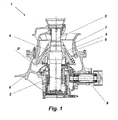
- a cone crusher unit 1 shown in Fig. 1 comprises a vertical eccentric shaft 2 and an oblique inner hole fitted therein.
- a main shaft 3 is fitted in the hole inside the eccentric shaft 2, and a supporting cone 4 is often mounted on the main shaft 3.
- a means called an inner crushing blade 5 and used as a wearing part has been mounted to the supporting cone 4.
- the supporting cone 4 is surrounded by the frame 6 of the crusher, on which has, in turn, been mounted a means called an outer crushing blade 7 and functioning as a wearing part.
- the inner and outer crushing blades 5, 7 together form a crushing chamber 8, in which the feed material is crushed.
- the main shaft 3 and thereby the supporting cone 4 are entrained in an oscillating motion, wherein the gap between the inner crushing blade 5 and the outer crushing blade 7 varies at each point during the cycle.
- the smallest gap occurring during the cycle is called the setting S of the crusher, and the difference between the maximum and the minimum of the gap is called the stroke of the crusher.
- cycle frequency is used to define how fast the gap between the inner crushing blade 5 and the outer crushing blade 7 varies at each point. For example, when the frequency is 60, the inner crushing blade 5 moves 60 times per second between the extreme positions of its path; in other words, there are 3600 cycles per minute.
- Figure 2 shows an actuator 10, such as an electric motor, which produces the motion energy required by the crushing unit 1.
- the movement of the actuator 10 is transmitted by a drive shaft 9 to the eccentric shaft 2.
- the actuator 10 receives input from an adjusting device 11 which can be used to affect the rotation speed of the actuator.
- the adjusting device 11 is a frequency converter which is used to influence the frequency of the alternating current to be supplied to the actuator 10 and thereby the rotation speed of the electric motor.
- Figure 2 also shows, in principle, a first measuring device 12 for measuring the power input in the actuator 10, as well as a second measuring device 13 for measuring the crushing force.
- the measuring devices 12, 13 can be implemented in a variety of ways. For example, if the actuator 10 is an electric motor, power measurement or current measurement can be utilized for measuring the electric power input in it. Also, the placement of the measuring devices 12, 13 is dependent on the application. For example, the power of the actuator 10 can be measured before or after the control unit 11. In one embodiment, the power measurement 12 is arranged in connection with the control unit 11.
- the crushing force can be determined and measured in a variety of ways and at different locations, depending on the application.
- the crushing force can be determined by means of devices used for adjusting the setting.
- the crushing force of a gyratory crusher can be determined by measuring the pressure of the control cylinder.
- a cone crusher can be provided with a cylinder whose pressure is proportional to the crushing force.
- the crushing force can also be measured by measuring the stress.
- pressure measuring devices or stress measuring devices can be used as the measuring devices 13.
- the measuring devices 12, 13 consist of several measurement sensors which possibly measure different variables.
- the data from these measurement sensors is used for generating the data indicating the power input in the actuator 10 and/or the crushing force.
- Figure 2 also shows a control unit 14, to which the data from the first measuring device 12 and/or the second measuring device 13 is transferred.
- the control unit 14 processes measurement data from the first measuring device 12 and/or the second measuring device 13, preferably by software. On the basis of the data, the control unit 14 generates control data for controlling the adjusting device 11.
- the adjusting device 11 controls the speed of the actuator 10, such as the rotation speed of the electric motor.
- the motion generated by the actuator 10 is transmitted by the drive shaft 9, the eccentric shaft 2 and the main shaft 3 to the supporting cone 4, wherein the cycle frequency of the supporting cone 4 and the crushing blades 5 changes when the speed of the actuator is changed.
- the power input in the actuator 10 and/or the crushing force are determined continuously, and the rotation speed of the actuator 10 and thereby also the cycle frequency of the crushing cone 4 and the inner crushing blades 5 is controlled continuously.
- continuous determination and continuous control refers advantageously to determination and control several times a second.
- the power input in the actuator 10 and/or the crushing force are determined continuously as a chain of events repeated at regular intervals, wherein the interval between the moments of single determinations may be 1 to 10 seconds.
- the rotation speed of the actuator 10 is continuously controlled in a chain of events repeated at regular intervals, wherein the intervals between the moments of single controls may be 1 to 10 seconds.
- Figure 3 shows, in an example, graphs illustrating how the crushing force depends on the cycle frequency of the crushing cone 4.
- the graphs of Fig. 3 are based on crushing operations with a test apparatus, in which typical rock material was crushed to a grain size of about 4 to 10 mm.
- the crushing force is reduced when the cycle frequency of the crushing cone 4 is increased.
- the correlation between the crushing force and the frequency is substantially linear.
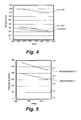
- Figure 4 shows, in a corresponding manner, graphs illustrating how the production of the crusher depends on the cycle frequency of the crushing cone 4.
- the figure shows separate graphs for crushed material with grain sizes of smaller than 4 mm, 4 to 10 mm, and greater than 10 mm. From the figure, it can be seen that the production reduces as the cycle frequency of the crushing cone 4 increases. Also this correlation is substantially linear.
- Figure 5 shows combined graphs illustrating how the capacity of the crusher and the power input in the actuator 10 are dependent on the cycle frequency of the crushing cone 4. As can be seen from the figure, a high capacity is achieved but more power is required at low cycle frequencies. In a corresponding manner, less power is required but a lower capacity is obtained at higher frequencies. Also these graphs are substantially linear.
- Figure 6 and 7 show how the frequency affects the grain size distribution of the crushed material, the other crushing conditions remaining constant.
- the frequency is high, and in Fig. 7 , the frequency is lower.
- the crushed material comprises relatively more small-sized particles than when the frequency is lower.
- Figure 8 illustrates the correlation between the capacity of the crusher and the cycle frequency of the crushing means 4. It can be seen from the figure that there is an optimum point n o at which the capacity of the crusher reaches a maximum. If necessary, the optimum point n o can be determined by experiments; in other words, by altering the frequency and simultaneously observing the capacity of the crusher. By examining the changes in the capacity, it is possible to determine the optimum point n o . Furthermore, there is a frequency range n 1 -n 2 , within which the frequency should be in practice, for the crusher to function as desired.
- the power input in the actuator 10 and the crushing force of the crusher behave essentially in a similar way when the cycle frequency of the crushing cone 4 changes.
- the adjustment of the cycle frequency of the crushing cone 4 may be based solely on the power input in the actuator 10 or the crushing force.
- the adjustment of the cycle frequency of the crushing cone 4 is based both on the power input in the actuator 10 and the crushing force of the crusher, wherein, in some cases, a better usability is achieved by monitoring several variables.
- the aim is to find the lowest possible cycle frequency of the crushing cone 4 with the power input of the crusher, because in this way, a high production of crushed material is typically achieved.
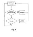
- the lowest cycle frequency is defined, at which the power input in the actuator 10 and/or the crushing force remain below the maximum level. After this, the cycle frequency is adjusted to the defined value.
- the principle of this kind of an approach is shown in the flow chart of Fig. 9 .
- the highest available power of the actuator is determined, and the cycle frequency is adjusted in such a way that the crushing force and/or the power of the actuator 10 correspond substantially to said highest available crushing force and/or power.
- the data (limit value) indicating the highest available crushing force and/or power input in the actuator 10 is in a computer program.
- the measurement data is compared to the limit value by software, and the cycle frequency is adjusted on the basis of the comparison.
- the limit value can be determined for each application through trial or by inputting the desired limit value separately.
- the solution of adjusting the frequency of the crushing cone 4 can also be combined with other control arrangements, such as the adjustment of the settings.
- changing the settings of the crushing blades will affect the power input in the actuator and/or the crushing force of the crushing unit 1.
- the cycle frequency of the crushing cone is changed, if necessary, to correspond to the changed settings when the settings are changed.
- the frequency of the crusher is adjusted to adjust the particle size distribution of the crushed material.
- the particle size distribution of the crushed material is adjusted as desired by operating the crusher at various frequencies.
- the frequency can be changed at short intervals between two or more values.
- the frequency can be changed at short intervals between two or more values.
- the frequency can be changed at short intervals between two or more values.
- the above-described arrangement for adjusting the frequency of the crushing blade 4 is suitable for use in various cone crushers, such as, for example, crushers with a long stroke or a short stroke, as well as in other crushers, such as, for example, impact crushers and jaw crushers.
- the arrangement for adjusting the frequency is substantially independent of the stroke of the crusher, because the adjustment is advantageously based on the crushing force and/or the power input in the actuator 10, which are substantially not dependent on the stroke of the crusher.
Landscapes
- Engineering & Computer Science (AREA)
- Food Science & Technology (AREA)
- Mechanical Engineering (AREA)
- Crushing And Grinding (AREA)
- Disintegrating Or Milling (AREA)
Applications Claiming Priority (1)
| Application Number | Priority Date | Filing Date | Title |
|---|---|---|---|
| PCT/FI2007/050193 WO2008122689A1 (en) | 2007-04-05 | 2007-04-05 | Control method for a crusher and a crusher |
Publications (3)
| Publication Number | Publication Date |
|---|---|
| EP2142301A1 EP2142301A1 (en) | 2010-01-13 |
| EP2142301A4 EP2142301A4 (en) | 2011-12-28 |
| EP2142301B1 true EP2142301B1 (en) | 2014-08-13 |
Family
ID=39830509
Family Applications (1)
| Application Number | Title | Priority Date | Filing Date |
|---|---|---|---|
| EP07730680.1A Active EP2142301B1 (en) | 2007-04-05 | 2007-04-05 | Control method for a crusher and a crusher |
Country Status (9)
| Country | Link |
|---|---|
| US (1) | US8899502B2 (https=) |
| EP (1) | EP2142301B1 (https=) |
| JP (1) | JP5283020B2 (https=) |
| CN (1) | CN101730592B (https=) |
| AU (1) | AU2007350808B2 (https=) |
| BR (1) | BRPI0721556B8 (https=) |
| IN (1) | IN2009KN03523A (https=) |
| RU (1) | RU2508948C2 (https=) |
| WO (1) | WO2008122689A1 (https=) |
Families Citing this family (16)
| Publication number | Priority date | Publication date | Assignee | Title |
|---|---|---|---|---|
| US7748655B2 (en) * | 2007-06-15 | 2010-07-06 | Riley Power, Inc. | Crusher block assembly for particulate size reduction system |
| DE102010012620A1 (de) | 2010-03-24 | 2011-09-29 | Siemens Aktiengesellschaft | Verfahren zum Betrieb einer Mühle |
| CN105478220A (zh) * | 2016-01-19 | 2016-04-13 | 中国黄金集团内蒙古矿业有限公司 | 矿石破碎系统及破碎机的控制方法 |
| CN105921251B (zh) * | 2016-05-03 | 2018-08-28 | 泰州三页混凝土有限公司 | 散装物料输送系统、移动式破碎机及其控制系统、方法 |
| CN105728167B (zh) * | 2016-05-03 | 2018-06-26 | 江苏鹏飞集团股份有限公司 | 移动式单辊破碎机和其控制方法、物料处理系统 |
| CN105728168B (zh) * | 2016-05-03 | 2018-05-25 | 江苏省机械研究设计院有限责任公司 | 散装物料输送系统、移动单辊破碎机和其控制方法 |
| CN105772206B (zh) * | 2016-05-03 | 2018-08-17 | 泰州市永欣金属有限公司 | 物料处理系统、移动式单辊破碎机的控制系统及控制方法 |
| CN105728103B (zh) * | 2016-05-03 | 2018-10-12 | 中材海外工程有限公司 | 移动式单辊破碎机及其控制方法和系统、物料处理系统 |
| US11027287B2 (en) | 2018-07-30 | 2021-06-08 | Metso Minerals Industries, Inc. | Gyratory crusher including a variable speed drive and control system |
| CN109046735B (zh) * | 2018-10-24 | 2020-06-30 | 江苏丰尚智能科技有限公司 | 一种粉碎加工过程中自动调节产品粒度的装置及其方法 |
| GB2588423B (en) * | 2019-10-23 | 2022-03-02 | Terex Gb Ltd | Cone crusher |
| JP6765559B1 (ja) * | 2020-03-19 | 2020-10-07 | 株式会社東宏 | 岩塊サイズの最適化システム、最適化方法、プログラム、及び記録媒体 |
| CN112718222A (zh) * | 2020-12-03 | 2021-04-30 | 南昌矿山机械有限公司 | 一种用于液压圆锥破碎机正压防尘系统风压智能控制方法 |
| CN113351354B (zh) * | 2021-05-31 | 2022-02-08 | 江苏邦鼎科技有限公司 | 一种基于物料颗粒运动轨迹的粉碎方法及系统 |
| KR102555690B1 (ko) * | 2021-10-27 | 2023-07-14 | 주식회사 에스피알 | 폐플라스틱 초저온 동결 파쇄 시스템의 최적화 방법 |
| CN114247735B (zh) * | 2021-11-10 | 2023-12-19 | 山西新科联环境技术有限公司 | 一种混合固体废物资源化处理方法 |
Citations (1)
| Publication number | Priority date | Publication date | Assignee | Title |
|---|---|---|---|---|
| JPH0563646U (ja) * | 1992-02-05 | 1993-08-24 | ラサ工業株式会社 | 慣性円錐破砕機の破砕力制御装置 |
Family Cites Families (18)
| Publication number | Priority date | Publication date | Assignee | Title |
|---|---|---|---|---|
| JPS5435460A (en) * | 1977-08-23 | 1979-03-15 | Kobe Steel Ltd | Crusher with automatic controller |
| JPS5645766A (en) | 1979-09-20 | 1981-04-25 | Kobe Steel Ltd | Method of controlling operation of corn crusher |
| SU1101303A1 (ru) * | 1983-04-07 | 1984-07-07 | Свердловский Ордена Трудового Красного Знамени Горный Институт Им.В.В.Вахрушева | Система регулировани режима работы дробилки |
| JPS6271554A (ja) * | 1985-09-25 | 1987-04-02 | 川崎重工業株式会社 | 円筒型粉砕機の運転制御方法 |
| JP2826398B2 (ja) | 1991-09-04 | 1998-11-18 | 日本電気株式会社 | 光中継システムにおけるループバック方式 |
| GB9302049D0 (en) | 1993-02-03 | 1993-03-24 | Rhone Poulenc Agriculture | Compositions of new matter |
| US5718391A (en) * | 1996-10-15 | 1998-02-17 | Cedarapids, Inc. | Gyratory crusher having dynamically adjustable stroke |
| JPH10272375A (ja) * | 1997-03-31 | 1998-10-13 | Kurimoto Ltd | 旋動式破砕機の制御方法 |
| US6213418B1 (en) * | 1998-10-14 | 2001-04-10 | Martin Marietta Materials, Inc. | Variable throw eccentric cone crusher and method for operating the same |
| JP2002346427A (ja) | 2001-05-24 | 2002-12-03 | Hitachi Constr Mach Co Ltd | 自走式木材破砕機及び自走式木材破砕機の制御方法並びにそのプログラム |
| RU2204438C1 (ru) * | 2001-09-14 | 2003-05-20 | Зобнин Борис Борисович | Устройство для автоматического управления процессом дробления материала |
| SE524784C2 (sv) * | 2003-02-10 | 2004-10-05 | Sandvik Ab | Sätt och anordning för styrning av kross samt visarinstrument för indikering av belastning av kross |
| DE10333359B3 (de) | 2003-07-23 | 2005-01-20 | Vecoplan Maschinenfabrik Gmbh & Co. Kg | Zerkleinerungsvorrichtung für Abfälle |
| FI116277B (fi) * | 2003-09-26 | 2005-10-31 | Metso Paper Inc | Hakkuri- tai murskainlaitteisto, erityisesti lastuhakkuri |
| US7279037B2 (en) * | 2004-02-12 | 2007-10-09 | Engelhard Corporation | Process and products of chinese kaolin |
| SE526895C2 (sv) * | 2004-03-25 | 2005-11-15 | Sandvik Intellectual Property | Sätt och anordning för styrning av en kross |
| BRPI0520666B8 (pt) * | 2005-11-02 | 2023-04-18 | Metso Minerals Inc | Método para controlar um britador, e, britador |
| ITMI20061232A1 (it) | 2006-06-26 | 2007-12-27 | Saeco Ipr Ltd | Metodo di rilevazione della quantita' di grani in un dispositivo di macinatura |
-
2007
- 2007-04-05 IN IN3523KON2009 patent/IN2009KN03523A/en unknown
- 2007-04-05 WO PCT/FI2007/050193 patent/WO2008122689A1/en not_active Ceased
- 2007-04-05 US US12/450,609 patent/US8899502B2/en active Active
- 2007-04-05 EP EP07730680.1A patent/EP2142301B1/en active Active
- 2007-04-05 CN CN2007800532124A patent/CN101730592B/zh active Active
- 2007-04-05 BR BRPI0721556A patent/BRPI0721556B8/pt active IP Right Grant
- 2007-04-05 AU AU2007350808A patent/AU2007350808B2/en active Active
- 2007-04-05 JP JP2010501538A patent/JP5283020B2/ja active Active
- 2007-04-05 RU RU2009137456/02A patent/RU2508948C2/ru not_active Application Discontinuation
Patent Citations (1)
| Publication number | Priority date | Publication date | Assignee | Title |
|---|---|---|---|---|
| JPH0563646U (ja) * | 1992-02-05 | 1993-08-24 | ラサ工業株式会社 | 慣性円錐破砕機の破砕力制御装置 |
Also Published As
| Publication number | Publication date |
|---|---|
| AU2007350808B2 (en) | 2012-10-25 |
| RU2508948C2 (ru) | 2014-03-10 |
| US20100059610A1 (en) | 2010-03-11 |
| EP2142301A1 (en) | 2010-01-13 |
| CN101730592A (zh) | 2010-06-09 |
| AU2007350808A1 (en) | 2008-10-16 |
| AU2007350808A2 (en) | 2009-12-24 |
| JP5283020B2 (ja) | 2013-09-04 |
| EP2142301A4 (en) | 2011-12-28 |
| WO2008122689A1 (en) | 2008-10-16 |
| BRPI0721556A2 (pt) | 2013-01-08 |
| BRPI0721556B1 (pt) | 2020-11-10 |
| IN2009KN03523A (https=) | 2015-08-28 |
| RU2009137456A (ru) | 2011-06-10 |
| US8899502B2 (en) | 2014-12-02 |
| JP2010523309A (ja) | 2010-07-15 |
| CN101730592B (zh) | 2013-07-03 |
| BRPI0721556B8 (pt) | 2023-04-18 |
Similar Documents
| Publication | Publication Date | Title |
|---|---|---|
| EP2142301B1 (en) | Control method for a crusher and a crusher | |
| EP2556891B1 (en) | A method and a device for sensing the properties of a material to be crushed | |
| US8109454B2 (en) | Crusher, method for crushing material and method for controlling a crusher | |
| US9498779B2 (en) | Method for regulating the roll gap pressure of a roller press | |
| CN102348508A (zh) | 控制回转破碎机运行的方法和装置 | |
| CN101678359A (zh) | 破碎装置及控制该破碎装置的方法 | |
| WO2015062824A1 (en) | Method and system for controlling a jaw crusher | |
| WO2009065995A1 (en) | Crusher | |
| CN105283251A (zh) | 破碎机的操作方法、破碎系统以及破碎站 | |
| CN118244704A (zh) | 一种检测反馈及动态设备参数调整的控制方法及系统 | |
| JP2025054052A (ja) | 破砕装置 | |
| CN100438982C (zh) | 控制破碎机的方法和装置 | |
| JP7151512B2 (ja) | 竪型粉砕機及びその運転方法 | |
| CN110193398A (zh) | 一种动颚冲程调节装置及其颚式破碎机 | |
| KR20250092437A (ko) | 광물 파쇄용 롤밀 장치 | |
| CN118634925A (zh) | 一种双动力纳米棒销砂磨机及其控制方法 | |
| CN105750057A (zh) | Sc振动冲击式破碎机 | |
| CN107377084A (zh) | 一种制砂机 | |
| AU2014344095A1 (en) | Method and system for controlling a jaw crusher |
Legal Events
| Date | Code | Title | Description |
|---|---|---|---|
| PUAI | Public reference made under article 153(3) epc to a published international application that has entered the european phase |
Free format text: ORIGINAL CODE: 0009012 |
|
| 17P | Request for examination filed |
Effective date: 20091005 |
|
| AK | Designated contracting states |
Kind code of ref document: A1 Designated state(s): AT BE BG CH CY CZ DE DK EE ES FI FR GB GR HU IE IS IT LI LT LU LV MC MT NL PL PT RO SE SI SK TR |
|
| DAX | Request for extension of the european patent (deleted) | ||
| REG | Reference to a national code |
Ref country code: SE Ref legal event code: TRCL |
|
| A4 | Supplementary search report drawn up and despatched |
Effective date: 20111125 |
|
| RIC1 | Information provided on ipc code assigned before grant |
Ipc: B02C 2/04 20060101ALI20111121BHEP Ipc: B02C 25/00 20060101AFI20111121BHEP |
|
| 17Q | First examination report despatched |
Effective date: 20121023 |
|
| GRAP | Despatch of communication of intention to grant a patent |
Free format text: ORIGINAL CODE: EPIDOSNIGR1 |
|
| INTG | Intention to grant announced |
Effective date: 20140324 |
|
| GRAS | Grant fee paid |
Free format text: ORIGINAL CODE: EPIDOSNIGR3 |
|
| GRAA | (expected) grant |
Free format text: ORIGINAL CODE: 0009210 |
|
| AK | Designated contracting states |
Kind code of ref document: B1 Designated state(s): AT BE BG CH CY CZ DE DK EE ES FI FR GB GR HU IE IS IT LI LT LU LV MC MT NL PL PT RO SE SI SK TR |
|
| REG | Reference to a national code |
Ref country code: GB Ref legal event code: FG4D |
|
| REG | Reference to a national code |
Ref country code: CH Ref legal event code: EP Ref country code: AT Ref legal event code: REF Ref document number: 681862 Country of ref document: AT Kind code of ref document: T Effective date: 20140815 |
|
| REG | Reference to a national code |
Ref country code: IE Ref legal event code: FG4D |
|
| REG | Reference to a national code |
Ref country code: DE Ref legal event code: R096 Ref document number: 602007038080 Country of ref document: DE Effective date: 20140918 |
|
| REG | Reference to a national code |
Ref country code: SE Ref legal event code: TRGR |
|
| REG | Reference to a national code |
Ref country code: NL Ref legal event code: VDEP Effective date: 20140813 |
|
| REG | Reference to a national code |
Ref country code: AT Ref legal event code: MK05 Ref document number: 681862 Country of ref document: AT Kind code of ref document: T Effective date: 20140813 |
|
| REG | Reference to a national code |
Ref country code: LT Ref legal event code: MG4D |
|
| PG25 | Lapsed in a contracting state [announced via postgrant information from national office to epo] |
Ref country code: LT Free format text: LAPSE BECAUSE OF FAILURE TO SUBMIT A TRANSLATION OF THE DESCRIPTION OR TO PAY THE FEE WITHIN THE PRESCRIBED TIME-LIMIT Effective date: 20140813 Ref country code: GR Free format text: LAPSE BECAUSE OF FAILURE TO SUBMIT A TRANSLATION OF THE DESCRIPTION OR TO PAY THE FEE WITHIN THE PRESCRIBED TIME-LIMIT Effective date: 20141114 Ref country code: ES Free format text: LAPSE BECAUSE OF FAILURE TO SUBMIT A TRANSLATION OF THE DESCRIPTION OR TO PAY THE FEE WITHIN THE PRESCRIBED TIME-LIMIT Effective date: 20140813 Ref country code: PT Free format text: LAPSE BECAUSE OF FAILURE TO SUBMIT A TRANSLATION OF THE DESCRIPTION OR TO PAY THE FEE WITHIN THE PRESCRIBED TIME-LIMIT Effective date: 20141215 Ref country code: BG Free format text: LAPSE BECAUSE OF FAILURE TO SUBMIT A TRANSLATION OF THE DESCRIPTION OR TO PAY THE FEE WITHIN THE PRESCRIBED TIME-LIMIT Effective date: 20141113 Ref country code: FI Free format text: LAPSE BECAUSE OF FAILURE TO SUBMIT A TRANSLATION OF THE DESCRIPTION OR TO PAY THE FEE WITHIN THE PRESCRIBED TIME-LIMIT Effective date: 20140813 |
|
| PG25 | Lapsed in a contracting state [announced via postgrant information from national office to epo] |
Ref country code: CY Free format text: LAPSE BECAUSE OF FAILURE TO SUBMIT A TRANSLATION OF THE DESCRIPTION OR TO PAY THE FEE WITHIN THE PRESCRIBED TIME-LIMIT Effective date: 20140813 Ref country code: LV Free format text: LAPSE BECAUSE OF FAILURE TO SUBMIT A TRANSLATION OF THE DESCRIPTION OR TO PAY THE FEE WITHIN THE PRESCRIBED TIME-LIMIT Effective date: 20140813 Ref country code: AT Free format text: LAPSE BECAUSE OF FAILURE TO SUBMIT A TRANSLATION OF THE DESCRIPTION OR TO PAY THE FEE WITHIN THE PRESCRIBED TIME-LIMIT Effective date: 20140813 Ref country code: IS Free format text: LAPSE BECAUSE OF FAILURE TO SUBMIT A TRANSLATION OF THE DESCRIPTION OR TO PAY THE FEE WITHIN THE PRESCRIBED TIME-LIMIT Effective date: 20141213 |
|
| PG25 | Lapsed in a contracting state [announced via postgrant information from national office to epo] |
Ref country code: NL Free format text: LAPSE BECAUSE OF FAILURE TO SUBMIT A TRANSLATION OF THE DESCRIPTION OR TO PAY THE FEE WITHIN THE PRESCRIBED TIME-LIMIT Effective date: 20140813 |
|
| PG25 | Lapsed in a contracting state [announced via postgrant information from national office to epo] |
Ref country code: SK Free format text: LAPSE BECAUSE OF FAILURE TO SUBMIT A TRANSLATION OF THE DESCRIPTION OR TO PAY THE FEE WITHIN THE PRESCRIBED TIME-LIMIT Effective date: 20140813 Ref country code: EE Free format text: LAPSE BECAUSE OF FAILURE TO SUBMIT A TRANSLATION OF THE DESCRIPTION OR TO PAY THE FEE WITHIN THE PRESCRIBED TIME-LIMIT Effective date: 20140813 Ref country code: RO Free format text: LAPSE BECAUSE OF FAILURE TO SUBMIT A TRANSLATION OF THE DESCRIPTION OR TO PAY THE FEE WITHIN THE PRESCRIBED TIME-LIMIT Effective date: 20140813 Ref country code: CZ Free format text: LAPSE BECAUSE OF FAILURE TO SUBMIT A TRANSLATION OF THE DESCRIPTION OR TO PAY THE FEE WITHIN THE PRESCRIBED TIME-LIMIT Effective date: 20140813 Ref country code: DK Free format text: LAPSE BECAUSE OF FAILURE TO SUBMIT A TRANSLATION OF THE DESCRIPTION OR TO PAY THE FEE WITHIN THE PRESCRIBED TIME-LIMIT Effective date: 20140813 Ref country code: IT Free format text: LAPSE BECAUSE OF FAILURE TO SUBMIT A TRANSLATION OF THE DESCRIPTION OR TO PAY THE FEE WITHIN THE PRESCRIBED TIME-LIMIT Effective date: 20140813 |
|
| REG | Reference to a national code |
Ref country code: DE Ref legal event code: R097 Ref document number: 602007038080 Country of ref document: DE |
|
| PG25 | Lapsed in a contracting state [announced via postgrant information from national office to epo] |
Ref country code: PL Free format text: LAPSE BECAUSE OF FAILURE TO SUBMIT A TRANSLATION OF THE DESCRIPTION OR TO PAY THE FEE WITHIN THE PRESCRIBED TIME-LIMIT Effective date: 20140813 |
|
| PLBE | No opposition filed within time limit |
Free format text: ORIGINAL CODE: 0009261 |
|
| STAA | Information on the status of an ep patent application or granted ep patent |
Free format text: STATUS: NO OPPOSITION FILED WITHIN TIME LIMIT |
|
| 26N | No opposition filed |
Effective date: 20150515 |
|
| REG | Reference to a national code |
Ref country code: DE Ref legal event code: R082 Ref document number: 602007038080 Country of ref document: DE Representative=s name: GRAMM, LINS & PARTNER PATENT- UND RECHTSANWAEL, DE |
|
| PG25 | Lapsed in a contracting state [announced via postgrant information from national office to epo] |
Ref country code: SI Free format text: LAPSE BECAUSE OF FAILURE TO SUBMIT A TRANSLATION OF THE DESCRIPTION OR TO PAY THE FEE WITHIN THE PRESCRIBED TIME-LIMIT Effective date: 20140813 Ref country code: MC Free format text: LAPSE BECAUSE OF FAILURE TO SUBMIT A TRANSLATION OF THE DESCRIPTION OR TO PAY THE FEE WITHIN THE PRESCRIBED TIME-LIMIT Effective date: 20140813 Ref country code: LU Free format text: LAPSE BECAUSE OF FAILURE TO SUBMIT A TRANSLATION OF THE DESCRIPTION OR TO PAY THE FEE WITHIN THE PRESCRIBED TIME-LIMIT Effective date: 20150405 |
|
| REG | Reference to a national code |
Ref country code: CH Ref legal event code: PL |
|
| REG | Reference to a national code |
Ref country code: IE Ref legal event code: MM4A |
|
| PG25 | Lapsed in a contracting state [announced via postgrant information from national office to epo] |
Ref country code: LI Free format text: LAPSE BECAUSE OF NON-PAYMENT OF DUE FEES Effective date: 20150430 Ref country code: CH Free format text: LAPSE BECAUSE OF NON-PAYMENT OF DUE FEES Effective date: 20150430 |
|
| REG | Reference to a national code |
Ref country code: FR Ref legal event code: PLFP Year of fee payment: 10 |
|
| PG25 | Lapsed in a contracting state [announced via postgrant information from national office to epo] |
Ref country code: IE Free format text: LAPSE BECAUSE OF NON-PAYMENT OF DUE FEES Effective date: 20150405 |
|
| PG25 | Lapsed in a contracting state [announced via postgrant information from national office to epo] |
Ref country code: BE Free format text: LAPSE BECAUSE OF FAILURE TO SUBMIT A TRANSLATION OF THE DESCRIPTION OR TO PAY THE FEE WITHIN THE PRESCRIBED TIME-LIMIT Effective date: 20140813 |
|
| PG25 | Lapsed in a contracting state [announced via postgrant information from national office to epo] |
Ref country code: MT Free format text: LAPSE BECAUSE OF FAILURE TO SUBMIT A TRANSLATION OF THE DESCRIPTION OR TO PAY THE FEE WITHIN THE PRESCRIBED TIME-LIMIT Effective date: 20140813 |
|
| REG | Reference to a national code |
Ref country code: FR Ref legal event code: PLFP Year of fee payment: 11 |
|
| PG25 | Lapsed in a contracting state [announced via postgrant information from national office to epo] |
Ref country code: HU Free format text: LAPSE BECAUSE OF FAILURE TO SUBMIT A TRANSLATION OF THE DESCRIPTION OR TO PAY THE FEE WITHIN THE PRESCRIBED TIME-LIMIT; INVALID AB INITIO Effective date: 20070405 |
|
| PG25 | Lapsed in a contracting state [announced via postgrant information from national office to epo] |
Ref country code: TR Free format text: LAPSE BECAUSE OF FAILURE TO SUBMIT A TRANSLATION OF THE DESCRIPTION OR TO PAY THE FEE WITHIN THE PRESCRIBED TIME-LIMIT Effective date: 20140813 |
|
| REG | Reference to a national code |
Ref country code: FR Ref legal event code: PLFP Year of fee payment: 12 |
|
| REG | Reference to a national code |
Ref country code: DE Ref legal event code: R081 Ref document number: 602007038080 Country of ref document: DE Owner name: METSO OUTOTEC FINLAND OY, FI Free format text: FORMER OWNER: METSO MINERALS, INC., HELSINKI, FI Ref country code: DE Ref legal event code: R082 Ref document number: 602007038080 Country of ref document: DE Representative=s name: HOFFMANN - EITLE PATENT- UND RECHTSANWAELTE PA, DE Ref country code: DE Ref legal event code: R082 Ref document number: 602007038080 Country of ref document: DE Representative=s name: HOFFMANN EITLE PATENT- UND RECHTSANWAELTE PART, DE |
|
| PGFP | Annual fee paid to national office [announced via postgrant information from national office to epo] |
Ref country code: DE Payment date: 20250305 Year of fee payment: 19 |
|
| PGFP | Annual fee paid to national office [announced via postgrant information from national office to epo] |
Ref country code: SE Payment date: 20260312 Year of fee payment: 20 |
|
| PGFP | Annual fee paid to national office [announced via postgrant information from national office to epo] |
Ref country code: GB Payment date: 20260223 Year of fee payment: 20 |
|
| PGFP | Annual fee paid to national office [announced via postgrant information from national office to epo] |
Ref country code: FR Payment date: 20260323 Year of fee payment: 20 |