EP2142102B1 - Tissue harvesting - Google Patents
Tissue harvesting Download PDFInfo
- Publication number
- EP2142102B1 EP2142102B1 EP08745282A EP08745282A EP2142102B1 EP 2142102 B1 EP2142102 B1 EP 2142102B1 EP 08745282 A EP08745282 A EP 08745282A EP 08745282 A EP08745282 A EP 08745282A EP 2142102 B1 EP2142102 B1 EP 2142102B1
- Authority
- EP
- European Patent Office
- Prior art keywords
- tissue
- scaffold
- tubular member
- housing
- filter
- Prior art date
- Legal status (The legal status is an assumption and is not a legal conclusion. Google has not performed a legal analysis and makes no representation as to the accuracy of the status listed.)
- Not-in-force
Links
- 238000003306 harvesting Methods 0.000 title claims description 18
- 239000002407 tissue scaffold Substances 0.000 claims abstract description 178
- 239000012530 fluid Substances 0.000 claims description 114
- 230000037361 pathway Effects 0.000 claims description 46
- 238000004891 communication Methods 0.000 claims description 20
- 210000001519 tissue Anatomy 0.000 description 318
- 210000000577 adipose tissue Anatomy 0.000 description 30
- 238000000034 method Methods 0.000 description 28
- 210000000845 cartilage Anatomy 0.000 description 22
- 239000000463 material Substances 0.000 description 17
- 239000012634 fragment Substances 0.000 description 16
- 230000006378 damage Effects 0.000 description 14
- 239000002245 particle Substances 0.000 description 13
- 239000007943 implant Substances 0.000 description 11
- 239000000853 adhesive Substances 0.000 description 10
- 230000001070 adhesive effect Effects 0.000 description 10
- 238000001356 surgical procedure Methods 0.000 description 10
- 230000008439 repair process Effects 0.000 description 9
- 208000014674 injury Diseases 0.000 description 8
- 210000005222 synovial tissue Anatomy 0.000 description 8
- 210000000988 bone and bone Anatomy 0.000 description 7
- 210000004027 cell Anatomy 0.000 description 7
- 238000010168 coupling process Methods 0.000 description 7
- 230000007547 defect Effects 0.000 description 7
- 238000002513 implantation Methods 0.000 description 7
- 230000006835 compression Effects 0.000 description 5
- 238000007906 compression Methods 0.000 description 5
- 230000008878 coupling Effects 0.000 description 5
- 238000005859 coupling reaction Methods 0.000 description 5
- 238000005520 cutting process Methods 0.000 description 5
- 230000003902 lesion Effects 0.000 description 5
- 230000013011 mating Effects 0.000 description 5
- 210000000130 stem cell Anatomy 0.000 description 5
- 208000027418 Wounds and injury Diseases 0.000 description 4
- 238000000605 extraction Methods 0.000 description 4
- 239000003292 glue Substances 0.000 description 4
- 201000008482 osteoarthritis Diseases 0.000 description 4
- 239000011148 porous material Substances 0.000 description 4
- 230000008733 trauma Effects 0.000 description 4
- 239000007767 bonding agent Substances 0.000 description 3
- 210000004417 patella Anatomy 0.000 description 3
- 230000008569 process Effects 0.000 description 3
- 208000024891 symptom Diseases 0.000 description 3
- 210000001258 synovial membrane Anatomy 0.000 description 3
- 208000032843 Hemorrhage Diseases 0.000 description 2
- 230000000903 blocking effect Effects 0.000 description 2
- 230000007850 degeneration Effects 0.000 description 2
- 230000003412 degenerative effect Effects 0.000 description 2
- 238000013150 knee replacement Methods 0.000 description 2
- 230000014759 maintenance of location Effects 0.000 description 2
- 238000004519 manufacturing process Methods 0.000 description 2
- 239000002184 metal Substances 0.000 description 2
- 238000000465 moulding Methods 0.000 description 2
- 230000035515 penetration Effects 0.000 description 2
- 239000004033 plastic Substances 0.000 description 2
- 230000004044 response Effects 0.000 description 2
- 230000017423 tissue regeneration Effects 0.000 description 2
- 206010065687 Bone loss Diseases 0.000 description 1
- 229920004943 Delrin® Polymers 0.000 description 1
- 239000004677 Nylon Substances 0.000 description 1
- 208000008589 Obesity Diseases 0.000 description 1
- 206010030113 Oedema Diseases 0.000 description 1
- 208000006735 Periostitis Diseases 0.000 description 1
- 208000013201 Stress fracture Diseases 0.000 description 1
- 239000006096 absorbing agent Substances 0.000 description 1
- 238000009825 accumulation Methods 0.000 description 1
- 238000004026 adhesive bonding Methods 0.000 description 1
- 230000002293 adipogenic effect Effects 0.000 description 1
- 230000000735 allogeneic effect Effects 0.000 description 1
- 210000001188 articular cartilage Anatomy 0.000 description 1
- 230000000712 assembly Effects 0.000 description 1
- 238000000429 assembly Methods 0.000 description 1
- 238000001574 biopsy Methods 0.000 description 1
- 230000000740 bleeding effect Effects 0.000 description 1
- 238000009583 bone marrow aspiration Methods 0.000 description 1
- 210000001612 chondrocyte Anatomy 0.000 description 1
- 230000002648 chondrogenic effect Effects 0.000 description 1
- 238000010276 construction Methods 0.000 description 1
- 210000000033 corpus adiposum buccae Anatomy 0.000 description 1
- 239000002537 cosmetic Substances 0.000 description 1
- 238000001804 debridement Methods 0.000 description 1
- 230000001419 dependent effect Effects 0.000 description 1
- 238000000151 deposition Methods 0.000 description 1
- 230000001627 detrimental effect Effects 0.000 description 1
- 230000037213 diet Effects 0.000 description 1
- 235000005911 diet Nutrition 0.000 description 1
- 201000010099 disease Diseases 0.000 description 1
- 208000037265 diseases, disorders, signs and symptoms Diseases 0.000 description 1
- 238000009826 distribution Methods 0.000 description 1
- 230000007613 environmental effect Effects 0.000 description 1
- 210000000968 fibrocartilage Anatomy 0.000 description 1
- 238000001914 filtration Methods 0.000 description 1
- 230000035876 healing Effects 0.000 description 1
- 230000028993 immune response Effects 0.000 description 1
- 230000002163 immunogen Effects 0.000 description 1
- 238000000338 in vitro Methods 0.000 description 1
- 230000008595 infiltration Effects 0.000 description 1
- 238000001764 infiltration Methods 0.000 description 1
- 238000002347 injection Methods 0.000 description 1
- 239000007924 injection Substances 0.000 description 1
- 238000001746 injection moulding Methods 0.000 description 1
- 210000005067 joint tissue Anatomy 0.000 description 1
- 210000002414 leg Anatomy 0.000 description 1
- 239000000314 lubricant Substances 0.000 description 1
- 210000002540 macrophage Anatomy 0.000 description 1
- 210000000032 mammalian fat body Anatomy 0.000 description 1
- 230000005541 medical transmission Effects 0.000 description 1
- 239000007769 metal material Substances 0.000 description 1
- 238000012986 modification Methods 0.000 description 1
- 230000004048 modification Effects 0.000 description 1
- 210000003205 muscle Anatomy 0.000 description 1
- 230000001114 myogenic effect Effects 0.000 description 1
- 210000000944 nerve tissue Anatomy 0.000 description 1
- 230000001272 neurogenic effect Effects 0.000 description 1
- 229910052755 nonmetal Inorganic materials 0.000 description 1
- 229920001778 nylon Polymers 0.000 description 1
- 235000020824 obesity Nutrition 0.000 description 1
- 210000002221 olecranon process Anatomy 0.000 description 1
- 230000000399 orthopedic effect Effects 0.000 description 1
- 230000002188 osteogenic effect Effects 0.000 description 1
- 231100000915 pathological change Toxicity 0.000 description 1
- 230000036285 pathological change Effects 0.000 description 1
- 239000008188 pellet Substances 0.000 description 1
- 210000003460 periosteum Anatomy 0.000 description 1
- 230000009467 reduction Effects 0.000 description 1
- 239000000565 sealant Substances 0.000 description 1
- 230000035939 shock Effects 0.000 description 1
- 210000004872 soft tissue Anatomy 0.000 description 1
- 210000005065 subchondral bone plate Anatomy 0.000 description 1
- 239000000725 suspension Substances 0.000 description 1
- 230000001225 therapeutic effect Effects 0.000 description 1
Images
























Classifications
-
- C—CHEMISTRY; METALLURGY
- C12—BIOCHEMISTRY; BEER; SPIRITS; WINE; VINEGAR; MICROBIOLOGY; ENZYMOLOGY; MUTATION OR GENETIC ENGINEERING
- C12N—MICROORGANISMS OR ENZYMES; COMPOSITIONS THEREOF; PROPAGATING, PRESERVING, OR MAINTAINING MICROORGANISMS; MUTATION OR GENETIC ENGINEERING; CULTURE MEDIA
- C12N5/00—Undifferentiated human, animal or plant cells, e.g. cell lines; Tissues; Cultivation or maintenance thereof; Culture media therefor
- C12N5/06—Animal cells or tissues; Human cells or tissues
- C12N5/0602—Vertebrate cells
- C12N5/0652—Cells of skeletal and connective tissues; Mesenchyme
- C12N5/0653—Adipocytes; Adipose tissue
-
- A—HUMAN NECESSITIES
- A61—MEDICAL OR VETERINARY SCIENCE; HYGIENE
- A61B—DIAGNOSIS; SURGERY; IDENTIFICATION
- A61B17/00—Surgical instruments, devices or methods
- A61B17/16—Instruments for performing osteoclasis; Drills or chisels for bones; Trepans
- A61B17/1635—Instruments for performing osteoclasis; Drills or chisels for bones; Trepans for grafts, harvesting or transplants
-
- A—HUMAN NECESSITIES
- A61—MEDICAL OR VETERINARY SCIENCE; HYGIENE
- A61B—DIAGNOSIS; SURGERY; IDENTIFICATION
- A61B17/00—Surgical instruments, devices or methods
- A61B17/32—Surgical cutting instruments
- A61B17/320016—Endoscopic cutting instruments, e.g. arthroscopes, resectoscopes
- A61B17/32002—Endoscopic cutting instruments, e.g. arthroscopes, resectoscopes with continuously rotating, oscillating or reciprocating cutting instruments
-
- A—HUMAN NECESSITIES
- A61—MEDICAL OR VETERINARY SCIENCE; HYGIENE
- A61B—DIAGNOSIS; SURGERY; IDENTIFICATION
- A61B17/00—Surgical instruments, devices or methods
- A61B17/32—Surgical cutting instruments
- A61B17/3205—Excision instruments
-
- A—HUMAN NECESSITIES
- A61—MEDICAL OR VETERINARY SCIENCE; HYGIENE
- A61M—DEVICES FOR INTRODUCING MEDIA INTO, OR ONTO, THE BODY; DEVICES FOR TRANSDUCING BODY MEDIA OR FOR TAKING MEDIA FROM THE BODY; DEVICES FOR PRODUCING OR ENDING SLEEP OR STUPOR
- A61M1/00—Suction or pumping devices for medical purposes; Devices for carrying-off, for treatment of, or for carrying-over, body-liquids; Drainage systems
- A61M1/71—Suction drainage systems
- A61M1/79—Filters for solid matter
-
- A—HUMAN NECESSITIES
- A61—MEDICAL OR VETERINARY SCIENCE; HYGIENE
- A61B—DIAGNOSIS; SURGERY; IDENTIFICATION
- A61B10/00—Instruments for taking body samples for diagnostic purposes; Other methods or instruments for diagnosis, e.g. for vaccination diagnosis, sex determination or ovulation-period determination; Throat striking implements
- A61B10/02—Instruments for taking cell samples or for biopsy
- A61B10/0233—Pointed or sharp biopsy instruments
- A61B10/025—Pointed or sharp biopsy instruments for taking bone, bone marrow or cartilage samples
-
- A—HUMAN NECESSITIES
- A61—MEDICAL OR VETERINARY SCIENCE; HYGIENE
- A61B—DIAGNOSIS; SURGERY; IDENTIFICATION
- A61B10/00—Instruments for taking body samples for diagnostic purposes; Other methods or instruments for diagnosis, e.g. for vaccination diagnosis, sex determination or ovulation-period determination; Throat striking implements
- A61B10/02—Instruments for taking cell samples or for biopsy
- A61B10/0233—Pointed or sharp biopsy instruments
- A61B10/0283—Pointed or sharp biopsy instruments with vacuum aspiration, e.g. caused by retractable plunger or by connected syringe
-
- A—HUMAN NECESSITIES
- A61—MEDICAL OR VETERINARY SCIENCE; HYGIENE
- A61B—DIAGNOSIS; SURGERY; IDENTIFICATION
- A61B17/00—Surgical instruments, devices or methods
- A61B2017/00969—Surgical instruments, devices or methods used for transplantation
-
- A—HUMAN NECESSITIES
- A61—MEDICAL OR VETERINARY SCIENCE; HYGIENE
- A61B—DIAGNOSIS; SURGERY; IDENTIFICATION
- A61B2217/00—General characteristics of surgical instruments
- A61B2217/002—Auxiliary appliance
- A61B2217/005—Auxiliary appliance with suction drainage system
-
- A—HUMAN NECESSITIES
- A61—MEDICAL OR VETERINARY SCIENCE; HYGIENE
- A61M—DEVICES FOR INTRODUCING MEDIA INTO, OR ONTO, THE BODY; DEVICES FOR TRANSDUCING BODY MEDIA OR FOR TAKING MEDIA FROM THE BODY; DEVICES FOR PRODUCING OR ENDING SLEEP OR STUPOR
- A61M2202/00—Special media to be introduced, removed or treated
- A61M2202/0014—Special media to be introduced, removed or treated removed from the body
-
- A—HUMAN NECESSITIES
- A61—MEDICAL OR VETERINARY SCIENCE; HYGIENE
- A61M—DEVICES FOR INTRODUCING MEDIA INTO, OR ONTO, THE BODY; DEVICES FOR TRANSDUCING BODY MEDIA OR FOR TAKING MEDIA FROM THE BODY; DEVICES FOR PRODUCING OR ENDING SLEEP OR STUPOR
- A61M2202/00—Special media to be introduced, removed or treated
- A61M2202/08—Lipoids
Definitions
- the sleeve is configured to release the tissue scaffold upon application of a downward force applied to the sleeve.
- the sleeve is compliant and compresses around the tissue scaffold upon application of a force applied to the sleeve thereby allowing access to the tissue scaffold for removal from the sleeve.
- the apparatus further comprises a filter disposed within the housing of the tissue collection apparatus.
- the filter defines a set of openings having an opening size of up to about 600 ⁇ m to about 1mm, or of about 600 ⁇ m.
- the filter defines a plurality of openings having an opening size of about 2.4 mm, or of about 3 mm.
- a filter positioned between the elongate inner tubular member and the inlet of the housing.
- a hub is configured to receive a portion of the elongate outer tubular member and the inner tubular member.
- the hub includes a sidewall defining an aperture in fluid communication with the aspiration lumen of the elongate inner tubular member and the housing is configured to be coupled to the aperture such that the tissue scaffold is loaded with tissue during aspiration of the tissue from the aspiration lumen.
- a method in another general aspect, includes aspirating a cut tissue through an aspiration lumen of a cutter and loading a tissue scaffold of a tissue collection device with cut tissue under the application of an aspiration force applied through the tissue collection device to the aspiration lumen of the cutter to aspirate tissue therethrough.
- tissue collection device 1040 for use with the tissue harvesting assembly 100 includes a cylindrical transparent housing 1042 having a first end 1042a and a second end 1042b, a biodegradable, fluid permeable, implant material, or tissue scaffold 1046, and a sleeve 1052 surrounding a portion, for example, the circumference but not ends, of the tissue scaffold 1046 and disposed between the tissue scaffold 1046 and the housing 1042.
- the housing 1042 and the sleeve 1052 can be made from plastic or any other suitable material.
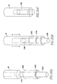
- FIG. 22A-22B An alternative tissue collection housing 2242 for use with the tissue collection device 1040 is shown in Figs. 22A-22B .
- the housing 2242 includes a cylindrical sleeve 2252 for holding the tissue scaffold 1046 within the housing 2242.
- the cylindrical sleeve 2252 is configured to be slidably received within the housing 2242 and held in place within a desired location within the housing 2242 by a frictional fit.
- the sleeve 2252 surrounds the entire exterior of the first region 1046a and second region 1046b of the tissue scaffold 1046 except for the face 1046d of the first region 1046a and the face 1046f of the second region 1046b, which are exposed to the interior 2243 of the housing 2242.
- Figs. 23A-23B illustrate an alternative configuration for placement of the tissue scaffold 1046 within the sleeve 2252.
- the sleeve 2252 surrounds the entire second region 1046b of the tissue scaffold 1046 but leaves the first region 1046a, including the face 1046d and the side portion 1046e, and the face 1046f of the second region 1046b, exposed to the interior 2243 of the housing 2242.
- tissue and the fluid enter the scaffold 1046 through the face 1046d, travel substantially axially through the first region 1046a and the second region 1046b, and any tissue that is not captured by the tissue scaffold 1046, exits along with the fluid through the face 1046f.
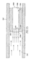
- the pathways 1070 allow for deep penetration of the tissue fragments along a desired path through the first region 1046a. This configuration provides a degree of controlled tissue loading to the tissue collection device 1040.
- a set of tissue-containing needles can be used to provide for controlled distribution of the tissue fragments into the first regions 1046a. The needles (not shown) pierce the first region 1046a, inject the tissue into the desired locations within the first region 1046a, and are retracted from the tissue scaffold 1046 following injection.
- the connectors 2044 and 2048 are removably coupled to the first and second ends 2042a, 2042b, respectively, of the housing 2042, using, for example, mating threaded connections (not shown) on the inlet connector 2044, the outlet connector 2048, and the housing 2042; adhesive; an interference friction fit between the ends of the housing 2042 and corresponding receiving portions (not shown) formed in the inlet connector 2044 and the outlet connector 2048; or other suitable methods.
- the connectors 2044, 2048 form a fluid-tight seal with the housing 2042.
- a tissue collection device 2040a includes a housing 3042 having a first housing portion 2043 and a second housing portion 2045 coupled together using connectors 3000, such as bolts, screws, clamps, or any other suitable means. Disposed between the first housing portion 2043 and the second housing portion 2045 is a seal member 2060, such as an o-ring, gasket, or other sealant, to provide a fluid-tight seal between the housing portions 2043, 2045.
- a seal member 2060 such as an o-ring, gasket, or other sealant
- the surgical blade 10 ( Fig. 1 ) is brought into contact with a desired bodily tissue, such as adipose or synovial tissue.
- a desired bodily tissue such as adipose or synovial tissue.
- the operator cuts a desired amount of tissue from the donor site using the blade 10.
- the vacuum source 70 ( Fig. 1 ) aspirates the fluid and the cut tissue through, for example, the housing 2042 such that the fluid and cut tissue enter through the housing inlet 2044 and pass through either the two filters 2030a, 2030b ( Fig. 29 ) or through the single filter 2070 ( Fig. 30 ), which remove cut tissue that is larger than the opening sizes of the filters, from the fluid pathway.
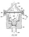
- Tissue that is larger than the pore size of the bottom face 2046b of the cup scaffold 2046 then collects in the area 2090 ( Fig. 30 ) formed between the plunger 2050 and the bottom face 2046b of the cup scaffold 2046 and continues to collect until, for example, the tissue reaches the insert 2050, thereby loading the cup scaffold 2046 with tissue in the area 2090.
- Any cut tissue that is smaller than the pore size of the bottom face 2046b of the cup scaffold 2046 and fluid pass through the cup scaffold 2046 and are aspirated through the outlet 2048 to a collection apparatus, not shown.
- the tissue will generally collect to a depth of up to about 4 mm.
- a spring 3047 that extends a length of the shaft portion 3045b, the distal portion 3046b of the post 3046, and a sleeve 3044.
- the spring 3047 facilitates axial movement of the sleeve 3044 within the shaft 3045b during coupling and removal of the cap 3041, as will be further described below.
- the sleeve 3044 includes a proximal end 3044b configured for engagement with the distal portion 3046b of the post 3046 and a distal end 3044a having tabs 3057 ( Fig. 37 ) and first and second arms 3058,3059 extending from the distal end 3044a.
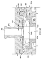
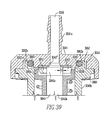
- Figs. 38 and 39 show the location of ramps 3052 that are coupled to the cap 3041. These ramps 3052 cover about 180° of rotation so that the scaffold 3043 is only in contact with the scaffold gasket 3042a over a small angle of rotation, as will be further described below. This substantially reduces the possibility of damage to the open face 3043"of the scaffold 3043 when the cap 3041 is inserted onto and removed from the shaft 3045b, as will be further described below.
- the sleeve 4044 includes a proximal end 4044b configured for engagement with the distal portion 4046b of the post 4046 and a distal end 4044a having tabs 4057 ( Fig. 43 ) and first and second arms 4058,4059 extending from the distal end 4044a. As shown in Figs. 43 and 45 , the arms 4058,4059 of the sleeve 4044 are housed within slots 4070 located in the housing 4045 such that an overlap is created between the arms 4058,4059 and the housing 4045.
- a tissue scaffold 4043 is located within an internal cavity 4044c of the sleeve 4044 such that a second region 4043b of the scaffold 4043 is contained within the sleeve 4043 and a first region 4043a extends from the distal end 4044a of the sleeve 4044.
- the distal portion 4046b of the post 4046 extends into the inner cavity 4044c of the sleeve 4044 to substantially reduce the possibility of the scaffold 4043 becoming lodged within the inner cavity 4044c of the sleeve 4044 during extraction of the scaffold 4043 from the sleeve 4044, as will be further described below. As shown in Figs.
- the outlet cap 48 can be permanently or removable coupled to the housing 42.
- the size of the one or more openings 45, 45a formed in inner tubular member 14 can be of any size to provide sufficient aspiration of fluid and cut tissue from the aspiration lumen 16.
- the tissue collection device 40 can contain various sizes and types of scaffold.
Landscapes
- Health & Medical Sciences (AREA)
- Life Sciences & Earth Sciences (AREA)
- Engineering & Computer Science (AREA)
- Biomedical Technology (AREA)
- Surgery (AREA)
- Heart & Thoracic Surgery (AREA)
- General Health & Medical Sciences (AREA)
- Veterinary Medicine (AREA)
- Animal Behavior & Ethology (AREA)
- Public Health (AREA)
- Nuclear Medicine, Radiotherapy & Molecular Imaging (AREA)
- Medical Informatics (AREA)
- Molecular Biology (AREA)
- Orthopedic Medicine & Surgery (AREA)
- Wood Science & Technology (AREA)
- Biotechnology (AREA)
- Bioinformatics & Cheminformatics (AREA)
- Genetics & Genomics (AREA)
- Zoology (AREA)
- Chemical & Material Sciences (AREA)
- Organic Chemistry (AREA)
- Hematology (AREA)
- Anesthesiology (AREA)
- Vascular Medicine (AREA)
- Dentistry (AREA)
- Oral & Maxillofacial Surgery (AREA)
- Transplantation (AREA)
- Cell Biology (AREA)
- General Engineering & Computer Science (AREA)
- Biochemistry (AREA)
- Microbiology (AREA)
- Rheumatology (AREA)
- Materials For Medical Uses (AREA)
- Surgical Instruments (AREA)
Abstract
Description
- The present disclosure relates to tissue harvesting.
- The tissue harvesting techniques described below can be used to repair, regenerate and/or augment tissue in a range of surgical or cosmetic applications.
- Trauma to the articular surface is a common injury in sports. The symptoms arising from such damage include pain, joint locking, instability, and stiffness, and the damage predisposes the cartilage and joint to wear and degeneration which can lead to osteoarthritis and the need for total knee replacement. For example, the tissue harvesting techniques can be used to treat focal and degenerative cartilage lesions before a total joint replacement is indicated and can postpone or obviate the need for a total joint replacement. Articular cartilage lines the ends of bones and facilitates frictionless movement of joints. Damage to the cartilage caused by injury or disease does not heal and the pathological changes resulting from this damage can be a source of great pain; limiting mobility and having a significant detrimental impact on the quality of life. Over time, lesions are likely to degenerate into osteoarthritis. Injury is not the only cause of osteoarthritis, with genetics, obesity, joint biomechanics, diet and age all playing a role.
- Known surgical techniques for treating damaged cartilage include lavage and debridement (joint is flushed with fluid and damaged tissue removed providing temporary symptom relief); microfracture (penetration of the subchondral bone to stimulate bleeding in to the cartilage lesion in an effort to promote a fibrocartilage healing response); periosteal grafts (autologous periosteum is grafted into the defect site and sutured or glued into place); mosaicplasty (plugs of cartilage and bone are harvested from low weight bearing regions of the joint and transplanted into the defect); and autologous chondrocyte implantation (ACI) (cells are isolated and expanded from a cartilage biopsy from a non-weight bearing location, and the cells are re-introduced into the defect in a second procedure approximately six weeks later either in suspension or on a scaffold (Matrix-guided ACI-MACI)).
- Trauma to the articular surface is a common injury in sports. The symptoms arising from such damage include pain, joint locking, instability, and stiffness, and the damage predisposes the cartilage and joint to wear and degeneration which can lead to osteoarthritis and the need for total knee replacement. The tissue harvesting techniques described below can be used to treat focal and degenerative cartilage lesions before a total joint replacement is indicated and can postpone or obviate the need for a total joint replacement. The techniques enable the surgical team to purify a unique population of repair cells from tissue from the patient, such as, for example, synovial/adipose tissue, and deliver the cells back into the patient's joint to stimulate a hyaline-like cartilage repair in a single surgical procedure. The repair cells are harvested arthroscopically from a site local to the defect (i.e. within the joint) and delivered directly onto a biocompatible scaffold, and in some implementations, onto particular regions of the scaffold, which is then implanted at the repair site.
- In implementations of the disclosure, the adipose tissue harvested is a fat pad or corpus adiposum, which is a localized accumulation of encapsulated adipose tissue. Fat pads can be found, for example in the cheek (corpus adiposum buccae) and also found within certain joints where they are referred to as the infrapatellar, navicular, olecranon, scaphoid, pronator quadratus, and preachilles fat pads. These pads may act as a cushion to absorb forces generated across the joint and also may help to distribute lubricants in the joint cavity.
- The infrapatellar fat pad, also referred to as Hoffa's pad and adipose synovium includes synovium and subsynovial adipose tissues and lies beneath the patella (kneecap) separating it from the femoral condyle. The infrapatellar fat pad varies in size and volume, but generally includes two large basal prominences lying on either side of the intrachondylar notch. In situations where forces are directed at the patella the infrapatllar fat pad acts as a shock absorber, protecting the underlying structures. During trauma the fat pad undergoes a number of changes, which include, without limitation, the fat pad volume increasing secondary to oedema and haemorrhage due to increased subsynovial vascularisation and the subsequent infiltration of the fat pad with macrophages.
- We have found that by harvesting a defined size fragment of fat pad tissue, comprising progenitor cells and reintroducing this fragment in combination with a biocompatible scaffold, such as a gel, into another site within the body, it is possible to generate tissue types that are different from the tissue fragment following exposure of the fragment to environmental factors.
- It is envisaged that the progenitor cells contained within the fragments of fat pad could be directed along, for instance, the osteogenic, adipogenic, chondrogenic, myogenic, neurogenic lineages giving rise to bone, cartilage, muscle or nerve tissue.
- Once fat pad fragments are implanted into the site, the fat pad fragments will gradually remodel thereby allowing the progenitor cells to migrate out of the fragment and integrate into the surrounding tissue, thereby allowing the progenitor cells to differentiate into the appropriate endogenous cell type(s).
- The fat pad tissue can be autogeneic tissue, allogeneic tissue, xenogeneic tissue and combinations thereof.
- The use of autogeneic tissue is particularly desirable as it substantially reduces the potential for an immunogenic host response and tissue rejection.
- If the autogenic fat pad is to be used, a specific consideration for the surgeon is how readily accessible the fat pad is during the primary surgical procedure. For example, if a surgeon is repairing a cartilage defect within the femoral plateau, then it would be appropriate to use the infrapatellar fat pad. This will minimise the incisions that the surgeon has to make and therefore improve the outcome and the welfare of patient.
- Using autologous tissue as a source for cartilage repair implants is often limited due to a number of problems including: availability, source, pain and enrichment. The infrapatellar fat pad is a joint tissue that is easily accessible to the orthopedic surgeon and is present in sufficient quantity to load a number of scaffolds for use in cartilage repair, particularly of focal defects. Furthermore the use of the infrapatellar fat pad substantially reduces the possibility of secondary site morbidity when compared to other tissue sources, such as bone marrow aspirations and substantially reduces the need to enrich the progenitor cells to show therapeutic effect.
-
US 2005059905 describes devices and methods for extracting and nacerating tissue, and optionally for depositing the tissue onto a tissue scaffold. - In one general aspect, the present, disclosure relates to a tissue collection apparatus , as claimed hereafter, comprising a housing defining an inlet and an outlet, and a tissue scaffold suitable for disposal within the housing, the tissue scaffold configured to be loaded with tissue under the application of an aspiration force applied through the tissue collection apparatus, and a sleeve disposed around the tissue scaffold, the sleeve configured to allow a tissue-containing fluid to flow through the tissue scaffold, wherein the tissue scaffold comprises a first region and a second region, the two regions having dissimilar mechanical and porosity properties. Preferred embodiments of the invention are set forth in the dependent claims. The sleeve is configured to allow the tissue-containing fluid to flow only through the first region of the tissue scaffold. The sleeve is configured to release the tissue scaffold upon application of a downward force applied to the sleeve. The sleeve is compliant and compresses around the tissue scaffold upon application of a force applied to the sleeve thereby allowing access to the tissue scaffold for removal from the sleeve. The apparatus further comprises a filter disposed within the housing of the tissue collection apparatus. The filter defines a set of openings having an opening size of up to about 600 µm to about 1mm, or of about 600 µm. The filter defines a plurality of openings having an opening size of about 2.4 mm, or of about 3 mm. The apparatus further comprises a set of fluid-flow pathways formed in the first region of the tissue scaffold, the pathways configured to permit flow of a tissue-containing fluid therethrough. One of the set of pathways comprises a diameter of about 500 µm and a second of the set of pathways comprises a diameter of about 300 µm. At least some of the pathways open as aperatures at a periphery of the scaffold to provide points of entry for the tissue containing fluid into the scaffold. The outlet is in fluid communication with an aspiration source.
- The tissue scaffold is cup-shaped. The apparatus further includes an insert, a portion of which is disposed within the tissue scaffold and is configured to limit the amount of tissue collected in the tissue scaffold. The insert is removably disposed within the tissue scaffold.
- The inlet of the housing may be associated with a surgical instrument including an elongate outer tubular member defining a distal opening, an elongate inner tubular member rotatably received within the outer tubular member and defining an aspiration lumen, the elongate inner tubular member including a distal cutter adjacent the distal opening in the elongate outer tubular member, and a tissue collection device in fluid communication with the aspiration lumen of the elongate inner tubular member, the tissue collection device for receiving a tissue scaffold configured to be loaded with tissue under the application of an aspiration force applied through the tissue collection device to the aspiration lumen of the elongate inner tubular member to aspirate tissue therethrough.
- A filter positioned between the elongate inner tubular member and the inlet of the housing. A hub is configured to receive a portion of the elongate outer tubular member and the inner tubular member. The hub includes a sidewall defining an aperture in fluid communication with the aspiration lumen of the elongate inner tubular member and the housing is configured to be coupled to the aperture such that the tissue scaffold is loaded with tissue during aspiration of the tissue from the aspiration lumen..
- The tissue collection apparatus is releasably coupled to the aperture such that the tissue scaffold is loaded with tissue during aspiration of the tissue from the aspiration lumen. The tissue collection device is permanently coupled to the aperture such that the tissue scaffold is loaded with tissue during aspiration of the tissue from the aspiration lumen. The inner tubular member further defines an opening in a proximal region of the inner tubular member that is in fluid communication with the aspiration lumen. The hub defines an opening extending in a direction substantially transverse to the longitudinal axis of the elongate inner tubular member and in fluid communication with the aspiration lumen of the inner tubular member. A tubing connector is disposed in the hub opening. A first tubing is coupled to and between the tubing connector and the filter, and a second tubing coupled to and between the filter and the collection device. The filter is disposed within the housing. The housing further includes a removably coupled inlet connector. The inlet connector is disposed in the hub opening. A spacing is between the filter and the inlet connector is in the range of 30 mm to 40 mm. The housing further includes a tubing connector coupled thereto. The filter includes openings formed therein having an opening size of about 50 µm to about 600 µm. The filter includes openings formed therein having an opening size of about 300 µm to about 600 µm. The apparatus further includes a vacuum source coupled to the surgical instrument that is effective to uniformly load the fluid permeable tissue scaffold with tissue. The apparatus further includes a fluid permeable tissue scaffold configured to be loaded with tissue cut by the surgical blade.
- In another general aspect, a method ,not claimed, includes aspirating a cut tissue through an aspiration lumen of a cutter and loading a tissue scaffold of a tissue collection device with cut tissue under the application of an aspiration force applied through the tissue collection device to the aspiration lumen of the cutter to aspirate tissue therethrough.
- Implementations can include one or more of the following features. For example, the method further comprises passing the cut tissue through a filter prior to the step of loading the tissue scaffold. The method further comprises removing the tissue scaffold from the tissue collection device. The cut tissue is synovial or adipose tissue. The loading step includes loading the tissue scaffold with cut tissue solely under the application of an aspiration force applied through the tissue collection device to the aspiration lumen of the cutter to aspirate tissue therethrough. Loading the tissue scaffold comprises loading a specific region of the tissue scaffold with the cut tissue. The tissue scaffold comprises a first phase and a second phase, and wherein only the first phase is loaded with the cut tissue. The method further comprises piercing the tissue scaffold to form a set of fluid-flow pathways in the tissue scaffold. Loading the tissue scaffold comprises loading the cut tissue into a first region, and not in another region, of the tissue scaffold. The tissue scaffold includes a first material forming a cartilage region and a second material forming a bone region of the tissue scaffold, and wherein the tissue fragments are loaded into the cartilage region. The tissue scaffold comprises an osteochondral plug. The tissue comprises synovium. The tissue comprises adipose.
- In another general aspect, a kit for harvesting tissue comprises an elongate outer tubular member defining a distal opening, an elongate inner tubular member adapted to be rotatably received within the elongate outer tubular member therein defining an aspiration lumen, the elongate inner tubular member including a distal cutter, which in use, is adjacent the distal opening in the elongate outer tubular member, and a tissue collection device, which in use, is in fluid communication with the aspiration lumen of the elongate inner tubular member, the tissue collection device for receiving a tissue scaffold configured to be loaded with tissue under the application of an aspiration force applied through the tissue collection device to the aspiration lumen of the elongate inner tubular member to aspirate tissue therethrough.
- Implementations can include one or more of the following features. For example, the kit further comprises the tissue scaffold, the scaffold being configured such that in use the scaffold is loaded with tissue under the application of an aspiration force applied through the tissue collection device to the aspiration lumen of the elongate inner tubular member to aspirate tissue therethrough. The kit further comprises a filter positioned between the elongate inner tubular member and the tissue collection device and in fluid communication with the aspiration lumen of the elongate-inner tubular member. The filter is disposed within the tissue collection device. The tissue scaffold is configured to be capable of being loaded solely under the application of the aspiration force applied through the tissue collection device to the aspiration lumen of the elongate inner tubular member to aspirate tissue therethrough.
- Advantages can include eliminating the risk of disease transmission and immune response associated with treatment using allograft; enabling cartilage repair procedures to be performed in focal lesions in older as well as young patients; minimizing damage to the donor site; isolating tissue fragments which are within a specific size range; minimizing intervention from the surgeon; and harvesting tissue, loading tissue onto a scaffold in an expedient manner, and implanting the scaffold for tissue repair in a sterile manner in a single surgical procedure.
- The details of one or more embodiments of the invention are set forth in the accompanying drawings and the description below. Other features, objects, and advantages of the invention will be apparent from the description and drawings, and from the claims.
-
-
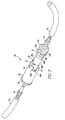
Fig. 1 is an illustration of a tissue harvesting assembly shown in use. -
Fig. 2 is a cross-section view of a tissue collection device of the assembly ofFig. 1 . -
Fig. 3 is an exploded, perspective view of the tissue collection device ofFig. 2 . -
Fig. 4 is a side perspective view of surgical blade hub of the assembly ofFig. 1 . -
Fig. 5 is a cross-section view of the hub ofFig. 4 . -
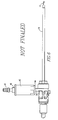
Fig. 6 is a side perspective view of an alternative tissue harvesting assembly. -
Fig. 7 is a cross-section view of the blade ofFig. 6 . -
Fig. 8 illustrates removal of a tissue scaffold from the tissue collection device ofFig. 2 . -
Figs. 9A-9B illustrate delivery and implementation of the tissue scaffold ofFig. 8 . -
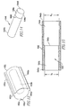
Fig. 10 is a side perspective view of an alternative tissue collection device. -
Fig. 11 is a perspective view of the alternative tissue collection device ofFig. 10 . -
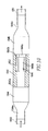
Fig. 12 is a cross-section view of the tissue collective device ofFig. 11 . -
Fig. 13 is a perspective view of the sleeve of the tissue collection device ofFigs. 10-12 . -
Fig. 14 is a perspective view of a tissue scaffold for use with the tissue collection device ofFigs. 10-12 . -
Fig. 15 is a cross-section view of the housing ofFigs. 10-12 . -
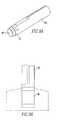
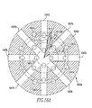
Fig. 16A is a front end view of an alternative implementation of the first region of the tissue scaffold ofFig. 14 . -
Fig. 16B is a front end view of an alternative implementation of the first region of the tissue scaffold ofFig. 14 . -
Fig. 16C is a front end view of an alternative implementation of the first region of the tissue scaffold ofFig. 14 . -
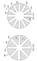
Fig. 16D is a front end view of an alternative implementation of the first region of the tissue scaffold ofFig. 14 . -
Fig. 16E is a cross-section view of the first region of the tissue scaffold ofFig. 16D . -
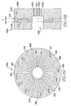
Fig. 16F is a front end view of an alternative implementation of the first region of the tissue scaffold ofFig. 14 . -
Fig. 16G is a cross-section view of the first region of the tissue scaffold ofFig. 16F . -
Fig. 16H is a front end view of an alternative implementation of the first region of the tissue scaffold ofFig. 14 . -
Fig. 16I is a cross-section view of the first region of the tissue scaffold ofFig. 16H . -
Fig. 16J is a front end view of an alternative implementation of the first region of the tissue scaffold ofFig. 14 . -
Fig. 16K is a cross-section view of the first region of the tissue scaffold ofFig. 16J . -
Fig. 17 is a perspective view of an alternative implementation of the tissue collection device ofFig. 11 . -
Fig. 18 is a perspective view of an alternative implementation of the tissue collection device ofFig. 11 . -
Fig. 19 is a perspective view of an alternative implementation of the tissue collection device ofFig. 11 . -
Figs. 20A-20C illustrate removal of a tissue scaffold from an implementation of the tissue collection device ofFig. 10 . -
Figs. 21A-21C illustrate removal of a tissue scaffold from an implementation of the tissue collection device ofFig. 10 . -
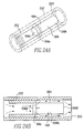
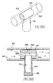
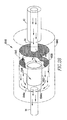
Figs. 22A-22B ,23A-23B ,24A-24B ,25 , and26A-26B illustrate alternative configurations for holding a tissue scaffold within a sleeve of the tissue collection device ofFig. 10 . -
Fig. 27 is a side perspective view of an alternative tissue harvesting assembly. -
Fig. 28 is a schematic view of the alternative tissue harvesting assembly ofFig. 27 . -
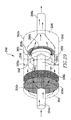
Fig. 29 is a perspective view of an alternative implementation of a tissue collection device. -
Fig. 30A is a perspective view of an alternative housing configuration of the tissue collection device ofFig. 29 . -
Fig. 30B is a cross-section view of an alternative housing configuration of the tissue collection device ofFig. 30 . -
Fig. 31 is a perspective view of an alternative insert for use with the housing ofFigs. 30A and30B . -
Fig. 32 is a cross-section view of a surgical site prepared to receive a tissue scaffold used in the implementation of the tissue collection device ofFig. 29 . -
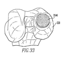
Fig. 33 is a perspective view of a cup scaffold positioned in the surgical site ofFig. 31 . -
Figs. 34A-34B are perspective views of alternative embodiments of the tissue collection apparatus of the present disclosure. -
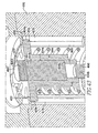
Fig. 35 is a cross-sectional view of the tissue collection apparatus ofFig. 34A . -
Fig. 36 is a cross-sectional view of the housing base portion and inlet connector of the tissue collection apparatus ofFig. 34A . -
Fig. 37 is a cross-sectional view of the housing shaft and outlet cap of the tissue collection apparatus ofFig. 34A . -
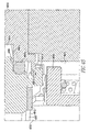
Fig. 38 is a cross-sectional view showing the overlap between the scaffold and scaffold gasket of the tissue collection apparatus ofFig. 34A . -
Fig. 39 is a cross-sectional view showing the outlet cap ramps of the tissue collection apparatus ofFig. 34A . -
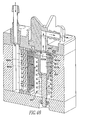
Fig. 40 is a perspective view illustrating the flow of tissue and fluid through the tissue collection apparatus ofFig. 34A . -
Figs. 41A-41D are perspective views illustrating use of the tissue collection apparatus ofFig. 34A . -
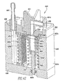
Fig. 42 is a cross-sectional view of the tissue collection apparatus ofFig. 34B . -
Fig. 43 is a cross-sectional view showing the scaffold and sleeve of the tissue collection apparatus ofFig. 34B . -
Fig. 44 is a cross-sectional view of the outlet cap and the second depression of the tissue collection apparatus ofFig. 34B . -
Fig. 45 is a cross-sectional view showing the overlap between the housing and the sleeve ann of the tissue clollection apparatus ofFig. 34B . -
Fig. 46 is a cross-sectional view illustrating the flow of tissue and fluid through the tissue collection apparatus ofFig. 34B . -
Figs. 47A-47D are perspective views illustrating use of the tissue collection apparatus ofFig. 34B . - Referring to
Fig. 1 , atissue harvesting assembly 100 includes asurgical blade 10 used to cut or resect bodily tissue T, such as synovial or adipose tissue, from a donor site, coupled to atissue collection device 40 for collecting cut tissue aspirated throughsurgical blade 10. Withintissue collection device 40 is atissue scaffold 46. Cut tissue under the application of the aspiration force applied through thetissue collection device 40 to thesurgical blade 10 loads substantially throughout, and not merely onto the surface of, thetissue scaffold 46. As discussed below, during the same surgical procedure, the tissue loadedscaffold 46 can be implanted at a cartilage tissue repair site. Preferably, the donor site and the repair site are within the same joint to minimize trauma to the patient and provide for a more expedient surgical procedure. -
Surgical blade 10 uses a tube-in-tube construction to shear tissue disposed between cutting edges of an elongate outer non-rotatingtubular member 12 and an elongate inner rotatingtubular member 14, as more fully explained inU.S. Patent No. 5,871,493 . Thesurgical blade 10 includes ahandpiece 20 coupled to themembers hub 22. The outertubular member 12 has a proximal end 12a fixed to thehub 22 and adistal end 12b defining anopening 15 forming a cutting port or window. Theinner tubular member 14 is rotatably received in the outertubular member 12 and has a distal end 14a with a cutting edge 17 (Fig. 6 ). Theinner tubular member 14 defines an aspiration lumen 16 (Fig. 5 ) communicating with thecutting edge 17 to remove cut tissue and fluid from a surgical site. When theblade 10 is assembled, thecutting edge 17 of theinner tubular member 14 is positioned adjacent theopening 15 of the outertubular member 12. - The
tissue collection device 40 is coupled to theblade 10 via aflexible tubing 50. Theflexible tubing 50 preferably includes afilter 30 positioned between theblade 10, and more particularly, the aspiration lumen 16 of thetubular member 14, and thetissue collection device 40 such that thefilter 30 is in fluid communication with the aspiration lumen 16 of theinner tubular member 14. In the implementation ofFig. 1 , filter 30 is coupled to aside port 24 of thehub 22 and to aninlet 44b of thetissue collection device 40 via thetubing 50. An exemplary filter for use with the implementations discussed herein is a 25 mm Delrin Filter Holder (Catalog No. 300-0001), available from VWR International Ltd. of Leicestershire, England, however, other known filters may be used.Filter 30 includes a screen (not shown) having openings formed therein each having an opening size of about 50 µm to about 1 mm, and in one particular implementation between about 50 µm to about 600 µm, so that only cut tissue sized in the range of less than about 50 µm to about 1 mm, and in the particular implementation between about 50 µm to about 600 µm, can pass through the filter to the tissue collection device. Such filtering assists to remove particles that are too large to efficiently load thetissue scaffold 46. - Referring to
Figs. 2 and3 , thetissue collection device 40 includes a substantiallycylindrical housing 42, aninlet connector 44, a biodegradable, fluid permeable, implant material, ortissue scaffold 46, and anoutlet cap 48. Rather than using aseparate filter 30 disposed along thetubing 50, in this implementation, afilter 32 is disposed directly within thehousing 42. - The
housing 42 includes a plurality of longitudinally extending and radially-projectingribs 42a formed about aninternal surface 42b of thehousing 42. Theribs 42a receive and releasably hold thetissue scaffold 46 within an interior 42c of thehousing 42 untiltissue scaffold 46 is removed from thehousing 42, as discussed below. Theribs 42a are dimensioned such that there is about 0.5 mm spacing between the inner surface of thehousing 42 and the outer surface 46c of thetissue scaffold 46 to allow for flow of the cut tissue and surgical fluid into thetissue collection device 40 so that the cut tissue may enter radially through the sides of thetissue scaffold 46 to load thetissue scaffold 46. Thehousing 42 also includes a plurality offlanges 43 formed about a periphery of anend 42d of thehousing 42. Theflanges 43 engage correspondingcutout portions 32a of thefilter 32 and cutout portions 44a of theinlet connector 44. When theflanges 43 are brought into engagement with theportions 32a and 44a to form thetissue collection device 40, there exists a spacing or gap D (Fig. 2 ) between thefilter 32 and theinlet connector 44 of between about 30 mm and 40 mm. Such spacing allows for effective removal of particles that are too large to efficiently loadtissue scaffold 46. - The
tissue scaffold 46 includes a first structure/material 46a forming a first region of the tissue scaffold bonded to a second structure/material 46b forming a second region of the tissue scaffold. The structure/material 46a has dissimilar mechanical and porosity properties from that ofmaterial 46b.Exemplary tissue scaffolds 46 that can be employed with the implementations discussed herein are described inU.S. Patent Nos. 6,013,853 ,5,876,452 , and5,607,474 . Anotherexemplary tissue scaffold 46 for use with the present implementations is the TruFit® BGS Plug, available from Smith & Nephew, Inc. of San Antonio, Texas. - Two
tubing connectors inlet connector 44 and theoutlet cap 48, respectively. Thetubing connector 47 couples thetubing 50 to thecollection device 40. Thetubing connector 49 couples atubing 52 to thecollection device 40 and to a source of vacuum 70 (Fig. 1 ), such as a vacuum pump or other suitable apparatus for providing aspiration during the surgical procedure. In addition, a collection apparatus (not shown) can be coupled to thetissue collection device 40 via thetubing 52 to collect tissue and fluid that passes through thetissue collection device 40. - Referring to
Figs. 4 and5 , the hub 22 (Fig. 1 ) of thesurgical blade 10 is coupled to the outertubular member 12 via anopening 41 formed in thehub 22. Theinner tubular member 14 is rotatably received within the outertubular member 12 and defines the aspiration lumen 16 extending longitudinally through theinner tubular member 14. Theinner tubular member 14 further defines one ormore openings 45 formed through aside wall 14b of themember 14 within the hub region of theblade 10, which are in fluid communication with the aspiration lumen 16 and achamber 26 defined withinhub 22.Hub 22 further includes aside port 24 formed through aside wall 28 ofhub 22 and in fluid communication with thechamber 26. Theside port 24 extends in a direction substantially transverse to the longitudinal axis L of theinner tubular member 14. Coupled to theside port 24 is atubing connector 29. Theside port 24 provides a pathway for fluid and cut tissue to flow from thesurgical blade 10 to thetissue collection device 40. - Referring to
Figs. 6 and7 , rather than coupling thetissue collection device 40 to thesurgical blade 10 via thetubing 50, thetissue collection device 40 can be directly attached to thesurgical blade 10 at theside port 24 via anextension 54. Theextension 54 can be removably or permanently coupled to theside port 24 of thehub 22. As illustrated inFigs. 6 and7 ,extension 54 is in fluid communication withchamber 26 and provides a pathway for cut tissue and surgical fluid to flow from thesurgical blade 10 to thetissue collection device 40. Specifically, cut tissue and surgical fluid flows through the aspiration lumen 16 and throughopening 45a of theinner tubular member 14. Theopening 45a defined in theside wall 14b of theinner tubular member 14 is sized to enable fragments of cut tissue that are within a size range that efficiently loads onto thetissue scaffold 46 to pass throughopening 45a. Theedges side wall 14b that form theopening 45a can further cut the tissue passing throughopening 45a to further reduce the size of the tissue fragments passing through theopening 45a. - In operation, the
surgical blade 10 is brought into contact with a desired bodily tissue, such as synovial or adipose tissue (Fig. 1 ). The operator cuts a desired amount of tissue from the donor site using theblade 10. Thevacuum source 70 aspirates fluid and the cut tissue through the aspiration lumen 16 of theinner tubular member 14 to thetissue collection device 40. The filter removes undesirable cut tissue from the fluid pathway, such as particles larger than, for example, about 300 µm to about 600 µm. The cut tissue and fluid then flow around and through thetissue scaffold 46 loading the scaffold with cut tissue for later implantation into the site to be treated. Any excess cut tissue and fluid volume pass through thetissue collection device 10 and are aspirated to the collection apparatus, not shown. - Referring to
Figs. 8 and9A-9B , to remove thetissue scaffold 46 from the tissuecollective device housing 42, the operator removes theoutlet cap 48 from thehousing 42, thereby exposing one end oftissue scaffold 46. The operator then contacts the exterior periphery oftissue scaffold 46 with a tissuescaffold delivery device 60, such as the TruFit® Delivery Device available from Smith & Nephew, Inc. of San Antonio, Texas. Once thetissue scaffold 46 is received by adistal end 61 of the tissue scaffold delivery device 60 (Fig. 9A ), the operator implants thetissue scaffold 46 at the desired location as shown inFig. 9B . Other implementations of delivering thetissue scaffold 46 to the desired location are described inU.S. Patent No. 6,013,853 . - An alternative implementation of a tissue collection device 1040 (
Fig. 10 ) for use with thetissue harvesting assembly 100 includes a cylindricaltransparent housing 1042 having afirst end 1042a and asecond end 1042b, a biodegradable, fluid permeable, implant material, ortissue scaffold 1046, and asleeve 1052 surrounding a portion, for example, the circumference but not ends, of thetissue scaffold 1046 and disposed between thetissue scaffold 1046 and thehousing 1042. Thehousing 1042 and thesleeve 1052 can be made from plastic or any other suitable material. Aninlet connector 1044 and anoutlet connector 1048 are removably coupled to the first andsecond ends housing 1042, using, for example, mating threaded connections (not shown) on theinlet connector 1044, and theoutlet connector 1048 and thehousing 1042, adhesive, an interference friction fit between the ends of thehousing 1042 and corresponding receiving portions (not shown) formed in theinlet connector 1044 and theoutlet connector 1048, or other suitable methods. Theconnectors housing 1042. Theinlet connector 1044 includes atubing connector portion 1044a that couples thetissue collection device 1040 to the blade 10 (Fig. 1 ) via aflexible tubing 1050. Theflexible tubing 1050 is coupled to a filter, such as thefilter 30 shown inFig. 1 , which is positioned between theblade 10 and thetissue collection device 1040 such that thefilter 30 is in fluid communication with theblade 10. Theoutlet connector 1048 includes atubing connector 1048a that couples thetissue collection device 1040 to atubing 1051 and to a source of vacuum 70 (Fig. 1 ). Fluid and cut tissue are aspirated through thetissue collection device 1040 to load thetissue scaffold 1046 with cut tissue as explained in more detail below. - Referring to
Figs. 11 ,12 , and15 , thehousing 1042 defines an interior 1043 including afirst portion 1043a having a diameter Da and asecond portion 1043b having a diameter Db, which is larger than diameter Da. Thefirst portion 1043a and thesecond portion 1043b intersect approximately mid-way along a length of thehousing 1042 to form a step orintersection 1043c. The sleeve 1052 (Figs. 11 ,12 , and13 ) includes a set of projectingribs 1052a disposed about the periphery of thesleeve 1052. Theribs 1052a are configured to permit thesleeve 1052 to be inserted into thesecond portion 1043b of thehousing 1042 and to be releasably held by thesecond portion 1043b by, for example, a friction fit between the wall of thehousing 1042 and theribs 1052a. As shown inFig. 12 , thesleeve 1052 slides into thesecond portion 1043b until anend 1052c of theribs 1052a abuts theintersection 1043c of thefirst portion 1043a and thesecond portion 1043b. Thesleeve 1052 further defines anopening 1052b dimensioned to receive thetissue scaffold 1046 as shown inFigs. 11 and12 . - The tissue scaffold 1046 (
Fig. 14 ) includes a first region ormaterial 1046a bonded (e.g., with adhesive) to a second region or material 1046b at anintersection 1046c. Thefirst region 1046a defines acircular face 1046d and includes aside portion 1046e. Theregions U.S. Patent Nos. 6,013,853 ,5,876,452 , and5,607,474 . Thetissue scaffold 1046 is longer than theopening 1052b of thesleeve 1052 such that when thetissue scaffold 1046 is inserted into theopening 1052b, thefirst region 1046a protrudes from thesleeve 1052. Theopening 1052b of thesleeve 1052 releasably holds thesecond region 1046b of thetissue scaffold 1046 via, for example, a frictional fit between thesecond region 1046b and the mating surfaces of theopening 1052b. As further illustrated inFig. 12 , one or more seals, such as o-ring 1054 placed between theoutlet connector 1048 and thehousing 1042, and/or thetissue scaffold 1046, provides a fluid-tight seal of thetissue collection device 1040. - In operation, the surgical blade 10 (
Fig. 1 ) is brought into contact with a desired bodily tissue, such as adipose or synovial tissue. The operator cuts a desired amount of tissue from the donor site using theblade 10. The vacuum source 70 (Fig. 1 ) aspirates the fluid and the cut tissue through the filter, which removes cut tissue that is larger than the opening size of the filter, from the fluid pathway, and to thetissue collection device 1040. The cut tissue and fluid enter theinterior 1043 of thehousing 1042 via theinlet connector 1044. The cut tissue and fluid flow over and around the exterior of thesleeve 1052 and enter theside 1046e of thefirst region 1046a of the tissue scaffold 1046 (as depicted by the arrows inFig. 12 ). Because thesleeve 1052 completely surrounds the exterior of thesecond region 1046b of thetissue scaffold 1046, and because the bonding agent (e.g., adhesive) between thefirst region 1046a and thesecond region 1046b of thetissue scaffold 1046 minimizes flow of tissue and fluid therethrough, the cut tissue and fluid flows through thefirst region 1046a of thetissue scaffold 1046. In particular, the tissue and fluid flow through theside 1046e of the first region 2046a and out of thecircular face 1046d (Fig. 12 ,14 ), thereby loading only thefirst region 1046a, including the interior and exterior of thefirst region 1046a, with cut tissue for later implantation into the desired site to be treated. By flowing cut tissue through theside 1046e of thefirst region 1046a and out of thecircular face 1046d, collection of excess debris on thecircular face 1046d is also minimized. Any excess debris may act as an abrasive possibly causing further damage to the cartilage. In addition, there is a small amount of clearance between the plug and the tissue, therefore any excess debris on the plug may cause problems with inserting it into a cartilage defect. Any excess cut tissue and fluid pass through theoutlet connector 1048 and are aspirated to a collection apparatus, not shown. - Referring to
Figs. 16A-16K , anexemplary tissue scaffold 1046 is shown that includes afirst region 1046a that includes one or more fluid-flow pathways 1047b formed through theside 1046e and one or more fluid-flow pathways 1047a formed through theface 1046d of thefirst region 1046a by passing a needle or other suitable device through thefirst region 1046a. The fluid-flow pathways first region 1046a of thetissue scaffold 1046. Thefirst region 1046a includes a cut out portion 1048 (Fig. 16E ), which is sized to receive amating protrusion 1080 of thesecond region 1046b of thetissue scaffold 1046 in a sliding frictional fit. - The
first region 1046 also includes one or morefluid flow pathways 1047a (Figs. 16A-16K ), for example, twentyfluid flow pathways 1047a (Fig. 16A ), by passing a needle through theface 1046d of thefirst region 1046a at desired locations (Fig. 16A ). Other methods of making the pathways, known to one of skill in the art, may also be used. As shown inFigs. 16E ,16G ,16I , and16K , thefluid flow pathways 1047a extend approximately halfway through thefirst region 1046a from theface 1046d, and have a length of about 10mm. Thefluid flow pathways 1047a have a cross-sectional diameter of about 300 µm. -
Figs. 16A-16K illustrate a number of possible configurations for forming thefluid flow pathways 1047b through theside 1046e of thefirst region 1046a. For example, as shown inFigs 16B and 16C , thefirst region 1046a includes four and sixfluid flow pathways 1047b, respectively, formed through thefirst region 1046a. Thefluid flow pathways 1047b extend across the full diameter of thefirst region 1046a and form eight (Fig. 16B ) and twelve (Fig. 16C )apertures 1049 around the periphery of theside 1046e. Theapertures 1049 provide entry points for the cut tissue to flow into the interior of thefirst region 1046a. -
Figs. 16D-16E illustrate fourfluid flow pathways 1047b formed through theside 1046e of thefirst region 1046a. Thefluid flow pathways 1047b do not extend across the full diameter of thefirst region 1046a. Thus, only fourapertures 1049 are formed in theside 1046e. As illustrated inFig. 16E , thefluid flow pathways 1047b are formed at approximately the mid-point of theside 1046e of thefirst region 1046a, and intersect at apoint 1056 near the center of thefirst region 1046a.Figs. 16F-16G illustrate afirst region 1046a having six fluid-flow pathways 1047b, which do not extend across the full diameter of thefirst region 1046a, with sixapertures 1049 formed in theside 1046e. - The
first region 1046a can include two layers of fluid-flow pathways, 1047b, 1047c (Figs. 16H-16K ), formed through theside 1046e of thefirst region 1046a and separated by a distance X along theside 1046e. For example, as shown inFigs. 16H-16I , thefirst region 1046a includes two layers of four fluid-flow pathways side 1046e of thefirst region 1046a and defining eightapertures 1049.Figs. 16J-16K illustrate afirst region 1046a including two layers of six fluid-flow pathways side 1046e of thefirst region 1046a and defining 12apertures 1049 in theside 1046e of thefirst region 1046a. Employing multiple layers of fluid-flow pathways, 1047b, 1047c in thefirst region 1046a increases the number of available apertures for the cut tissue to flow into thefirst region 1046a and also increases the number of pathways available for retaining the cut tissue within thefirst region 1046a. This results in more efficient loading of the tissue scaffold and provides for a faster overall process time. - In the examples shown in
Figs. 16A-16K , the fluid-flow pathways 1047a have a cross-sectional diameter of about 300 µm, and the fluid-flow pathways flow pathways flow pathways 1047a, b, c tend to increase the flow rate of the fluid and cut tissue through the interior of thefirst region 1046a and tend to trap the desired cut tissue within the interior of thefirst region 1046a, providing for more efficient loading of the tissue onto thetissue scaffold 1046, and specifically, onto thefirst region 1046a. -
Figs. 17-19 illustrate alternative configurations of thetissue collection device 1040, which, rather than employing a separate filter outside of thehousing 1042, such as filter 30 (Fig. 1 ), employ one or more filters within thehousing 1042. In particular, thetissue collection device 1040 ofFig. 17 includes asingle filter 1030 disposed within thehousing 1042, and thetissue collection device 1040 ofFig. 18 includes a set offilters first filter 1030a has a set of openings having an opening size of between about 600 µm to about 3 mm. Thesecond filter 1030b has a set of openings having an opening size of between about 600 µm to about 1 mm. The first filter catches the larger tissue particles first and allows the more moderate size tissue particles to be caught by the second filter. If there is only one filter, the larger tissue particles tend to clog the filter rather quickly. The tissue collection device ofFig. 19 includes acylindrical filter 1030c disposed within thehousing 1042 and surrounding thesleeve 1052 and thetissue scaffold 1046. Thecylindrical filter 1030c includes a set of protrudingribs 1031 configured to releasably hold, via, for example, a frictional fit, thefilter 1030c within thehousing 1042. - Each of the
filters Fig. 17 and the dual-filter configuration ofFig. 18 , the diameter of thehousing 1042 of thetissue collection device 1040 ofFig. 18 is approximately one half of the diameter of thehousing 1042 of thetissue collection device 1040 ofFig. 17 . An evensmaller housing 1042 may be realized by employing thecylindrical filter 1030c ofFig. 19 because the area of thefilter 1030c is relatively large relative to its size. Accordingly, employingmultiple filters cylindrical filter 1030c allows for asmaller housing 1042, when compared to, for example, atissue collection device 1040 employing afilter 30 disposed outside of thehousing 1042 or asingle filter 1030 disposed within the housing 1042 (Fig. 17 ). Such configurations may be appropriate for certain uses of thetissue collection device 1040, for example, where space is limited. For example, with regards to the implementation shown inFig. 7 , it is preferred that the device be small so as to be less cumbersome to the surgeon and not interfere with his/her ability to perform surgery. Also, with regards to the implementation shown inFig. 1 , the device may be clipped to the drape of the patient during surgery, therefore requiring the device to be smaller so that it does not interfere with other wires, clips, etc., in the surgical area and reducing the possibility of the device from falling off of the patient during movement, for example, of the patient's leg during surgery. -
Figs. 27 and28 illustrate an alternative implementation of thetissue collection device 1040 ofFig. 17 having thetissue collection device 1040 attached to a front end 22A of thehub 22. As illustrated inFig. 28 , in this implementation, cut tissue and fluid flow through theinner tubular member 14, as described above, and pass from theinner tubular member 14 and enter theinterior 1043 of the housing 1042 (as depicted by the arrows inFig. 28 ). The cut tissue and fluid flow through thefilter 1030, over and around the exterior of thesleeve 1052, and enter theside 1046e of thefirst region 1046a of the tissue scaffold 1046 (as depicted by the arrows inFig. 28 ). The cut tissue and fluid then flows through thefirst region 1046a and out of thecircular face 1046d and continues through theinner tubular member 14 where any excess tissue and fluid may be collected as described above. - Referring to
Figs. 10-12 and9A-9B , to remove thetissue scaffold 1046 from the tissuecollection device housing 1042, the operator removes theoutlet connector 1048 from thehousing 1042 to expose one end of thesleeve 1052 and thefirst region 1046a of thetissue scaffold 1046. The operator slidessleeve 1052 out of the open end of thehousing 1042, and contacts the exterior periphery of thefirst region 1046a of thetissue scaffold 1046 with a tissuescaffold delivery device 60, such as the TruFit® Delivery Device. Once thescaffold 1046 is received within thedistal end 61 of the tissue scaffold delivery device 60 (Fig. 9A ), the operator implants thetissue scaffold 1046 at the desired location as shown inFig. 9B . -
Figs. 20A-20C illustrate an alternative method of removing thetissue scaffold 1046 from anexemplary sleeve 2052 of the tissuecollection device housing 1042. As shown inFigs. 20A-b , thesleeve 2052 includes a seal orlip 2056 that forms a seal with ashaft 2058. Thesleeve 2052 is slidably coupled to theshaft 2058 such that when pressure is applied to thesleeve 2052 by a downward force F applied through the delivery device 60 (Fig. 20B ), theshaft 2058 passes through thelip 2056 of thesleeve 2052. As theshaft 2058 passes through thelip 2056, theshaft 2058 pushes thetissue scaffold 1046 out of the opposite end of thesleeve 2052 and into the receiving end of the delivery device 60 (Fig. 20B ). As thedelivery device 60 is pushed further against thesleeve 2052, thetissue scaffold 1046 is fully received by thedelivery device 60 and the operator can then implant thetissue scaffold 1046 at the desired location. -
Figs. 21A-21C illustrate a further alternative method of removing thetissue scaffold 1046 from anotherexemplary sleeve 2152 of the tissuecollection device housing 1042. As illustrated inFigs. 21A-b , thesleeve 2152 is made from a compliant material, such as rubber, nylon, or other suitable material, and includes aspring 2157. When pressure is applied to thesleeve 2152 by a downward force F applied through the delivery device 60 (Fig. 21B ), thesleeve 2152 and thespring 2157 compress downwardly and expose the exterior of thetissue scaffold 1046, which is captured within the delivery device 60 (Fig. 21B-c ). The operator can then implant thetissue scaffold 1046 at the desired location. - An alternative
tissue collection housing 2242 for use with thetissue collection device 1040 is shown inFigs. 22A-22B . Thehousing 2242 includes acylindrical sleeve 2252 for holding thetissue scaffold 1046 within thehousing 2242. Thecylindrical sleeve 2252 is configured to be slidably received within thehousing 2242 and held in place within a desired location within thehousing 2242 by a frictional fit. Thesleeve 2252 surrounds the entire exterior of thefirst region 1046a andsecond region 1046b of thetissue scaffold 1046 except for theface 1046d of thefirst region 1046a and theface 1046f of thesecond region 1046b, which are exposed to theinterior 2243 of thehousing 2242. In operation, as the cut tissue and fluid are aspirated through thetissue collection device 1040, the tissue and the fluid enter thescaffold 1046 through theface 1046d, travel substantially axially through thefirst region 1046a and thesecond region 1046b, and any tissue that is not captured by thetissue scaffold 1046, exits along with the fluid through theface 1046f (as illustrated by the arrows inFig. 22B ). -
Figs. 23A-23B illustrate an alternative configuration for placement of thetissue scaffold 1046 within thesleeve 2252. In this example, thesleeve 2252 surrounds the entiresecond region 1046b of thetissue scaffold 1046 but leaves thefirst region 1046a, including theface 1046d and theside portion 1046e, and theface 1046f of thesecond region 1046b, exposed to theinterior 2243 of thehousing 2242. As the cut tissue and fluid are aspirated through thetissue collection device 1040, the tissue and the fluid enter thescaffold 1046 through theface 1046d and theside portion 1046e of thefirst portion 1046a, travel through thefirst region 1046a and thesecond region 1046b, and any tissue that is not captured by thetissue scaffold 1046, exits along with the fluid through theface 1046f (as illustrated by the arrows inFig. 23B ). By allowing thefirst region 1046b to project from thesleeve 2252, the surface area of thefirst region 1046a is increased by about 240%, which leads to a higher population of tissue in thefirst region 1046a. This also provides a shorter flow path for the tissue fragments which leads to an increased flow rate and reduced overall procedure time. -
Figs. 24A-24B illustrate another alternative configuration for placement of thetissue scaffold 1046 within thesleeve 2252. Thesleeve 2252 surrounds the entirefirst region 1046a of thetissue scaffold 1046 but leaves thesecond region 1046b, including theface 1046f and aside portion 1064 exposed to theinterior 2243 of thehousing 2242. As the cut tissue and fluid are aspirated through thetissue collection device 1040, the tissue and the fluid enter thescaffold 1046 through theface 1046d of thefirst portion 1046a, and because a negative pressure is applied to theface 1046f and theside portion 1064 of thesecond region 1046b, the fluid and tissue flow through these surfaces and leave minimal traces of tissue in thesecond region 1046b. As shown inFig. 24B , because of the negative pressure applied to thesecond region 1046b, a majority of the tissue and fluid flow out thesecond portion 1046b through theside portion 1064 immediately downstream of theintersection 1046c between thefirst region 1046a and thesecond region 1046b, resulting in a minimized flow path of tissue and fluid through thetissue scaffold 1046. -
Fig. 25 illustrates a configuration wherein a set of pathways orpiercings 1070 are formed in thefirst region 1046a of thetissue scaffold 1046 by, for example, piercing thefirst region 1046a with a needle or other suitable instrument. Thepathways 1070 extend from theface 1046d of thefirst region 1046a to a desired location (e.g., to a point just prior to theintersection 1046c of thefirst region 1046a and thesecond region 1046b). As the cut tissue and fluid are aspirated through thetissue collection device 1040, the tissue and the fluid enter thescaffold 1046 through theface 1046d, travel substantially axially through thefirst region 1046a and thesecond region 1046b, and any tissue that is not captured by thetissue scaffold 1046, exits along with the fluid through theface 1046f. Thepathways 1070 allow for deep penetration of the tissue fragments along a desired path through thefirst region 1046a. This configuration provides a degree of controlled tissue loading to thetissue collection device 1040. As an alternative to forming a set ofpathways 1070 in thefirst region 1046a, a set of tissue-containing needles (not shown) can be used to provide for controlled distribution of the tissue fragments into thefirst regions 1046a. The needles (not shown) pierce thefirst region 1046a, inject the tissue into the desired locations within thefirst region 1046a, and are retracted from thetissue scaffold 1046 following injection. - A further alternative
tissue collection housing 2642 for use with thetissue collection device 1040 is shown inFigs. 26A-26B . Thecylindrical sleeve 2652 defines a rectangular, venturi-shaped fluid-flow passageway 2652a. Thetissue scaffold 1046 is positioned transverse to the flow of the cut tissue and the fluid through theinterior 2643 of thetissue collection housing 2642. In addition to thesleeve 2652, thehousing 2642 includes acylindrical tube 1080 that receives and surrounds thesecond region 1046b of the tissue scaffold, and is positioned with respect to thesleeve 2652 to provide a compression force on thetissue scaffold 1046 such that theface 1046d of thefirst region 1046a is sealed against thesleeve 2652 as shown inFig. 26B . Accordingly, only theside portion 1046e of thefirst region 1046a is exposed to the flow of tissue and fluid through theinterior 2643 of thehousing 2642. As the cut tissue and fluid are aspirated through thetissue collection device 1040, the tissue and the fluid enter thescaffold 1046 through theface side portion 1046e of thefirst portion 1046a, travel exclusively through thefirst region 1046a, and any tissue that is not captured in thefirst region 1046a, exits along with the fluid through the opposingside portion 1046e (as illustrated by the arrows inFig. 26B ). This provides a shorter flow path for the tissue fragments which leads to an increased flow rate and reduced overall procedure time. - An alternative implementation of a tissue collection device 2040 (
Fig. 29 ) for use with thetissue harvesting assembly 100 includes ahousing 2042 having afirst end 2042a and asecond end 2042b. Thehousing 2042 defines a substantially cylindrical cut outportion 2055 that further defines ashoulder 2055a. Theportion 2055 receives a biodegradable, fluid permeable, implant material, ortissue scaffold 2046, configured in the form of a cup. Thecup scaffold 2046 is received in theportion 2055 such that fluid and cut tissue flow substantially through an open interior 2046a of thecup scaffold 2046 and through abottom face 2046b of thecup scaffold 2046 as depicted by the arrows inFig. 29 .Cup scaffold 2046, and in particular thebottom face 2046b of thecup scaffold 2046 includes openings sized in the range of about 500 µm to about 1 mm to capture particles of a desired size for later implantation into a surgical site. The first andsecond ends housing 2042 are releasably coupled to each other using any suitable means, such as adhesives, screws, or by clamping the two ends 2042a and 2042b together, which facilitates removal of thecup scaffold 2046 from thehousing 2042 as will be explained in more detail below. - Removably coupled to the first and
second ends housing 2042, are aninlet connector 2044 and anoutlet connector 2048. Theconnectors second ends inlet connector 2044, theoutlet connector 2048, and thehousing 2042; adhesive; an interference friction fit between the ends of thehousing 2042 and corresponding receiving portions (not shown) formed in theinlet connector 2044 and theoutlet connector 2048; or other suitable methods. Theconnectors housing 2042. Theinlet connector 2044 includes atubing connector portion 2044a that couples thetissue collection device 2040 to the blade 10 (Fig. 1 ) via a flexible tubing (not shown). Theoutlet connector 2048 includes atubing connector 2048a that couples thetissue collection device 2040 to a tubing (not shown) and to a source of vacuum 70 (Fig. 1 ). Fluid and cut tissue are aspirated through thetissue collection device 2040 to load thecup scaffold 2046 with cut tissue as explained in more detail below. - Disposed within the
housing 2042 are a set offilters first filter 2030a has openings sized between, e.g., about 600 µm to about 3 mm, and in a particular implementation, the opening size is about 2.4 mm. Thesecond filter 2030b has openings sized between, e.g., about 600 µm to about 1 mm, and in a particular implementation, the opening size is about 0.6 mm. - The
cup scaffold 2046 includes anannular lip 2047 that cooperates with theshoulder 2055a of theportion 2055 of thehousing 2042 to maintain thecup scaffold 2046 in position relative to thehousing 2042 and to assist with removal of thecup scaffold 2046 from thehousing 2042 as will be described in more detail below. Alternatively, thecup scaffold 2046 may be formed without thelip 2047. Attached to one side of thesecond filter 2030b is an insert orplunger 2050 including a disc-shapedportion 2050b and acylindrical rod 2050a extending therefrom. As schematically depicted inFig. 29 ,insert 2050 may be attached to thesecond filter 2030b by screwing a threaded end (2051) of therod 2050a into a mating hole (not shown) in thefilter 2030b, gluing therod 2050a to thefilter 2030b, molding theinsert 2050 androd 2050a as part of thesecond filter 2030b, or by other suitable means. Theinsert 2050 is configured to limit the amount of buildup of tissue within thecup scaffold 2046. - In an alternative implementation illustrated in
Figs. 30A and30B , atissue collection device 2040a includes ahousing 3042 having afirst housing portion 2043 and asecond housing portion 2045 coupled together usingconnectors 3000, such as bolts, screws, clamps, or any other suitable means. Disposed between thefirst housing portion 2043 and thesecond housing portion 2045 is aseal member 2060, such as an o-ring, gasket, or other sealant, to provide a fluid-tight seal between thehousing portions second housing portions single filter 2070 that has a set of openings sized between about 0.6 mm to about 2.4mm, and in a particular implementation has a set of openings sized about 0.6 mm. - The
housing 3042 further includes aflow diverter 2080 disposed in thehousing 3042 between thefilter 2070 and thecup scaffold 2046. Thediverter 2080 includes a generally taperedinternal lumen 2080a for directing flow of fluid and tissue from thefilter 2070 into thecup scaffold 2046 as depicted by the arrows inFig. 30A and30B . As further illustrated inFig. 30A , aninsert 3050 includes arod 3050a and a disc-shapedmember 3050b disposed between thediverter 2080 and theannular lip 2047 of thecup scaffold 2046. The disc-shapedmember 3050b maintains the position of theinsert 3050 relative to thecup scaffold 2046 when thehousing 3042 is assembled and assists in removing theinsert 3050 from thecup scaffold 2046 as will be discussed in more detail below. - An alternative insert 4050 (
Fig. 31 ) may be employed with, for example, thehousing 3042 ofFigs. 30A and30B . As shown inFig. 31 , theinsert 4050 includes a disc-shapedmember 4050b and a cup-shapedportion 4050c having aclosed end 4050a extending from the disc-shapedmember 4050b. The cup-shapedportion 4050c is configured in substantially the same shape as thecup scaffold 2046 and is configured to fit within the open interior of thecup scaffold 2046. The cup-shapedportion 4050c includesopenings 4050d which permit fluid and cut tissue to flow through theportion 4050c and thereafter through thecup scaffold 2046 during use of the assembledhousing 2042. Theinsert 4050 acts to limit the amount of tissue buildup in thecup scaffold 2046. - In operation, the surgical blade 10 (
Fig. 1 ) is brought into contact with a desired bodily tissue, such as adipose or synovial tissue. The operator cuts a desired amount of tissue from the donor site using theblade 10. The vacuum source 70 (Fig. 1 ) aspirates the fluid and the cut tissue through, for example, thehousing 2042 such that the fluid and cut tissue enter through thehousing inlet 2044 and pass through either the twofilters Fig. 29 ) or through the single filter 2070 (Fig. 30 ), which remove cut tissue that is larger than the opening sizes of the filters, from the fluid pathway. The fluid and cut tissue are then directed into thecup scaffold 2046 where they flow betweeninsert 2050 and the inner wall of thecup scaffold 2046 as depicted by the arrows inFigs. 29 and30A . The spacing between theinsert 2050 and thecup scaffold 2046 is in the range of between about 1 mm to about 5 mm, and in certain implementations, is in the range of between about 2 mm to about 4 mm. - Tissue that is larger than the pore size of the
bottom face 2046b of thecup scaffold 2046 then collects in the area 2090 (Fig. 30 ) formed between theplunger 2050 and thebottom face 2046b of thecup scaffold 2046 and continues to collect until, for example, the tissue reaches theinsert 2050, thereby loading thecup scaffold 2046 with tissue in thearea 2090. Any cut tissue that is smaller than the pore size of thebottom face 2046b of thecup scaffold 2046 and fluid pass through thecup scaffold 2046 and are aspirated through theoutlet 2048 to a collection apparatus, not shown. Depending on the type of procedure and the type of tissue, the tissue will generally collect to a depth of up to about 4 mm. Once a desired amount of tissue is collected in thearea 2090, thehousing 2042 may be opened and theinsert 2050 removed from thecup scaffold 2046 by removing thefilters 2030b from the housing 2042 (Fig. 29 ) or by grasping themember 2050b and removing theinsert 2050 from the cup scaffold 2046 (Fig. 30A ). Once theinsert 2050 is removed from thecup scaffold 2046, the operator then removes thecup scaffold 2046 from thehousing 2042 and implants thecup scaffold 2046 into a surgical site 320 (as depicted inFig. 33 ) that has been prepared to receive thecup scaffold 2046, such as the surgical site depicted inFig. 32 . - As shown in
Fig. 32 , use of thecup scaffold 2046 provides a significant decrease in the amount of bone removal required for placement of the tissue scaffold into the surgical site. For example, instead of removing a cylindrical portion of bone for implantation of plug-type tissue scaffolds, such as scaffold 46 (Fig. 9B ), thecup scaffold 2046 only requires removal of a smallannular groove 325 from thesurgical site 320, which can result in as much as a 90% reduction in bone loss. - In addition to being used in conjunction with the surgical blade assemblies described above, each of the
tissue collection devices tissue collection devices -
Figs. 34A-34B illustrate two alternative embodiments of the tissue collection apparatus.Fig. 34A , shows a "cylinder"design 3040 and is further described below inFigs. 35-41 , whileFig. 34B shows a "tub"design 4040 and is further described below inFigs. 42-47 . Other designs or shapes for the tissue collection apparatus are within the scope of this disclosure. -
Figure 35 is a cross section of thetissue collection apparatus 3040 shown inFig. 34A . Theapparatus 3040 includes ahousing 3045 having abase portion 3045a, including aproximal end 3053 and adistal end 3054, and ashaft portion 3045b, including adistal end 3055 and aproximal end 3056, extending from thedistal end 3054 of thebase portion 3045a, anoutlet cap 3041, including anoutlet 3041a, coupled to thedistal end 3055 ofshaft portion 3045b, and aninlet connector 3048, including aninlet 3048a, coupled to theproximal end 3053 of thebase portion 3045a. A set offilters base portion 3045a of thehousing 3045. Thefilters base portion 3045a via an adhesive, interference friction fit, or other suitable method. When there is a set of filters, thefirst filter 3049a has a set of openings having an opening size of between about 600 µm to about 3 mm. Thesecond filter 3049b has a set of openings having an opening size of between about 600 µm to about 1 mm. Thefirst filter 3049a catches the larger tissue particles first and allows the more moderate size tissue particles to be caught by thesecond filter 3049b. If there is only one filter, the larger tissue particles may tend to clog the filter more quickly. The flow of tissue through theapparatus 3040 will be further described below. - Located between the
shaft portion 3045b and thebase portion 3045a is arim 3051. Therim 3051 includesopenings 3051a and serves to separate components of the shaft, specifically thespring 3047, from thefilters base portion 3045a also includes a throughhole 3052. Apost 3046, having a radially extendingproximal portion 3046a and adistal portion 3046b, is housed within the throughhole 3052. Theproximal portion 3046a is located within thebase portion 3045a and thedistal portion 3046b is located within theshaft portion 3045b. The purpose of thepost 3046 is further described below. Theproximal end 3053 of thebase portion 3045a is coupled to theinlet connector 3048 by press-fitting theend 3053 to thebase portion 3045a and additionally via the use of afixation device 3070, such as an Allen screw or other type of fixation device. Other methods of coupling are within the scope of this disclosure. In addition, agasket 3042b, as shown more clearly inFigs. 36 &37 , is located between thebase portion 3045a and theinlet connector 3048 to create a fluid seal between thebase portion 3045a and theinlet connector 3048 and to substantially reduce any axial tolerances on thefilters - Located within the
shaft portion 3045b is aspring 3047 that extends a length of theshaft portion 3045b, thedistal portion 3046b of thepost 3046, and asleeve 3044. Thespring 3047 facilitates axial movement of thesleeve 3044 within theshaft 3045b during coupling and removal of thecap 3041, as will be further described below. Thesleeve 3044 includes aproximal end 3044b configured for engagement with thedistal portion 3046b of thepost 3046 and a distal end 3044a having tabs 3057 (Fig. 37 ) and first andsecond arms sleeve 3044 is located in theshaft portion 3045b such thatsurfaces 3058a,3059a of thearms housing 3045. Atissue scaffold 3043, as described above, is located within aninternal cavity 3044c of thesleeve 3044 such that asecond region 3043b of thescaffold 3043 is contained within thesleeve 3044 and afirst region 3043a extends from the distal end 3044a of thesleeve 3044. Thedistal portion 3046b of thepost 3046 extends into theinner cavity 3044c of thesleeve 3044 to substantially reduce the possibility of thescaffold 3043 becoming lodged within theinner cavity 3044c of thesleeve 3044 during extraction of thescaffold 3043 from thesleeve 3044, as will be further described below. As shown more clearly inFig. 37 , agap 3060 is located between thedistal end 3046b of thepost 3046 and thescaffold 3043. Thegap 3060 allows for axial movement of thesleeve 3044 when theoutlet cap 3041 is rotated and removed from thehousing 3045, as will be further described below. - As shown more clearly in
Fig. 37 , thedistal end 3055 of theshaft 3045b includes a radially extendingedge portion 3061 and aprotrusion 3062 located on asurface 3061 a of theedge portion 3061. Theoutlet cap 3041 includes afirst groove 3063 configured to engage theedge portion 3061 when theoutlet cap 3041 is coupled to theshaft 3045b and asecond groove 3064 configured to engage theprotrusion 3062 when theoutlet cap 3041 is coupled to theshaft 3045b. Theoutlet cap 3041 also includes an O-ring 3065 located within thesecond groove 3064. When theoutlet cap 3041 is engaged with thedistal end 3055 of theshaft 3045b, the O-ring 3065 is compressed radially between thecap 3041 and aninner wall 3062a of theprotrusion 3062, thereby providing the radial location of theoutlet cap 3041 on theshaft 3045. In this manner, as more clearly shown inFig. 38 , radial compression of the O-ring 3065 is greater on thecap 3041 than on theinner wall 3062a, thereby substantially increasing the possibility of the O-ring 3065 remaining coupled to thecap 3041 when thecap 3041 is removed, as will be further described below. The axial location of theoutlet cap 3041 on theshaft 3045 is set by "X", or the height of thefirst groove 3063. Retention features, other than an O-ring, are within the scope of this disclosure and may be used. - The
outlet 3041a includes a throughhole 3066 extending a length of theoutlet 3041a. Located between thecap 3041 and thehousing 3045 is ascaffold gasket 3042a. As shown inFig. 37 , thescaffold gasket 3042a includes a throughhole 3067, such that the throughhole 3067 of thegasket 3042a is aligned with the throughhole 3066 of theoutlet 3041a.Figure 37 , and especiallyFig. 38 , shows a radial overlap, represented by the distance "Y", which exists between thefirst region 3043a of thescaffold 3043 and thescaffold gasket 3042a. The overlap is large enough to substantially reduce thescaffold 3042a from extending through the throughhole 3067, yet small enough to substantially reduce blocking of the pores in thesecond region 3043b of thescaffold 3043. In terms of size, the overlap remains the same independent of the diameter of thescaffold 3043, with the overlap covering up to about 10% of the diameter of thescaffold 3043. -
Figs. 38 and39 show the location oframps 3052 that are coupled to thecap 3041. Theseramps 3052 cover about 180° of rotation so that thescaffold 3043 is only in contact with thescaffold gasket 3042a over a small angle of rotation, as will be further described below. This substantially reduces the possibility of damage to theopen face 3043"of thescaffold 3043 when thecap 3041 is inserted onto and removed from theshaft 3045b, as will be further described below. - In operation, the surgical blade 10 (
Fig. 1 ) is brought into contact with a desired bodily tissue, such as adipose or synovial tissue. The operator cuts a desired amount of tissue from the donor site using theblade 10. The vacuum source 70 (Fig. 1 ) aspirates the fluid and the cut tissue through thefilters shaft portion 3045b. The cut tissue and fluid flow over and around the exterior of thesleeve 3044 and enter theside 3043a' of thefirst region 3043a of the tissue scaffold 3043 (as depicted by the arrows inFig. 40 ). Because thesleeve 3044 completely surrounds the exterior of thesecond region 3043b of thetissue scaffold 3043, and because the bonding agent (e.g., adhesive) between thefirst region 3043a and thesecond region 3043b of thetissue scaffold 3043 minimizes flow of tissue and fluid therethrough, the cut tissue and fluid flows through thefirst region 3043a of thetissue scaffold 3043. In particular, the tissue and fluid flow through the side 3043a'of thefirst region 3043a and out of thecircular face 3043" (Fig. 40 ), thereby loading only thefirst region 3043a, including the interior and exterior of thefirst region 3043a, with cut tissue for later implantation into the desired site to be treated. -
Figs. 41A-D illustrates the use of theapparatus 3040 by a surgeon. Thescaffold 3043 is pre-loaded under sterile conditions in a manufacturing facility withinsleeve 3044 such that a portion, at least part of the cartilage phase orfirst region 3043a, of thescaffold 3043 protrudes from thesleeve 3044. Prior to use of theapparatus 3040, thecap 3041 is coupled to theapparatus 3040, as shown inFig. 39 , such that theramps 3052 are not in contact with thearms 3058a,3059a of thesleeve 3044 and thescaffold 3043 is not under pressure by thegasket 3042a and thecap 3041. In anticipation of use ofapparatus 3040, the surgeon turns thecap 3041 clockwise about 45°, as shown by the arrow inFig. 41A , such that theramps 3052 engage arm 3059a, thereby facilitating movement of thesleeve 3044 within theshaft 3045b and an application of pressure on thescaffold 3043 bycap 3041 andgasket 3042b. In addition to theramps 3052, as described above, the O-ring applies pressure, via radial compression, to thewall 3062a to couple thecap 3041 to theshaft 3045b. Tubes, as described above and represented by arrows inFig. 41B , are coupled to theinlet 3048a on theinlet connector 3048 and theoutlet 3041 a on thecap 3041 and tissue is harvested, in the manner described above. - After the
scaffold 3043 has been loaded with tissue, thecap 3041 is removed by turning thecap 3041 anti-clockwise about 90°, as shown by the arrow inFig. 41C , such that theramps 3052 are disengaged from thesleeve 3044 and pressure is released from thescaffold 3043. A tissue scaffold delivery device 3070 (Fig. 41D ), as described above and shown inFig. 9A , is used to remove the tissue seeded-scaffold 3043 fromsleeve 3044 such that an end 3070a of thedevice 3070 is placed over thescaffold 3043 and downward pressure (3070c) is applied to thedevice 3070 to insert thescaffold 3043 into the end 3070a of thedevice 3070. While thedownward pressure 3070c is applied to thedevice 3070, movement of thesleeve 3044 occurs within theshaft 3045b, thereby substantially reducing thegap 3060 between thescaffold 3043 and thedistal end 3046b of the post and bringing theend 3046b into contact with thescaffold 3043 to further facilitate extraction of thescaffold 3043 from thesleeve 3044. Thedevice 3070 is then removed, as shown byarrow 3070b, and later used to implant thescaffold 3043 into a patient. -
Figure 42 is a cross section of thetissue collection apparatus 4040 shown inFig. 34B . Theapparatus 4040 includes ahousing 4045 having adistal end 4045a and aproximal end 4045b, atop portion 4060 coupled to thedistal end 4045a, and abase portion 4048 coupled to theproximal end 4045b. Thetop portion 4060 includes anoutlet cap 4041, having anoutlet 4041a, and aninlet 4049. Thehousing 4045 includes aninner cavity 4061. A set offilters inner cavity 4061 of thehousing 4045. Thefilters cavity 4061 via an adhesive, interference friction fit, or other suitable method. When there is a set of filters, thefirst filter 4049a has a set of openings having an opening size of between about 600 µm to about 3 mm. Thesecond filter 4049b has a set of openings having an opening size of between about 600 µm to about 1 mm. Thefirst filter 4049a catches the larger tissue particles first and allows the more moderate size tissue particles to be caught by thesecond filter 4049b. If there is only one filter, the larger tissue particles may tend to clog the filter more quickly. The flow of tissue through theapparatus 4040 will be further described below. - Also located within the
cavity 4061 is aspring 4047 that extends a length of thecavity 4061, apost 4046, and asleeve 4044. Thespring 4047 facilitates axial movement of thesleeve 4044 within thecavity 4061 during coupling and removal of thecap 4041, as will be further described below. Thepost 4046 is similar to thepost 3046 inapparatus 3040, such that thepost 4046 has a radially extendingproximal portion 4046a and adistal portion 4046b and is housed within a through hole 4062 in thebase portion 4048. Theproximal portion 4046a is located within thebase portion 3045a and thedistal portion 4046b is located within theinner cavity 4061 of thehousing 4045. Thesleeve 4044 includes aproximal end 4044b configured for engagement with thedistal portion 4046b of thepost 4046 and a distal end 4044a having tabs 4057 (Fig. 43 ) and first andsecond arms Figs. 43 and45 , thearms sleeve 4044 are housed withinslots 4070 located in thehousing 4045 such that an overlap is created between thearms housing 4045. This overlap substantially reduces the possibility of thesleeve 4044 from rotating and, in connection with theslots 4070, allows for axial movement of thesleeve 4044 during coupling and removal of thecap 4041 to theapparatus 4040, as will be further described below.. - A
tissue scaffold 4043, as described above, is located within aninternal cavity 4044c of thesleeve 4044 such that asecond region 4043b of thescaffold 4043 is contained within thesleeve 4043 and afirst region 4043a extends from the distal end 4044a of thesleeve 4044. Thedistal portion 4046b of thepost 4046 extends into theinner cavity 4044c of thesleeve 4044 to substantially reduce the possibility of thescaffold 4043 becoming lodged within theinner cavity 4044c of thesleeve 4044 during extraction of thescaffold 4043 from thesleeve 4044, as will be further described below. As shown inFigs. 42 and43 , agap 4080 is located between thedistal end 4046b of thepost 4046 and thescaffold 4043. Thegap 4080 allows for axial movement of thesleeve 4044 when theoutlet cap 4041 is rotated and removed from thehousing 4045, as will be further described below. - The
top portion 4060 includes afirst depression 4080 for receiving theinlet 4049 and asecond depression 4081 for receiving the outlet cap 4041 (Fig. 44 ). Thesecond depression 4081 includes afirst ledge 4081a, asecond ledge 4081 b, awall 4081c located between the first andsecond ledges opening 4081d. Theoutlet cap 4041 includes afirst portion 4041a having an area of reduceddiameter 4041a' and asecond portion 4041b, having radially extendingarms 4041b', extending from thefirst portion 4041a. Thefirst portion 4041 a also includes an O-ring 4090 coupled to the area of reduceddiameter 4041a'. Thecap 4041 is received within thesecond depression 4081 such that theradially extending arms 4041 b' are disposed within theopening 4081d and are engaged with thesecond ledge 4081 b, the O-ring 4090 is engaged with thewall 4081 c, and thefirst portion 4041a is engaged with thefirst ledge 4081 a. - When the
outlet cap 4041 is disposed within thesecond depression 4081, the O-ring 4090 is compressed radially between thecap 4041 and thewall 4081 c of thedepression 4080, thereby providing a fluid seal between thecap 4041 and thedepression 4080. In this manner, as shown inFigs. 44 and45 , radial compression of the O-ring 4090 is greater on thecap 4041 than on thewall 4081c, thereby substantially increasing the possibility of the O-ring 4090 remaining coupled to thecap 4041 when thecap 4041 is removed, as will be further described below. The axial location of theoutlet cap 4041 is set by Z", or the distance betweensurfaces 4041a", 4041b" on thefirst portion 4041a and theradially extending arms 4041b' of theoutlet cap 4041, respectively. Retention features, other than an O-ring, are within the scope of this disclosure and may be used. - Located between the
cap 4041 and thehousing 4045 is ascaffold gasket 4042. As shown inFigs. 42 and44 , thescaffold gasket 4042 includes a throughhole 4067, such that the throughhole 4067 of thegasket 4042 is aligned with the throughhole 4066 of theoutlet 4041a.Figs. 42 and46 show a radial overlap which exists between thefirst region 4043a of thescaffold 4043 and thescaffold gasket 4042. The overlap is large enough to substantially reduce thescaffold 4043 from extending through the throughhole 4067, yet small enough to substantially reduce blocking of the pores in thefirst region 4043a of thescaffold 4043. In terms of size, the overlap remains the same independent of the diameter of thescaffold 4043, with the overlap covering up to about 10% of the diameter of thescaffold 4043. -
Fig. 44 shows the location oframps 4052 that are coupled to thecap 4041. Theseramps 4052 cover almost 180° of rotation so that thescaffold 4043 is only in contact with thescaffold gasket 4042 over a small angle of rotation, as will be further described below. This substantially reduces the possibility of damage to theopen face 4043"of thescaffold 4043 when thecap 4041 is inserted onto and removed from theshaft 4045b, as will be further described below. - In operation, the surgical blade 10 (
Fig. 1 ) is brought into contact with a desired bodily tissue, such as adipose or synovial tissue. The operator cuts a desired amount of tissue from the donor site using theblade 10. The vacuum source 70 (Fig. 1 ) aspirates the fluid and the cut tissue through thefilters sleeve 4044 and enter theside 4043a' of thefirst region 4043a of the tissue scaffold 4043 (as depicted by the arrows inFig. 46 ). Because thesleeve 4044 completely surrounds the exterior of thesecond region 4043b of thetissue scaffold 4043, and because the bonding agent (e.g., adhesive) between thefirst region 4043a and thesecond region 4043b of thetissue scaffold 4043 minimizes flow of tissue and fluid therethrough, the cut tissue and fluid flows through thefirst region 4043a of thetissue scaffold 4043. In particular, the tissue and fluid flow through theside 4043a' of thefirst region 4043a and out of thecircular face 4043" (Fig. 46 ), thereby loading only thefirst region 4043a, including the interior and exterior of thefirst region 4043a, with cut tissue for later implantation into the desired site to be treated. -
Figs. 47A-D illustrate the use of theapparatus 4040 by a surgeon. Thescaffold 4043 is pre-loaded under sterile conditions in a manufacturing facility withinsleeve 4044 such that a portion, at least part of the cartilage phase orfirst region 4043a, of thescaffold 4043 protrudes from thesleeve 4044. Prior to use of theapparatus 4040, thecap 4041 is coupled to theapparatus 4040, such that theramps 4052 are not in contact with thearms sleeve 4044 and thescaffold 4043 is not under pressure by thegasket 4042 and thecap 4041. Rather, thearms Fig. 43 ) of thesecond depression 4081. In anticipation of use ofapparatus 4040, the surgeon turns thecap 4041 clockwise about 45°, as shown by the arrow inFig. 47A , such that theramps 4052 andarms 4041b'engage tabs 4057 andarms sleeve 4044 within thecavity 4061 and an application of pressure on thescaffold 4043 bycap 4041 andgasket 4042. In addition to theramps 4052 andarms 4041b', as described above, the O-ring 4090 applies pressure, via radial compression, to thewall 4081c to couple thecap 4041 to theapparatus 4040. Tubes, as described above and represented by arrows inFig. 47B , are coupled to theinlet 4049 and theoutlet 4041a on thecap 4041 and tissue is harvested, in the manner described above. - After the
scaffold 4043 has been loaded with tissue, thecap 4041 is removed by turning thecap 4041 anti-clockwise about 90°, as shown by the arrow inFig. 47C , such that theramps 4052 andarms 4041b' are disengaged from thesleeve 4044 and pressure is released from thescaffold 4043. A tissue scaffold delivery device 4070 (Fig. 47D ), as described above and shown inFig. 9A , is used to remove the tissue seeded-scaffold 4043 fromsleeve 4044 such that anend 4070a of thedevice 4070 is placed over thescaffold 4043 and downward pressure is applied to thedevice 4070 to insert thescaffold 4043 into theend 4070a of thedevice 4070. While the downward pressure is applied to thedevice 4070, movement of thesleeve 4044 occurs within thecavity 4061, thereby substantially reducing thegap 4060 between thescaffold 4043 and thedistal end 4046b of the post and bringing theend 4046b into contact with thescaffold 4043 to further facilitate extraction of thescaffold 4043 from thesleeve 4044. Thedevice 4070 is then removed and later used to implant thescaffold 4043 into a patient. - A number of implementations of the disclosure have been described. Nevertheless, it will be understood that various modifications may be made without departing from the spirit and scope of the disclosure. For example, although the
tissue scaffolds tissue collection apparatus material 46a orfirst region tissue collection apparatus tissue scaffolds material 46b orsecond region tissue scaffolds - Moreover, although the
tissue scaffold 46 has been described as being disposed in thehousing 42 such that there is about 0.5 mm spacing between the inner surface of thehousing 42 and the outer surface 46c of thetissue scaffold 46, thetissue scaffold 46 could be disposed with minimal spacing between thescaffold 46 and the inner surface ofhousing 42 such that cut tissue would load thescaffold 46 through the front face ofscaffold 46. - Rather than the tubing connector 29 (
Figs. 4 and5 ) being in communication with the aspiration lumen 16 of theinner tubular member 14 via thechamber 26, thetubing connector 29 could be directly coupled to theinner tubular member 14. Thetubing connector 29 can be coupled to theside port 24 using any suitable form of connection, including glue, weld, press fit, or, alternatively, thetubing connector 29 can be formed as one piece with thehub 22. In addition,tubing connectors inlet connector 44 and theoutlet cap 48, respectively, using any suitable form of connection, including glue, weld, press fit, or, alternatively, thetubing connectors inlet connector 44 and theoutlet cap 48, respectively. The tubing connectors described herein can be made from plastic, metal, or any other suitable materials. - The
extension 54 of theinlet connector 44 can be molded as one piece or separate from theinlet connector 44. If separate, theextension 54 can be coupled to theinlet connector 44 using glue, press-fit, weld, or another suitable connection method. In addition, theextension 54 of theinlet connector 44 can be molded as one piece with or separate from thehub 22. If separate, theextension 54 can be coupled to thehub 22 using glue, press-fit, weld, or another suitable connection method. - The
outlet cap 48 can be permanently or removable coupled to thehousing 42. The size of the one ormore openings tubular member 14 can be of any size to provide sufficient aspiration of fluid and cut tissue from the aspiration lumen 16. Thetissue collection device 40 can contain various sizes and types of scaffold. - In addition, although the tissue harvesting assembly has been described as including a
surgical blade 10 used to cut or resect bodily tissue, such as soft tissue, the tissue harvesting assembly can include an apparatus containing a curet or burr, for example, to removing bodily tissue, such as bone tissue. - Further, for each of the sleeve implementations described above (e.g.,
Figs. 11 ,12 ,20A-20C ,21A-21C ), thetissue scaffold 1046 can be removed from the sleeve without first removing the sleeve from thedelivery device housing 1042. - The components of the apparatuses shown in
Figs, 34-47 may include a metal or non-metal material and may be made via a molding process, such as injection molding, or other process known to one of skill in the art. In addition, thetop portion 4060 andbase portion 4048 may be coupled to thehousing 4045 via a press-fit or other type of coupling method. Similarly, theinlet 4049 may be coupled to thetop portion 4060 by a press-fit, adhesive, interference fit, or other type of coupling method known to one of skill in the art. - Accordingly, other embodiments are within the scope of the following claims.
Claims (40)
- A tissue collection apparatus (1040) comprising:a housing (1042) defining an inlet (1042a) and an outlet (1042b);a tissue scaffold (1046) suitable for disposal within the housing, the tissue scaffold configured to be loaded with tissue under the application of an aspiration force applied through the tissue collection apparatus , wherein the tissue scaffold comprises a first region (1046a) and a second region (1046b), wherein the two regions have dissimilar mechanical and porosity properties , characterised by the tissue collection apparatus (1040). comprises a sleeve (1052) disposed around the tissue scaffold (1046), the sleeve configured to allow a tissue-containing fluid to flow through the tissue scaffold.
- The apparatus of claim 1, wherein the sleeve is configured to allow the tissue-containing fluid to flow only through the first region of the tissue scaffold.
- The apparatus of claim 1, further comprising a set of fluid-flow pathways (1047a, 1047b) formed in the first region (1046a) of the tissue scaffold, the pathways configured to direct flow of a tissue-containing fluid therethrough.
- The apparatus of claim 3, wherein one of the set of pathways (1047a, 1047b) comprises a diameter of about 500 µm and a second of the set of pathways comprises a diameter of about 300 µm.
- The apparatus of claim 3, wherein at least some of the pathways open as apertures at the periphery of the scaffold to provide points of entry for the tissue containing fluid into the scaffold.
- The apparatus of claim 1 wherein the sleeve (1052) is configured to release the tissue scaffold (1046) upon application of a downward force applied to the sleeve.
- The apparatus of claim 1 wherein the sleeve is compliant and compresses around the tissue scaffold upon application of a force applied to the sleeve thereby allowing access to the tissue scaffold for removal from the sleeve.
- The apparatus of claim 1 wherein the tissue scaffold is cup-shaped (2046).
- The apparatus of claim 1 further comprising an insert (2050), a portion of which is disposed within the tissue scaffold and is configured to limit the amount of tissue collected in the tissue scaffold.
- The apparatus of claim 9, wherein the insert is removably disposed within the tissue scaffold
- The apparatus of claim 1, further comprising a filter (1030) disposed within the housing of the tissue collection apparatus.
- The apparatus of claim 11, wherein the filter (1030) defines a plurality of openings having an opening size of up to about 3mm.
- The apparatus of claim 12, wherein the filter (1030) defines a plurality of openings having an opening size of about 2.4mm.
- The apparatus of claim 12, wherein the filter (1030) defines a plurality of openings having an opening size of about 600 µm to about 1mm.
- The apparatus of claim 14, wherein the filter (1030) defines a pluarlity of openings having an opening size of about 600 µm.
- The apparatus of claim 1, wherein the outlet is in fluid communication with an aspiration source.
- An apparatus according to claim 1, wherein the inlet of the housing (42) can be associated with a surgical instrument, the surgical instrument comprising;
an elongate outer tubular member (12) defining a distal opening;
an elongate inner tubular member (14) rotatably received within the elongate outer tubular member (12) and defining an aspiration lumen (16), the elongate inner tubular member (14) including a distal cutter (17) adjacent the distal opening in the elongate outer tubular member;
wherein the inlet of the housing is in fluid communication with the aspiration lumen of the elongate inner tubular member, such that the tissue scaffold (46) is loaded with tissue under the application of an aspiration force applied through the housing to the aspiration lumen of the elongate inner tubular member to aspirate tissue therethrough. - The apparatus of claim 17, further comprising a filter (30) positioned between the elongate inner tubular member (14) and the inlet of the housing.
- The apparatus of claim 18, further comprising a hub (22) configured to receive a portion of the elongate outer tubular member (12) and the inner tubular member (14).
- The apparatus of claim 19, wherein the hub (22) includes a sidewall defining an aperture in fluid communication with the aspiration lumen of the elongate inner tubular member and wherein the housing (42) is configured to be coupled to this aperture such that the tissue scaffold (46) is loaded with tissue during aspiration of the tissue from the aspiration lumen.
- The apparatus of claim 20, wherein the housing is releasably coupled to the aperture such that the tissue scaffold is loaded with tissue during aspiration of the tissue from the aspiration lumen
- The apparatus of claim 20, wherein the housing is permanently coupled to the aperture such that the tissue scaffold is loaded with tissue during aspiration of the tissue from the aspiration lumen.
- The apparatus of claim 22, wherein the inner tubular member further defines an opening (45) in a proximal region of the inner tubular member that is in fluid communication with the aspiration lumpen.
- The apparatus of claim 22, wherein the hub defines an opening (41) extending in a direction substantially transverse to the longitudinal axis of the elongate inner tubular member and in fluid communication with the aspiration lumen of the inner tubular member.
- The apparatus of claim 24, further comprising a tubing connector (29) disposed in the hub opening.
- The apparatus of claim 25, further comprising a first tubing coupled to and between the tubing connector and the filter, and a second tubing coupled to and between the filter and the collection device.
- The apparatus of claim 26, wherein the filter is disposed within the housing.
- The apparatus of claim 27, wherein the housing further includes a removably coupled inlet connector (1044).
- The apparatus of claim 28, wherein the inlet connector is disposed in the hub opening.
- The apparatus of claim 29, wherein a spacing between the filter and the inlet connector is in the range of 30 mm to 40 mm.
- The apparatus of claim 26, wherein the housing further includes a tubing connector coupled thereto.
- The apparatus of claim 22, wherein the filter includes openings formed therein having an opening size of about 50 µm to about 600 µm.
- The apparatus of claim 32, wherein the filter includes openings formed therein having an opening size of about 300 µm to about 600 µm.
- The apparatus of claim 22, further comprising a vacuum source (70) coupled to the surgical instrument that is effective to uniformly load the fluid permeable tissue scaffold with tissue.
- The apparatus of claim 22, further comprising a fluid permeable tissue scaffold configured to be loaded with tissue cut by the surgical blade.
- A kit for harvesting tissue, comprising:an elongate outer tubular member defining a distal opening;an elongate inner tubular member adapted to be rotatably received within the elongate outer tubular member therein defining an aspiration lumen, the elongate inner tubular member including a distal cutter, which in use, is adjacent the distal opening in the elongate outer tubular member; anda tissue collection device, which in use, is in fluid communication with the aspiration lumen of the elongate inner tubular member, the tissue collection device for receiving a tissue scaffold configured to be loaded with tissue under the application of an aspiration force applied through the tissue collection device to the aspiration lumen of the elongate inner tubular member to aspirate tissue therethrough.
- The kit according to claim 36, the kit further comprising the tissue scaffold, the scaffold being configured such that in use the scaffold is loaded with tissue under the application of an aspiration force applied through the tissue collection device to the aspiration lumen of the elongate inner tubular member to aspirate tissue therethrough.
- The kit of claim 36, further comprising a filter positioned between the elongate inner tubular member and the tissue collection device and in fluid communication with the aspiration lumen of the elongate inner tubular member.
- The kit of claim 36, wherein the filter is disposed within the tissue collection device.
- The kit of claim 36, wherein the tissue scaffold is configured to be capable of being loaded solely under the application of the aspiration force applied through the tissue collection device to the aspiration lumen of the elongate inner tubular member to aspirate tissue therethrough.
Applications Claiming Priority (6)
| Application Number | Priority Date | Filing Date | Title |
|---|---|---|---|
| US90925307P | 2007-03-30 | 2007-03-30 | |
| GB0715429A GB0715429D0 (en) | 2007-08-08 | 2007-08-08 | Fat pad fragments |
| US99221007P | 2007-12-04 | 2007-12-04 | |
| US666308P | 2008-01-25 | 2008-01-25 | |
| US666208P | 2008-01-25 | 2008-01-25 | |
| PCT/US2008/059624 WO2008122057A1 (en) | 2007-03-30 | 2008-04-08 | Tissue harvesting |
Publications (2)
| Publication Number | Publication Date |
|---|---|
| EP2142102A1 EP2142102A1 (en) | 2010-01-13 |
| EP2142102B1 true EP2142102B1 (en) | 2011-07-13 |
Family
ID=39795599
Family Applications (2)
| Application Number | Title | Priority Date | Filing Date |
|---|---|---|---|
| EP08744717A Not-in-force EP2139400B1 (en) | 2007-03-30 | 2008-03-31 | Tissue harvesting |
| EP08745282A Not-in-force EP2142102B1 (en) | 2007-03-30 | 2008-04-08 | Tissue harvesting |
Family Applications Before (1)
| Application Number | Title | Priority Date | Filing Date |
|---|---|---|---|
| EP08744717A Not-in-force EP2139400B1 (en) | 2007-03-30 | 2008-03-31 | Tissue harvesting |
Country Status (5)
| Country | Link |
|---|---|
| US (8) | US8696674B2 (en) |
| EP (2) | EP2139400B1 (en) |
| AT (1) | ATE515979T1 (en) |
| AU (2) | AU2008232516B2 (en) |
| WO (2) | WO2008121920A1 (en) |
Families Citing this family (79)
| Publication number | Priority date | Publication date | Assignee | Title |
|---|---|---|---|---|
| US12290277B2 (en) | 2007-01-02 | 2025-05-06 | Aquabeam, Llc | Tissue resection with pressure sensing |
| US9232959B2 (en) | 2007-01-02 | 2016-01-12 | Aquabeam, Llc | Multi fluid tissue resection methods and devices |
| US8696674B2 (en) | 2007-03-30 | 2014-04-15 | Smith & Nephew, Inc. | Tissue harvesting |
| JP5506702B2 (en) | 2008-03-06 | 2014-05-28 | アクアビーム エルエルシー | Tissue ablation and cauterization by optical energy transmitted in fluid flow |
| US8801725B2 (en) | 2008-03-10 | 2014-08-12 | Zimmer Orthobiologics, Inc. | Instruments and methods used when repairing a defect on a tissue surface |
| WO2015035249A2 (en) | 2013-09-06 | 2015-03-12 | Procept Biorobotics Corporation | Automated image-guided tissue resection and treatment |
| US8100874B1 (en) | 2009-05-22 | 2012-01-24 | Donnell Mark Jordan | Tissue refining device |
| US9867788B2 (en) * | 2009-07-09 | 2018-01-16 | Boston Scientific Scimed, Inc. | Multi-chamber cellular mixing and delivery system and method |
| US10588609B2 (en) | 2010-02-04 | 2020-03-17 | Procept Biorobotics Corporation | Gene analysis and generation of stem cell methods and apparatus |
| US8790321B2 (en) * | 2010-04-21 | 2014-07-29 | Genesis Medical Devices, LLC | Apparatus, system, and method for harvesting improved bone graft material with reamer-irrigator-aspirator (RIA) device |
| US8986331B2 (en) | 2010-05-12 | 2015-03-24 | Ethicon Endo-Surgery, Inc. | Instrument for debriding fistula and applying therapeutic cells |
| US8858546B2 (en) * | 2010-05-12 | 2014-10-14 | Ethicon Endo-Surgery, Inc. | Instrument for debriding fistula and applying therapeutic cells |
| US20110295238A1 (en) * | 2010-05-26 | 2011-12-01 | Human Med Ag | Device for fluid jet-supported separation and suctioning of tissue cells from a biological structure |
| EP2389881B1 (en) * | 2010-05-26 | 2013-12-11 | Human Med AG | Device for separating and draining tissue cells from a biological structure using a liquid jet |
| US8435305B2 (en) | 2010-08-31 | 2013-05-07 | Zimmer, Inc. | Osteochondral graft delivery device and uses thereof |
| US9113916B2 (en) | 2010-08-31 | 2015-08-25 | Zimmer, Inc. | Drill bit for osteochondral drilling with guiding element and uses thereof |
| US8936766B2 (en) | 2010-10-04 | 2015-01-20 | Spinesmith Partners, L.P. | Device and method for delivering mechanically released cells from liposuction aspirates |
| WO2012148502A2 (en) * | 2011-04-28 | 2012-11-01 | Spinesmith Partners Lp | Lipoaspirate stem cell separation system and methods thereof |
| US9480464B2 (en) | 2011-07-29 | 2016-11-01 | New York University | Tissue collection system |
| US9186166B2 (en) * | 2011-09-01 | 2015-11-17 | Depuy Mitek, Llc | Tissue shavers |
| ES2564513T3 (en) | 2011-12-03 | 2016-03-23 | Ouroboros Medical Inc. | Safe cutting heads and systems for rapid removal of target tissue |
| CN104203078B (en) | 2012-02-29 | 2018-04-20 | 普罗赛普特生物机器人公司 | Automated image-guided tissue resection and processing |
| BR112014027054B1 (en) * | 2012-04-30 | 2022-05-03 | The Johns Hopkins University | Bone collection device |
| US9307961B2 (en) * | 2012-06-29 | 2016-04-12 | Carefusion 2200, Inc. | Fine needle aspiration biopsy device |
| CA2900505C (en) | 2013-02-20 | 2023-10-24 | Cytrellis Biosystems, Inc. | Methods and devices for skin tightening |
| WO2014164815A2 (en) | 2013-03-12 | 2014-10-09 | Allergan, Inc. | Adipose tissue combinations, devices, and uses thereof |
| US20140350516A1 (en) | 2013-05-23 | 2014-11-27 | Allergan, Inc. | Mechanical syringe accessory |
| US10342563B2 (en) * | 2013-07-19 | 2019-07-09 | DePuy Synthes Products, Inc. | Anti-clogging device for a vacuum-assisted, tissue removal system |
| US10555754B2 (en) | 2013-08-09 | 2020-02-11 | Cytrellis Biosystems, Inc. | Methods and apparatuses for skin treatment using non-thermal tissue ablation |
| US9248384B2 (en) * | 2013-10-02 | 2016-02-02 | Allergan, Inc. | Fat processing system |
| US9782193B2 (en) | 2013-12-11 | 2017-10-10 | Medos International Sàrl | Tissue shaving device having a fluid removal path |
| US11464500B2 (en) * | 2014-03-09 | 2022-10-11 | Spinesmith Holdings, Llc | Combined trocar and cannula bone marrow aspiration device with integral valve and ports for aspiration, and methods for using same |
| US10029048B2 (en) | 2014-05-13 | 2018-07-24 | Allergan, Inc. | High force injection devices |
| US9925068B2 (en) | 2014-05-30 | 2018-03-27 | Treace Medical Concepts, Inc. | Bone harvester and bone marrow removal system and method |
| CN104161562B (en) * | 2014-06-16 | 2017-05-24 | 李万里 | Minimally invasive bone fetcher |
| BR112016031037B1 (en) | 2014-06-30 | 2023-02-07 | Procept Biorobotics Corporation | DEVICE FOR ABLATING VASCULAR TISSUE |
| ES2842750T3 (en) * | 2014-09-05 | 2021-07-14 | Procept Biorobotics Corp | Cell isolation apparatus |
| CN107072591B (en) | 2014-09-05 | 2021-10-26 | 普罗赛普特生物机器人公司 | Physician-controlled tissue ablation in conjunction with treatment mapping of target organ images |
| BR112017009805A2 (en) | 2014-11-14 | 2017-12-26 | Cytrellis Biosystems Inc | devices and methods for skin ablation |
| BR112017019272A2 (en) | 2015-03-10 | 2018-05-02 | Allergan Pharmaceuticals Holdings Ireland Unlimited Company | multiple needle injector |
| ES2763028T3 (en) * | 2015-03-24 | 2020-05-26 | Stryker European Holdings I Llc | Bone marrow extraction device |
| WO2016179594A1 (en) * | 2015-05-07 | 2016-11-10 | Avitus Orthopaedics, Inc. | Systems and methods for bone and tissue harvesting |
| US10927347B2 (en) * | 2015-05-15 | 2021-02-23 | Black Tie Medical Inc. | Device and method for breaking down and sizing harvested fat |
| EP3380019A1 (en) * | 2015-11-25 | 2018-10-03 | Smith & Nephew, Inc | Tissue trap for chondral autograft transfer system |
| CN114159013B (en) * | 2016-03-15 | 2025-08-19 | 因特斯高普公司 | Surgical console, sample receiver and insertable endoscopic instrument for tissue removal |
| US10596321B2 (en) | 2016-04-08 | 2020-03-24 | Allergan, Inc. | Aspiration and injection device |
| JP7033331B2 (en) | 2016-08-12 | 2022-03-10 | トブラ メディカル,インコーポレイテッド | Surgical collection system |
| US11464954B2 (en) | 2016-09-21 | 2022-10-11 | Cytrellis Biosystems, Inc. | Devices and methods for cosmetic skin resurfacing |
| EP3544518B1 (en) | 2016-11-23 | 2025-10-15 | C. R. Bard, Inc. | Single insertion multiple sample biopsy apparatus |
| US10617799B2 (en) | 2017-05-18 | 2020-04-14 | Medline Industries, Inc. | Removable inlet manifold for a medical waste collection system |
| JP6380868B1 (en) * | 2017-06-05 | 2018-08-29 | オーソセル・リミテッド | Medical treatment kit and related methods |
| US11667877B2 (en) * | 2017-08-23 | 2023-06-06 | Imad E. SHEHADI | Tissue processing apparatus, a filter and a method for processing tissue therefrom |
| CN107744404A (en) * | 2017-09-30 | 2018-03-02 | 中国人民解放军第三军医大学第附属医院 | Subpatellar fat pad fragment of tissue collection system and collection method in Arthroscopic Operative |
| CN116570323A (en) | 2017-11-30 | 2023-08-11 | 巴德股份有限公司 | Sample Container and Coaxial Introducer Cannula for Biopsy Devices |
| US10980549B2 (en) * | 2018-02-14 | 2021-04-20 | DePuy Synthes Products, Inc. | Graft filter with locking graft filter element and graft extractor |
| US11065372B2 (en) * | 2018-03-27 | 2021-07-20 | Gyrus Acmi, Inc. | Needle system restrictor |
| CN108379663B (en) * | 2018-04-24 | 2023-05-26 | 中国人民解放军第四军医大学 | Device and method for trapping and enriching cells in porous regular body scaffold material |
| CN112334080B (en) * | 2018-06-13 | 2024-08-16 | 史赛克欧洲运营有限公司 | Bone fragments collecting device and processing device |
| CA3012795C (en) * | 2018-07-30 | 2020-05-26 | Ruslan MOLCHANOV | Bone dust trap |
| US12128334B2 (en) * | 2018-09-05 | 2024-10-29 | Kin Mun Chin | Filter press with threadably advanced filtrate receiving plunger |
| EP4461237A3 (en) * | 2019-02-13 | 2025-01-22 | Stryker European Operations Limited | Bone material harvesting device |
| US10471188B1 (en) | 2019-04-12 | 2019-11-12 | Stryker Corporation | Manifold for filtering medical waste being drawn under vacuum into a medical waste collection system |
| US11318242B2 (en) | 2019-04-12 | 2022-05-03 | Stryker Corporation | Manifold for a medical waste collection system |
| US12350418B2 (en) | 2019-04-12 | 2025-07-08 | Stryker Corporation | Manifold for a medical waste collection system |
| USD956967S1 (en) | 2019-11-11 | 2022-07-05 | Stryker Corporation | Manifold housing for a medical waste collection device |
| USD919799S1 (en) | 2019-11-11 | 2021-05-18 | Stryker Corporation | Manifold housing for a medical waste collection device |
| USD930850S1 (en) | 2019-11-20 | 2021-09-14 | Stryker Corporation | Specimen collection tray |
| USD996640S1 (en) | 2019-11-11 | 2023-08-22 | Stryker Corporation | Specimen collection tray |
| USD1031076S1 (en) | 2019-11-20 | 2024-06-11 | Stryker Corporation | Specimen collection tray |
| US12274629B2 (en) | 2019-12-18 | 2025-04-15 | Stryker European Operations Limited | Bone fragment collector and processor |
| US11786266B2 (en) * | 2020-02-14 | 2023-10-17 | Arthrex, Inc. | Variable particle size tissue collector |
| US20230309971A1 (en) * | 2020-09-04 | 2023-10-05 | Arthrex, Inc. | Systems for capturing cells |
| FR3126622B1 (en) * | 2021-09-08 | 2025-02-28 | Laboratoire BENEWMEDICAL | Device for preparing fat taken by liposuction for autologous fat transfer. |
| AU2022371156A1 (en) * | 2021-10-18 | 2024-04-18 | Imperative Care, Inc. | Device for clot retrieval |
| KR102654900B1 (en) * | 2021-10-20 | 2024-04-26 | 주식회사 로킷헬스케어 | Apparatus for collecting infrapatellar fat pad |
| US12023046B2 (en) * | 2022-03-11 | 2024-07-02 | The Cleveland Clinic Foundation | Bone dust collector device |
| EP4279575A1 (en) | 2022-05-20 | 2023-11-22 | Albert-Ludwigs-Universität Freiburg | Device and method for particle isolation |
| DE102022121041A1 (en) * | 2022-08-19 | 2024-02-22 | H & B Electronic Gmbh & Co. Kg | Collection device |
| JP2025539427A (en) | 2022-11-30 | 2025-12-05 | ユーロミ | Fat cell size classifier and liposuction system including same |
Family Cites Families (85)
| Publication number | Priority date | Publication date | Assignee | Title |
|---|---|---|---|---|
| US3231091A (en) * | 1962-10-29 | 1966-01-25 | Pfaudler Permutit Inc | Separator |
| US3921496A (en) | 1974-11-04 | 1975-11-25 | J Frank Helderman | Fastener assembly |
| DE3417248A1 (en) * | 1984-05-10 | 1985-11-14 | Alois 4040 Neuss Ferch | Apparatus for separating out solids from liquids |
| US4605414A (en) | 1984-06-06 | 1986-08-12 | John Czajka | Reconstruction of a cruciate ligament |
| DE3445738A1 (en) | 1984-12-14 | 1986-06-19 | Draenert Klaus | IMPLANT FOR BONE REINFORCEMENT AND ANCHORING OF BONE SCREWS, IMPLANTS OR IMPLANT PARTS |
| US4731084A (en) | 1986-03-14 | 1988-03-15 | Richards Medical Company | Prosthetic ligament |
| US5077012A (en) * | 1989-01-10 | 1991-12-31 | La Mina Ltd. | Device for detecting disease markers |
| US4964992A (en) * | 1989-03-21 | 1990-10-23 | Goldsmith Susan H | Method of making membrane-type filter and product thereof |
| US5290558A (en) | 1989-09-21 | 1994-03-01 | Osteotech, Inc. | Flowable demineralized bone powder composition and its use in bone repair |
| US5139520A (en) | 1990-01-31 | 1992-08-18 | American Cyanamid Company | Method for acl reconstruction |
| DK0547134T3 (en) | 1990-09-04 | 1997-12-22 | Smith & Nephew Inc | Surgical screw |
| US5108381A (en) * | 1991-03-11 | 1992-04-28 | Kolozsi William Z | Tissue sample collection trap |
| US5071420A (en) | 1991-04-25 | 1991-12-10 | Depuy Du Pont Orthopaedics | Isometry testing device |
| FR2678823B1 (en) | 1991-07-11 | 1995-07-07 | Legrand Jean Jacques | DEVICE FOR REINFORCING A LIGAMENT DURING A LIGAMENT PLASTY. |
| US5197976A (en) | 1991-09-16 | 1993-03-30 | Atrium Medical Corporation | Manually separable multi-lumen vascular graft |
| US5876452A (en) | 1992-02-14 | 1999-03-02 | Board Of Regents, University Of Texas System | Biodegradable implant |
| DE69307299T2 (en) | 1992-02-14 | 1997-04-30 | Board of Regents, the University of Texas System, Austin, Tex. | MULTI-PHASE, BIODEGRADABLE IMPLANT / CARRIER AND METHOD FOR THE PRODUCTION THEREOF |
| US6013853A (en) | 1992-02-14 | 2000-01-11 | The University Of Texas System | Continuous release polymeric implant carrier |
| US5626751A (en) * | 1992-07-15 | 1997-05-06 | Daiichi Pharmaceutical Co., Ltd. | Filter unit and high-pressure sizing apparatus |
| US5632748A (en) | 1993-06-14 | 1997-05-27 | Linvatec Corporation | Endosteal anchoring device for urging a ligament against a bone surface |
| CA2109493A1 (en) | 1993-10-28 | 1995-04-29 | Laurie Kutzner | Hair band with removable cover |
| AU702754B2 (en) | 1994-02-23 | 1999-03-04 | Smith & Nephew, Inc. | Surgical instrument |
| US5490750A (en) | 1994-06-09 | 1996-02-13 | Gundy; William P. | Anchoring device for a threaded member |
| US5641256A (en) | 1994-06-09 | 1997-06-24 | Npc, Inc. | Anchoring device for a threaded member |
| US5671695A (en) | 1994-07-28 | 1997-09-30 | Depuy Inc. | Replacement ligament graft passer and method |
| US5804366A (en) * | 1995-02-09 | 1998-09-08 | Baxter International Inc. | Method and apparatus for sodding microvessel cells onto a synthetic vascular graft |
| JP3689146B2 (en) | 1995-05-30 | 2005-08-31 | ペンタックス株式会社 | Elements for screw fixation to bone |
| US5569306A (en) | 1995-06-06 | 1996-10-29 | Thal; Raymond | Knotless suture anchor assembly |
| US5766134A (en) * | 1995-07-18 | 1998-06-16 | Atrion Medical Products, Inc. | Autogenous bone specimen collector |
| US6071284A (en) * | 1995-10-30 | 2000-06-06 | Biomedical Enterprises, Inc. | Materials collection system and uses thereof |
| US5770073A (en) * | 1996-03-15 | 1998-06-23 | Minntech Corporation | Combined cardiotomy and venous reservoir |
| US6020196A (en) * | 1996-05-09 | 2000-02-01 | Baxter International Inc. | Devices for harvesting and homogenizing adipose tissue containing autologous endothelial cells |
| US5817032A (en) | 1996-05-14 | 1998-10-06 | Biopath Automation Llc. | Means and method for harvesting and handling tissue samples for biopsy analysis |
| US5824084A (en) | 1996-07-03 | 1998-10-20 | The Cleveland Clinic Foundation | Method of preparing a composite bone graft |
| US5827217A (en) | 1996-09-04 | 1998-10-27 | Silver; Frederick H. | Process and apparatus for harvesting tissue for processing tissue and process and apparatus for re-injecting processed tissue |
| US5899938A (en) | 1996-11-27 | 1999-05-04 | Joseph H. Sklar | Graft ligament anchor and method for attaching a graft ligament to a bone |
| US6533816B2 (en) | 1999-02-09 | 2003-03-18 | Joseph H. Sklar | Graft ligament anchor and method for attaching a graft ligament to a bone |
| US5769894A (en) | 1997-02-05 | 1998-06-23 | Smith & Nephew, Inc. | Graft attachment device and method of attachment |
| US5918604A (en) | 1997-02-12 | 1999-07-06 | Arthrex, Inc. | Method of loading tendons into the knee |
| US5713904A (en) | 1997-02-12 | 1998-02-03 | Third Millennium Engineering, Llc | Selectively expandable sacral fixation screw-sleeve device |
| AUPO530997A0 (en) | 1997-02-25 | 1997-03-20 | Esnouf, Philip Stuart | Surgical aid for connective tissue grafting and method for employing same |
| US5935129A (en) | 1997-03-07 | 1999-08-10 | Innovasive Devices, Inc. | Methods and apparatus for anchoring objects to bone |
| US6454808B1 (en) | 1998-01-28 | 2002-09-24 | M-E-System Inc. | Finger joint prosthesis |
| US5984926A (en) | 1998-02-24 | 1999-11-16 | Jones; A. Alexander M. | Bone screw shimming and bone graft containment system and method |
| US5964764A (en) | 1998-03-24 | 1999-10-12 | Hugh S. West, Jr. | Apparatus and methods for mounting a ligament graft to a bone |
| US20030114936A1 (en) | 1998-10-12 | 2003-06-19 | Therics, Inc. | Complex three-dimensional composite scaffold resistant to delimination |
| ES2313882T3 (en) | 1999-02-01 | 2009-03-16 | Board Of Regents, The University Of Texas System | ENDOVASCULAR PROTESTS FORKED AND FORKED FABRICS AND PROCEDURE FOR MANUFACTURING THE SAME. |
| US6203572B1 (en) | 1999-02-09 | 2001-03-20 | Linvatec Corporation | Device and method for ligament reconstruction |
| US6299763B1 (en) | 1999-04-09 | 2001-10-09 | Arthur Ashman | Autogenous bone and cell filter trap |
| US7279008B2 (en) | 2000-03-16 | 2007-10-09 | Smith & Nephew, Inc. | Sheaths for implantable fixation devices |
| US6746483B1 (en) | 2000-03-16 | 2004-06-08 | Smith & Nephew, Inc. | Sheaths for implantable fixation devices |
| US6758824B1 (en) | 2000-11-06 | 2004-07-06 | Suros Surgical Systems, Inc. | Biopsy apparatus |
| US6723131B2 (en) | 2001-02-28 | 2004-04-20 | The Cleveland Clinic Foundation | Composite bone marrow graft material with method and kit |
| ATE468082T1 (en) | 2001-03-06 | 2010-06-15 | Atsushi Takahashi | DEVICE FOR COLLECTING AUTOGENOUS BONE MATERIAL |
| ATE499908T1 (en) * | 2001-07-16 | 2011-03-15 | Depuy Products Inc | DEVICE FOR REPAIRING CARTILAGE MATERIAL |
| TWI242600B (en) * | 2001-11-09 | 2005-11-01 | Ind Tech Res Inst | Collection, culture device and method for drawing out cell suspension from cell supply source |
| US20050260541A1 (en) | 2001-12-28 | 2005-11-24 | Incumed, Inc. | Expandable polymer dental implant and method of use |
| US6840770B2 (en) | 2001-12-28 | 2005-01-11 | Mcdevitt Dennis | Expandable polymer dental implant and method of use |
| AU2003235734A1 (en) | 2002-01-02 | 2003-07-24 | Sdgi Holdings, Inc | Autogenous bone collection and delivery system |
| WO2003073945A1 (en) | 2002-03-07 | 2003-09-12 | Sandor George K B | Bone chip harvesting trap |
| US8492140B2 (en) * | 2002-04-08 | 2013-07-23 | Octane Biotech Inc. | Automated tissue engineering system |
| US7951089B2 (en) | 2002-05-31 | 2011-05-31 | Vidacare Corporation | Apparatus and methods to harvest bone and bone marrow |
| JP4938979B2 (en) | 2002-05-31 | 2012-05-23 | ヴァイダケア、コーパレイシャン | Apparatus and method for accessing bone marrow |
| US20040078090A1 (en) | 2002-10-18 | 2004-04-22 | Francois Binette | Biocompatible scaffolds with tissue fragments |
| US7115100B2 (en) | 2002-11-15 | 2006-10-03 | Ethicon, Inc. | Tissue biopsy and processing device |
| US6981948B2 (en) | 2002-11-18 | 2006-01-03 | Depuy Spine, Inc. | Bone marrow aspiration system |
| US7794408B2 (en) | 2003-03-28 | 2010-09-14 | Ethicon, Inc. | Tissue collection device and methods |
| US7637872B1 (en) * | 2003-04-07 | 2009-12-29 | William Casey Fox | Bone marrow aspiration and biomaterial mixing system |
| US7067123B2 (en) | 2003-04-29 | 2006-06-27 | Musculoskeletal Transplant Foundation | Glue for cartilage repair |
| US10583220B2 (en) | 2003-08-11 | 2020-03-10 | DePuy Synthes Products, Inc. | Method and apparatus for resurfacing an articular surface |
| US7611473B2 (en) * | 2003-09-11 | 2009-11-03 | Ethicon, Inc. | Tissue extraction and maceration device |
| US7901461B2 (en) | 2003-12-05 | 2011-03-08 | Ethicon, Inc. | Viable tissue repair implants and methods of use |
| US20070185585A1 (en) * | 2004-03-09 | 2007-08-09 | Brat Bracy | Implant Scaffold Combined With Autologous Tissue, Allogenic Tissue, Cultured Tissue, or combinations Thereof |
| US7588732B2 (en) * | 2004-03-30 | 2009-09-15 | Genesis Biosystems, Inc. | Autologus tissue harvesting and irrigation device |
| CN101060821A (en) | 2004-09-21 | 2007-10-24 | 麻省理工学院 | Gradient scaffold and preparation method thereof |
| US7220283B2 (en) | 2005-01-24 | 2007-05-22 | Exactech, Inc. | Prosthesis including a mechanism for attaching a first component to a second component |
| JPWO2006098293A1 (en) | 2005-03-15 | 2008-08-21 | 高橋 淳 | Autologous bone extractor with improved suction efficiency |
| US7794449B2 (en) * | 2005-03-23 | 2010-09-14 | Shippert Ronald D | Tissue transplantation method and apparatus |
| US7713232B2 (en) * | 2005-11-04 | 2010-05-11 | Medrad, Inc. | System for washing and processing of cells for delivery thereof to tissue |
| US20070156161A1 (en) | 2005-12-29 | 2007-07-05 | Weadock Kevin S | Method and device for repositioning tissue |
| US20080125863A1 (en) * | 2006-11-28 | 2008-05-29 | Mckay William F | Implant designs and methods of improving cartilage repair |
| JP4576587B2 (en) * | 2007-01-23 | 2010-11-10 | 株式会社Jimro | Bone marrow drill |
| US8696674B2 (en) | 2007-03-30 | 2014-04-15 | Smith & Nephew, Inc. | Tissue harvesting |
| US20080262616A1 (en) * | 2007-04-18 | 2008-10-23 | Warsaw Orthopedic, Inc. | Osteochondral graft and method of use for repairing an articular cartilage defect site |
| JP2010531142A (en) * | 2007-06-22 | 2010-09-24 | サークル バイオロジクス、 エルエルシー. | Liquid concentrator, autologous concentrated body fluid, and methods of use thereof |
-
2008
- 2008-03-31 US US12/059,180 patent/US8696674B2/en active Active
- 2008-03-31 US US12/058,910 patent/US8795194B2/en active Active
- 2008-03-31 EP EP08744717A patent/EP2139400B1/en not_active Not-in-force
- 2008-03-31 WO PCT/US2008/058821 patent/WO2008121920A1/en not_active Ceased
- 2008-03-31 AU AU2008232516A patent/AU2008232516B2/en not_active Ceased
- 2008-04-08 EP EP08745282A patent/EP2142102B1/en not_active Not-in-force
- 2008-04-08 AT AT08745282T patent/ATE515979T1/en not_active IP Right Cessation
- 2008-04-08 WO PCT/US2008/059624 patent/WO2008122057A1/en not_active Ceased
- 2008-04-08 AU AU2008232461A patent/AU2008232461B2/en not_active Ceased
-
2014
- 2014-02-27 US US14/192,231 patent/US9909103B2/en not_active Expired - Fee Related
- 2014-02-27 US US14/192,306 patent/US20140249513A1/en not_active Abandoned
- 2014-06-24 US US14/313,847 patent/US9822341B2/en not_active Expired - Fee Related
- 2014-06-24 US US14/313,827 patent/US9777257B2/en not_active Expired - Fee Related
- 2014-06-24 US US14/313,775 patent/US20140309651A1/en not_active Abandoned
-
2017
- 2017-10-17 US US15/786,068 patent/US20180037866A1/en not_active Abandoned
Also Published As
| Publication number | Publication date |
|---|---|
| US20180037866A1 (en) | 2018-02-08 |
| US9909103B2 (en) | 2018-03-06 |
| US8795194B2 (en) | 2014-08-05 |
| US20080243029A1 (en) | 2008-10-02 |
| US20140308742A1 (en) | 2014-10-16 |
| US20140249513A1 (en) | 2014-09-04 |
| EP2139400B1 (en) | 2011-01-12 |
| US20140309652A1 (en) | 2014-10-16 |
| EP2142102A1 (en) | 2010-01-13 |
| WO2008122057A1 (en) | 2008-10-09 |
| EP2139400A1 (en) | 2010-01-06 |
| AU2008232516A1 (en) | 2008-10-09 |
| US9777257B2 (en) | 2017-10-03 |
| WO2008121920A1 (en) | 2008-10-09 |
| AU2008232516B2 (en) | 2013-08-22 |
| ATE515979T1 (en) | 2011-07-15 |
| US20080243028A1 (en) | 2008-10-02 |
| US9822341B2 (en) | 2017-11-21 |
| AU2008232461B2 (en) | 2013-07-04 |
| WO2008122057A8 (en) | 2008-11-27 |
| US20140309651A1 (en) | 2014-10-16 |
| US20140288534A1 (en) | 2014-09-25 |
| AU2008232461A1 (en) | 2008-10-09 |
| US8696674B2 (en) | 2014-04-15 |
Similar Documents
| Publication | Publication Date | Title |
|---|---|---|
| AU2008232461B2 (en) | Tissue harvesting | |
| US12364486B2 (en) | Tissue collection and delivery device and methods of use thereof | |
| US11622777B2 (en) | Tissue trap for chondral autograft transfer system | |
| US6846314B2 (en) | Method and apparatus for extracting bone marrow | |
| JP5899273B2 (en) | Tissue collection | |
| JP5357139B2 (en) | Tissue collection | |
| WO2003073945A1 (en) | Bone chip harvesting trap |
Legal Events
| Date | Code | Title | Description |
|---|---|---|---|
| PUAI | Public reference made under article 153(3) epc to a published international application that has entered the european phase |
Free format text: ORIGINAL CODE: 0009012 |
|
| 17P | Request for examination filed |
Effective date: 20091026 |
|
| AK | Designated contracting states |
Kind code of ref document: A1 Designated state(s): AT BE BG CH CY CZ DE DK EE ES FI FR GB GR HR HU IE IS IT LI LT LU LV MC MT NL NO PL PT RO SE SI SK TR |
|
| 17Q | First examination report despatched |
Effective date: 20100126 |
|
| DAX | Request for extension of the european patent (deleted) | ||
| GRAP | Despatch of communication of intention to grant a patent |
Free format text: ORIGINAL CODE: EPIDOSNIGR1 |
|
| GRAS | Grant fee paid |
Free format text: ORIGINAL CODE: EPIDOSNIGR3 |
|
| GRAA | (expected) grant |
Free format text: ORIGINAL CODE: 0009210 |
|
| RAP1 | Party data changed (applicant data changed or rights of an application transferred) |
Owner name: SMITH & NEPHEW, INC. |
|
| AK | Designated contracting states |
Kind code of ref document: B1 Designated state(s): AT BE BG CH CY CZ DE DK EE ES FI FR GB GR HR HU IE IS IT LI LT LU LV MC MT NL NO PL PT RO SE SI SK TR |
|
| REG | Reference to a national code |
Ref country code: GB Ref legal event code: FG4D |
|
| REG | Reference to a national code |
Ref country code: CH Ref legal event code: EP |
|
| REG | Reference to a national code |
Ref country code: IE Ref legal event code: FG4D |
|
| REG | Reference to a national code |
Ref country code: DE Ref legal event code: R096 Ref document number: 602008008249 Country of ref document: DE Effective date: 20110908 |
|
| REG | Reference to a national code |
Ref country code: NL Ref legal event code: T3 |
|
| REG | Reference to a national code |
Ref country code: AT Ref legal event code: MK05 Ref document number: 515979 Country of ref document: AT Kind code of ref document: T Effective date: 20110713 |
|
| PG25 | Lapsed in a contracting state [announced via postgrant information from national office to epo] |
Ref country code: NO Free format text: LAPSE BECAUSE OF FAILURE TO SUBMIT A TRANSLATION OF THE DESCRIPTION OR TO PAY THE FEE WITHIN THE PRESCRIBED TIME-LIMIT Effective date: 20111013 Ref country code: PT Free format text: LAPSE BECAUSE OF FAILURE TO SUBMIT A TRANSLATION OF THE DESCRIPTION OR TO PAY THE FEE WITHIN THE PRESCRIBED TIME-LIMIT Effective date: 20111114 Ref country code: IS Free format text: LAPSE BECAUSE OF FAILURE TO SUBMIT A TRANSLATION OF THE DESCRIPTION OR TO PAY THE FEE WITHIN THE PRESCRIBED TIME-LIMIT Effective date: 20111113 Ref country code: SE Free format text: LAPSE BECAUSE OF FAILURE TO SUBMIT A TRANSLATION OF THE DESCRIPTION OR TO PAY THE FEE WITHIN THE PRESCRIBED TIME-LIMIT Effective date: 20110713 Ref country code: FI Free format text: LAPSE BECAUSE OF FAILURE TO SUBMIT A TRANSLATION OF THE DESCRIPTION OR TO PAY THE FEE WITHIN THE PRESCRIBED TIME-LIMIT Effective date: 20110713 Ref country code: LT Free format text: LAPSE BECAUSE OF FAILURE TO SUBMIT A TRANSLATION OF THE DESCRIPTION OR TO PAY THE FEE WITHIN THE PRESCRIBED TIME-LIMIT Effective date: 20110713 Ref country code: HR Free format text: LAPSE BECAUSE OF FAILURE TO SUBMIT A TRANSLATION OF THE DESCRIPTION OR TO PAY THE FEE WITHIN THE PRESCRIBED TIME-LIMIT Effective date: 20110713 |
|
| PG25 | Lapsed in a contracting state [announced via postgrant information from national office to epo] |
Ref country code: AT Free format text: LAPSE BECAUSE OF FAILURE TO SUBMIT A TRANSLATION OF THE DESCRIPTION OR TO PAY THE FEE WITHIN THE PRESCRIBED TIME-LIMIT Effective date: 20110713 Ref country code: LV Free format text: LAPSE BECAUSE OF FAILURE TO SUBMIT A TRANSLATION OF THE DESCRIPTION OR TO PAY THE FEE WITHIN THE PRESCRIBED TIME-LIMIT Effective date: 20110713 Ref country code: GR Free format text: LAPSE BECAUSE OF FAILURE TO SUBMIT A TRANSLATION OF THE DESCRIPTION OR TO PAY THE FEE WITHIN THE PRESCRIBED TIME-LIMIT Effective date: 20111014 Ref country code: PL Free format text: LAPSE BECAUSE OF FAILURE TO SUBMIT A TRANSLATION OF THE DESCRIPTION OR TO PAY THE FEE WITHIN THE PRESCRIBED TIME-LIMIT Effective date: 20110713 Ref country code: CY Free format text: LAPSE BECAUSE OF FAILURE TO SUBMIT A TRANSLATION OF THE DESCRIPTION OR TO PAY THE FEE WITHIN THE PRESCRIBED TIME-LIMIT Effective date: 20110713 Ref country code: SI Free format text: LAPSE BECAUSE OF FAILURE TO SUBMIT A TRANSLATION OF THE DESCRIPTION OR TO PAY THE FEE WITHIN THE PRESCRIBED TIME-LIMIT Effective date: 20110713 |
|
| PG25 | Lapsed in a contracting state [announced via postgrant information from national office to epo] |
Ref country code: SK Free format text: LAPSE BECAUSE OF FAILURE TO SUBMIT A TRANSLATION OF THE DESCRIPTION OR TO PAY THE FEE WITHIN THE PRESCRIBED TIME-LIMIT Effective date: 20110713 Ref country code: CZ Free format text: LAPSE BECAUSE OF FAILURE TO SUBMIT A TRANSLATION OF THE DESCRIPTION OR TO PAY THE FEE WITHIN THE PRESCRIBED TIME-LIMIT Effective date: 20110713 |
|
| PLBE | No opposition filed within time limit |
Free format text: ORIGINAL CODE: 0009261 |
|
| STAA | Information on the status of an ep patent application or granted ep patent |
Free format text: STATUS: NO OPPOSITION FILED WITHIN TIME LIMIT |
|
| PG25 | Lapsed in a contracting state [announced via postgrant information from national office to epo] |
Ref country code: EE Free format text: LAPSE BECAUSE OF FAILURE TO SUBMIT A TRANSLATION OF THE DESCRIPTION OR TO PAY THE FEE WITHIN THE PRESCRIBED TIME-LIMIT Effective date: 20110713 Ref country code: RO Free format text: LAPSE BECAUSE OF FAILURE TO SUBMIT A TRANSLATION OF THE DESCRIPTION OR TO PAY THE FEE WITHIN THE PRESCRIBED TIME-LIMIT Effective date: 20110713 |
|
| 26N | No opposition filed |
Effective date: 20120416 |
|
| PG25 | Lapsed in a contracting state [announced via postgrant information from national office to epo] |
Ref country code: DK Free format text: LAPSE BECAUSE OF FAILURE TO SUBMIT A TRANSLATION OF THE DESCRIPTION OR TO PAY THE FEE WITHIN THE PRESCRIBED TIME-LIMIT Effective date: 20110713 |
|
| REG | Reference to a national code |
Ref country code: DE Ref legal event code: R097 Ref document number: 602008008249 Country of ref document: DE Effective date: 20120416 |
|
| PG25 | Lapsed in a contracting state [announced via postgrant information from national office to epo] |
Ref country code: MC Free format text: LAPSE BECAUSE OF NON-PAYMENT OF DUE FEES Effective date: 20120430 |
|
| REG | Reference to a national code |
Ref country code: CH Ref legal event code: PL |
|
| REG | Reference to a national code |
Ref country code: IE Ref legal event code: MM4A |
|
| PG25 | Lapsed in a contracting state [announced via postgrant information from national office to epo] |
Ref country code: LI Free format text: LAPSE BECAUSE OF NON-PAYMENT OF DUE FEES Effective date: 20120430 Ref country code: CH Free format text: LAPSE BECAUSE OF NON-PAYMENT OF DUE FEES Effective date: 20120430 Ref country code: IE Free format text: LAPSE BECAUSE OF NON-PAYMENT OF DUE FEES Effective date: 20120408 |
|
| PG25 | Lapsed in a contracting state [announced via postgrant information from national office to epo] |
Ref country code: ES Free format text: LAPSE BECAUSE OF FAILURE TO SUBMIT A TRANSLATION OF THE DESCRIPTION OR TO PAY THE FEE WITHIN THE PRESCRIBED TIME-LIMIT Effective date: 20111024 |
|
| PG25 | Lapsed in a contracting state [announced via postgrant information from national office to epo] |
Ref country code: BG Free format text: LAPSE BECAUSE OF FAILURE TO SUBMIT A TRANSLATION OF THE DESCRIPTION OR TO PAY THE FEE WITHIN THE PRESCRIBED TIME-LIMIT Effective date: 20111013 |
|
| PG25 | Lapsed in a contracting state [announced via postgrant information from national office to epo] |
Ref country code: MT Free format text: LAPSE BECAUSE OF FAILURE TO SUBMIT A TRANSLATION OF THE DESCRIPTION OR TO PAY THE FEE WITHIN THE PRESCRIBED TIME-LIMIT Effective date: 20110713 |
|
| PG25 | Lapsed in a contracting state [announced via postgrant information from national office to epo] |
Ref country code: TR Free format text: LAPSE BECAUSE OF FAILURE TO SUBMIT A TRANSLATION OF THE DESCRIPTION OR TO PAY THE FEE WITHIN THE PRESCRIBED TIME-LIMIT Effective date: 20110713 |
|
| PG25 | Lapsed in a contracting state [announced via postgrant information from national office to epo] |
Ref country code: LU Free format text: LAPSE BECAUSE OF NON-PAYMENT OF DUE FEES Effective date: 20120408 |
|
| PG25 | Lapsed in a contracting state [announced via postgrant information from national office to epo] |
Ref country code: HU Free format text: LAPSE BECAUSE OF FAILURE TO SUBMIT A TRANSLATION OF THE DESCRIPTION OR TO PAY THE FEE WITHIN THE PRESCRIBED TIME-LIMIT Effective date: 20080408 |
|
| REG | Reference to a national code |
Ref country code: FR Ref legal event code: PLFP Year of fee payment: 9 |
|
| REG | Reference to a national code |
Ref country code: FR Ref legal event code: PLFP Year of fee payment: 10 |
|
| REG | Reference to a national code |
Ref country code: FR Ref legal event code: PLFP Year of fee payment: 11 |
|
| PGFP | Annual fee paid to national office [announced via postgrant information from national office to epo] |
Ref country code: GB Payment date: 20180329 Year of fee payment: 11 |
|
| PGFP | Annual fee paid to national office [announced via postgrant information from national office to epo] |
Ref country code: BE Payment date: 20180323 Year of fee payment: 11 Ref country code: FR Payment date: 20180327 Year of fee payment: 11 |
|
| PGFP | Annual fee paid to national office [announced via postgrant information from national office to epo] |
Ref country code: NL Payment date: 20180412 Year of fee payment: 11 |
|
| PGFP | Annual fee paid to national office [announced via postgrant information from national office to epo] |
Ref country code: DE Payment date: 20180327 Year of fee payment: 11 |
|
| PGFP | Annual fee paid to national office [announced via postgrant information from national office to epo] |
Ref country code: IT Payment date: 20180420 Year of fee payment: 11 |
|
| REG | Reference to a national code |
Ref country code: DE Ref legal event code: R119 Ref document number: 602008008249 Country of ref document: DE |
|
| REG | Reference to a national code |
Ref country code: NL Ref legal event code: MM Effective date: 20190501 |
|
| REG | Reference to a national code |
Ref country code: BE Ref legal event code: MM Effective date: 20190430 |
|
| GBPC | Gb: european patent ceased through non-payment of renewal fee |
Effective date: 20190408 |
|
| PG25 | Lapsed in a contracting state [announced via postgrant information from national office to epo] |
Ref country code: NL Free format text: LAPSE BECAUSE OF NON-PAYMENT OF DUE FEES Effective date: 20190501 Ref country code: DE Free format text: LAPSE BECAUSE OF NON-PAYMENT OF DUE FEES Effective date: 20191101 Ref country code: GB Free format text: LAPSE BECAUSE OF NON-PAYMENT OF DUE FEES Effective date: 20190408 |
|
| PG25 | Lapsed in a contracting state [announced via postgrant information from national office to epo] |
Ref country code: BE Free format text: LAPSE BECAUSE OF NON-PAYMENT OF DUE FEES Effective date: 20190430 Ref country code: FR Free format text: LAPSE BECAUSE OF NON-PAYMENT OF DUE FEES Effective date: 20190430 |
|
| PG25 | Lapsed in a contracting state [announced via postgrant information from national office to epo] |
Ref country code: IT Free format text: LAPSE BECAUSE OF NON-PAYMENT OF DUE FEES Effective date: 20190408 |