EP2141939A1 - Mandrel for a coil transducer motor structure - Google Patents
Mandrel for a coil transducer motor structure Download PDFInfo
- Publication number
- EP2141939A1 EP2141939A1 EP08290652A EP08290652A EP2141939A1 EP 2141939 A1 EP2141939 A1 EP 2141939A1 EP 08290652 A EP08290652 A EP 08290652A EP 08290652 A EP08290652 A EP 08290652A EP 2141939 A1 EP2141939 A1 EP 2141939A1
- Authority
- EP
- European Patent Office
- Prior art keywords
- mandrel
- coil
- shape
- cabinet
- transducer motor
- Prior art date
- Legal status (The legal status is an assumption and is not a legal conclusion. Google has not performed a legal analysis and makes no representation as to the accuracy of the status listed.)
- Granted
Links
Images

Classifications
-
- H—ELECTRICITY
- H04—ELECTRIC COMMUNICATION TECHNIQUE
- H04R—LOUDSPEAKERS, MICROPHONES, GRAMOPHONE PICK-UPS OR LIKE ACOUSTIC ELECTROMECHANICAL TRANSDUCERS; ELECTRIC HEARING AIDS; PUBLIC ADDRESS SYSTEMS
- H04R9/00—Transducers of moving-coil, moving-strip, or moving-wire type
- H04R9/02—Details
- H04R9/04—Construction, mounting, or centering of coil
-
- Y—GENERAL TAGGING OF NEW TECHNOLOGICAL DEVELOPMENTS; GENERAL TAGGING OF CROSS-SECTIONAL TECHNOLOGIES SPANNING OVER SEVERAL SECTIONS OF THE IPC; TECHNICAL SUBJECTS COVERED BY FORMER USPC CROSS-REFERENCE ART COLLECTIONS [XRACs] AND DIGESTS
- Y10—TECHNICAL SUBJECTS COVERED BY FORMER USPC
- Y10T—TECHNICAL SUBJECTS COVERED BY FORMER US CLASSIFICATION
- Y10T29/00—Metal working
- Y10T29/49—Method of mechanical manufacture
- Y10T29/49002—Electrical device making
- Y10T29/49005—Acoustic transducer
Definitions
- This invention relates to a mandrel for a coil transducer motor structure and particularly a mandrel adapted to be placed in a magnetic field in order for the mandrel to reciprocate along an axis of displacement.
- This invention is disclosed in the context of a moving voice-coil transducer motor assembly for a loudspeaker. However, it is believed to be useful in other applications such as microphones, geophones, and shakers.
- voice-coil transducer motor assemblies such as those used in traditional electrodynamic loudspeakers, comprise magnetic field generating means adapted to generate a magnetic field in which a coil fixed on a moving part also called mandrel or voice coil support, can be driven by a driving current in order to induce vibrations to a diaphragm connected to the mandrel to produce sound.
- a coil fixed on a moving part also called mandrel or voice coil support
- the mandrel that is the moving part and the diaphragm that is attached to it are designed to be as light as possible.
- the mandrel is usually a hollow cylinder and the diaphragm a conical piece of material and both are made of a material such as paper, aluminum, polyimide film such as Kapton®, glass fibre or another light composite material.
- the present invention provides a mandrel for a coil transducer motor assembly according to claim 1.
- the invention also relates to a method of manufacturing a mandrel according to the invention, the method including the steps of:
- the invention also relates to a coil transducer motor structure incorporating at least one magnetic element arranged in use to provide a path for magnetic flux between the ends of at least one coil the coil being wound around a reciprocating mandrel according to the invention.
- the invention also relates to a loudspeaker incorporating a coil transducer motor structure according to the invention fixed on to a cabinet providing return stroke means.
- the loudspeaker may incorporate a suspension wire in the cabinet that may be connected towards one end to a lower surface of the mandrel and towards the other end to the cabinet and may extend preferably along the displacement axis Z.
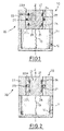
- This loudspeaker 10 essentially comprises a cabinet 11 on top of which is located a voice-coil transducer motor structure 20 comprising a mandrel 21, or moving part, adapted to move along an axis of displacement Z.
- An emissive surface 22 is located at the top of the mandrel 21, at the opposite of a lower side 26 of the mandrel 21, closing in part the top of the cabinet 11. This emissive surface 22 is adapted to transmit the excitation produced by the voice-coil transducer motor structure 20 to the air.
- Upper 22H and lower 22L voice-coils are wound around a lateral face 27 of the mandrel 21 and at least one magnetic element 23 is arranged in use to provide concentration of its resultant magnetic field around the location of an upper 22H and a lower 22L voice-coil. As shown on the figure, the magnetic element 23 surrounds the mandrel 21 at a distance.
- the upper 22H and lower 22L voice-coils are placed in ridges 24 made in the lateral face 27 around the circumference of the mandrel 21.
- the mandrel 21 By driving the current circulating in the upper 22H and the lower 22L voice-coils, the mandrel 21 can be moved along the axis of displacement Z.
- the mandrel 21 is guided along its axis of displacement Z by ferrofluid seals 25 acting as guiding elements.
- ferrofluid seals 25 acting as guiding elements.
- One possible ferrofluid seal is of the type disclosed in the patent document FR2892887 incorporated in its entirety herein by reference.
- a ferrofluid seal 25 is placed in between the moving part 21 and the magnet element 23.
- the ferrofluid seal 25 is placed around the point where the magnetic flux gradient is the largest, here at mid distance from the upper 22H and lower 22L voice-coils.
- ferrofluid seals 25 can help avoid nonlinearities in the movements of the moving part 21 in the coil transducer motor structure 20 compared to known suspension elements that are usually made of elastomer.
- ferrofluid seals 25 act as thermal bridges, allowing the heat generated by the current circulating in the coil to flow through and be dissipated in the magnetic element 23 and in the cabinet 11.
- ferrofluid seals 25 allow the mandrel 21 to be guided along its axis of displacement Z, return stroke means are provided, for the mandrel 21 to be able to reciprocate along its axis Z.
- the volume defined in the cabinet 11 is delimited at the top by the coil transducer motor structure 20, and at least partially by the lower surface 26 of the mandrel 21.
- a hole 12 is made in the cabinet 11, providing a small leakage, the dimensions of the hole being adapted to provide a very long time constant compared to the frequencies at which the coil transducer motor structure 20 operates.
- This hole 12 permits to equalize the pressure in the cabinet 11 for quasi-static or long period movements of the mandrel 21, and to compensate barometric pressure changes.
- the diameter of the hole 12 is comprised between 0.1 and 1 mm for a volume defined in the cabinet 11 of about 10 cubic centiliter.
- Such a return stroke means has the advantage of not introducing non linearities to the voice-coil transducer motor structure 20 unlike elastomer suspension means.
- a suspension wire 13 can be connected towards one end to the lower surface 26 of the mandrel 21 and towards the other end to the cabinet 11 and extends preferably along the displacement axis Z.
- This suspension wire 13 is adapted to prevent the mandrel 21 from being pushed out of the top of the voice-coil transducer motor structure 20 in case of failure of the return stroke means, for example when a strong shock occurs along the displacement axis Z.
- the length of the suspension wire 13 is therefore designed for the suspension wire 13 to enter into action only when the return stroke means are inactive or beyond their working range.
- the mandrel 21 has a monobloc structure, preferably made in the shape of a solid of revolution.
- the monobloc structure is made of one solid piece of material and preferably obtained by casting.
- This monobloc structure is adapted to have its natural mechanical mode of vibration outside of the audible frequency range, that is limited from 20Hz to 20kHz. Therefore, mode coupling is prevented between mechanical modes and acoustical modes.
- the solid monobloc structure of the mandrel 21 allows for the mechanical modes to occur beyond a frequency of 20kHz, or more generally beyond the upper limit of audible sounds.
- the monobloc structure should also prevent the transmission of acoustic waves at least between the lower surface 26 and the emissive surface 22.
- This monobloc structure allows prevention of coupling between mechanical modes and acoustical modes during the excitation of the voice-coil transducer motor structure 20 in the audible frequency range.
- the sound produced by the loudspeaker 10 is made clearer and of higher quality, rising and trailing edges of the acoustic signal being sharper.
- the mandrel is designed to be as light as possible as well as being rigid enough to prevent mode coupling in a bandwidth of audible sounds. For these reasons, the applicant has noticed that a closed pore material is the most suitable material for making the mandrel 21.
- This closed pore material also allows for prevents acoustic waves from being propagated from the bottom face 26 to the emissive surface 22 of the mandrel 21 which would otherwise disturb the acoustical signal generated in the loudspeaker 10.
- This material is an electrical isolator and transparent to the magnetic field generated by the magnet element 23, which allows the coil windings 22H, 22L to be irradiated.
- suitable materials comprise carbon mousse compounds, polystyrene compounds or the like.
- the mandrel's 21 outer surface 27 is covered with a material adapted not to be wetted by ferrofluid seals 25 and for the ferrofluid seals 25 to slide better on the outer surface 27, and for the ferrofluid seals 25 not to disappear by absorption into the mandrel material 21.
- suitable materials for the outer surface 27 comprise metallic materials, preferably aluminum compounds, as coatings. These coatings can be applied on the outer surface 27 by a chemical vapour deposition method for example.
- the mandrel 21 can be obtained by two ways.
- the mandrel 21 can be obtained by providing a chunk of the desired solid material, cutting the chunk of solid material in to the desired shape and preferably coating the outer surface 27 of the mandrel with a material adapted not to be wetted by ferrofluid seals 25, preferably an aluminum compound.
- Ridges 24 are then cut in to the outer surfaces 27 of the mandrel 21, their dimensions and location being adapted to receive coil windings 22H, 22L.
- the mandrel 21 can be obtained by providing a liquid or a powder of the desired material, pouring or injecting the material into a casting die of the desired shape, waiting for solidification of the material, removing the obtained mandrel from the casting die once the material has become solid.
- Ridges 24 can be provided by the same method as in the first variant.
- Coil winding 22H, 22L can also be placed into the casting die prior to the introduction, preferably by injection, of the material and maintained in position until it solidifies. This method allows for the mandrel 21 to be made rapidly and efficiently and the coil windings to be integrated during the moulding process.
- the mandrel 21 has a cylindrical shape.
- the mandrel 21 is able to reciprocate along its displacement axis Z while the ferrofluid seals 25 slide on the outer surface 27.
- the return stroke force is mainly exerted by the interaction between the lower surface 26 and the cabinet 11.
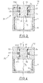
- the mandrel 21 has a monobloc structure in the shape of two circular cone frustum portions, these frustums portions being connected to each other by their smaller surface base side.
- connection of the two frustum portions is designed to fall at mid distance from the upper 22H and lower 22L voice-coils. Therefore, at resting position of the mandrel 21, the ferrofluid seals 25 lie at the location of the connection of the two frustum portions.
- the slopes designed in the outer surface 27 tend to provide an additional return stroke force tending to bring back the mandrel 21 in its resting position when the mandrel 21 moves upwards or downwards.
- the mandrel 21 has a monobloc structure in the shape of two circular cone frustum portions connected to each other by their smaller surface base side to a cylindrical portion.
- the cylindrical portion is located at mid distance from the upper 22H and lower 22L voice-coils. Therefore, at resting position of the mandrel 21, the ferrofluid seals 25 lie against the cylindrical portion.
- the height of this cylindrical portion sets the excursion of the mandrel 21 where the movement sees only the return stroke generated by the cabinet 11.
- the cylindrical portion allows to have a wider ferrofluid seal 25, extending along the cylindrical portion.
- the mandrel 21 has a monobloc structure, in the shape of a paraboloid of revolution.
- This embodiment is advantageous in the ferrofluid seal 25 applying a return stroke force gradually increasing as the mandrel 21 moves away from its resting position and is particularly adapted to positioning of the mandrel 21 along its displacement axis Z.
- the mandrel 21 according to the invention comprises an emissive surface 22 towards the one end of the mandrel 21 adapted to be extending outwards from the loudspeaker 10. This surface replaces the diaphragm that is present in the loudspeakers of the state of the art, in order to prevent the introduction of non linearities.
- the emissive surface 22 can take several shapes. Thus the directivity of the sound produced by the loudspeaker 10 can be tuned.
- Figure 5A illustrates a concave emissive surface 22.
- Figure 5B illustrates a convex emissive surface 22.
Landscapes
- Physics & Mathematics (AREA)
- Engineering & Computer Science (AREA)
- Acoustics & Sound (AREA)
- Signal Processing (AREA)
- Audible-Bandwidth Dynamoelectric Transducers Other Than Pickups (AREA)
Abstract
Description
- This invention relates to a mandrel for a coil transducer motor structure and particularly a mandrel adapted to be placed in a magnetic field in order for the mandrel to reciprocate along an axis of displacement.
- This invention is disclosed in the context of a moving voice-coil transducer motor assembly for a loudspeaker. However, it is believed to be useful in other applications such as microphones, geophones, and shakers.
- Generally, voice-coil transducer motor assemblies, such as those used in traditional electrodynamic loudspeakers, comprise magnetic field generating means adapted to generate a magnetic field in which a coil fixed on a moving part also called mandrel or voice coil support, can be driven by a driving current in order to induce vibrations to a diaphragm connected to the mandrel to produce sound. In order to improve the yield, as well as to reduce the inertia of the loudspeaker, the mandrel that is the moving part and the diaphragm that is attached to it, are designed to be as light as possible.
- To meet these requirements, the mandrel is usually a hollow cylinder and the diaphragm a conical piece of material and both are made of a material such as paper, aluminum, polyimide film such as Kapton®, glass fibre or another light composite material.
- Reducing the weight of these mandrels reduces their rigidity and results in the generation in hitting resonant frequencies. Thus, the frequency response of the voice-coil transducer motor assemblies are affected by nonlinearities.
- These nonlinearities occur because of mode coupling between mechanical modes and acoustical modes, resulting in a transfer of energy between mechanical waves and acoustic waves.
- This problem leads to some harmonics of the sound produced by the loudspeakers integrating such voice-coil transducer motor assemblies, to be hardly audible and almost extinguished, especially at high frequencies. At lower frequencies, some energy is absorbed during the excitation of the assembly and restituted when the excitation is stopped, leading to longer trailing edges, the sound produced in the loudspeaker being somewhat unclear.
- It is an object of the invention to provide an improved mandrel component for a coil transducer motor assembly and in particular such an assembly that reduces or extinguishes mode coupling and its resulting drawbacks.
- Thereto, the present invention provides a mandrel for a coil transducer motor assembly according to claim 1.
- By providing a monobloc mandrel with a natural mechanical mode of vibration outside of the audible frequency range, mode coupling between mechanical modes and acoustic modes whereby mechanical energy is exchanged between mechanical modes and acoustic modes occurs only beyond an upper audible limit frequency, usually around 20kHz.
- Further advantageous features of the invention form the subject matter of the dependant claims:
- said monobloc structure of the mandrel may comprise a closed pore material, that results in having a rigid as well as a light moving part;
- the monobloc structure of the mandrel may comprise a material that is an electrical isolator and transparent to the magnetic field generated by the magnet element;
- the monobloc structure of the mandrel may comprise a carbon mousse compound;
- the monobloc structure of the mandrel may comprise a polystyrene compound;
- the outer surface of the mandrel may be coated with a material that is resistant to being wetted through contact with a ferrofluid seal;
- the outer surface of the mandrel may be coated with a metallic material, preferably comprising an aluminium compound;
- ridges adapted to receive coil windings may be defined in the outer surface around the circumference of the mandrel;
- the monobloc structure may be obtained by a moulding process, preferably injection casting;
- the monobloc structure comprises coil windings may be integrated therein during the moulding process;
- an emissive surface may be provided towards one end of the mandrel;
- the emissive surface may be concave;
- the emissive surface may be convex;
- the mandrel may be made in the shape of a solid of revolution;
- the mandrel may be made in a cylindrical shape
- the mandrel may be made in a two circular cone frustum portion shape, the frustums portions being connected to each other by their smaller surface base side
- the mandrel may be made in a two circular cone frustum portion shape connected to each other by their smaller surface base side to a cylindrical portion
- the mandrel may be made in a paraboloid of revolution shape.
- The invention also relates to a method of manufacturing a mandrel according to the invention, the method including the steps of:
- providing a liquid or a powder of the desired material into a casting die of the desired shape,
- setting the material to form said mandrel,
- removing the obtained mandrel from the casting die.
- Further advantageous features of the method of manufacturing a mandrel according to the invention form the subject matter of the dependant claims:
- the method may include the step of cutting ridges in the outer surface of the mandrel;
- the method may include the step of providing coil winding into the casting die before providing the material into the casting die and maintaining the coil winding in position until the material sets.
- The invention also relates to a coil transducer motor structure incorporating at least one magnetic element arranged in use to provide a path for magnetic flux between the ends of at least one coil the coil being wound around a reciprocating mandrel according to the invention.
- The invention also relates to a loudspeaker incorporating a coil transducer motor structure according to the invention fixed on to a cabinet providing return stroke means.
- The loudspeaker may incorporate a suspension wire in the cabinet that may be connected towards one end to a lower surface of the mandrel and towards the other end to the cabinet and may extend preferably along the displacement axis Z.
- The present invention will now be described by way of example only and with reference to the accompanying drawings, in which:
-
figure 1 is a schematic representation of a cross-section of a voice-coil transducer motor assembly comprising a monobloc mandrel according to a first embodiment; -
figure 2 is a schematic representation of a cross-section of a voice-coil transducer motor assembly comprising a monobloc mandrel according to a second embodiment; -
figure 3 is a schematic representation of a cross-section of a voice-coil transducer motor assembly comprising a monobloc mandrel according to a third embodiment; -
figure 4 is a schematic representation of a cross-section of a voice-coil transducer motor assembly comprising a monobloc mandrel according to a fourth embodiment; and -
figure 5A and figure 5B represent respectively views in perspective of mandrels having concave and convex emissive surfaces. - Referring to the figures and for the moment in particular to
Figure 1 , a cross-section through aloudspeaker 10 is illustrated. - This
loudspeaker 10 essentially comprises acabinet 11 on top of which is located a voice-coiltransducer motor structure 20 comprising amandrel 21, or moving part, adapted to move along an axis of displacement Z. Anemissive surface 22 is located at the top of themandrel 21, at the opposite of alower side 26 of themandrel 21, closing in part the top of thecabinet 11. Thisemissive surface 22 is adapted to transmit the excitation produced by the voice-coiltransducer motor structure 20 to the air. - Upper 22H and lower 22L voice-coils are wound around a
lateral face 27 of themandrel 21 and at least onemagnetic element 23 is arranged in use to provide concentration of its resultant magnetic field around the location of an upper 22H and a lower 22L voice-coil. As shown on the figure, themagnetic element 23 surrounds themandrel 21 at a distance. - On
figure 1 , the upper 22H and lower 22L voice-coils are placed inridges 24 made in thelateral face 27 around the circumference of themandrel 21. - By driving the current circulating in the upper 22H and the lower 22L voice-coils, the
mandrel 21 can be moved along the axis of displacement Z. - The
mandrel 21 is guided along its axis of displacement Z byferrofluid seals 25 acting as guiding elements. One possible ferrofluid seal is of the type disclosed in the patent documentFR2892887 - As shown on
figure 1 , aferrofluid seal 25 is placed in between the movingpart 21 and themagnet element 23. Theferrofluid seal 25 is placed around the point where the magnetic flux gradient is the largest, here at mid distance from the upper 22H and lower 22L voice-coils. - Use of
ferrofluid seals 25 can help avoid nonlinearities in the movements of the movingpart 21 in the coiltransducer motor structure 20 compared to known suspension elements that are usually made of elastomer. - Moreover,
ferrofluid seals 25 act as thermal bridges, allowing the heat generated by the current circulating in the coil to flow through and be dissipated in themagnetic element 23 and in thecabinet 11. - If the
ferrofluid seals 25 allow themandrel 21 to be guided along its axis of displacement Z, return stroke means are provided, for themandrel 21 to be able to reciprocate along its axis Z. - These means take advantage of the volume change in the
cabinet 11 when themandrel 21 moves along the axis of displacement Z. The volume defined in thecabinet 11 is delimited at the top by the coiltransducer motor structure 20, and at least partially by thelower surface 26 of themandrel 21. - A
hole 12 is made in thecabinet 11, providing a small leakage, the dimensions of the hole being adapted to provide a very long time constant compared to the frequencies at which the coiltransducer motor structure 20 operates. Thishole 12 permits to equalize the pressure in thecabinet 11 for quasi-static or long period movements of themandrel 21, and to compensate barometric pressure changes. - For example, the diameter of the
hole 12 is comprised between 0.1 and 1 mm for a volume defined in thecabinet 11 of about 10 cubic centiliter. - When the
mandrel 21 moves upwards, the pressure in thecabinet 11 decreases, a depression is created and a return stroke force is generated retaining themandrel 21 by itslower surface 26. A small quantity of air is sucked into thecabinet 11 through thehole 12, to slowly increase the pressure in thecabinet 11. - When the
mandrel 21 moves downwards, the pressure in thecabinet 11 increases, some air is slowly expelled out of thecabinet 11 through thehole 12. - At usual operating frequency range, the amount of air exchange is negligible.
- Thus, the
mandrel 21 is retained by itslower surface 26 by an effect of suction. Such a return stroke means has the advantage of not introducing non linearities to the voice-coiltransducer motor structure 20 unlike elastomer suspension means. - A
suspension wire 13 can be connected towards one end to thelower surface 26 of themandrel 21 and towards the other end to thecabinet 11 and extends preferably along the displacement axis Z. - This
suspension wire 13 is adapted to prevent themandrel 21 from being pushed out of the top of the voice-coiltransducer motor structure 20 in case of failure of the return stroke means, for example when a strong shock occurs along the displacement axis Z. - The length of the
suspension wire 13 is therefore designed for thesuspension wire 13 to enter into action only when the return stroke means are inactive or beyond their working range. - According to the invention, the
mandrel 21 has a monobloc structure, preferably made in the shape of a solid of revolution. The monobloc structure is made of one solid piece of material and preferably obtained by casting. This monobloc structure is adapted to have its natural mechanical mode of vibration outside of the audible frequency range, that is limited from 20Hz to 20kHz. Therefore, mode coupling is prevented between mechanical modes and acoustical modes. The solid monobloc structure of themandrel 21 allows for the mechanical modes to occur beyond a frequency of 20kHz, or more generally beyond the upper limit of audible sounds. The monobloc structure should also prevent the transmission of acoustic waves at least between thelower surface 26 and theemissive surface 22. - This monobloc structure allows prevention of coupling between mechanical modes and acoustical modes during the excitation of the voice-coil
transducer motor structure 20 in the audible frequency range. Thus the sound produced by theloudspeaker 10 is made clearer and of higher quality, rising and trailing edges of the acoustic signal being sharper. - To improve yield and efficiency of the voice-coil
transducer motor structure 20, the mandrel is designed to be as light as possible as well as being rigid enough to prevent mode coupling in a bandwidth of audible sounds. For these reasons, the applicant has noticed that a closed pore material is the most suitable material for making themandrel 21. - This closed pore material also allows for prevents acoustic waves from being propagated from the
bottom face 26 to theemissive surface 22 of themandrel 21 which would otherwise disturb the acoustical signal generated in theloudspeaker 10. - This material is an electrical isolator and transparent to the magnetic field generated by the
magnet element 23, which allows thecoil windings - By way of example, suitable materials comprise carbon mousse compounds, polystyrene compounds or the like.
- The mandrel's 21
outer surface 27 is covered with a material adapted not to be wetted byferrofluid seals 25 and for the ferrofluid seals 25 to slide better on theouter surface 27, and for the ferrofluid seals 25 not to disappear by absorption into themandrel material 21. - By way of example, suitable materials for the
outer surface 27 comprise metallic materials, preferably aluminum compounds, as coatings. These coatings can be applied on theouter surface 27 by a chemical vapour deposition method for example. - According to the invention, the
mandrel 21 can be obtained by two ways. - In a first variant, the
mandrel 21 can be obtained by providing a chunk of the desired solid material, cutting the chunk of solid material in to the desired shape and preferably coating theouter surface 27 of the mandrel with a material adapted not to be wetted byferrofluid seals 25, preferably an aluminum compound. -
Ridges 24 are then cut in to theouter surfaces 27 of themandrel 21, their dimensions and location being adapted to receivecoil windings - In a second variant, the
mandrel 21 can be obtained by providing a liquid or a powder of the desired material, pouring or injecting the material into a casting die of the desired shape, waiting for solidification of the material, removing the obtained mandrel from the casting die once the material has become solid. -
Ridges 24 can be provided by the same method as in the first variant. - Coil winding 22H, 22L can also be placed into the casting die prior to the introduction, preferably by injection, of the material and maintained in position until it solidifies. This method allows for the
mandrel 21 to be made rapidly and efficiently and the coil windings to be integrated during the moulding process. - According to the first embodiment of the invention as disclosed in combination with
figure 1 , themandrel 21 has a cylindrical shape. Themandrel 21 is able to reciprocate along its displacement axis Z while the ferrofluid seals 25 slide on theouter surface 27. The return stroke force is mainly exerted by the interaction between thelower surface 26 and thecabinet 11. - According to a second embodiment of the invention shown on
figure 2 , themandrel 21 has a monobloc structure in the shape of two circular cone frustum portions, these frustums portions being connected to each other by their smaller surface base side. - The location of the connection of the two frustum portions is designed to fall at mid distance from the upper 22H and lower 22L voice-coils. Therefore, at resting position of the
mandrel 21, the ferrofluid seals 25 lie at the location of the connection of the two frustum portions. The slopes designed in theouter surface 27 tend to provide an additional return stroke force tending to bring back themandrel 21 in its resting position when themandrel 21 moves upwards or downwards. - According to a third embodiment of the invention shown on
figure 3 , themandrel 21 has a monobloc structure in the shape of two circular cone frustum portions connected to each other by their smaller surface base side to a cylindrical portion. The cylindrical portion is located at mid distance from the upper 22H and lower 22L voice-coils. Therefore, at resting position of themandrel 21, the ferrofluid seals 25 lie against the cylindrical portion. The height of this cylindrical portion sets the excursion of themandrel 21 where the movement sees only the return stroke generated by thecabinet 11. The cylindrical portion allows to have awider ferrofluid seal 25, extending along the cylindrical portion. - According to a fourth embodiment of the invention shown on
figure 4 , themandrel 21 has a monobloc structure, in the shape of a paraboloid of revolution. This embodiment is advantageous in theferrofluid seal 25 applying a return stroke force gradually increasing as themandrel 21 moves away from its resting position and is particularly adapted to positioning of themandrel 21 along its displacement axis Z. - The
mandrel 21 according to the invention comprises anemissive surface 22 towards the one end of themandrel 21 adapted to be extending outwards from theloudspeaker 10. This surface replaces the diaphragm that is present in the loudspeakers of the state of the art, in order to prevent the introduction of non linearities. - Depending on the characteristic of the field of emission the
loudspeaker 10 is intended for, theemissive surface 22 can take several shapes. Thus the directivity of the sound produced by theloudspeaker 10 can be tuned. -
Figure 5A illustrates a concaveemissive surface 22. -
Figure 5B illustrates a convexemissive surface 22.
Claims (14)
- A mandrel (21) for a coil transducer motor structure (10) adapted to receive at least one coil (22H, 22L) wound therearound arranged in use for displacing the mandrel (21) along an axis of displacement Z, as a current is driven through the coils (22H, 22L) when the mandrel (21) is placed in a magnetic field, characterized in that the mandrel (21) has a monobloc structure with a natural mechanical mode of vibration outside of the audible frequency range.
- A mandrel (21) according to the preceding claim characterized in that the monobloc structure of the mandrel (21) comprises a closed pore material such as a carbon mousse compound, or a polystyrene compound.
- A mandrel (21) according to claim 1 or claim 2 characterized in that the monobloc structure of the mandrel (21) comprises a material that is an electrical isolator and transparent to the magnetic field.
- A mandrel (21) according to any one of the preceding claims characterized in that the outer surface (27) is coated with a material that is resistant to being wetted through contact with a ferrofluid seal (25), such as a metallic material, which preferably comprises an aluminium compound.
- A mandrel (21) according to any one of the preceding claims characterized in that ridges (24) adapted to receive coil windings (22H, 22L) are defined in the outer surface (27) around the circumference of the mandrel (21).
- A mandrel (21) according to any one of the preceding claims characterized in that there is provided an emissive surface (22) towards one end of the mandrel (21), preferably concave, or convex.
- A mandrel (21) according to any one of the preceding claims characterized in that it is made in the shape of a solid of revolution.
- A mandrel (21) according to the preceding claim characterized in that the shape of the mandrel (21) is chosen amongst:- a cylindrical shape,- a two circular cone frustum portion shape, the frustum portions being connected to each other by their smaller surface base side, or- a two circular cone frustum portion shape connected to each other by their smaller surface base side to a cylindrical portion, or- a paraboloid of revolution shape.
- Method of manufacturing a mandrel according to any preceding claim, the method including the steps of:- providing a liquid or a powder of the desired material into a casting die of the desired shape,- setting the material to form said mandrel,- removing the obtained mandrel from the casting die.
- Method of manufacturing a mandrel according to the preceding claim, the method including the step of cutting ridges (24) the outer surfaces (27) of the mandrel (21).
- Method of manufacturing a mandrel according to claim 9, the method including the step of providing coil winding (22H,22L) into the casting die before providing the material into the casting die and maintaining the coil winding in position until the material sets.
- Coil transducer motor structure (20), comprising at least one magnetic element (23) arranged in use to provide a path for magnetic flux between the ends of at least one coil (22H, 22L) characterized in that the coil (22H, 22L) is wound around a reciprocating mandrel (21) according to any preceding claim.
- Loudspeaker (10) incorporating a coil transducer motor structure (20) according to the preceding claim fixed on to of a cabinet (11) providing return stroke means.
- Loudspeaker (10) according to the preceding claim characterized in that a suspension wire (13) is incorporated in the cabinet (11) and connected towards one end to the lower surface (26) of the mandrel (21) and towards the other end to the cabinet (11) and extends preferably along the displacement axis Z.
Priority Applications (11)
| Application Number | Priority Date | Filing Date | Title |
|---|---|---|---|
| EP08290652.0A EP2141939B1 (en) | 2008-07-02 | 2008-07-02 | Mandrel for a coil transducer motor structure |
| KR1020107029854A KR101535698B1 (en) | 2008-07-02 | 2009-07-02 | Voice coil support for a coil transducer motor structure |
| PCT/EP2009/004804 WO2010000481A1 (en) | 2008-07-02 | 2009-07-02 | Voice coil support for a coil transducer motor structure |
| JP2011515243A JP5442728B2 (en) | 2008-07-02 | 2009-07-02 | Voice coil support device with coil type converter motor structure |
| CN200980125439.4A CN102077610B (en) | 2008-07-02 | 2009-07-02 | Voice coil support for coil transducer motor construction |
| CA2729066A CA2729066C (en) | 2008-07-02 | 2009-07-02 | Voice coil support for a coil transducer motor structure |
| MX2010014397A MX2010014397A (en) | 2008-07-02 | 2009-07-02 | Voice coil support for a coil transducer motor structure. |
| US13/000,452 US8971564B2 (en) | 2008-07-02 | 2009-07-02 | Voice coil support for a coil transducer motor structure |
| AU2009266026A AU2009266026B2 (en) | 2008-07-02 | 2009-07-02 | Voice coil support for a coil transducer motor structure |
| RU2010154387/28A RU2525571C2 (en) | 2008-07-02 | 2009-07-02 | Voice coil support for motor unit of coil converter |
| BRPI0914701-2A BRPI0914701B1 (en) | 2008-07-02 | 2009-07-02 | voice coil holder for a coil transducer motor frame, method for manufacturing the same, coil transducer motor frame, and, speaker |
Applications Claiming Priority (1)
| Application Number | Priority Date | Filing Date | Title |
|---|---|---|---|
| EP08290652.0A EP2141939B1 (en) | 2008-07-02 | 2008-07-02 | Mandrel for a coil transducer motor structure |
Publications (2)
| Publication Number | Publication Date |
|---|---|
| EP2141939A1 true EP2141939A1 (en) | 2010-01-06 |
| EP2141939B1 EP2141939B1 (en) | 2016-11-09 |
Family
ID=40010785
Family Applications (1)
| Application Number | Title | Priority Date | Filing Date |
|---|---|---|---|
| EP08290652.0A Not-in-force EP2141939B1 (en) | 2008-07-02 | 2008-07-02 | Mandrel for a coil transducer motor structure |
Country Status (11)
| Country | Link |
|---|---|
| US (1) | US8971564B2 (en) |
| EP (1) | EP2141939B1 (en) |
| JP (1) | JP5442728B2 (en) |
| KR (1) | KR101535698B1 (en) |
| CN (1) | CN102077610B (en) |
| AU (1) | AU2009266026B2 (en) |
| BR (1) | BRPI0914701B1 (en) |
| CA (1) | CA2729066C (en) |
| MX (1) | MX2010014397A (en) |
| RU (1) | RU2525571C2 (en) |
| WO (1) | WO2010000481A1 (en) |
Families Citing this family (5)
| Publication number | Priority date | Publication date | Assignee | Title |
|---|---|---|---|---|
| JP2685528B2 (en) | 1988-09-07 | 1997-12-03 | 株式会社日立製作所 | Noise control device for straddle type monorail vehicle |
| JP5374286B2 (en) | 2009-09-14 | 2013-12-25 | 富士フイルム株式会社 | Protective film and solar cell front sheet |
| US9942662B2 (en) | 2016-06-14 | 2018-04-10 | Bose Corporation | Electro-acoustic driver having compliant diaphragm with stiffening element |
| CN106255013B (en) * | 2016-08-18 | 2022-04-05 | 歌尔股份有限公司 | Voice coil structure |
| JP6265518B1 (en) * | 2017-09-28 | 2018-01-24 | 準 植木 | Speaker device |
Citations (6)
| Publication number | Priority date | Publication date | Assignee | Title |
|---|---|---|---|---|
| GB707730A (en) * | 1951-05-22 | 1954-04-21 | Baxter Brothers And Company Lt | Improvements in bobbins for use in yarn spinning, twisting and similar machines |
| JPS54134618A (en) * | 1978-04-12 | 1979-10-19 | Hitachi Ltd | Voice coil bobbin |
| GB2281171A (en) * | 1993-08-16 | 1995-02-22 | Sony Corp | Coil arrangement for a motional feedback loudspeaker |
| US20020057818A1 (en) * | 2000-10-31 | 2002-05-16 | Yasuhisa Abe | Speaker apparatus |
| CN1463898A (en) * | 2002-06-18 | 2003-12-31 | 顾文波 | Cork plug for bottle with protecting film |
| FR2892887A1 (en) | 2005-11-03 | 2007-05-04 | Bernard Richoux | Electrodynamic transducer e.g. loudspeaker, for generating sound waves, has confinement units to confine magnetic field in gap to form bilateral seals in gap for guiding coil and forming pneumatic seal between front and rear faces of dome |
Family Cites Families (21)
| Publication number | Priority date | Publication date | Assignee | Title |
|---|---|---|---|---|
| US3073916A (en) * | 1958-11-24 | 1963-01-15 | Muter Company | Blast-proof water-proof loudspeaker |
| DE2607390C2 (en) * | 1976-02-24 | 1982-09-23 | Braun Ag, 6000 Frankfurt | Dynamic loudspeaker with a high load capacity |
| SU888337A1 (en) * | 1979-09-21 | 1981-12-07 | Институт Тепломассообмена Им.А.В.Лыкова Ан Бсср | Composition for filling magnetic circuit gap of dynamic loudspeaker |
| US4410768A (en) * | 1980-07-23 | 1983-10-18 | Nippon Gakki Seizo Kabushiki Kaisha | Electro-acoustic transducer |
| US4443667A (en) * | 1982-01-11 | 1984-04-17 | Bell Telephone Laboratories, Incorporated | Electromagnetic transducer |
| US5734734A (en) * | 1995-12-29 | 1998-03-31 | Proni; Lucio | Audio voice coil adaptor ring |
| JPH1188986A (en) * | 1997-09-02 | 1999-03-30 | Sony Corp | Speaker device |
| GB0029098D0 (en) * | 2000-11-30 | 2001-01-10 | New Transducers Ltd | Vibration transducer |
| US7035424B1 (en) * | 2001-05-18 | 2006-04-25 | Brandt Eugene P | Loudspeaker having an inner lead wire system and related method of protecting the lead wires |
| EP1420610A4 (en) * | 2001-07-23 | 2006-06-28 | Toshio Chikama | Magnetic shielding of loud speaker sensing coil |
| JP2003199194A (en) * | 2001-12-25 | 2003-07-11 | Pioneer Electronic Corp | Speaker device |
| US20030133581A1 (en) * | 2002-01-07 | 2003-07-17 | Klayman Arnold I. | User configurable multi-component speaker panel |
| JP3797561B2 (en) * | 2003-11-18 | 2006-07-19 | ソニー株式会社 | Speaker device |
| JP2006005852A (en) * | 2004-06-21 | 2006-01-05 | Pioneer Electronic Corp | Speaker system |
| JP4137869B2 (en) * | 2004-10-25 | 2008-08-20 | パイオニア株式会社 | Speaker device and manufacturing method thereof |
| JP2006303982A (en) * | 2005-04-21 | 2006-11-02 | Pioneer Electronic Corp | Voice coil body and speaker |
| JP2007020024A (en) * | 2005-07-11 | 2007-01-25 | Yamaha Corp | Linear motor type loudspeaker |
| US7729504B2 (en) * | 2006-02-14 | 2010-06-01 | Ferrotec Corporation | Ferrofluid centered voice coil speaker |
| JP2008141663A (en) * | 2006-12-05 | 2008-06-19 | Onkyo Corp | speaker |
| US20080137902A1 (en) * | 2006-12-07 | 2008-06-12 | Bohlender Jack T | Highly elongated loudspeaker and motor |
| FR2919978B1 (en) * | 2007-08-09 | 2011-04-29 | Gilles Milot | ELECTRODYNAMIC TRANSDUCER, IN PARTICULAR OF THE SPEAKER TYPE, WITH FERROFLUID SUSPENSION AND ASSOCIATED DEVICES |
-
2008
- 2008-07-02 EP EP08290652.0A patent/EP2141939B1/en not_active Not-in-force
-
2009
- 2009-07-02 KR KR1020107029854A patent/KR101535698B1/en not_active Expired - Fee Related
- 2009-07-02 US US13/000,452 patent/US8971564B2/en not_active Expired - Fee Related
- 2009-07-02 CA CA2729066A patent/CA2729066C/en not_active Expired - Fee Related
- 2009-07-02 AU AU2009266026A patent/AU2009266026B2/en not_active Ceased
- 2009-07-02 RU RU2010154387/28A patent/RU2525571C2/en not_active IP Right Cessation
- 2009-07-02 WO PCT/EP2009/004804 patent/WO2010000481A1/en not_active Ceased
- 2009-07-02 BR BRPI0914701-2A patent/BRPI0914701B1/en not_active IP Right Cessation
- 2009-07-02 MX MX2010014397A patent/MX2010014397A/en active IP Right Grant
- 2009-07-02 CN CN200980125439.4A patent/CN102077610B/en not_active Expired - Fee Related
- 2009-07-02 JP JP2011515243A patent/JP5442728B2/en not_active Expired - Fee Related
Patent Citations (6)
| Publication number | Priority date | Publication date | Assignee | Title |
|---|---|---|---|---|
| GB707730A (en) * | 1951-05-22 | 1954-04-21 | Baxter Brothers And Company Lt | Improvements in bobbins for use in yarn spinning, twisting and similar machines |
| JPS54134618A (en) * | 1978-04-12 | 1979-10-19 | Hitachi Ltd | Voice coil bobbin |
| GB2281171A (en) * | 1993-08-16 | 1995-02-22 | Sony Corp | Coil arrangement for a motional feedback loudspeaker |
| US20020057818A1 (en) * | 2000-10-31 | 2002-05-16 | Yasuhisa Abe | Speaker apparatus |
| CN1463898A (en) * | 2002-06-18 | 2003-12-31 | 顾文波 | Cork plug for bottle with protecting film |
| FR2892887A1 (en) | 2005-11-03 | 2007-05-04 | Bernard Richoux | Electrodynamic transducer e.g. loudspeaker, for generating sound waves, has confinement units to confine magnetic field in gap to form bilateral seals in gap for guiding coil and forming pneumatic seal between front and rear faces of dome |
Also Published As
| Publication number | Publication date |
|---|---|
| BRPI0914701A2 (en) | 2015-10-20 |
| MX2010014397A (en) | 2011-05-02 |
| JP5442728B2 (en) | 2014-03-12 |
| KR20110025675A (en) | 2011-03-10 |
| CN102077610A (en) | 2011-05-25 |
| JP2011526452A (en) | 2011-10-06 |
| AU2009266026B2 (en) | 2014-05-29 |
| CA2729066C (en) | 2017-05-23 |
| AU2009266026A1 (en) | 2010-01-07 |
| BRPI0914701B1 (en) | 2019-11-05 |
| KR101535698B1 (en) | 2015-07-09 |
| CA2729066A1 (en) | 2010-01-07 |
| WO2010000481A1 (en) | 2010-01-07 |
| CN102077610B (en) | 2015-08-19 |
| US8971564B2 (en) | 2015-03-03 |
| EP2141939B1 (en) | 2016-11-09 |
| RU2010154387A (en) | 2012-08-10 |
| RU2525571C2 (en) | 2014-08-20 |
| US20110103638A1 (en) | 2011-05-05 |
Similar Documents
| Publication | Publication Date | Title |
|---|---|---|
| KR101377381B1 (en) | Ferrofluid Centered Voice Coil Speaker | |
| EP1962551B1 (en) | A moving armature receiver | |
| EP2141939B1 (en) | Mandrel for a coil transducer motor structure | |
| US7921540B2 (en) | System of component s usable in the manufacture of an acoustic transducer | |
| EP2448290A1 (en) | Multifunctional micro speaker | |
| CN113993049B (en) | MEMS digital loudspeaker design method | |
| CN103597852A (en) | Electromechanical-electroacoustic transducer with low thickness and high stroke and method of manufacturing the same | |
| CN101489169A (en) | Speaker unit | |
| CN107105371A (en) | A kind of vibrating diaphragm mechanism and its preparation technology applied to receiver | |
| KR101755329B1 (en) | Hybrid speaker and vibration module used therein | |
| JP4790452B2 (en) | Voice coil bobbin and speaker device | |
| CN108449694B (en) | Vibrating diaphragm and telephone receiver | |
| US20240214739A1 (en) | High excursion, low distortion and low depth speaker | |
| JP2008288635A (en) | Electroacoustic transducer | |
| KR101268499B1 (en) | A speaker | |
| JP5586629B2 (en) | Movable part device and electromechanical transducer equipped with such a movable part device | |
| KR101802841B1 (en) | Moving coil type underwater sound projector having contact surface bobbin structure | |
| EP1096830A2 (en) | High frequency transducer | |
| JP2012257003A (en) | Acoustic device and vibration transmission method of the same | |
| JP2008256110A (en) | Damping device and offset correcting method for damping device | |
| KR101068783B1 (en) | Acoustic transducer and manufacturing method thereof | |
| JP4757746B2 (en) | Diaphragm for speaker, speaker and manufacturing method thereof | |
| EP3289780A1 (en) | Deep-drawn foil-based miniature diaphragm assembly | |
| WO2011013462A1 (en) | Electroacoustic transducer having vibration function | |
| JP2010103894A (en) | Electro-acoustic transducer |
Legal Events
| Date | Code | Title | Description |
|---|---|---|---|
| PUAI | Public reference made under article 153(3) epc to a published international application that has entered the european phase |
Free format text: ORIGINAL CODE: 0009012 |
|
| AK | Designated contracting states |
Kind code of ref document: A1 Designated state(s): AT BE BG CH CY CZ DE DK EE ES FI FR GB GR HR HU IE IS IT LI LT LU LV MC MT NL NO PL PT RO SE SI SK TR |
|
| AX | Request for extension of the european patent |
Extension state: AL BA MK RS |
|
| RIN1 | Information on inventor provided before grant (corrected) |
Inventor name: REMY, MATHIAS Inventor name: GUYADER, GAEL Inventor name: LEMARQUAND, GUY |
|
| 17P | Request for examination filed |
Effective date: 20100330 |
|
| 17Q | First examination report despatched |
Effective date: 20100429 |
|
| AKX | Designation fees paid |
Designated state(s): AT BE BG CH CY CZ DE DK EE ES FI FR GB GR HR HU IE IS IT LI LT LU LV MC MT NL NO PL PT RO SE SI SK TR |
|
| GRAP | Despatch of communication of intention to grant a patent |
Free format text: ORIGINAL CODE: EPIDOSNIGR1 |
|
| INTG | Intention to grant announced |
Effective date: 20160629 |
|
| GRAS | Grant fee paid |
Free format text: ORIGINAL CODE: EPIDOSNIGR3 |
|
| GRAA | (expected) grant |
Free format text: ORIGINAL CODE: 0009210 |
|
| AK | Designated contracting states |
Kind code of ref document: B1 Designated state(s): AT BE BG CH CY CZ DE DK EE ES FI FR GB GR HR HU IE IS IT LI LT LU LV MC MT NL NO PL PT RO SE SI SK TR |
|
| REG | Reference to a national code |
Ref country code: GB Ref legal event code: FG4D |
|
| REG | Reference to a national code |
Ref country code: AT Ref legal event code: REF Ref document number: 844867 Country of ref document: AT Kind code of ref document: T Effective date: 20161115 Ref country code: CH Ref legal event code: EP |
|
| REG | Reference to a national code |
Ref country code: IE Ref legal event code: FG4D |
|
| REG | Reference to a national code |
Ref country code: DE Ref legal event code: R096 Ref document number: 602008047260 Country of ref document: DE |
|
| PG25 | Lapsed in a contracting state [announced via postgrant information from national office to epo] |
Ref country code: LV Free format text: LAPSE BECAUSE OF FAILURE TO SUBMIT A TRANSLATION OF THE DESCRIPTION OR TO PAY THE FEE WITHIN THE PRESCRIBED TIME-LIMIT Effective date: 20161109 |
|
| REG | Reference to a national code |
Ref country code: LT Ref legal event code: MG4D |
|
| REG | Reference to a national code |
Ref country code: NL Ref legal event code: MP Effective date: 20161109 |
|
| REG | Reference to a national code |
Ref country code: AT Ref legal event code: MK05 Ref document number: 844867 Country of ref document: AT Kind code of ref document: T Effective date: 20161109 |
|
| PG25 | Lapsed in a contracting state [announced via postgrant information from national office to epo] |
Ref country code: SE Free format text: LAPSE BECAUSE OF FAILURE TO SUBMIT A TRANSLATION OF THE DESCRIPTION OR TO PAY THE FEE WITHIN THE PRESCRIBED TIME-LIMIT Effective date: 20161109 Ref country code: GR Free format text: LAPSE BECAUSE OF FAILURE TO SUBMIT A TRANSLATION OF THE DESCRIPTION OR TO PAY THE FEE WITHIN THE PRESCRIBED TIME-LIMIT Effective date: 20170210 Ref country code: NO Free format text: LAPSE BECAUSE OF FAILURE TO SUBMIT A TRANSLATION OF THE DESCRIPTION OR TO PAY THE FEE WITHIN THE PRESCRIBED TIME-LIMIT Effective date: 20170209 Ref country code: LT Free format text: LAPSE BECAUSE OF FAILURE TO SUBMIT A TRANSLATION OF THE DESCRIPTION OR TO PAY THE FEE WITHIN THE PRESCRIBED TIME-LIMIT Effective date: 20161109 Ref country code: NL Free format text: LAPSE BECAUSE OF FAILURE TO SUBMIT A TRANSLATION OF THE DESCRIPTION OR TO PAY THE FEE WITHIN THE PRESCRIBED TIME-LIMIT Effective date: 20161109 |
|
| PG25 | Lapsed in a contracting state [announced via postgrant information from national office to epo] |
Ref country code: PT Free format text: LAPSE BECAUSE OF FAILURE TO SUBMIT A TRANSLATION OF THE DESCRIPTION OR TO PAY THE FEE WITHIN THE PRESCRIBED TIME-LIMIT Effective date: 20170309 Ref country code: FI Free format text: LAPSE BECAUSE OF FAILURE TO SUBMIT A TRANSLATION OF THE DESCRIPTION OR TO PAY THE FEE WITHIN THE PRESCRIBED TIME-LIMIT Effective date: 20161109 Ref country code: HR Free format text: LAPSE BECAUSE OF FAILURE TO SUBMIT A TRANSLATION OF THE DESCRIPTION OR TO PAY THE FEE WITHIN THE PRESCRIBED TIME-LIMIT Effective date: 20161109 Ref country code: IS Free format text: LAPSE BECAUSE OF FAILURE TO SUBMIT A TRANSLATION OF THE DESCRIPTION OR TO PAY THE FEE WITHIN THE PRESCRIBED TIME-LIMIT Effective date: 20170309 Ref country code: ES Free format text: LAPSE BECAUSE OF FAILURE TO SUBMIT A TRANSLATION OF THE DESCRIPTION OR TO PAY THE FEE WITHIN THE PRESCRIBED TIME-LIMIT Effective date: 20161109 Ref country code: AT Free format text: LAPSE BECAUSE OF FAILURE TO SUBMIT A TRANSLATION OF THE DESCRIPTION OR TO PAY THE FEE WITHIN THE PRESCRIBED TIME-LIMIT Effective date: 20161109 Ref country code: PL Free format text: LAPSE BECAUSE OF FAILURE TO SUBMIT A TRANSLATION OF THE DESCRIPTION OR TO PAY THE FEE WITHIN THE PRESCRIBED TIME-LIMIT Effective date: 20161109 |
|
| REG | Reference to a national code |
Ref country code: FR Ref legal event code: PLFP Year of fee payment: 10 |
|
| PG25 | Lapsed in a contracting state [announced via postgrant information from national office to epo] |
Ref country code: EE Free format text: LAPSE BECAUSE OF FAILURE TO SUBMIT A TRANSLATION OF THE DESCRIPTION OR TO PAY THE FEE WITHIN THE PRESCRIBED TIME-LIMIT Effective date: 20161109 Ref country code: SK Free format text: LAPSE BECAUSE OF FAILURE TO SUBMIT A TRANSLATION OF THE DESCRIPTION OR TO PAY THE FEE WITHIN THE PRESCRIBED TIME-LIMIT Effective date: 20161109 Ref country code: DK Free format text: LAPSE BECAUSE OF FAILURE TO SUBMIT A TRANSLATION OF THE DESCRIPTION OR TO PAY THE FEE WITHIN THE PRESCRIBED TIME-LIMIT Effective date: 20161109 Ref country code: CZ Free format text: LAPSE BECAUSE OF FAILURE TO SUBMIT A TRANSLATION OF THE DESCRIPTION OR TO PAY THE FEE WITHIN THE PRESCRIBED TIME-LIMIT Effective date: 20161109 Ref country code: RO Free format text: LAPSE BECAUSE OF FAILURE TO SUBMIT A TRANSLATION OF THE DESCRIPTION OR TO PAY THE FEE WITHIN THE PRESCRIBED TIME-LIMIT Effective date: 20161109 |
|
| REG | Reference to a national code |
Ref country code: DE Ref legal event code: R097 Ref document number: 602008047260 Country of ref document: DE |
|
| PG25 | Lapsed in a contracting state [announced via postgrant information from national office to epo] |
Ref country code: BG Free format text: LAPSE BECAUSE OF FAILURE TO SUBMIT A TRANSLATION OF THE DESCRIPTION OR TO PAY THE FEE WITHIN THE PRESCRIBED TIME-LIMIT Effective date: 20170209 Ref country code: BE Free format text: LAPSE BECAUSE OF FAILURE TO SUBMIT A TRANSLATION OF THE DESCRIPTION OR TO PAY THE FEE WITHIN THE PRESCRIBED TIME-LIMIT Effective date: 20161109 Ref country code: IT Free format text: LAPSE BECAUSE OF FAILURE TO SUBMIT A TRANSLATION OF THE DESCRIPTION OR TO PAY THE FEE WITHIN THE PRESCRIBED TIME-LIMIT Effective date: 20161109 |
|
| PLBE | No opposition filed within time limit |
Free format text: ORIGINAL CODE: 0009261 |
|
| STAA | Information on the status of an ep patent application or granted ep patent |
Free format text: STATUS: NO OPPOSITION FILED WITHIN TIME LIMIT |
|
| 26N | No opposition filed |
Effective date: 20170810 |
|
| PG25 | Lapsed in a contracting state [announced via postgrant information from national office to epo] |
Ref country code: SI Free format text: LAPSE BECAUSE OF FAILURE TO SUBMIT A TRANSLATION OF THE DESCRIPTION OR TO PAY THE FEE WITHIN THE PRESCRIBED TIME-LIMIT Effective date: 20161109 |
|
| REG | Reference to a national code |
Ref country code: CH Ref legal event code: PL |
|
| REG | Reference to a national code |
Ref country code: IE Ref legal event code: MM4A |
|
| PG25 | Lapsed in a contracting state [announced via postgrant information from national office to epo] |
Ref country code: IE Free format text: LAPSE BECAUSE OF NON-PAYMENT OF DUE FEES Effective date: 20170702 Ref country code: CH Free format text: LAPSE BECAUSE OF NON-PAYMENT OF DUE FEES Effective date: 20170731 Ref country code: LI Free format text: LAPSE BECAUSE OF NON-PAYMENT OF DUE FEES Effective date: 20170731 |
|
| PG25 | Lapsed in a contracting state [announced via postgrant information from national office to epo] |
Ref country code: LU Free format text: LAPSE BECAUSE OF NON-PAYMENT OF DUE FEES Effective date: 20170702 |
|
| REG | Reference to a national code |
Ref country code: FR Ref legal event code: PLFP Year of fee payment: 11 |
|
| PG25 | Lapsed in a contracting state [announced via postgrant information from national office to epo] |
Ref country code: MT Free format text: LAPSE BECAUSE OF NON-PAYMENT OF DUE FEES Effective date: 20170702 |
|
| PG25 | Lapsed in a contracting state [announced via postgrant information from national office to epo] |
Ref country code: MC Free format text: LAPSE BECAUSE OF FAILURE TO SUBMIT A TRANSLATION OF THE DESCRIPTION OR TO PAY THE FEE WITHIN THE PRESCRIBED TIME-LIMIT Effective date: 20161109 Ref country code: HU Free format text: LAPSE BECAUSE OF FAILURE TO SUBMIT A TRANSLATION OF THE DESCRIPTION OR TO PAY THE FEE WITHIN THE PRESCRIBED TIME-LIMIT; INVALID AB INITIO Effective date: 20080702 |
|
| PG25 | Lapsed in a contracting state [announced via postgrant information from national office to epo] |
Ref country code: CY Free format text: LAPSE BECAUSE OF NON-PAYMENT OF DUE FEES Effective date: 20161109 |
|
| PG25 | Lapsed in a contracting state [announced via postgrant information from national office to epo] |
Ref country code: TR Free format text: LAPSE BECAUSE OF FAILURE TO SUBMIT A TRANSLATION OF THE DESCRIPTION OR TO PAY THE FEE WITHIN THE PRESCRIBED TIME-LIMIT Effective date: 20161109 |
|
| PGFP | Annual fee paid to national office [announced via postgrant information from national office to epo] |
Ref country code: GB Payment date: 20210722 Year of fee payment: 14 |
|
| GBPC | Gb: european patent ceased through non-payment of renewal fee |
Effective date: 20220702 |
|
| PG25 | Lapsed in a contracting state [announced via postgrant information from national office to epo] |
Ref country code: GB Free format text: LAPSE BECAUSE OF NON-PAYMENT OF DUE FEES Effective date: 20220702 |
|
| PGFP | Annual fee paid to national office [announced via postgrant information from national office to epo] |
Ref country code: DE Payment date: 20240719 Year of fee payment: 17 |
|
| PGFP | Annual fee paid to national office [announced via postgrant information from national office to epo] |
Ref country code: FR Payment date: 20240729 Year of fee payment: 17 |
|
| REG | Reference to a national code |
Ref country code: DE Ref legal event code: R119 Ref document number: 602008047260 Country of ref document: DE |
|
| PG25 | Lapsed in a contracting state [announced via postgrant information from national office to epo] |
Ref country code: DE Free format text: LAPSE BECAUSE OF NON-PAYMENT OF DUE FEES Effective date: 20260203 |
|
| PG25 | Lapsed in a contracting state [announced via postgrant information from national office to epo] |
Ref country code: FR Free format text: LAPSE BECAUSE OF NON-PAYMENT OF DUE FEES Effective date: 20250731 |