EP2141926A1 - Vehicle periphery monitoring device, vehicle periphery monitoring program, and vehicle periphery monitoring method - Google Patents
Vehicle periphery monitoring device, vehicle periphery monitoring program, and vehicle periphery monitoring method Download PDFInfo
- Publication number
- EP2141926A1 EP2141926A1 EP07742659A EP07742659A EP2141926A1 EP 2141926 A1 EP2141926 A1 EP 2141926A1 EP 07742659 A EP07742659 A EP 07742659A EP 07742659 A EP07742659 A EP 07742659A EP 2141926 A1 EP2141926 A1 EP 2141926A1
- Authority
- EP
- European Patent Office
- Prior art keywords
- contour
- image
- target area
- processing target
- vehicle
- Prior art date
- Legal status (The legal status is an assumption and is not a legal conclusion. Google has not performed a legal analysis and makes no representation as to the accuracy of the status listed.)
- Withdrawn
Links
Images





Classifications
-
- B—PERFORMING OPERATIONS; TRANSPORTING
- B60—VEHICLES IN GENERAL
- B60R—VEHICLES, VEHICLE FITTINGS, OR VEHICLE PARTS, NOT OTHERWISE PROVIDED FOR
- B60R1/00—Optical viewing arrangements; Real-time viewing arrangements for drivers or passengers using optical image capturing systems, e.g. cameras or video systems specially adapted for use in or on vehicles
- B60R1/20—Real-time viewing arrangements for drivers or passengers using optical image capturing systems, e.g. cameras or video systems specially adapted for use in or on vehicles
- B60R1/22—Real-time viewing arrangements for drivers or passengers using optical image capturing systems, e.g. cameras or video systems specially adapted for use in or on vehicles for viewing an area outside the vehicle, e.g. the exterior of the vehicle
- B60R1/23—Real-time viewing arrangements for drivers or passengers using optical image capturing systems, e.g. cameras or video systems specially adapted for use in or on vehicles for viewing an area outside the vehicle, e.g. the exterior of the vehicle with a predetermined field of view
- B60R1/24—Real-time viewing arrangements for drivers or passengers using optical image capturing systems, e.g. cameras or video systems specially adapted for use in or on vehicles for viewing an area outside the vehicle, e.g. the exterior of the vehicle with a predetermined field of view in front of the vehicle
-
- B—PERFORMING OPERATIONS; TRANSPORTING
- B60—VEHICLES IN GENERAL
- B60R—VEHICLES, VEHICLE FITTINGS, OR VEHICLE PARTS, NOT OTHERWISE PROVIDED FOR
- B60R1/00—Optical viewing arrangements; Real-time viewing arrangements for drivers or passengers using optical image capturing systems, e.g. cameras or video systems specially adapted for use in or on vehicles
- B60R1/20—Real-time viewing arrangements for drivers or passengers using optical image capturing systems, e.g. cameras or video systems specially adapted for use in or on vehicles
- B60R1/30—Real-time viewing arrangements for drivers or passengers using optical image capturing systems, e.g. cameras or video systems specially adapted for use in or on vehicles providing vision in the non-visible spectrum, e.g. night or infrared vision
-
- B—PERFORMING OPERATIONS; TRANSPORTING
- B60—VEHICLES IN GENERAL
- B60R—VEHICLES, VEHICLE FITTINGS, OR VEHICLE PARTS, NOT OTHERWISE PROVIDED FOR
- B60R11/00—Arrangements for holding or mounting articles, not otherwise provided for
-
- G—PHYSICS
- G06—COMPUTING OR CALCULATING; COUNTING
- G06F—ELECTRIC DIGITAL DATA PROCESSING
- G06F18/00—Pattern recognition
- G06F18/20—Analysing
- G06F18/25—Fusion techniques
- G06F18/254—Fusion techniques of classification results, e.g. of results related to same input data
- G06F18/256—Fusion techniques of classification results, e.g. of results related to same input data of results relating to different input data, e.g. multimodal recognition
-
- G—PHYSICS
- G06—COMPUTING OR CALCULATING; COUNTING
- G06T—IMAGE DATA PROCESSING OR GENERATION, IN GENERAL
- G06T7/00—Image analysis
-
- G—PHYSICS
- G06—COMPUTING OR CALCULATING; COUNTING
- G06T—IMAGE DATA PROCESSING OR GENERATION, IN GENERAL
- G06T7/00—Image analysis
- G06T7/10—Segmentation; Edge detection
- G06T7/12—Edge-based segmentation
-
- G—PHYSICS
- G06—COMPUTING OR CALCULATING; COUNTING
- G06V—IMAGE OR VIDEO RECOGNITION OR UNDERSTANDING
- G06V10/00—Arrangements for image or video recognition or understanding
- G06V10/70—Arrangements for image or video recognition or understanding using pattern recognition or machine learning
- G06V10/74—Image or video pattern matching; Proximity measures in feature spaces
- G06V10/75—Organisation of the matching processes, e.g. simultaneous or sequential comparisons of image or video features; Coarse-fine approaches, e.g. multi-scale approaches; using context analysis; Selection of dictionaries
- G06V10/755—Deformable models or variational models, e.g. snakes or active contours
-
- G—PHYSICS
- G06—COMPUTING OR CALCULATING; COUNTING
- G06V—IMAGE OR VIDEO RECOGNITION OR UNDERSTANDING
- G06V10/00—Arrangements for image or video recognition or understanding
- G06V10/70—Arrangements for image or video recognition or understanding using pattern recognition or machine learning
- G06V10/77—Processing image or video features in feature spaces; using data integration or data reduction, e.g. principal component analysis [PCA] or independent component analysis [ICA] or self-organising maps [SOM]; Blind source separation
- G06V10/80—Fusion, i.e. combining data from various sources at the sensor level, preprocessing level, feature extraction level or classification level
- G06V10/809—Fusion, i.e. combining data from various sources at the sensor level, preprocessing level, feature extraction level or classification level of classification results, e.g. where the classifiers operate on the same input data
- G06V10/811—Fusion, i.e. combining data from various sources at the sensor level, preprocessing level, feature extraction level or classification level of classification results, e.g. where the classifiers operate on the same input data the classifiers operating on different input data, e.g. multi-modal recognition
-
- G—PHYSICS
- G06—COMPUTING OR CALCULATING; COUNTING
- G06V—IMAGE OR VIDEO RECOGNITION OR UNDERSTANDING
- G06V20/00—Scenes; Scene-specific elements
- G06V20/50—Context or environment of the image
- G06V20/56—Context or environment of the image exterior to a vehicle by using sensors mounted on the vehicle
- G06V20/58—Recognition of moving objects or obstacles, e.g. vehicles or pedestrians; Recognition of traffic objects, e.g. traffic signs, traffic lights or roads
-
- B—PERFORMING OPERATIONS; TRANSPORTING
- B60—VEHICLES IN GENERAL
- B60R—VEHICLES, VEHICLE FITTINGS, OR VEHICLE PARTS, NOT OTHERWISE PROVIDED FOR
- B60R11/00—Arrangements for holding or mounting articles, not otherwise provided for
- B60R11/04—Mounting of cameras operative during drive; Arrangement of controls thereof relative to the vehicle
-
- B—PERFORMING OPERATIONS; TRANSPORTING
- B60—VEHICLES IN GENERAL
- B60R—VEHICLES, VEHICLE FITTINGS, OR VEHICLE PARTS, NOT OTHERWISE PROVIDED FOR
- B60R2300/00—Details of viewing arrangements using cameras and displays, specially adapted for use in a vehicle
- B60R2300/10—Details of viewing arrangements using cameras and displays, specially adapted for use in a vehicle characterised by the type of camera system used
- B60R2300/103—Details of viewing arrangements using cameras and displays, specially adapted for use in a vehicle characterised by the type of camera system used using camera systems provided with artificial illumination device, e.g. IR light source
-
- B—PERFORMING OPERATIONS; TRANSPORTING
- B60—VEHICLES IN GENERAL
- B60R—VEHICLES, VEHICLE FITTINGS, OR VEHICLE PARTS, NOT OTHERWISE PROVIDED FOR
- B60R2300/00—Details of viewing arrangements using cameras and displays, specially adapted for use in a vehicle
- B60R2300/20—Details of viewing arrangements using cameras and displays, specially adapted for use in a vehicle characterised by the type of display used
- B60R2300/205—Details of viewing arrangements using cameras and displays, specially adapted for use in a vehicle characterised by the type of display used using a head-up display
-
- B—PERFORMING OPERATIONS; TRANSPORTING
- B60—VEHICLES IN GENERAL
- B60R—VEHICLES, VEHICLE FITTINGS, OR VEHICLE PARTS, NOT OTHERWISE PROVIDED FOR
- B60R2300/00—Details of viewing arrangements using cameras and displays, specially adapted for use in a vehicle
- B60R2300/30—Details of viewing arrangements using cameras and displays, specially adapted for use in a vehicle characterised by the type of image processing
- B60R2300/301—Details of viewing arrangements using cameras and displays, specially adapted for use in a vehicle characterised by the type of image processing combining image information with other obstacle sensor information, e.g. using RADAR/LIDAR/SONAR sensors for estimating risk of collision
-
- B—PERFORMING OPERATIONS; TRANSPORTING
- B60—VEHICLES IN GENERAL
- B60R—VEHICLES, VEHICLE FITTINGS, OR VEHICLE PARTS, NOT OTHERWISE PROVIDED FOR
- B60R2300/00—Details of viewing arrangements using cameras and displays, specially adapted for use in a vehicle
- B60R2300/80—Details of viewing arrangements using cameras and displays, specially adapted for use in a vehicle characterised by the intended use of the viewing arrangement
- B60R2300/8093—Details of viewing arrangements using cameras and displays, specially adapted for use in a vehicle characterised by the intended use of the viewing arrangement for obstacle warning
-
- G—PHYSICS
- G06—COMPUTING OR CALCULATING; COUNTING
- G06T—IMAGE DATA PROCESSING OR GENERATION, IN GENERAL
- G06T2207/00—Indexing scheme for image analysis or image enhancement
- G06T2207/10—Image acquisition modality
- G06T2207/10016—Video; Image sequence
-
- G—PHYSICS
- G06—COMPUTING OR CALCULATING; COUNTING
- G06T—IMAGE DATA PROCESSING OR GENERATION, IN GENERAL
- G06T2207/00—Indexing scheme for image analysis or image enhancement
- G06T2207/10—Image acquisition modality
- G06T2207/10048—Infrared image
-
- G—PHYSICS
- G06—COMPUTING OR CALCULATING; COUNTING
- G06T—IMAGE DATA PROCESSING OR GENERATION, IN GENERAL
- G06T2207/00—Indexing scheme for image analysis or image enhancement
- G06T2207/30—Subject of image; Context of image processing
- G06T2207/30248—Vehicle exterior or interior
- G06T2207/30252—Vehicle exterior; Vicinity of vehicle
Definitions
- the present invention relates to a vehicle periphery motoring device which monitors a vehicle periphery by detecting a monitoring object located in the vehicle periphery according to a captured image by an imaging unit mounted in the vehicle, a vehicle periphery motoring program and a vehicle periphery motoring method.
- a vehicle periphery monitoring device for example, refer to Japanese Patent No. 3515926
- Snakes algorithm for example, is known (for example, refer to M. Kass, A. Witkin, D. Terzopoulos "Snakes: Active Contour Models", International Journal of Computer Vision, Vol. 2 No. 3, 1988 ).
- the present invention has been accomplished in view of the aforementioned problems, and it is therefore an object of the present invention to provide a vehicle periphery motoring, a vehicle periphery motoring program and a vehicle periphery motoring method capable of reducing a throughput in extracting a contour of an image portion of a monitoring object contained in a captured image to shorten a time required for extracting the contour.
- the vehicle periphery monitoring device of the present invention is provided with an imaging unit mounted in a vehicle to image a periphery of the vehicle and is configured to monitor the periphery of the vehicle on the basis of a captured image by the imaging unit.
- the vehicle periphery monitoring device of the present invention includes an object detecting portion configured to detect an object located in an imaging area imaged by the imaging unit; an image processing target area setting portion configured to set an image processing target area which may include an image portion of a monitoring object in the captured image on the basis of a detection result from the obj ect detecting portion; a contour extracting portion configured to extract a contour of the image portion included in the image processing target area; and an object type discriminating portion configured to discriminate a type of the monitoring object in a real space corresponding to the image portion from which the contour has been extracted by the contour extracting portion on the basis of the extracted contour.
- the image processing target area which may include the image portion of the monitoring object in the captured image is set by the image processing target area setting portion on the basis of the detection result from the object detecting portion.
- the contour extracting portion extracts the contour of the image portion included in the image processing target area. According thereto, by limiting the image portion used for extracting the contour in the image processing target area, it is able to reduce the throughput of extracting the contour and shorten the time for extracting the contour in comparison with the case where the contour is extracted with respect to the whole captured image without any limitations.
- the object type discriminating portion discriminates whether or not the type of the monitoring object in the real space corresponding to the image portion from which the contour has been extracted is a predefined type by comparing a frequency component of the contour extracted by the contour extracting portion with a comparison pattern of frequency components set according to the monitoring object of the predefined type.
- whether the type of the monitoring object in the real space corresponding to the image portion where the contour has been extracted is a predefined type can be discriminated by using the frequency component of the contour as a characteristic index value for the predefined type of the monitoring object.
- the present invention further includes a directivity extracting portion configured to perform a directivity extraction processing which performs a differential filtering on each of pixels in the image processing target area in a predefined direction, allocates a predefined first luminance to a pixel whose directivity has been recognized by the differential filtering and allocates a second luminance having a difference of not smaller than a predefined level compared with the first luminance to a pixel whose directivity is not recognized, wherein the contour extracting portion extracts the contour of the image portion in the image processing target area where the directivity extraction processing has been performed.
- the luminance difference between the axils with directivity and the axils without directivity can be further differentiated, as a result thereof, it is possible to obtain the image portion with the contour thereof emphasized from the image processing target area. Thereafter, the contour of the image portion in the image processing target area on which the directivity extraction processing has been performed is extracted by the contour extracting portion. Consequently, the extraction accuracy for extracting the contour can be improved.
- the contour extracting portion extracts the contour of the image portion by setting an initial eclipse circling the image portion in the image processing target area where the directivity extraction processing has been performed and scaling down the circumference of the initial ellipse inward to a position of a pixel which has a luminance equal to a threshold set between the first luminance and the second luminance.
- the contour of the image portion can be extracted by scaling down the circumference of the initial ellipse inward close to the contour of the image portion whose contour has been emphasized by the directivity extraction processing.
- the contour extracting portion extracts the contour of the image portion by setting an initial eclipse circling the image portion in the image processing target area and performing a contour convergence processing on the initial ellipse according to Snakes algorithm, the contour convergence processing is performed according to the Snakes algorithm by using a computation expression in which a multiplication term of an internal energy of Snakes energy where the Snakes energy and a contour positional variation and an external energy variation and an internal energy variation are presumed to be of zero at the time when a contour of a Snakes model of a discrete system is converged is multiplied to a multiplication term of the external energy.
- the contour extracting portion performs the contour convergence processing by using the computation expression in which a multiplication term of an internal energy of Snakes energy where the Snakes energy and a contour positional variation and an external energy variation and an internal energy variation are presumed to be of zero at the time when a contour of a Snakes model of a discrete system is converged is multiplied to a multiplication term of the external energy. According thereto, it is able to reduce the throughput of the contour convergence processing by the Snakes algorithm and therefore shorten the time for extracting the contour, which will be described again hereinafter.
- the contour extracting portion sets an initial eclipse circling the image portion in the image processing target area where the directivity extraction processing has been performed, and extracts a contour of the image portion by scaling down the circumference of the initial ellipse inward to a position of a pixel which has a luminance equal to a threshold set between the first luminance and the second luminance; the extracted contour is further converged by a contour convergence processing performed thereon according to Snakes algorithm; and the contour convergence processing is performed according to the Snakes algorithm by using a computation expression in which a multiplication term of an internal energy of Snakes energy where the Snakes energy and a contour positional variation and an external energy variation and an internal energy variation are presumed to be of zero at the time when a contour of a Snakes model of a discrete system is converged is multiplied to a multiplication term of the external energy.
- the initial ellipse circling the image portion in the image processing target area on which the directivity extraction processing has been performed is set and the contour is extracted by the contour extracting portion, and the extracted contour is further converged by a contour convergence processing performed thereon according to Snakes algorithm, it is possible to shorten the time needed by the contour convergence processing, and therefore, the extraction accuracy for extracting the contour can be improved.
- the contour extracting portion uses the following mathematical expressions (6) and (7) as the computation expression:
- the contour extracting portion it is possible for the contour extracting portion to reduce the throughput needed to perform the contour convergence processing according to Snake algorithm and shorten the extraction time for extracting the contour by using the mathematical expressions (6) and (7).
- the iteration step ⁇ in the mathematical expressions (6) and (7) is configured to satisfy the following conditions defined by the mathematical expression (10) for the following mathematical expression (9) which is a Snakes expression where the discrete model of the contour is defined according to the following mathematical expression (8):
- Ki discrete model of the contour
- the contour extracting portion by configuring the iteration step ⁇ to satisfy the conditions defined by the mathematical expression (10), it is possible for the contour extracting portion to perform stably the contour convergence processing according to the mathematical expressions (6) and (7).
- the present invention further includes a radar, which is mounted in the vehicle, configured to detect a distance between the vehicle and the object located in the imaging area imaged by the imaging unit, wherein the obj ect detecting portion detects the object located in the imaging area according to the distance detected by the radar.
- a radar which is mounted in the vehicle, configured to detect a distance between the vehicle and the object located in the imaging area imaged by the imaging unit, wherein the obj ect detecting portion detects the object located in the imaging area according to the distance detected by the radar.
- the object detecting portion can detect the object located in a range of a predefined distance from the vehicle according to the distance detected by the radar. Then, the area containing the image portion of the object can be set by the image processing target area setting portion as the image processing target area.
- a vehicle periphery monitoring program of the present invention causes a computer provided with an accessing portion configured to access a captured image by an imaging unit which is mounted in a vehicle to image a periphery of the vehicle to monitor the periphery of the vehicle on the basis of the captured image by the imaging unit.
- the program functions the computer as an object detecting portion configured to detect an object located in an imaging area imaged by the imaging unit; an image processing target area setting portion configured to set an image processing target area which may include an image portion of a monitoring object in the captured image on the basis of a detection result from the object detecting portion; a contour extracting portion configured to extract a contour of the image portion included in the image processing target area; and an object type discriminating portion configured to discriminate a type of the monitoring object in a real space corresponding to the image portion from which the contour has been extracted by the contour extracting portion on the basis of the extracted contour.
- the object detecting portion, the image processing target area setting portion, the contour extracting portion and the object type discriminating portion in the vehicle periphery monitoring device of the present invention as described above can be constituted.
- a vehicle periphery monitoring method of the present invention monitors a periphery of a vehicle according to a computer provided with an accessing portion configured to access a captured image by an imaging unit which is mounted in the vehicle to image the periphery of the vehicle to monitor the periphery of the vehicle on the basis of the captured image by the imaging unit.
- the vehicle periphery monitoring method of the present invention includes an object detecting step in which the computer detects an object located in an imaging area imaged by the imaging unit; an image processing target area setting step in which the computer sets an image processing target area which may include an image portion of a monitoring object in the captured image on the basis of a detection result from the object detecting step; a contour extracting step in which the computer extracts a contour of the image portion included in the image processing target area; and an object type discriminating step in which the computer discriminates a type of the monitoring object in a real space corresponding to the image portion from which the contour has been extracted by the contour extracting step on the basis of the extracted contour.
- the computer sets the image processing target area which may include the image portion of the monitoring object in the captured image on the basis of the detection result from the object detecting step.
- the computer extracts the contour of the image portion included in the image processing target area. According thereto, by limiting the image portion used for extracting the contour in the image processing target area, it is able to reduce the throughput of extracting the contour and shorten the time for extracting the contour in comparison with the case where the contour is extracted with respect to the whole captured image without limitation.
- Fig. 1 is a block diagram of a vehicle periphery monitoring device of the present invention.
- the vehicle periphery monitoring device of the present invention is provided with an image processing unit 1, an infrared camera 2 capable of detecting far infrared rays (equivalent to an imaging unit of the present invention), a laser radar 8 configured to radiate laser rays on an object and detect a distance between the object and a vehicle (equivalent to a radar of the present invention), a yaw rate sensor 3 configured to detect a yaw rate of the vehicle, and a vehicular velocity sensor 4 configured to detect a driving velocity of the vehicle.
- an image processing unit 1 an infrared camera 2 capable of detecting far infrared rays (equivalent to an imaging unit of the present invention)
- a laser radar 8 configured to radiate laser rays on an object and detect a distance between the object and a vehicle (equivalent to a radar of the present invention)
- a yaw rate sensor 3
- the image processing unit 1 discriminates a type of a monitoring object (a pedestrian, an animal or the like) in front of the vehicle from a captured image by the infrared camera 2, and outputs an alarm when there is a high possibility of contact between the monitoring object and the vehicle.
- the vehicle periphery monitoring device includes a speaker 6 for playing an alarm sound, and a head-up display (hereinafter, referred to as HUD) 7 for displaying visually the monitoring object to a driver.
- HUD head-up display
- the laser radar 8 is of a two dimensional scanning type and is disposed in a front portion of the vehicle 10.
- the laser radar scans a first monitoring range preliminarily set in front (moving direction of the vehicle 10) along a horizontal direction and a vertical direction.
- the infrared camera 2 has such a property that when a temperature of a captured object becomes higher, an output level thereof will be higher (a luminance thereof will become greater).
- the infrared camera 2 is disposed in a front portion of the vehicle 10 and images a second monitoring-range (defined inside the above-mentioned first monitoring range) preliminarily set in front.
- the HUD 7 is disposed to display a picture area 7a on a windshield in a front position of the driver's side.
- the image processing unit 1 includes an image inputting circuit configured to convert an analogue image signal output from the infrared camera 2 to a digital data and introduce it to an image memory, an interface circuit (corresponding to an accessing portion to access a captured image by the imaging portion of the present invention) configured to access (read and write) the image data introduced to the image memory, and an interface circuit configured to input a distance detection signal from the laser radar 8.
- the image processing unit 1 is an electronic unit provided with a computer (an arithmetic processing circuit composed of a CPU, a memory, an input circuit, an output circuit and the like, or a micro computer integrated with these functions) or the like which performs various arithmetic computations on the image data introduced into the image memory.
- a computer an arithmetic processing circuit composed of a CPU, a memory, an input circuit, an output circuit and the like, or a micro computer integrated with these functions
- the computer functions as an object detecting portion 20 configured to detect an object located in the first monitoring range on the basis of detected distance signals from the laser radar 8, an image processing target area setting portion 21 configured to set an image processing target -area which may include an image portion of the monitoring object, a directivity extracting portion 22 configured to perform a directivity extraction processing which extracts directivity (orientation) of each pixel in the image processing target area, an image processing target area correcting portion 23 configured to correct a range of the image processing target area after the directivity extraction processing has been performed thereon, a contour extracting portion 24 configured to extract a contour of the image portion included in the image processing target area, and an object type discriminating portion 25 configured to discriminate a type of the monitoring object in a real space corresponding to the image portion from which the contour has been extracted by the contour extracting portion 24 on the basis of the extracted contour.
- the object type discriminating portion 25 discriminates whether the monitoring object is a pedestrian or not.
- an object detecting step, an image processing target area setting step; a contour extracting step, and an object type discriminating step in a vehicle periphery monitoring method of the present invention are executed.
- a discrimination method for a type of a monitoring object by the image processing unit 1 in an embodiment of the present invention will be described hereinafter with reference to the flow chart illustrated in Fig. 3 .
- the image processing unit 1 performs processing in STEP 1, STEP 20 and STEP 30 in parallel.
- the image processing unit 1 retrieves outputs from the vehicular velocity sensor 4 and the yaw rate sensor 3 and calculates a turning angle of the vehicle 10.
- the image processing unit 1 is input with a distance measurement data of the first monitoring range from the laser radar 8 and detects an object located in the first monitoring range.
- the image processing unit 1 is input with an infrared image from the infrared camera 2. Note that, in STEP 20, the detection processing for detecting an object located in the first monitoring range is equivalent to the object detecting step of the present invention.
- the image processing unit 1 performs docking of the monitoring object located in the first monitoring range while correcting the turning angle on the basis of the distance measurement data from the laser radar 8.
- the processing in STEP 3 and the processing in STEP 4 are performed by the image processing target area setting portion 20.
- the image processing target area setting portion 20 estimates an intersection point between the monitoring object and the road surface in STEP 3, and sets the image processing target area by taking the intersection point as a reference in STEP 4.
- the process of setting the image processing target area in STEP 4 corresponds to the image processing target area setting step of the present invention.
- Fig. 4 illustrates a method of setting the image processing target area in the infrared image captured by the camera 2 on the basis of the distance measurement data from the laser radar 8 and a physical data of the pedestrian.
- the left side of Fig. 4 illustrates a situation where the distances to the monitoring objects (pedestrians in the present embodiment) 52a and 54a in front of the vehicle 10 are measured respectively at a timing t k in a real space having the moving direction of the vehicle 10 as Vz, the vertical direction as Vy and the vehicular width direction as Vx.
- the right side of Fig. 4 illustrates a captured image Im1 by the infrared camera 2 at the timing t k .
- the distance Vz1(t k ) between the pedestrian 52a and the vehicle 10, and the distance Vz2(t k ) between the pedestrian 54a and the vehicle 10 are measured.
- the image processing target area setting portion 20 scales the range 51a (Vb1(t k ) x Vh1(t k )), which is defined according to the physical data of a pedestrian (which is set relatively greater than a general pedestrian and is pre-stored in a memory (not shown) and corresponds to a size data of an object of the present invention) with the intersection point between the pedestrian 52a and the road surface as the reference, down to the image processing target area 51b on the basis of the distance Vz1(t k ) between the pedestrian 52a and the vehicle 10, and sets it on the captured image Im1.
- the image processing target area setting portion 20 scales the range 53a (Vb2(t k ) ⁇ Vh2(t k )), which is defined according to the physical data of a pedestrian with the intersection point between the monitoring object 54a and the road surface as the reference, down to the image processing target area 53b on the basis of the distance Vz2(t k ) between the monitoring object 54a and the vehicle 10, and sets it on the captured image Im1.
- the image processing target area 51b for the monitoring object 52a and the image processing target area 53b for the monitoring obj ect 54a can be set to include the total part of the image portion 52b of the monitoring object 52a and the image processing target area 53b can be set to include the total part of the image portion 54b of the monitoring object 54a.
- the subsequent STEP 5 is perpormed by the directivity extracting portion 22.
- the directivity extracting portion 22 calculates the matrix J pq (X) through a differential filtering expressed by the following mathematical expression (11) for each pixel in the image processing target area.
- Mathematical expression 11 J pq X ⁇ - ⁇ ⁇ ⁇ w X ⁇ ⁇ g X ⁇ x p ⁇ ⁇ g X ⁇ x q ⁇ d 2 ⁇ x
- Mathematical expression 12 ⁇ g X ⁇ x p 1 6 ⁇ - 1 0 1 - 1 0 1 - 1 0 1 ⁇ Pixel Data
- Mathematical expression 13 ⁇ g X ⁇ x q 1 6 ⁇ - 1 - 1 - 1 0 0 0 1 1 1 ⁇ Pixel Data
- the engenvalues J 11 ' and J 22 ' vary according to textures of the image (patterns according to the luminance variation). In other words, as illustrated in Fig. 5 , the engenvalues J 11 ' and J 22 ' vary as follows if the captured image Im2 contains a portion 60a having isotropy (with irregular variation patterns), a portion 60b having directivity (with iterative patterns in a defined direction) and a portion 60c having homogeneity (with no pattern).
- the directivity extracting portion 22 performs the differential filtering expressed by the mathematical expression (11) above on an image processing target area Im3 set by the image processing target area setting portion 21 and determines whether or not the conditions of the above (1) to (3) hold.
- the directivity extracting portion 22 performs the directivity extraction processing for generating an orientation image Im4 in which the luminance of pixels in the portion having homogeneity is set at zero (corresponding to a first luminance of the present invention), the luminance of pixels in the portion having directivity is set at a predefined luminance (corresponding to a second luminance of the present invention), and the luminance of pixels in the portion having isotropy is set lower than the luminance of pixels in the portion having directivity.
- the directivity extraction processing the contour portion of the image portion contained in the image processing target area Im3 is emphasized and the orientation image Im4 can be obtained. Note that a level of the predefined luminance is equivalent to a predefined level of the present invention.
- the processing in STEP 6 is performed by the image processing target area correcting portion 23.
- the image processing target area correcting portion 23 searches a feature region having a feature amount corresponding to a head of the monitoring obj ect, namely a pedestrian, in the image processing target area. If the feature region is detected, the image processing target area correcting portion 23 corrects the position of the image processing target area so as to locate the image portion in the central part of the image processing target area.
- the processing in the subsequent STEP 7 and STEP 8 is performed by the contour extracting portion 24.
- the contour extracting portion 24 sets an initial ellipse 72 on the orientation image 70 which is generated by performing the above-mentioned directivity extraction processing in the image processing target area.
- the contour extracting portion 24 performs convergence processing on the initial ellipse 72 by converging it toward the center, as illustrated by the enclosed line 73 in Im6.
- the contour extracting portion 24 causes the initial ellipse 72 to converge by moving each point of the initial ellipse 72 to a position Pe where the luminance is of a threshold value Yth. Accordingly, as illustrated by Im7 of Fig. 7 , a contour 74 of the image portion of the monitoring object can be obtained.
- the contour extracting portion 24 performs a convergence computation processing according to Snakes algorithm and further makes the contour 74 converge.
- the Snakes algorithm obtains a contour of a subject by minimizing a sum of an internal energy of the contour (length/ shape of the contour) and an external energy thereof (luminance/ luminance gradient) according to the mathematical expression (31).
- Mathematical expression 31 E snake E intern + E extern ⁇ min
- E intern Internal energy of the contour
- E extern External energy of the contour
- the internal energy of the contour is a force drawing the contour 81 inward (toward the object 80 of which the contour is to be extracted) and is expressed by the mathematical expression (32).
- Mathematical expression 32 E intern 1 2 ⁇ i ⁇ i ⁇ x i - x i - 1 2 + y i - y i - 1 2 + 1 2 ⁇ i ⁇ i ⁇ 2 ⁇ x i - x i - 1 - x i + 1 2 + 2 ⁇ y i - y i - 1 - y i + 1 2
- the external energy of the contour is a force pushing the contour 82 outward (leaving away from the object 80 of which the contour is to be extracted) and is expressed by the mathematical expression (33).
- Mathematical expression 34 E extern ⁇ i - ⁇ 1 ⁇ I ⁇ i + ⁇ i - ⁇ 2 ⁇ ⁇ I ⁇ i 2
- I( ⁇ i ) Luminance
- ⁇ I( ⁇ i ) Luminance gradient
- Mathematical expression 45 Ay + f
- the contour extracting portion reduces the throughput of the contour convergence processing so as to shorten the time needed to extract the contour according to the algorithm (hereinafter, referred to as high speed Snakes) to be described below.
- F ⁇ (S ⁇ ) Expression denoting the filter gain in a frequency band region.
- the actual (I- ⁇ A) can be denoted as the following mathematical expression (87) from the above-mentioned mathematical expressions (43) and (44). Accordingly, the mathematical expressions (84) to (86) hold the forms denoted by the following mathematical expressions (87) to (91).
- Mathematical expression 87 1 + ⁇ h 2 2 ⁇ i 2 - ⁇ h 4 2 ⁇ i 4 ⁇ 1
- Mathematical expression 88 k ⁇ ⁇ h 2 + 4 ⁇ ⁇ h 4
- Mathematical expression 90 1 - 8 ⁇ k ⁇ + 16 ⁇ k ⁇ 2 ⁇ 1
- Mathematical expression 92 ⁇ h 2 + 4 ⁇ ⁇ h 4 ⁇ 1 2 ⁇ ⁇
- STEP 9 and STEP 10 in Fig. 3 are performed by the object type discriminating portion 25.
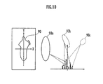
- the object discriminating portion 25, as illustrated in Fig. 10 performs Fourier transformation on the data of the contour 90 extracted from the image portion of the monitoring object, and calculates the Fourier pattern of the contour 90 according to the following mathematical expressions (93) to (95).
- the graph on the right side of Fig. 10 illustrates a Fourier pattern where the frequency is set as the lateral axis and the percentage of frequency is set as the vertical axis.
- Mathematical expression 93 K : z n x n + i ⁇ y n
- the object type discriminating portion 25 calculates a difference D min between the Fourier pattern 100a of the contour 100 of the monitoring object calculated accordingly and each of reference patterns 110a, 111a... of contours of pedestrians, namely the preset type of the monitoring object, according to the following mathematical expression (96).
- z(k),z(k-1) Data of the Fourier pattern of the contour of the image portion of the monitoring object
- z ref (k),z ref (k-1) Data of the reference pattern.
- the reference patterns 110a, 111a ... are Fourier patterns calculated on the basis of the contours of the posture patterns 110, 111 ... of the pedestrians, respectively.
- the object type discriminating portion 25 determines that the monitoring object is a pedestrian when the D min calculated according to the above mathematical expression (96) is equal to or smaller than a predefined threshold.
- the present invention is described to discriminate whether a monitoring object is a pedestrian or not in the present embodiment, it can be also used to discriminate whether a monitoring object is a large-sized animal, a vehicle or the like.
- the reference Fourier pattern is set in accordance with the type of the monitoring object to be discriminated.
- the object type discriminating portion 25 discriminates the type of the monitoring object according to the Fourier pattern of the contour; it is acceptable to discriminate the type of the monitoring object according to the other methods, such as pattern matching of contour shapes and extraction of a feature amount.
- the object detecting portion 20 detects an object on the basis of the distance measurement data by the laser radar, the image processing target area setting portion 21 sets the image processing target area on the basis of the detection result by the object detecting portion 20; it is also acceptable to configure the object detecting portion 20 as to detect an object according to an infrared image by the infrared camera 2.
- the object detecting portion 20 for example, detects the object on the basis of a binary image portion extracted according to a binary processing performed on the infrared image, and the image processing target area setting portion 21 sets the image processing target area according to the position of the detected object.
- the object detecting portion 20 detects an object on the basis of distance data of each of pixels in the image detected by, for example, a stereo camera, specifically, if pixels have almost equal distances, then those pixels belong to the object; and then the image processing target area setting portion 21 sets the image processing target area according to the position of the detected object.
- the orientation image is generated according to the directivity extraction processing performed by the directivity extracting portion 22 in STEP 5 of Fig. 3 .
- the present invention is adaptable even without the directivity extraction processing being performed.
- the contour extracting portion 24 extracts the contour of the image portion of the monitoring object by performing the convergence processing of the contour according to the luminance difference of the orientation image illustrated in Fig. 7 in STEP 8 of Fig. 3 and then the convergence processing of the contour according to the high speed Snakes algorithm.
- the infrared camera 2 is used as the imaging unit of the present invention. However, it is acceptable to use a common camera capable of detecting visible lights only.
- the present invention is configured to image the front side of the vehicle. However, it is acceptable to image another direction, such as the rear side, the lateral side or the like, and judge the contact probability to the monitoring object.
- the present invention is capable of reducing a throughput of extracting a contour of an image portion of a monitoring object contained in a captured image and shortening a time required for extracting the contour, therefore, it is usable in monitoring the periphery of a vehicle.
Landscapes
- Engineering & Computer Science (AREA)
- Theoretical Computer Science (AREA)
- Computer Vision & Pattern Recognition (AREA)
- Multimedia (AREA)
- General Physics & Mathematics (AREA)
- Physics & Mathematics (AREA)
- Evolutionary Computation (AREA)
- Mechanical Engineering (AREA)
- Software Systems (AREA)
- Artificial Intelligence (AREA)
- Medical Informatics (AREA)
- Databases & Information Systems (AREA)
- Computing Systems (AREA)
- Health & Medical Sciences (AREA)
- Data Mining & Analysis (AREA)
- General Health & Medical Sciences (AREA)
- Life Sciences & Earth Sciences (AREA)
- Bioinformatics & Computational Biology (AREA)
- Evolutionary Biology (AREA)
- General Engineering & Computer Science (AREA)
- Bioinformatics & Cheminformatics (AREA)
- Image Processing (AREA)
- Image Analysis (AREA)
- Closed-Circuit Television Systems (AREA)
Abstract
Description
- The present invention relates to a vehicle periphery motoring device which monitors a vehicle periphery by detecting a monitoring object located in the vehicle periphery according to a captured image by an imaging unit mounted in the vehicle, a vehicle periphery motoring program and a vehicle periphery motoring method.
- Conventionally, there has been known a vehicle periphery monitoring device (for example, refer to Japanese Patent No.
3515926 - Therefore, it has been considered to extract a contour of an image portion contained in a captured image by a camera mounted in a vehicle and discriminate a type of a monitoring object in a real space corresponding to the image portion according to the features of the contour, thereby to improve discrimination accuracy on discriminating the type of the monitoring object.
- However, since the throughput of a convergence computation for extracting the contour is enormous, it is necessary to use a computer of high performance. Thus, for a vehicle mounted with a computer of ordinary performance, it will take longer time to perform the contour extraction processing. Consequently, it is difficult to adopt the object-type discrimination based on the contour extraction in a vehicle periphery monitoring device in which real time processing is required.
- The present invention has been accomplished in view of the aforementioned problems, and it is therefore an object of the present invention to provide a vehicle periphery motoring, a vehicle periphery motoring program and a vehicle periphery motoring method capable of reducing a throughput in extracting a contour of an image portion of a monitoring object contained in a captured image to shorten a time required for extracting the contour.
- To attain an object of the present invention described above, the vehicle periphery monitoring device of the present invention is provided with an imaging unit mounted in a vehicle to image a periphery of the vehicle and is configured to monitor the periphery of the vehicle on the basis of a captured image by the imaging unit.
- The vehicle periphery monitoring device of the present invention includes an object detecting portion configured to detect an object located in an imaging area imaged by the imaging unit; an image processing target area setting portion configured to set an image processing target area which may include an image portion of a monitoring object in the captured image on the basis of a detection result from the obj ect detecting portion; a contour extracting portion configured to extract a contour of the image portion included in the image processing target area; and an object type discriminating portion configured to discriminate a type of the monitoring object in a real space corresponding to the image portion from which the contour has been extracted by the contour extracting portion on the basis of the extracted contour.
- According to the present invention, the image processing target area which may include the image portion of the monitoring object in the captured image is set by the image processing target area setting portion on the basis of the detection result from the object detecting portion. Then, the contour extracting portion extracts the contour of the image portion included in the image processing target area. According thereto, by limiting the image portion used for extracting the contour in the image processing target area, it is able to reduce the throughput of extracting the contour and shorten the time for extracting the contour in comparison with the case where the contour is extracted with respect to the whole captured image without any limitations.
- The object type discriminating portion discriminates whether or not the type of the monitoring object in the real space corresponding to the image portion from which the contour has been extracted is a predefined type by comparing a frequency component of the contour extracted by the contour extracting portion with a comparison pattern of frequency components set according to the monitoring object of the predefined type.
- According to the present invention, whether the type of the monitoring object in the real space corresponding to the image portion where the contour has been extracted is a predefined type can be discriminated by using the frequency component of the contour as a characteristic index value for the predefined type of the monitoring object.
- The present invention further includes a directivity extracting portion configured to perform a directivity extraction processing which performs a differential filtering on each of pixels in the image processing target area in a predefined direction, allocates a predefined first luminance to a pixel whose directivity has been recognized by the differential filtering and allocates a second luminance having a difference of not smaller than a predefined level compared with the first luminance to a pixel whose directivity is not recognized, wherein the contour extracting portion extracts the contour of the image portion in the image processing target area where the directivity extraction processing has been performed.
- According to the present invention, by performing the directivity extraction processing with respect to the image processing target area, the luminance difference between the axils with directivity and the axils without directivity can be further differentiated, as a result thereof, it is possible to obtain the image portion with the contour thereof emphasized from the image processing target area. Thereafter, the contour of the image portion in the image processing target area on which the directivity extraction processing has been performed is extracted by the contour extracting portion. Consequently, the extraction accuracy for extracting the contour can be improved.
- The contour extracting portion extracts the contour of the image portion by setting an initial eclipse circling the image portion in the image processing target area where the directivity extraction processing has been performed and scaling down the circumference of the initial ellipse inward to a position of a pixel which has a luminance equal to a threshold set between the first luminance and the second luminance.
- According to the present invention, the contour of the image portion can be extracted by scaling down the circumference of the initial ellipse inward close to the contour of the image portion whose contour has been emphasized by the directivity extraction processing.
- The contour extracting portion extracts the contour of the image portion by setting an initial eclipse circling the image portion in the image processing target area and performing a contour convergence processing on the initial ellipse according to Snakes algorithm, the contour convergence processing is performed according to the Snakes algorithm by using a computation expression in which a multiplication term of an internal energy of Snakes energy where the Snakes energy and a contour positional variation and an external energy variation and an internal energy variation are presumed to be of zero at the time when a contour of a Snakes model of a discrete system is converged is multiplied to a multiplication term of the external energy.
- According to the present invention, the contour extracting portion performs the contour convergence processing by using the computation expression in which a multiplication term of an internal energy of Snakes energy where the Snakes energy and a contour positional variation and an external energy variation and an internal energy variation are presumed to be of zero at the time when a contour of a Snakes model of a discrete system is converged is multiplied to a multiplication term of the external energy. According thereto, it is able to reduce the throughput of the contour convergence processing by the Snakes algorithm and therefore shorten the time for extracting the contour, which will be described again hereinafter.
- The contour extracting portion sets an initial eclipse circling the image portion in the image processing target area where the directivity extraction processing has been performed, and extracts a contour of the image portion by scaling down the circumference of the initial ellipse inward to a position of a pixel which has a luminance equal to a threshold set between the first luminance and the second luminance; the extracted contour is further converged by a contour convergence processing performed thereon according to Snakes algorithm; and the contour convergence processing is performed according to the Snakes algorithm by using a computation expression in which a multiplication term of an internal energy of Snakes energy where the Snakes energy and a contour positional variation and an external energy variation and an internal energy variation are presumed to be of zero at the time when a contour of a Snakes model of a discrete system is converged is multiplied to a multiplication term of the external energy.
- According to the present invention, the initial ellipse circling the image portion in the image processing target area on which the directivity extraction processing has been performed is set and the contour is extracted by the contour extracting portion, and the extracted contour is further converged by a contour convergence processing performed thereon according to Snakes algorithm, it is possible to shorten the time needed by the contour convergence processing, and therefore, the extraction accuracy for extracting the contour can be improved.
- The contour extracting portion uses the following mathematical expressions (6) and (7) as the computation expression:

Herein, - (xt, yt): coordinate of a contour dot at timing t;
- (xt-1, yt-1) : a model expression of the contour at timing t-1;
- I: a unit matrix;
- A: a transform matrix of internal energy:
- γ: an iteration step (moving amount of the contour per step when converging it inward);
- fx: a computation expression of x components of the external energy; and
- fy: a computation expression of y components of the external energy.
- According to the present invention, it is possible for the contour extracting portion to reduce the throughput needed to perform the contour convergence processing according to Snake algorithm and shorten the extraction time for extracting the contour by using the mathematical expressions (6) and (7).
- The iteration step γ in the mathematical expressions (6) and (7) is configured to satisfy the following conditions defined by the mathematical expression (10) for the following mathematical expression (9) which is a Snakes expression where the discrete model of the contour is defined according to the following mathematical expression (8):

Herein, Ki: discrete model of the contour
Herein, - E: Snakes expression;
- Eint(Ki): Internal energy:
- Eext(Ki): External energy:
- α, β: computation coefficients.
- According to the present invention, which will be described hereinafter, by configuring the iteration step γ to satisfy the conditions defined by the mathematical expression (10), it is possible for the contour extracting portion to perform stably the contour convergence processing according to the mathematical expressions (6) and (7).
- The present invention further includes a radar, which is mounted in the vehicle, configured to detect a distance between the vehicle and the object located in the imaging area imaged by the imaging unit, wherein the obj ect detecting portion detects the object located in the imaging area according to the distance detected by the radar.
- According to the present invention, the object detecting portion can detect the object located in a range of a predefined distance from the vehicle according to the distance detected by the radar. Then, the area containing the image portion of the object can be set by the image processing target area setting portion as the image processing target area.
- A vehicle periphery monitoring program of the present invention causes a computer provided with an accessing portion configured to access a captured image by an imaging unit which is mounted in a vehicle to image a periphery of the vehicle to monitor the periphery of the vehicle on the basis of the captured image by the imaging unit.
- The program functions the computer as an object detecting portion configured to detect an object located in an imaging area imaged by the imaging unit; an image processing target area setting portion configured to set an image processing target area which may include an image portion of a monitoring object in the captured image on the basis of a detection result from the object detecting portion; a contour extracting portion configured to extract a contour of the image portion included in the image processing target area; and an object type discriminating portion configured to discriminate a type of the monitoring object in a real space corresponding to the image portion from which the contour has been extracted by the contour extracting portion on the basis of the extracted contour.
- By executing the vehicle periphery monitoring program of the present invention in the computer, the object detecting portion, the image processing target area setting portion, the contour extracting portion and the object type discriminating portion in the vehicle periphery monitoring device of the present invention as described above can be constituted.
- A vehicle periphery monitoring method of the present invention monitors a periphery of a vehicle according to a computer provided with an accessing portion configured to access a captured image by an imaging unit which is mounted in the vehicle to image the periphery of the vehicle to monitor the periphery of the vehicle on the basis of the captured image by the imaging unit.
- The vehicle periphery monitoring method of the present invention includes an object detecting step in which the computer detects an object located in an imaging area imaged by the imaging unit; an image processing target area setting step in which the computer sets an image processing target area which may include an image portion of a monitoring object in the captured image on the basis of a detection result from the object detecting step; a contour extracting step in which the computer extracts a contour of the image portion included in the image processing target area; and an object type discriminating step in which the computer discriminates a type of the monitoring object in a real space corresponding to the image portion from which the contour has been extracted by the contour extracting step on the basis of the extracted contour.
- According to the present invention, in the image processing target area setting step, the computer sets the image processing target area which may include the image portion of the monitoring object in the captured image on the basis of the detection result from the object detecting step. In the contour extracting step, the computer extracts the contour of the image portion included in the image processing target area. According thereto, by limiting the image portion used for extracting the contour in the image processing target area, it is able to reduce the throughput of extracting the contour and shorten the time for extracting the contour in comparison with the case where the contour is extracted with respect to the whole captured image without limitation.
-
-
Fig. 1 is a block diagram of a vehicle periphery monitoring device of the present invention. -
Fig. 2 is an explanatory diagram illustrating an assembled state of the vehicle periphery monitoring device inFig. 1 to a vehicle. -
Fig. 3 is a flow chart illustrating a pedestrian discriminating process of the present invention. -
Fig. 4 is an explanatory diagram illustrating a setting processing of an image processing target area on the basis of a distance measurement data of a monitoring object by radar. -
Fig. 5 is an explanatory diagram illustrating behaviors of textured- parts in the image portion. -
Fig. 6 is an explanatory diagram illustrating orientation images. -
Fig. 7 is an explanatory diagram illustrating a contour extraction processing. -
Fig. 8 is an explanatory diagram illustrating a contour extraction processing. -
Fig. 9(a) and Fig. 9(b) are explanatory diagrams illustrating an internal energy and an external energy according to Snakes algorithm. -
Fig. 10 is an explanatory diagram illustrating Fourier transformation on the contour data. -
Fig. 11 is an explanatory diagram illustrating discrimination of a pedestrian according to Fourier patterns of the contour. - Hereinafter, an embodiment of the present invention will be described in detail with reference to
Fig. 1 to Fig. 11 .Fig. 1 is a block diagram of a vehicle periphery monitoring device of the present invention. The vehicle periphery monitoring device of the present invention is provided with animage processing unit 1, aninfrared camera 2 capable of detecting far infrared rays (equivalent to an imaging unit of the present invention), alaser radar 8 configured to radiate laser rays on an object and detect a distance between the object and a vehicle (equivalent to a radar of the present invention), ayaw rate sensor 3 configured to detect a yaw rate of the vehicle, and avehicular velocity sensor 4 configured to detect a driving velocity of the vehicle. - The
image processing unit 1 discriminates a type of a monitoring object (a pedestrian, an animal or the like) in front of the vehicle from a captured image by theinfrared camera 2, and outputs an alarm when there is a high possibility of contact between the monitoring object and the vehicle. Thereby, the vehicle periphery monitoring device includes a speaker 6 for playing an alarm sound, and a head-up display (hereinafter, referred to as HUD) 7 for displaying visually the monitoring object to a driver. - Hereinafter, with reference to
Fig. 2 , an assembled state of the vehicle periphery monitoring device to the vehicle will be described. Thelaser radar 8 is of a two dimensional scanning type and is disposed in a front portion of thevehicle 10. The laser radar scans a first monitoring range preliminarily set in front (moving direction of the vehicle 10) along a horizontal direction and a vertical direction. - The
infrared camera 2 has such a property that when a temperature of a captured object becomes higher, an output level thereof will be higher (a luminance thereof will become greater). Theinfrared camera 2 is disposed in a front portion of thevehicle 10 and images a second monitoring-range (defined inside the above-mentioned first monitoring range) preliminarily set in front. The HUD 7 is disposed to display apicture area 7a on a windshield in a front position of the driver's side. - The
image processing unit 1 includes an image inputting circuit configured to convert an analogue image signal output from theinfrared camera 2 to a digital data and introduce it to an image memory, an interface circuit (corresponding to an accessing portion to access a captured image by the imaging portion of the present invention) configured to access (read and write) the image data introduced to the image memory, and an interface circuit configured to input a distance detection signal from thelaser radar 8. - The
image processing unit 1 is an electronic unit provided with a computer (an arithmetic processing circuit composed of a CPU, a memory, an input circuit, an output circuit and the like, or a micro computer integrated with these functions) or the like which performs various arithmetic computations on the image data introduced into the image memory. - By causing the computer to execute a vehicle periphery monitoring program of the present invention, the computer functions as an
object detecting portion 20 configured to detect an object located in the first monitoring range on the basis of detected distance signals from thelaser radar 8, an image processing targetarea setting portion 21 configured to set an image processing target -area which may include an image portion of the monitoring object, adirectivity extracting portion 22 configured to perform a directivity extraction processing which extracts directivity (orientation) of each pixel in the image processing target area, an image processing targetarea correcting portion 23 configured to correct a range of the image processing target area after the directivity extraction processing has been performed thereon, acontour extracting portion 24 configured to extract a contour of the image portion included in the image processing target area, and an objecttype discriminating portion 25 configured to discriminate a type of the monitoring object in a real space corresponding to the image portion from which the contour has been extracted by thecontour extracting portion 24 on the basis of the extracted contour. In the present embodiment, the objecttype discriminating portion 25 discriminates whether the monitoring object is a pedestrian or not. - Owning to these portions, an object detecting step, an image processing target area setting step; a contour extracting step, and an object type discriminating step in a vehicle periphery monitoring method of the present invention are executed.
- A discrimination method for a type of a monitoring object by the
image processing unit 1 in an embodiment of the present invention will be described hereinafter with reference to the flow chart illustrated inFig. 3 . - First, -the
image processing unit 1 performs processing inSTEP 1,STEP 20 and STEP 30 in parallel. InSTEP 1, theimage processing unit 1 retrieves outputs from thevehicular velocity sensor 4 and theyaw rate sensor 3 and calculates a turning angle of thevehicle 10. InSTEP 20, theimage processing unit 1 is input with a distance measurement data of the first monitoring range from thelaser radar 8 and detects an object located in the first monitoring range. - In STEP 30, the
image processing unit 1 is input with an infrared image from theinfrared camera 2. Note that, inSTEP 20, the detection processing for detecting an object located in the first monitoring range is equivalent to the object detecting step of the present invention. - Subsequently in
STEP 2, theimage processing unit 1 performs docking of the monitoring object located in the first monitoring range while correcting the turning angle on the basis of the distance measurement data from thelaser radar 8. The processing inSTEP 3 and the processing inSTEP 4 are performed by the image processing targetarea setting portion 20. The image processing targetarea setting portion 20 estimates an intersection point between the monitoring object and the road surface inSTEP 3, and sets the image processing target area by taking the intersection point as a reference inSTEP 4. The process of setting the image processing target area inSTEP 4 corresponds to the image processing target area setting step of the present invention. -
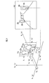
Fig. 4 illustrates a method of setting the image processing target area in the infrared image captured by thecamera 2 on the basis of the distance measurement data from thelaser radar 8 and a physical data of the pedestrian. The left side ofFig. 4 illustrates a situation where the distances to the monitoring objects (pedestrians in the present embodiment) 52a and 54a in front of thevehicle 10 are measured respectively at a timing tk in a real space having the moving direction of thevehicle 10 as Vz, the vertical direction as Vy and the vehicular width direction as Vx. The right side ofFig. 4 illustrates a captured image Im1 by theinfrared camera 2 at the timing tk. - Referring to
Fig. 4 , the distance Vz1(tk) between thepedestrian 52a and thevehicle 10, and the distance Vz2(tk) between thepedestrian 54a and thevehicle 10 are measured. With respect to thepedestrian 52a, the image processing targetarea setting portion 20 scales therange 51a (Vb1(tk) x Vh1(tk)), which is defined according to the physical data of a pedestrian (which is set relatively greater than a general pedestrian and is pre-stored in a memory (not shown) and corresponds to a size data of an object of the present invention) with the intersection point between thepedestrian 52a and the road surface as the reference, down to the imageprocessing target area 51b on the basis of the distance Vz1(tk) between thepedestrian 52a and thevehicle 10, and sets it on the captured image Im1. - Similarly, with respect to the
monitoring object 54a, the image processing targetarea setting portion 20 scales therange 53a (Vb2(tk) × Vh2(tk)), which is defined according to the physical data of a pedestrian with the intersection point between themonitoring object 54a and the road surface as the reference, down to the imageprocessing target area 53b on the basis of the distance Vz2(tk) between themonitoring object 54a and thevehicle 10, and sets it on the captured image Im1. - Thereby, by setting the image
processing target area 51b for themonitoring object 52a and the imageprocessing target area 53b for themonitoring obj ect 54a on the basis of the physical data of the pedestrians with the intersection point to the road surface as the reference, the imageprocessing target area 51b can be set to include the total part of theimage portion 52b of themonitoring object 52a and the imageprocessing target area 53b can be set to include the total part of theimage portion 54b of themonitoring object 54a. - The subsequent STEP 5 is perpormed by the
directivity extracting portion 22. Thedirectivity extracting portion 22 calculates the matrix Jpq(X) through a differential filtering expressed by the following mathematical expression (11) for each pixel in the image processing target area.


- Then, the eigenvalue λ of the matrix Jpq(X) can be calculated out from the mathematical expression (16) according to the following mathematical expressions (17) to (23).

Herein,υ : Engenvector, λ: Engenvalue





- From the above expressions (22) and (23), the relation according to the following mathematical expression (24) can be obtained.

- The engenvalues J11' and J22' vary according to textures of the image (patterns according to the luminance variation). In other words, as illustrated in
Fig. 5 , the engenvalues J11' and J22' vary as follows if the captured image Im2 contains aportion 60a having isotropy (with irregular variation patterns), aportion 60b having directivity (with iterative patterns in a defined direction) and aportion 60c having homogeneity (with no pattern). -


-


-


- Thus, as illustrated in
Fig. 6 , thedirectivity extracting portion 22 performs the differential filtering expressed by the mathematical expression (11) above on an image processing target area Im3 set by the image processing targetarea setting portion 21 and determines whether or not the conditions of the above (1) to (3) hold. Thedirectivity extracting portion 22 performs the directivity extraction processing for generating an orientation image Im4 in which the luminance of pixels in the portion having homogeneity is set at zero (corresponding to a first luminance of the present invention), the luminance of pixels in the portion having directivity is set at a predefined luminance (corresponding to a second luminance of the present invention), and the luminance of pixels in the portion having isotropy is set lower than the luminance of pixels in the portion having directivity. According to the directivity extraction processing, the contour portion of the image portion contained in the image processing target area Im3 is emphasized and the orientation image Im4 can be obtained. Note that a level of the predefined luminance is equivalent to a predefined level of the present invention. - The processing in STEP 6 is performed by the image processing target
area correcting portion 23. The image processing targetarea correcting portion 23 searches a feature region having a feature amount corresponding to a head of the monitoring obj ect, namely a pedestrian, in the image processing target area. If the feature region is detected, the image processing targetarea correcting portion 23 corrects the position of the image processing target area so as to locate the image portion in the central part of the image processing target area. - The processing in the subsequent STEP 7 and
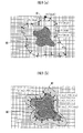
STEP 8 is performed by thecontour extracting portion 24. As illustrated by Im5 ofFig. 7 , thecontour extracting portion 24 sets aninitial ellipse 72 on theorientation image 70 which is generated by performing the above-mentioned directivity extraction processing in the image processing target area. In thenext STEP 8, thecontour extracting portion 24 performs convergence processing on theinitial ellipse 72 by converging it toward the center, as illustrated by theenclosed line 73 in Im6. - Specifically, as illustrated in
Fig. 8 , thecontour extracting portion 24 causes theinitial ellipse 72 to converge by moving each point of theinitial ellipse 72 to a position Pe where the luminance is of a threshold value Yth. Accordingly, as illustrated by Im7 ofFig. 7 , acontour 74 of the image portion of the monitoring object can be obtained. - Thereafter, the
contour extracting portion 24 performs a convergence computation processing according to Snakes algorithm and further makes thecontour 74 converge. In general, the Snakes algorithm obtains a contour of a subject by minimizing a sum of an internal energy of the contour (length/ shape of the contour) and an external energy thereof (luminance/ luminance gradient) according to the mathematical expression (31).
- Herein, Eintern: Internal energy of the contour; Eextern: External energy of the contour.
- As illustrated in
Fig. 9(a) , the internal energy of the contour is a force drawing thecontour 81 inward (toward theobject 80 of which the contour is to be extracted) and is expressed by the mathematical expression (32).
- As illustrated in
Fig. 9(b) , the external energy of the contour is a force pushing thecontour 82 outward (leaving away from theobject 80 of which the contour is to be extracted) and is expressed by the mathematical expression (33).
- Herein, I(νi): Luminance; ∇I(νi): Luminance gradient
- If a continuous model of contour is defined according to the following mathematical expression (34), then the Snakes expression (31) can be expressed by the following mathematical expression (35).


- If using the following mathematical expressions (36) and (37) to express the Snakes expression, it can be expressed by the following mathematical expression (38).


- The following mathematical expressions (40) and (41) can be deduced by using Euler-Lagrange theorem on the following mathematical expression (39).


- A discrete model of contour is defined by the following mathematical expression (42), and it can be expressed by the following mathematical expression (43) if the finite difference method is used by setting E=0.


- When the initial ellipse has been converged to the contour of the object, if the iteration step (step size when moving the contour inward) is set to γ, then the Snakes energy (= the internal energy+ the external energy), the positional variation of the contour and the variation of the external energy become zero. Therefore, the relations according to the following mathematical expressions (54) to (56) hold.


- From the above mathematical expressions (54) to (56), the relationship expressed by the following mathematical expression (57) can be obtained.

- If the above mathematical expression is expressed in explicit formula, it has the forms represented by the following mathematical expressions (58) to (60), therefore, it is necessary to do multiplication computations for 2n2 times and addition computations for 2n(n-1) times by a total of x and y in the convergence computation of the contour.


- Thereby, the contour extracting portion reduces the throughput of the contour convergence processing so as to shorten the time needed to extract the contour according to the algorithm (hereinafter, referred to as high speed Snakes) to be described below.
- If the Snakes energy, the positional variation of the contour, the external energy variation and the internal energy variation at the convergence of contour in the Snakes model is set at zero, respectively, then the following mathematical expressions (61) to (64) hold.


- Accordingly, the following mathematical expression (65) is obtained. If the mathematical expression (65) is expressed in explicit formula, the following mathematical expressions (66) to (68) can be obtained.


- If the above-mentioned mathematical expressions (67) and (68) are transformed into a form in which (I-γA) multiplies the external energy, they can be expressed by the mathematical expressions (69) and (70), respectively.


- Thereby, the mathematical expressions (69) and (70) can be expressed in the following mathematical expressions (71) to (75), the contour can be converged by multiplication computations for 6n times and addition computations for 8n times by the total of x and y.


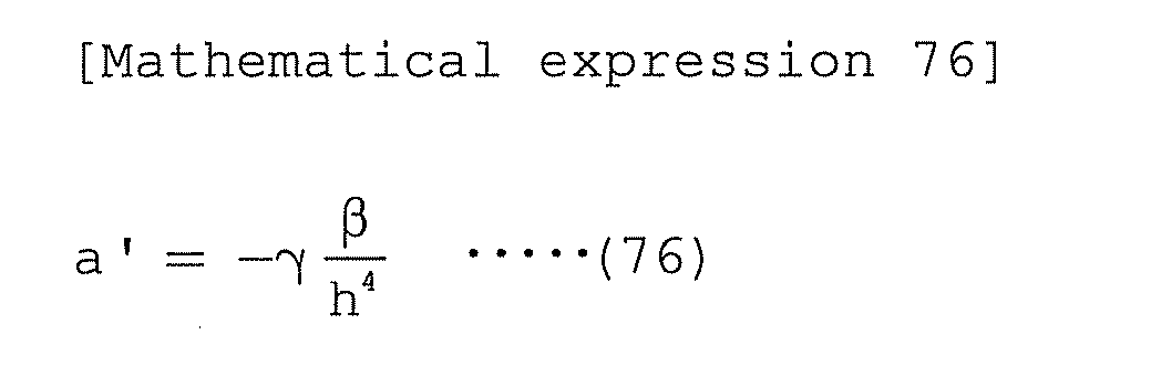


- Therefore, by using the high speed Snakes, it is possible to reduce the throughput from (multiplication computations for 2n2 times and addition computations for 2n(n-1) times) when the common Snakes algorithm is used to (multiplication computation for 6n times and addition computations for 8n times). Thereby, even for a vehicular computer with a low performance, it is possible to discriminate the type of the monitoring object by using the contour extraction processing.
- However, in order to make the contour converge steadily, it is necessary for (I-γA) to be a smoothing filter. Thus, as illustrated by the following mathematical expression (79), the filter gain F(s) should not be greater than 1.

- Herein, F̂(S̃): Expression denoting the filter gain in a frequency band region.
- Since the above-mentioned matrix A is expressed by the differential filters of second order and fourth order according to the mathematical expressions (43) and (44), the smoothing term (I-γA) can be denoted by (I-κDp) (D: derivative filter, p represents an order), thereby, the condition where (I-κDp) becomes the smoothing filter is defined by the mathematical expression (80).
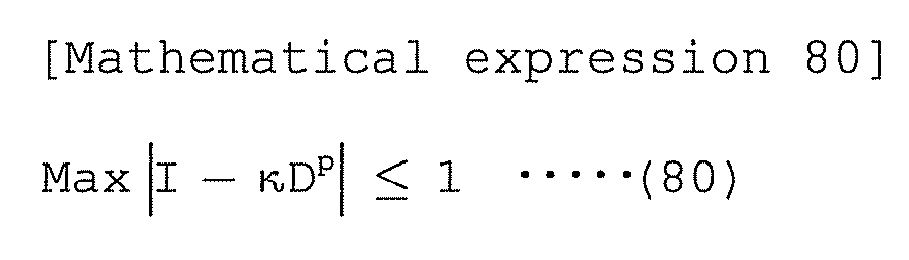
- Here, the differential filter [1, -1] becomes 2i sin (πS̃ / 2) if represented by the frequency region, and Dp is expressed by the following mathematical expression (81). Therefore, the condition defined by the following mathematical expression (82) must be satisfied.


- In the mathematical expression (82) above, the left side thereof becomes maximum as S̃=1, then, the above mathematical expression (82) can be transformed into the following mathematical expression (83).

- Take squire both sides of the mathematical expression (83), and resolve k on a condition that p is an even number since the matrix A is expressed by the differential filter of the second and fourth order, then the following mathematical expressions (84) to '(86) hold.


- The actual (I-γA) can be denoted as the following mathematical expression (87) from the above-mentioned mathematical expressions (43) and (44). Accordingly, the mathematical expressions (84) to (86) hold the forms denoted by the following mathematical expressions (87) to (91).
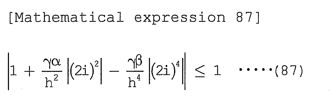


- Thus, by setting the iteration step γ satisfying the condition defined by the mathematical expression (92) above, it is possible to make the contour converge steadily. Note that the contour extraction processing for extracting the contour of the image portion of the monitoring object in STEP 7 and
STEP 8 is equivalent to the contour extracting step of the present invention. - Subsequent STEP 9 and
STEP 10 inFig. 3 are performed by the objecttype discriminating portion 25. In STEP 9, theobject discriminating portion 25, as illustrated inFig. 10 , performs Fourier transformation on the data of thecontour 90 extracted from the image portion of the monitoring object, and calculates the Fourier pattern of thecontour 90 according to the following mathematical expressions (93) to (95). The graph on the right side ofFig. 10 illustrates a Fourier pattern where the frequency is set as the lateral axis and the percentage of frequency is set as the vertical axis.
- Herein, K: data of the contour


- Then, as illustrated in
Fig. 11 , the objecttype discriminating portion 25 calculates a difference Dmin between theFourier pattern 100a of thecontour 100 of the monitoring object calculated accordingly and each ofreference patterns 110a, 111a... of contours of pedestrians, namely the preset type of the monitoring object, according to the following mathematical expression (96).
- Herein, z(k),z(k-1): Data of the Fourier pattern of the contour of the image portion of the monitoring object; zref(k),zref(k-1): Data of the reference pattern.
- The
reference patterns 110a, 111a ... are Fourier patterns calculated on the basis of the contours of theposture patterns type discriminating portion 25 determines that the monitoring object is a pedestrian when the Dmin calculated according to the above mathematical expression (96) is equal to or smaller than a predefined threshold. - The process of discriminating the type of the monitoring object in STEP 9 and
STEP 10 is equivalent to the object type discriminating step of the present invention. - The present invention is described to discriminate whether a monitoring object is a pedestrian or not in the present embodiment, it can be also used to discriminate whether a monitoring object is a large-sized animal, a vehicle or the like. In this case, the reference Fourier pattern is set in accordance with the type of the monitoring object to be discriminated.
- In the present embodiment, the object
type discriminating portion 25 discriminates the type of the monitoring object according to the Fourier pattern of the contour; it is acceptable to discriminate the type of the monitoring object according to the other methods, such as pattern matching of contour shapes and extraction of a feature amount. - In the present embodiment, the
object detecting portion 20 detects an object on the basis of the distance measurement data by the laser radar, the image processing targetarea setting portion 21 sets the image processing target area on the basis of the detection result by theobject detecting portion 20; it is also acceptable to configure theobject detecting portion 20 as to detect an object according to an infrared image by theinfrared camera 2. In this case, theobject detecting portion 20, for example, detects the object on the basis of a binary image portion extracted according to a binary processing performed on the infrared image, and the image processing targetarea setting portion 21 sets the image processing target area according to the position of the detected object. If a visible camera is used, it is acceptable that theobject detecting portion 20 detects an object on the basis of distance data of each of pixels in the image detected by, for example, a stereo camera, specifically, if pixels have almost equal distances, then those pixels belong to the object; and then the image processing targetarea setting portion 21 sets the image processing target area according to the position of the detected object. - In the present embodiment, the orientation image is generated according to the directivity extraction processing performed by the
directivity extracting portion 22 in STEP 5 ofFig. 3 . However, the present invention is adaptable even without the directivity extraction processing being performed. - In the present embodiment, the
contour extracting portion 24 extracts the contour of the image portion of the monitoring object by performing the convergence processing of the contour according to the luminance difference of the orientation image illustrated inFig. 7 inSTEP 8 ofFig. 3 and then the convergence processing of the contour according to the high speed Snakes algorithm. However, it is acceptable to fulfill the present invention by performing the convergence processing of the contour according to the luminance difference of the orientation image only, or performing the convergence processing of the contour according to the high speed Snakes algorithm only. - In the present embodiment, the
infrared camera 2 is used as the imaging unit of the present invention. However, it is acceptable to use a common camera capable of detecting visible lights only. - In the present embodiment, the present invention is configured to image the front side of the vehicle. However, it is acceptable to image another direction, such as the rear side, the lateral side or the like, and judge the contact probability to the monitoring object.
- As above-mentioned, the present invention is capable of reducing a throughput of extracting a contour of an image portion of a monitoring object contained in a captured image and shortening a time required for extracting the contour, therefore, it is usable in monitoring the periphery of a vehicle.

Claims (11)
- A vehicle periphery monitoring device which is provided with an imaging unit mounted in a vehicle to image a periphery of the vehicle and is configured to monitor the periphery of the vehicle on the basis of a captured image by the imaging unit, comprising:an object detecting portion configured to detect an object located in an imaging area imaged by the imaging unit;an image processing target area setting portion configured to set an image processing target area which may include an image portion of a monitoring object in the captured image on the basis of a detection result from the object detecting portion;a contour extracting portion configured to extract a contour of the image portion included in the image processing target area; andan object type discriminating portion configured to discriminate a type of the monitoring object in a real space corresponding to the image portion from which the contour has been extracted by the contour extracting portion on the basis of the extracted contour.
- The vehicle periphery monitoring device according to claim 1, wherein
the object type discriminating portion discriminates whether or not the type of the monitoring object in the real space corresponding to the image portion from which the contour has been extracted is a predefined type by comparing a frequency component of the contour extracted by the contour extracting portion with a comparison pattern of frequency components set according to the monitoring object of the predefined type. - The vehicle periphery monitoring device according to claim 1 or claim 2, further includes a directivity extracting portion configured to perform a directivity extraction processing which performs a differential filtering on each of pixels in the image processing target area in a predefined direction, allocates a predefined first luminance to a pixel whose directivity has been recognized by the differential filtering, and allocates a second luminance having a difference of not smaller than a predefined level compared with the first luminance to a pixel whose directivity is not recognized,
wherein the contour extracting portion extracts the contour of the image portion in the image processing target area where the directivity extraction processing has been performed. - The vehicle periphery monitoring device according to claim 3, wherein the contour extracting portion extracts the contour of the image portion by setting an initial eclipse circling the image portion in the image processing target area where the directivity extraction processing has been performed and scaling down the circumference of the initial ellipse inward to a position of a pixel which has a luminance equal to a threshold set between the first luminance and the second luminance.
- The vehicle periphery monitoring device according to any of claims 1 to 3, wherein
the contour extracting portion extracts the contour of the image portion by setting an initial eclipse circling the image portion in the image processing target area and performing a contour convergence processing on the initial ellipse according to Snakes algorithm,
the contour convergence processing is performed according to the Snakes algorithm by using a computation expression in which a multiplication term of an internal energy of Snakes energy where the Snakes energy and a contour positional variation and an external energy variation and an internal energy variation are presumed to be of zero at the time when a contour of a Snakes model of a discrete system is converged is multiplied to a multiplication term of the external energy. - The vehicle periphery monitoring device according to claim 3, wherein
the contour extracting portion sets an initial eclipse circling the image portion in the image processing target area where the directivity extraction processing has been performed, and extracts a contour of the image portion by scaling down the circumference of the initial ellipse inward to a position of a pixel which has a luminance equal to a threshold set between the first luminance and the second luminance;
the extracted contour is further converged by a contour convergence processing performed thereon according to Snakes algorithm; and
the contour convergence processing is performed according to the Snakes algorithm by using a computation expression in which a multiplication term of an internal energy of Snakes energy where the Snakes energy and a contour positional variation and an external energy variation and an internal energy variation are presumed to be of zero at the time when a contour of a Snakes model of a discrete system is converged is multiplied to a multiplication term of the external energy. - The vehicle periphery monitoring device according to claim 5 or 6, wherein
the contour extracting portion uses the following mathematical expressions (1) and (2) as the computation expression:

Herein,(xt, yt): coordinate of a contour dot at timing t;(xt-1, yt-1) : a model expression of the contour at timing t-1;I: a unit matrix;A: a transform matrix of internal energy:γ: an iteration step (moving amount of the contour per step when converged inward);fx: a computation expression of x components of the external energy; andfy: a computation expression of y components of the external energy. - The vehicle periphery monitoring device according to claim 7, wherein
the iteration step γ in the mathematical expressions (1) and (2) is configured to satisfy the following conditions defined by the mathematical expression (5) for the following mathematical expression (4) which is a Snakes expression where the discrete model of the contour is defined according to the following mathematical expression (3):
Herein, Ki: discrete model of the contour
Herein,E: Snakes expression;Eint(Ki) : Internal energy:Eext(Ki) : External energy:α, β: computation coefficients.
- The vehicle periphery monitoring device according to any of claims 1 to 8, further includes a radar configured to detect a distance between the vehicle and the object located in the imaging area imaged by the imaging unit,
wherein the object detecting portion detects the object located in the imaging area according to the distance detected by the radar. - A vehicle periphery monitoring program which causes a computer provided with an accessing portion configured to access a captured image by an imaging unit which is mounted in a vehicle to image a periphery of the vehicle to monitor the periphery of the vehicle on the basis of the captured image by the imaging unit, the program functioning the computer as:an object detecting portion configured to detect an object located in an imaging area imaged by the imaging unit;an image processing target area setting portion configured to set an image processing target area which may include an image portion of a monitoring object in the captured image on the basis of a detection result from the object detecting portion;a contour extracting portion configured to extract a contour of the image portion included in the image processing target area; andan object type discriminating portion configured to discriminate a type of the monitoring object in a real space corresponding to the image portion from which the contour has been extracted by the contour extracting portion on the basis of the extracted contour.
- A vehicle periphery monitoring method which monitors a periphery of a vehicle according to a computer provided with an accessing portion configured to access a captured image by an imaging unit which is mounted in the vehicle to image the periphery of the vehicle to monitor the periphery of the vehicle on the basis of the captured image by the imaging unit, comprising steps of:an object detecting step in which the computer detects an object located in an imaging area imaged by the imaging unit;an image processing target area setting step in which the computer sets an image processing target area which may include an image portion of a monitoring object in the captured image on the basis of a detection result from the object detecting step;a contour extracting step in which the computer extracts a contour of the image portion included in the image processing target area; andan object type discriminating step in which the computer discriminates a type of the monitoring object in a real space corresponding to the image portion from which the contour has been extracted by the contour extracting step on the basis of the extracted contour.
Applications Claiming Priority (1)
| Application Number | Priority Date | Filing Date | Title |
|---|---|---|---|
| PCT/JP2007/059224 WO2008139530A1 (en) | 2007-04-27 | 2007-04-27 | Vehicle periphery monitoring device, vehicle periphery monitoring program, and vehicle periphery monitoring method |
Publications (2)
| Publication Number | Publication Date |
|---|---|
| EP2141926A1 true EP2141926A1 (en) | 2010-01-06 |
| EP2141926A4 EP2141926A4 (en) | 2010-08-11 |
Family
ID=40001766
Family Applications (1)
| Application Number | Title | Priority Date | Filing Date |
|---|---|---|---|
| EP07742659A Withdrawn EP2141926A4 (en) | 2007-04-27 | 2007-04-27 | Vehicle periphery monitoring device, vehicle periphery monitoring program, and vehicle periphery monitoring method |
Country Status (4)
| Country | Link |
|---|---|
| US (1) | US8411145B2 (en) |
| EP (1) | EP2141926A4 (en) |
| JP (1) | JP5145599B2 (en) |
| WO (1) | WO2008139530A1 (en) |
Cited By (4)
| Publication number | Priority date | Publication date | Assignee | Title |
|---|---|---|---|---|
| CN102713989A (en) * | 2010-03-17 | 2012-10-03 | 本田技研工业株式会社 | Vehicle Surrounding Monitoring Device |
| CN103098097A (en) * | 2010-09-15 | 2013-05-08 | 丰田自动车株式会社 | Surrounding image display system and surrounding image display method for vehicle |
| EP2921992A3 (en) * | 2014-03-18 | 2015-09-30 | Ricoh Company, Ltd. | Image processing device, drive support system, image processing method, and program |
| EP3666594A1 (en) * | 2018-12-12 | 2020-06-17 | Ningbo Geely Automobile Research & Development Co. Ltd. | System and method for warning a driver of a vehicle of an object in a proximity of the vehicle |
Families Citing this family (24)
| Publication number | Priority date | Publication date | Assignee | Title |
|---|---|---|---|---|
| JP5036611B2 (en) * | 2008-03-27 | 2012-09-26 | ダイハツ工業株式会社 | Image recognition device |
| JP4766402B2 (en) * | 2008-10-21 | 2011-09-07 | トヨタ自動車株式会社 | Radar equipment |
| JP5401257B2 (en) * | 2009-10-23 | 2014-01-29 | クラリオン株式会社 | Far-infrared pedestrian detection device |
| KR101395089B1 (en) * | 2010-10-01 | 2014-05-16 | 안동대학교 산학협력단 | System and method for detecting obstacle applying to vehicle |
| EP2827318A4 (en) * | 2012-03-12 | 2016-01-13 | Honda Motor Co Ltd | DEVICE FOR MONITORING VEHICLE PERIPHERY |
| JP5666538B2 (en) * | 2012-11-09 | 2015-02-12 | 富士重工業株式会社 | Outside environment recognition device |
| EP2972478B1 (en) | 2013-03-15 | 2020-12-16 | Uatc, Llc | Methods, systems, and apparatus for multi-sensory stereo vision for robotics |
| US9070023B2 (en) * | 2013-09-23 | 2015-06-30 | Toyota Motor Engineering & Manufacturing North America, Inc. | System and method of alerting a driver that visual perception of pedestrian may be difficult |
| US9122934B2 (en) * | 2013-12-27 | 2015-09-01 | Automotive Research & Testing Center | Object detection method with a rising classifier effect and object detection device with the same |
| US10712556B2 (en) * | 2015-12-31 | 2020-07-14 | Huawei Technologies Co., Ltd. | Image information processing method and augmented reality AR device |
| US10077007B2 (en) * | 2016-03-14 | 2018-09-18 | Uber Technologies, Inc. | Sidepod stereo camera system for an autonomous vehicle |
| US10359779B2 (en) | 2016-03-22 | 2019-07-23 | Aurora Flight Sciences Corporation | Aircrew automation system and method |
| JP6239047B1 (en) * | 2016-06-17 | 2017-11-29 | 三菱電機株式会社 | Object recognition integration apparatus and object recognition integration method |
| DE102016114168A1 (en) * | 2016-08-01 | 2018-02-01 | Connaught Electronics Ltd. | Method for detecting an object in a surrounding area of a motor vehicle with prediction of the movement of the object, camera system and motor vehicle |
| US10816970B2 (en) | 2017-06-15 | 2020-10-27 | Aurora Flight Sciences Corporation | System and method for performing an emergency descent and landing |
| US10453351B2 (en) | 2017-07-17 | 2019-10-22 | Aurora Flight Sciences Corporation | System and method for detecting obstacles in aerial systems |
| US10509415B2 (en) | 2017-07-27 | 2019-12-17 | Aurora Flight Sciences Corporation | Aircrew automation system and method with integrated imaging and force sensing modalities |
| US10967862B2 (en) | 2017-11-07 | 2021-04-06 | Uatc, Llc | Road anomaly detection for autonomous vehicle |
| US10850397B2 (en) | 2018-04-19 | 2020-12-01 | Aurora Flight Sciences Corporation | System and method for providing in-cockpit actuation of aircraft controls |
| US10875662B2 (en) | 2018-04-19 | 2020-12-29 | Aurora Flight Sciences Corporation | Method of robot manipulation in a vibration environment |
| US11399137B2 (en) | 2018-08-10 | 2022-07-26 | Aurora Flight Sciences Corporation | Object-tracking system |
| US11151810B2 (en) | 2018-10-12 | 2021-10-19 | Aurora Flight Sciences Corporation | Adaptable vehicle monitoring system |
| US11037453B2 (en) | 2018-10-12 | 2021-06-15 | Aurora Flight Sciences Corporation | Adaptive sense and avoid system |
| JP2024136868A (en) * | 2023-03-24 | 2024-10-04 | パナソニックオートモーティブシステムズ株式会社 | Display device and display method |
Family Cites Families (26)
| Publication number | Priority date | Publication date | Assignee | Title |
|---|---|---|---|---|
| JP3078132B2 (en) * | 1992-10-27 | 2000-08-21 | 沖電気工業株式会社 | Contour line extraction device |
| JP3264060B2 (en) | 1993-11-04 | 2002-03-11 | 三菱自動車工業株式会社 | The preceding vehicle detection mechanism of the vehicle travel control device |
| JP3522317B2 (en) * | 1993-12-27 | 2004-04-26 | 富士重工業株式会社 | Travel guide device for vehicles |
| JP3212218B2 (en) * | 1994-05-26 | 2001-09-25 | 三菱電機株式会社 | Obstacle detection device for vehicles |
| JPH08161498A (en) | 1994-12-05 | 1996-06-21 | Minolta Co Ltd | Object recognition device |
| JP3045129B2 (en) * | 1997-11-28 | 2000-05-29 | 沖電気工業株式会社 | Animal identification device |
| JPH10295679A (en) * | 1997-04-23 | 1998-11-10 | Fuji Photo Film Co Ltd | Recognition method and device for irradiation area of radiation image |
| US6175644B1 (en) * | 1998-05-01 | 2001-01-16 | Cognex Corporation | Machine vision system for object feature analysis and validation based on multiple object images |
| JP3515926B2 (en) | 1999-06-23 | 2004-04-05 | 本田技研工業株式会社 | Vehicle periphery monitoring device |
| JP2001022938A (en) * | 1999-07-09 | 2001-01-26 | Nissan Motor Co Ltd | Fault detecting device for vehicle |
| JP2001266158A (en) | 2000-01-11 | 2001-09-28 | Canon Inc | Image processing apparatus, image processing system, image processing method, and storage medium |
| JP4564634B2 (en) * | 2000-08-14 | 2010-10-20 | キヤノン株式会社 | Image processing method and apparatus, and storage medium |
| JP2002230548A (en) * | 2001-01-30 | 2002-08-16 | Namco Ltd | Pattern recognition processing device, method and pattern recognition program |
| JP2003070742A (en) * | 2001-08-31 | 2003-03-11 | Japan Science & Technology Corp | Eye gaze detection device and eye gaze detection method |
| JP2003302470A (en) * | 2002-04-05 | 2003-10-24 | Sogo Jidosha Anzen Kogai Gijutsu Kenkyu Kumiai | Pedestrian detection device and pedestrian detection method |
| JP3941765B2 (en) * | 2003-09-11 | 2007-07-04 | トヨタ自動車株式会社 | Object detection device |
| JP3994954B2 (en) * | 2003-10-07 | 2007-10-24 | 日産自動車株式会社 | Object detection apparatus and object detection method |
| JP2005149145A (en) * | 2003-11-14 | 2005-06-09 | Konica Minolta Holdings Inc | Object detecting device and method, and computer program |
| JP2005284410A (en) * | 2004-03-26 | 2005-10-13 | Omron Corp | Vehicle recognition apparatus and vehicle recognition method |
| JP4493395B2 (en) | 2004-04-28 | 2010-06-30 | セコム株式会社 | Sensing device |
| JP2006151125A (en) | 2004-11-26 | 2006-06-15 | Omron Corp | In-vehicle image processing device |
| JP4298699B2 (en) | 2004-11-30 | 2009-07-22 | 本田技研工業株式会社 | Vehicle periphery monitoring device |
| US7483549B2 (en) * | 2004-11-30 | 2009-01-27 | Honda Motor Co., Ltd. | Vehicle surroundings monitoring apparatus |
| JP2006236255A (en) | 2005-02-28 | 2006-09-07 | Mitsubishi Electric Corp | Person tracking device and person tracking system |
| JP4509883B2 (en) | 2005-07-11 | 2010-07-21 | 富士フイルム株式会社 | Imaging system, imaging apparatus, imaging method, and imaging program |
| US20080144885A1 (en) * | 2006-10-16 | 2008-06-19 | Mark Zucherman | Threat Detection Based on Radiation Contrast |
-
2007
- 2007-04-27 WO PCT/JP2007/059224 patent/WO2008139530A1/en not_active Ceased
- 2007-04-27 US US12/450,588 patent/US8411145B2/en not_active Expired - Fee Related
- 2007-04-27 EP EP07742659A patent/EP2141926A4/en not_active Withdrawn
- 2007-04-27 JP JP2009513874A patent/JP5145599B2/en not_active Expired - Fee Related
Cited By (7)
| Publication number | Priority date | Publication date | Assignee | Title |
|---|---|---|---|---|
| CN102713989A (en) * | 2010-03-17 | 2012-10-03 | 本田技研工业株式会社 | Vehicle Surrounding Monitoring Device |
| EP2506234A4 (en) * | 2010-03-17 | 2013-09-18 | Honda Motor Co Ltd | DEVICE FOR MONITORING VEHICLE ENVIRONMENTS |
| US8988276B2 (en) | 2010-03-17 | 2015-03-24 | Honda Motor Co., Ltd. | Vehicle surroundings monitoring device |
| CN103098097A (en) * | 2010-09-15 | 2013-05-08 | 丰田自动车株式会社 | Surrounding image display system and surrounding image display method for vehicle |
| EP2921992A3 (en) * | 2014-03-18 | 2015-09-30 | Ricoh Company, Ltd. | Image processing device, drive support system, image processing method, and program |
| EP3666594A1 (en) * | 2018-12-12 | 2020-06-17 | Ningbo Geely Automobile Research & Development Co. Ltd. | System and method for warning a driver of a vehicle of an object in a proximity of the vehicle |
| US11685311B2 (en) | 2018-12-12 | 2023-06-27 | Ningbo Geely Automobile Research & Development Co. | System and method for warning a driver of a vehicle of an object in a proximity of the vehicle |
Also Published As
| Publication number | Publication date |
|---|---|
| EP2141926A4 (en) | 2010-08-11 |
| JPWO2008139530A1 (en) | 2010-07-29 |
| JP5145599B2 (en) | 2013-02-20 |
| US20100103262A1 (en) | 2010-04-29 |
| WO2008139530A1 (en) | 2008-11-20 |
| US8411145B2 (en) | 2013-04-02 |
Similar Documents
| Publication | Publication Date | Title |
|---|---|---|
| EP2141926A1 (en) | Vehicle periphery monitoring device, vehicle periphery monitoring program, and vehicle periphery monitoring method | |
| EP2150053B1 (en) | Vehicle periphery monitoring system, vehicle periphery monitoring program and vehicle periphery monitoring method | |
| EP1260935B1 (en) | Face detection device, face pose detection device, partial image extraction device, and methods for said devices | |
| EP2064652B1 (en) | Method of image processing | |
| US10650260B2 (en) | Perspective distortion characteristic based facial image authentication method and storage and processing device thereof | |
| EP2234062A1 (en) | Face posture estimating device, face posture estimating method, and face posture estimating program | |
| US20040022432A1 (en) | Parameter estimation apparatus and data collating apparatus | |
| US20180089839A1 (en) | Moving object detection based on motion blur | |
| CN115115964B (en) | Vehicle-mounted video stabilization method, device, vehicle, and storage medium | |
| Kumar et al. | An efficient approach for highway lane detection based on the Hough transform and Kalman filter | |
| Hua et al. | Removing atmospheric turbulence effects via geometric distortion and blur representation | |
| CN114973175A (en) | Moving object detection method, device, terminal device and storage medium | |
| US8526760B2 (en) | Multi-scale representation of an out of focus image | |
| Flusser et al. | Invariants to convolution in arbitrary dimensions | |
| CN117437262A (en) | Target motion estimation method, device, equipment and storage medium | |
| US20130311137A1 (en) | Target detection signal processor based on a linear log likelihood ratio algorithm using a continuum fusion methodology | |
| JP3300092B2 (en) | Image feature extraction device | |
| Karanwal | Analysis on image enhancement techniques | |
| Sablina et al. | Combined approach to object contour superimposition in heterogeneous images | |
| Qian et al. | Space-varying blur kernel estimation and image deblurring | |
| CN116958598B (en) | Image comparison methods, devices, electronic equipment and computer-readable storage media | |
| CN115147816B (en) | Line of sight area detection method, system, device, medium and vehicle | |
| KR100675000B1 (en) | Fingerprint image preprocessing device and method | |
| Wang et al. | Accurate optical flow estimation in noisy sequences by robust tensor-driven anisotropic diffusion | |
| CN120876426A (en) | Print detection method, device, equipment, storage medium and program product based on image processing |
Legal Events
| Date | Code | Title | Description |
|---|---|---|---|
| PUAI | Public reference made under article 153(3) epc to a published international application that has entered the european phase |
Free format text: ORIGINAL CODE: 0009012 |
|
| 17P | Request for examination filed |
Effective date: 20091104 |
|
| AK | Designated contracting states |
Kind code of ref document: A1 Designated state(s): AT BE BG CH CY CZ DE DK EE ES FI FR GB GR HU IE IS IT LI LT LU LV MC MT NL PL PT RO SE SI SK TR |
|
| DAX | Request for extension of the european patent (deleted) | ||
| A4 | Supplementary search report drawn up and despatched |
Effective date: 20100714 |
|
| RIC1 | Information provided on ipc code assigned before grant |
Ipc: H04N 7/18 20060101AFI20081202BHEP Ipc: G06K 9/64 20060101ALI20100708BHEP Ipc: G06K 9/00 20060101ALI20100708BHEP |
|
| 17Q | First examination report despatched |
Effective date: 20100802 |
|
| STAA | Information on the status of an ep patent application or granted ep patent |
Free format text: STATUS: THE APPLICATION HAS BEEN WITHDRAWN |
|
| 18W | Application withdrawn |
Effective date: 20121001 |