EP2141874A1 - Peak suppressing and restoring method, transmitter, receiver, and peak suppressing and restoring system - Google Patents
Peak suppressing and restoring method, transmitter, receiver, and peak suppressing and restoring systemInfo
- Publication number
- EP2141874A1 EP2141874A1 EP09161957A EP09161957A EP2141874A1 EP 2141874 A1 EP2141874 A1 EP 2141874A1 EP 09161957 A EP09161957 A EP 09161957A EP 09161957 A EP09161957 A EP 09161957A EP 2141874 A1 EP2141874 A1 EP 2141874A1
- Authority
- EP
- European Patent Office
- Prior art keywords
- peak
- suppression
- degree
- suppressing
- restoring
- Prior art date
- Legal status (The legal status is an assumption and is not a legal conclusion. Google has not performed a legal analysis and makes no representation as to the accuracy of the status listed.)
- Granted
Links
Images






Classifications
-
- H—ELECTRICITY
- H04—ELECTRIC COMMUNICATION TECHNIQUE
- H04L—TRANSMISSION OF DIGITAL INFORMATION, e.g. TELEGRAPHIC COMMUNICATION
- H04L27/00—Modulated-carrier systems
- H04L27/26—Systems using multi-frequency codes
- H04L27/2601—Multicarrier modulation systems
- H04L27/2614—Peak power aspects
- H04L27/2623—Reduction thereof by clipping
- H04L27/2624—Reduction thereof by clipping by soft clipping
-
- H—ELECTRICITY
- H04—ELECTRIC COMMUNICATION TECHNIQUE
- H04B—TRANSMISSION
- H04B15/00—Suppression or limitation of noise or interference
-
- H—ELECTRICITY
- H04—ELECTRIC COMMUNICATION TECHNIQUE
- H04B—TRANSMISSION
- H04B1/00—Details of transmission systems, not covered by a single one of groups H04B3/00 - H04B13/00; Details of transmission systems not characterised by the medium used for transmission
- H04B1/02—Transmitters
- H04B1/04—Circuits
-
- H—ELECTRICITY
- H04—ELECTRIC COMMUNICATION TECHNIQUE
- H04B—TRANSMISSION
- H04B1/00—Details of transmission systems, not covered by a single one of groups H04B3/00 - H04B13/00; Details of transmission systems not characterised by the medium used for transmission
- H04B1/06—Receivers
- H04B1/10—Means associated with receiver for limiting or suppressing noise or interference
Definitions
- Embodiments of the present invention relate to a peak suppressing and restoring method, transmitter, receiver, and peak suppressing and restoring system that suppress and restore a peak of a signal in communication.
- a technique for suppressing a peak of a transmission signal has been used for improving the electric power use efficiency of an amplifier. That is, the electric power use efficiency of the amplifier improves as the amplifier is operated close to saturation electric power. Thus, by suppressing a peak component of a signal through peak suppression in advance, the amplifier operates as close as possible to saturation electric power.
- a technique illustrated in FIG. 1 is known as a method of suppressing a peak and a method of restoring a suppressed peak.
- a transmitter suppresses a peak, and then transmits peak suppression information related to peak suppression integrated with transmission data. Then, a receiver receives the peak suppression information, and then uses the received peak suppression information to restore the peak-suppressed signal (see Japanese Laid-open Patent Publication No. 2001-274768 ).
- a peak suppressing method using hard clipping is known as a technique for suppressing a peak.
- the peak suppressing method is a method in which a gain is determined so that a peak of a signal that exceeds a suppression target value is clipped to the target value.
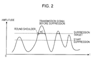
- a technique related to hard clipping a technique for suppressing a steep variation in a signal by applying a predetermined function to round the shoulder of the waveform after peak suppression (see FIG. 2 ) is known in order to suppress a steep variation in signal at a point at which suppression through hard clipping is started (see Japanese Laid-open Patent Publication No. 10-178414 ).
- the transmitter allocates a frequency for transmitting peak suppression information.
- frequencies that are allocatable to a user are reduced and, therefore, frequency use efficiency decreases.
- a peak suppressing and restoring method includes suppressing a peak of a signal by starting suppression when a suppression start value is lower than a suppression target value and using a function of a gain characteristic such that a peak amplitude value attains the suppression target value, and restoring the suppressed peak of the signal using an inverse function of the function of the gain characteristic.
- FIG. 1 is a block diagram illustrating a prior art
- FIG. 2 is a graph illustrating the prior art
- FIG. 3 is a block diagram that illustrates the configuration of a transmitter according to a first embodiment
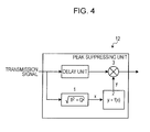
- FIG. 4 is a view illustrating a peak suppressing unit of the transmitter
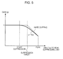
- FIG. 5 is a graph illustrating the process of the peak suppressing unit
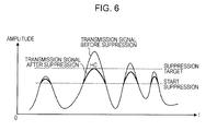
- FIG. 6 is a graph that illustrates the state of waveform before and after peak suppression
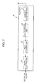
- FIG. 7 is a block diagram that illustrates the configuration of a receiver according to the first embodiment
- FIG. 8 is a view illustrating a peak restoring unit of the receiver
- FIG. 9 is a graph illustrating the process of the peak restoring unit
- FIG. 10 is a graph that illustrates a comparison between the waveforms of input/output signals of the peak restoring unit
- FIG. 11 is a flowchart that illustrates the operation of the transmitter according to the first embodiment
- FIG. 12 is a flowchart that illustrates the operation of the receiver according to the first embodiment
- FIG. 13 is a view illustrating a receiver according to a second embodiment
- FIG. 14 is a view illustrating a difference in PAPR in a reception signal suppressed by different peak suppression amounts.
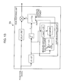
- FIG. 15 is a view illustrating a transmitter according to a third embodiment.
- the transmitter 10 includes a digital modulation unit 11, a peak suppressing unit 12, a D/A conversion unit 13, and a wireless transmission unit 14, and transmits a signal to a receiver 20 through an antenna.
- a digital modulation unit 11 a peak suppressing unit 12
- a D/A conversion unit 13 a D/A conversion unit 13
- a wireless transmission unit 14 transmits a signal to a receiver 20 through an antenna.
- the digital modulation unit 11 digitally modulates input transmission data, and outputs the digitally modulated transmission data to the peak suppressing unit 12 as a transmission signal.
- the peak suppressing unit 12 starts suppression when a suppression start value is smaller than a suppression target value, suppresses a peak of the signal using a function f(x) having gain characteristics such that only a peak amplitude value attains the suppression target value, and then outputs the resultant signal to the D/A conversion unit 13.
- the peak suppressing unit 12 accepts the transmission signal output from the digital modulation unit 11, obtains an amplitude value (x) of the transmission signal, which is a complex number (see operation 1 in FIG. 4 ), and calculates a peak suppression signal (y) using the function f(x) (see operation 2 in FIG. 4 ). Then, the peak suppressing unit 12 multiplies the transmission signal, delayed by a delay unit, by the peak suppression signal (gain) to suppress a peak (see operation 3 in FIG. 4 ).
- a gain is determined so that a peak signal that exceeds a suppression target value is clipped to the target value.
- the peak suppression process executed by the peak suppressing unit 12 using the function f(x) differs from the hard clipping in that peak suppression is carried out when an amplitude value is lower than a suppression target value (in the example illustrated in FIG. 5 , from the level of "start suppression").
- the peak suppressing unit 12 determines a gain substantially equal to that of the hard clipping at the maximum peak of the signal, but the peak suppressing unit 12 determines a gain that performs peak suppression on peaks other than the maximum peak more severely than hard clipping.
- FIG. 6 illustrates a difference in waveform when peak suppression is performed using the function f(x) and when peak suppression is performed by hard clipping.
- the waveform after peak suppression is performed using the function f(x) as a waveform such that the part of the signal that exceeds a suppression start value is suppressed and the maximum peak is suppressed to a suppression target.
- the D/A conversion unit 13 digital-to-analog converts the transmission signal output from the peak suppressing unit 12, and outputs the converted transmission signal to the wireless transmission unit 14.
- the wireless transmission unit 14 converts the frequency of the transmission signal output from the D/A conversion unit 13, and transmits a wireless signal.
- the receiver 20 includes a wireless reception unit 21, an A/D conversion unit 22, a peak restoring unit 23, and a digital decoding unit 24, and receives a signal from the transmitter 20 through an antenna.
- a wireless reception unit 21 an A/D conversion unit 22, a peak restoring unit 23, and a digital decoding unit 24, and receives a signal from the transmitter 20 through an antenna.
- the wireless reception unit 21 converts the frequency of the received signal, and outputs the converted signal to the A/D conversion unit 22 as a reception signal.
- the A/D conversion unit 22 performs analog-to-digital conversion of the reception signal, and outputs the converted reception signal to the peak restoring unit 23.
- the peak restoring unit 23 restores the suppressed peak of the reception signal using an inverse function f-1(x), and outputs the peak-restored reception signal to the digital decoding unit 24. As illustrated in FIG. 8 , the peak restoring unit 23 accepts the reception signal output from the A/D conversion unit 22, and obtains an amplitude value (x) of the reception signal, which is a complex number (see operation 1 in FIG. 8 ).
- the peak restoring unit 23 obtains a peak restored signal (y) using the function f-1(x) having an inverted characteristic to the function used by the peak suppressing unit 12 of the above described transmitter 10 (see operation 2 in FIG. 8 ).
- the peak restoring unit 23 multiplies the reception signal, which is delayed by a delay unit, by the peak restored signal (gain) to restore a peak (see operation 3 in FIG. 8 ).
- the process of the peak restoring unit will be described with reference to FIG. 9 and FIG. 10 .
- the peak restoring unit 23 restores a signal component over which peak suppression has been executed by the peak suppressing unit 12 of the transmitter 10.
- an input signal waveform of the peak restoring unit is compared with an output signal waveform of the peak restoring unit to restore a peak having an amplitude value higher than the level of "start suppression".
- the digital decoding unit 24 digitally decodes the reception signal output from the peak restoring unit 23, and outputs the decoded reception data to the outside.
- the transmitter 10 digitally modulates an input transmission signal (step S101). Then, the transmitter 10 starts suppression over the transmission signal when a suppression start value is lower than a suppression target value, and suppresses a peak of the signal using the function f(x) having gain characteristics such that only a peak amplitude value attains the suppression target value (step S102).
- the transmitter 10 performs digital-to-analog conversion of the transmission signal, the peak of which is suppressed (step S103). After that, the transmitter 10 converts the frequency of the digital-to-analog converted transmission signal to transmit a wireless signal (step S104).
- the receiver 20 As illustrated in FIG. 12 , as the receiver 20 receives a signal from the transmitter (Yes in step S201), the receiver 20 converts the frequency of the received signal, and performs analog-to-digital conversion of the reception signal the frequency of which is converted (step S202). Then, the receiver 20 restores the suppressed peak of the reception signal using the inverse function f-1(x) (step S203). After that, the receiver 20 digitally decodes the restored reception signal (step S204).
- suppression is started when a suppression start value is lower than a suppression target value, and suppresses a peak using the function having gain characteristics such that only a peak amplitude value attains the suppression target value, thus restoring the suppressed peak using the inverse function.
- peak suppression is executed such that information related to peak suppression executed by the transmitter 10 is not transmitted and the waveform of the peak is maintained. As a result, it is possible to restore a peak at the reception side while improving signal quality at the reception side. Thus, it is possible to improve frequency use efficiency.
- the transmitter 10 calculates a peak suppression signal (gain), which is a degree of peak suppression, using the function, and suppresses a peak based on the peak suppression signal.
- the receiver 20 calculates a degree of peak restoration using the inverse function, and restores a peak based on the degree of peak restoration.
- a receiver determines the amount of peak suppression, and adjusts the amount of peak restoration based on the determined amount of peak suppression.
- Other configurations are similar to those of the first embodiment.
- a peak restoring unit 23a of the receiver 20a differs from the peak restoring unit 23 of the receiver 20 illustrated in FIG. 8 in that a peak-to-average power ratio (PAPR) measuring circuit is additionally provided.
- PAPR peak-to-average power ratio
- the peak restoring unit 23a of the receiver 20a obtains amplitude values (x) of a reception signal, which is a complex number, as in the case of the first embodiment, and measures an average electric power and a PAPR, which is different from the first embodiment.
- the peak restoring unit 23a compares a peak (max (I2 + Q2)) with an average electric power as a process of measuring the PAPR, and measures a ratio of the average electric power to the peak as the PAPR. Subsequently, the peak restoring unit 23a determines the amount of peak suppression (suppression target value and suppression start value) based on the average electric power and the PAPR, and sets the determined suppression target value and suppression start value to adjust the amount of peak restoration.
- FIG. 14 illustrates a relationship between a PAPR and a CCDF (Complementary Cumulative Distribution Function).
- CCDF Complementary Cumulative Distribution Function
- the receiver 20a determines the amount of peak suppression and adjusts the amount of peak restoration.
- the receiver 20a measures a ratio of an average electric power to a peak to determine the amount of peak suppression, and then adjusts the amount of peak restoration based on the amount of peak suppression.
- the amount of peak suppression (suppression target value and suppression start value) set in the transmitter is not set in the receiver 20a, it is possible to appropriately restore a peak.
- the peak suppressing unit 12 obtains an amplitude value (x), calculates a peak suppression signal (y) using the function f(x) and then multiplies a transmission signal by the peak suppression signal (gain) to suppress a peak.
- the peak suppressing unit 12 includes a memory that stores an amplitude value (x) and a peak suppression signal (y) in correlation with each other, and data is read from the memory. Other configurations are similar to those of the first embodiment.
- the peak suppressing unit of the transmitter includes a memory that stores an amplitude value (x) and a peak suppression signal (y) in correlation with each other.
- the peak suppressing unit of the transmitter obtains an amplitude value (x) of a transmission signal, which is a complex number, reads a peak suppression signal (y) corresponding to the amplitude value (x) from the memory, and multiplies the transmission signal by the peak suppression signal to suppress a peak.
- the receiver may also execute a similar process to restore a peak.
- the transmitter reads a peak suppression signal corresponding to an amplitude value of a transmitting signal from the memory that stores an amplitude value and a peak suppression signal in correlation with each other, and then suppresses a peak of the transmitting signal based on the peak suppression signal.
- the receiver reads a peak restoration signal corresponding to an amplitude value of a received signal from the memory that stores an amplitude value and a peak restoration signal in correlation with each other, and restores a peak of the received signal based on the peak restoration signal. As a result, it is possible to easily suppress and restore a peak.
- the components of the transmitter 10 and receiver 20 illustrated in FIG. 3 and FIG. 7 are functional concepts, and are not necessarily physically configured as illustrated in the drawings.
- the entire or a selected portion of processing functions executed in the components (for example, the peak suppressing unit 12 or the peak restoring unit 23) of the transmitter 10 and receiver 20 may be implemented by a CPU, a program executed for analysis in the CPU, and the like.
- various processes described in the first embodiment may be implemented in such a manner that a prepared program is executed on a processing apparatus, such as a CPU (Central Processing Unit), provided for a communication device (computer).
- a processing apparatus such as a CPU (Central Processing Unit), provided for a communication device (computer).
- CPU Central Processing Unit
- the invention also provides a computer program or a computer program product for carrying out any of the methods described herein, and a computer readable medium having stored thereon a program for carrying out any of the methods described herein.
- a computer program embodying the invention may be stored on a computer-readable medium, or it could, for example, be in the form of a signal such as a downloadable data signal provided from an Internet website, or it could be in any other form.
Landscapes
- Engineering & Computer Science (AREA)
- Computer Networks & Wireless Communication (AREA)
- Signal Processing (AREA)
- Transmitters (AREA)
- Circuits Of Receivers In General (AREA)
Abstract
Description
- Embodiments of the present invention relate to a peak suppressing and restoring method, transmitter, receiver, and peak suppressing and restoring system that suppress and restore a peak of a signal in communication.
- In communication, such as wireless communication, a technique for suppressing a peak of a transmission signal has been used for improving the electric power use efficiency of an amplifier. That is, the electric power use efficiency of the amplifier improves as the amplifier is operated close to saturation electric power. Thus, by suppressing a peak component of a signal through peak suppression in advance, the amplifier operates as close as possible to saturation electric power.
- For example, a technique illustrated in
FIG. 1 is known as a method of suppressing a peak and a method of restoring a suppressed peak. In this technique, a transmitter suppresses a peak, and then transmits peak suppression information related to peak suppression integrated with transmission data.
Then, a receiver receives the peak suppression information, and then uses the received peak suppression information to restore the peak-suppressed signal (see Japanese Laid-open Patent Publication No.2001-274768 - In addition, a peak suppressing method using hard clipping is known as a technique for suppressing a peak. Specifically, the peak suppressing method is a method in which a gain is determined so that a peak of a signal that exceeds a suppression target value is clipped to the target value. Note that as a technique related to hard clipping, a technique for suppressing a steep variation in a signal by applying a predetermined function to round the shoulder of the waveform after peak suppression (see
FIG. 2 ) is known in order to suppress a steep variation in signal at a point at which suppression through hard clipping is started (see Japanese Laid-open Patent Publication No.10-178414 - Here, in the technique for transmitting peak suppression information, the transmitter allocates a frequency for transmitting peak suppression information. As a result, there is a problem that frequencies that are allocatable to a user are reduced and, therefore, frequency use efficiency decreases.
- Accordingly, it is desirable to provide a peak suppressing and restoring method, transmitter, receiver, and peak suppressing and restoring system which may improve frequency use efficiency without transmitting peak suppression information.
- According to one aspect of the embodiments discussed herein, a peak suppressing and restoring method is provided. The peak suppressing and restoring method includes suppressing a peak of a signal by starting suppression when a suppression start value is lower than a suppression target value and using a function of a gain characteristic such that a peak amplitude value attains the suppression target value, and restoring the suppressed peak of the signal using an inverse function of the function of the gain characteristic.
- Additional desirable features and advantages of the embodiments will be set forth in part in the description which follows, and in part may become apparent from the description, or may be learned by practice of the embodiments. The desirable features and advantages of the embodiments will be realized and attained by means of the elements and combinations particularly pointed out in the appended claims.
- It is to be understood that both the foregoing summary description and the following detailed description are exemplary and explanatory and are not restrictive of the embodiments, as claimed.
- Preferred features of the present invention will now be described, purely by way of example, with reference to the accompanying drawings, in which:-
-
FIG. 1 is a block diagram illustrating a prior art; -
FIG. 2 is a graph illustrating the prior art; -
FIG. 3 is a block diagram that illustrates the configuration of a transmitter according to a first embodiment; -
FIG. 4 is a view illustrating a peak suppressing unit of the transmitter; -
FIG. 5 is a graph illustrating the process of the peak suppressing unit; -
FIG. 6 is a graph that illustrates the state of waveform before and after peak suppression; -
FIG. 7 is a block diagram that illustrates the configuration of a receiver according to the first embodiment; -
FIG. 8 is a view illustrating a peak restoring unit of the receiver; -
FIG. 9 is a graph illustrating the process of the peak restoring unit; -
FIG. 10 is a graph that illustrates a comparison between the waveforms of input/output signals of the peak restoring unit; -
FIG. 11 is a flowchart that illustrates the operation of the transmitter according to the first embodiment; -
FIG. 12 is a flowchart that illustrates the operation of the receiver according to the first embodiment; -
FIG. 13 is a view illustrating a receiver according to a second embodiment; -
FIG. 14 is a view illustrating a difference in PAPR in a reception signal suppressed by different peak suppression amounts; and -
FIG. 15 is a view illustrating a transmitter according to a third embodiment. - Hereinafter, the configuration and process flow of each of a transmitter and a receiver according to a first embodiment will be described sequentially, and lastly advantageous effects according to the first embodiment will be described.
- First, the configuration of a
transmitter 10 according to the first embodiment illustrated inFIG. 3 will be described with reference toFIG. 3 to FIG. 6 . - As illustrated in
FIG. 3 , thetransmitter 10 includes adigital modulation unit 11, apeak suppressing unit 12, a D/A conversion unit 13, and awireless transmission unit 14, and transmits a signal to areceiver 20 through an antenna. Hereinafter, the processes of these units will be described. - The
digital modulation unit 11 digitally modulates input transmission data, and outputs the digitally modulated transmission data to thepeak suppressing unit 12 as a transmission signal. Thepeak suppressing unit 12 starts suppression when a suppression start value is smaller than a suppression target value, suppresses a peak of the signal using a function f(x) having gain characteristics such that only a peak amplitude value attains the suppression target value, and then outputs the resultant signal to the D/A conversion unit 13. - As illustrated in
FIG. 4 , thepeak suppressing unit 12 accepts the transmission signal output from thedigital modulation unit 11, obtains an amplitude value (x) of the transmission signal, which is a complex number (seeoperation 1 inFIG. 4 ), and calculates a peak suppression signal (y) using the function f(x) (seeoperation 2 inFIG. 4 ). Then, thepeak suppressing unit 12 multiplies the transmission signal, delayed by a delay unit, by the peak suppression signal (gain) to suppress a peak (seeoperation 3 inFIG. 4 ). - Here, the process using the function f(x) in the peak suppressing unit will be described in detail using the example illustrated in
FIG. 5 . In the example illustrated inFIG. 5 , for comparison, an example in which peak suppression is carried out by existing hard clipping is illustrated together with an example in which a peak of the signal is suppressed using the function f(x). - As illustrated in
FIG. 5 , in the hard clipping, a gain is determined so that a peak signal that exceeds a suppression target value is clipped to the target value. In contrast, the peak suppression process executed by thepeak suppressing unit 12 using the function f(x) differs from the hard clipping in that peak suppression is carried out when an amplitude value is lower than a suppression target value (in the example illustrated inFIG. 5 , from the level of "start suppression"). In addition, thepeak suppressing unit 12 determines a gain substantially equal to that of the hard clipping at the maximum peak of the signal, but thepeak suppressing unit 12 determines a gain that performs peak suppression on peaks other than the maximum peak more severely than hard clipping. - In addition,
FIG. 6 illustrates a difference in waveform when peak suppression is performed using the function f(x) and when peak suppression is performed by hard clipping. As illustrated inFIG. 6 , the waveform after peak suppression is performed using the function f(x) as a waveform such that the part of the signal that exceeds a suppression start value is suppressed and the maximum peak is suppressed to a suppression target. - The D/
A conversion unit 13 digital-to-analog converts the transmission signal output from thepeak suppressing unit 12, and outputs the converted transmission signal to thewireless transmission unit 14. Thewireless transmission unit 14 converts the frequency of the transmission signal output from the D/A conversion unit 13, and transmits a wireless signal. - Next, the configuration of the
receiver 20 illustrated inFIG. 7 will be described with reference toFIG. 7 to FIG. 10 . - As illustrated in
FIG. 7 , thereceiver 20 includes awireless reception unit 21, an A/D conversion unit 22, apeak restoring unit 23, and adigital decoding unit 24, and receives a signal from thetransmitter 20 through an antenna. Hereinafter, the processes of these units will be described. - The
wireless reception unit 21 converts the frequency of the received signal, and outputs the converted signal to the A/D conversion unit 22 as a reception signal. The A/D conversion unit 22 performs analog-to-digital conversion of the reception signal, and outputs the converted reception signal to thepeak restoring unit 23. - The
peak restoring unit 23 restores the suppressed peak of the reception signal using an inverse function f-1(x), and outputs the peak-restored reception signal to thedigital decoding unit 24. As illustrated inFIG. 8 , thepeak restoring unit 23 accepts the reception signal output from the A/D conversion unit 22, and obtains an amplitude value (x) of the reception signal, which is a complex number (seeoperation 1 inFIG. 8 ). - The
peak restoring unit 23 obtains a peak restored signal (y) using the function f-1(x) having an inverted characteristic to the function used by thepeak suppressing unit 12 of the above described transmitter 10 (seeoperation 2 inFIG. 8 ). Thepeak restoring unit 23 multiplies the reception signal, which is delayed by a delay unit, by the peak restored signal (gain) to restore a peak (seeoperation 3 inFIG. 8 ). - Here, the process of the peak restoring unit will be described with reference to
FIG. 9 andFIG. 10 . As illustrated inFIG. 9 , thepeak restoring unit 23 restores a signal component over which peak suppression has been executed by thepeak suppressing unit 12 of thetransmitter 10. As illustrated inFIG. 10 , in thepeak restoring unit 23, an input signal waveform of the peak restoring unit is compared with an output signal waveform of the peak restoring unit to restore a peak having an amplitude value higher than the level of "start suppression". - The
digital decoding unit 24 digitally decodes the reception signal output from thepeak restoring unit 23, and outputs the decoded reception data to the outside. - Next, the processes executed by the
transmitter 10 according to the first embodiment will be described with reference toFIG. 11 . - As illustrated in
FIG. 11 , thetransmitter 10 digitally modulates an input transmission signal (step S101). Then, thetransmitter 10 starts suppression over the transmission signal when a suppression start value is lower than a suppression target value, and suppresses a peak of the signal using the function f(x) having gain characteristics such that only a peak amplitude value attains the suppression target value (step S102). - Subsequently, the
transmitter 10 performs digital-to-analog conversion of the transmission signal, the peak of which is suppressed (step S103). After that, thetransmitter 10 converts the frequency of the digital-to-analog converted transmission signal to transmit a wireless signal (step S104). - Next, the processes executed by the
receiver 20 according to the first embodiment will be described with reference toFIG. 12 . - As illustrated in
FIG. 12 , as thereceiver 20 receives a signal from the transmitter (Yes in step S201), thereceiver 20 converts the frequency of the received signal, and performs analog-to-digital conversion of the reception signal the frequency of which is converted (step S202). Then, thereceiver 20 restores the suppressed peak of the reception signal using the inverse function f-1(x) (step S203). After that, thereceiver 20 digitally decodes the restored reception signal (step S204). - As described above, in the first embodiment, suppression is started when a suppression start value is lower than a suppression target value, and suppresses a peak using the function having gain characteristics such that only a peak amplitude value attains the suppression target value, thus restoring the suppressed peak using the inverse function. Thus, peak suppression is executed such that information related to peak suppression executed by the
transmitter 10 is not transmitted and the waveform of the peak is maintained. As a result, it is possible to restore a peak at the reception side while improving signal quality at the reception side. Thus, it is possible to improve frequency use efficiency. - In addition, according to the first embodiment, the
transmitter 10 calculates a peak suppression signal (gain), which is a degree of peak suppression, using the function, and suppresses a peak based on the peak suppression signal. In addition, thereceiver 20 calculates a degree of peak restoration using the inverse function, and restores a peak based on the degree of peak restoration. As a result, it is not necessary to transmit or receive information related to peak suppression, and it is also possible to improve frequency use efficiency while improving signal quality at the reception side. - Next, a second embodiment will be described with reference to
FIG. 13 andFIG. 14 . In the second embodiment, a receiver determines the amount of peak suppression, and adjusts the amount of peak restoration based on the determined amount of peak suppression. Other configurations are similar to those of the first embodiment. - First, the configuration and processes of a receiver 20a according to the second embodiment will be described. As illustrated in
FIG. 13 , apeak restoring unit 23a of the receiver 20a differs from thepeak restoring unit 23 of thereceiver 20 illustrated inFIG. 8 in that a peak-to-average power ratio (PAPR) measuring circuit is additionally provided. - With the above configuration, the
peak restoring unit 23a of the receiver 20a obtains amplitude values (x) of a reception signal, which is a complex number, as in the case of the first embodiment, and measures an average electric power and a PAPR, which is different from the first embodiment. - Specifically, the
peak restoring unit 23a compares a peak (max (I2 + Q2)) with an average electric power as a process of measuring the PAPR, and measures a ratio of the average electric power to the peak as the PAPR. Subsequently, thepeak restoring unit 23a determines the amount of peak suppression (suppression target value and suppression start value) based on the average electric power and the PAPR, and sets the determined suppression target value and suppression start value to adjust the amount of peak restoration. - Here,
FIG. 14 illustrates a relationship between a PAPR and a CCDF (Complementary Cumulative Distribution Function). As illustrated inFIG. 14 , when the amount of peak suppression set by the transmitter varies, the value of PAPR also varies. For example, as the amount of peak suppression increases (as the suppression target value decreases or as the suppression start value decreases), the PAPR decreases. On the other hand, when no peak suppression is executed, the PAPR reaches a maximum value. - That is, when the amount of peak suppression (suppression target value and suppression start value) set in the transmitter is not set in the receiver 20a, the receiver 20a determines the amount of peak suppression and adjusts the amount of peak restoration.
- In this way, in the second embodiment, the receiver 20a measures a ratio of an average electric power to a peak to determine the amount of peak suppression, and then adjusts the amount of peak restoration based on the amount of peak suppression. Thus, even when the amount of peak suppression (suppression target value and suppression start value) set in the transmitter is not set in the receiver 20a, it is possible to appropriately restore a peak.
- Next, a third embodiment will be described with reference to
FIG. 15 . In the first embodiment, thepeak suppressing unit 12 obtains an amplitude value (x), calculates a peak suppression signal (y) using the function f(x) and then multiplies a transmission signal by the peak suppression signal (gain) to suppress a peak. In the third embodiment, thepeak suppressing unit 12 includes a memory that stores an amplitude value (x) and a peak suppression signal (y) in correlation with each other, and data is read from the memory. Other configurations are similar to those of the first embodiment. - As illustrated in
FIG. 15 , the peak suppressing unit of the transmitter includes a memory that stores an amplitude value (x) and a peak suppression signal (y) in correlation with each other. The peak suppressing unit of the transmitter obtains an amplitude value (x) of a transmission signal, which is a complex number, reads a peak suppression signal (y) corresponding to the amplitude value (x) from the memory, and multiplies the transmission signal by the peak suppression signal to suppress a peak. The receiver may also execute a similar process to restore a peak. - In this way, the transmitter reads a peak suppression signal corresponding to an amplitude value of a transmitting signal from the memory that stores an amplitude value and a peak suppression signal in correlation with each other, and then suppresses a peak of the transmitting signal based on the peak suppression signal. In addition, the receiver reads a peak restoration signal corresponding to an amplitude value of a received signal from the memory that stores an amplitude value and a peak restoration signal in correlation with each other, and restores a peak of the received signal based on the peak restoration signal. As a result, it is possible to easily suppress and restore a peak.
- As described above, according to the first to third embodiments, it is possible to improve frequency use efficiency without transmitting peak suppression information. Note that in the first to third embodiments, as a system configuration, for example, the components of the
transmitter 10 andreceiver 20 illustrated inFIG. 3 andFIG. 7 are functional concepts, and are not necessarily physically configured as illustrated in the drawings. In addition, for example, the entire or a selected portion of processing functions executed in the components (for example, thepeak suppressing unit 12 or the peak restoring unit 23) of thetransmitter 10 andreceiver 20 may be implemented by a CPU, a program executed for analysis in the CPU, and the like. - For example, various processes described in the first embodiment (see
FIG. 11 ,FIG. 12 , and the like) may be implemented in such a manner that a prepared program is executed on a processing apparatus, such as a CPU (Central Processing Unit), provided for a communication device (computer). - All examples and conditional language recited herein are intended for pedagogical purposes to aid the reader in understanding the invention and the concepts contributed by the inventor to furthering the art, and are to be construed as being without limitation to such specifically recited examples and conditions, nor does the organization of such examples in the specification relate to a showing of the superiority and inferiority of embodiments of the invention. Although the embodiments have been described in detail, it should be understood that the various changes, substitutions, and alterations could be made hereto without departing from the scope of the invention.
- In any of the above aspects, the various features may be implemented in hardware, or as software modules running on one or more processors. Features of one aspect may be applied to any of the other aspects.
- The invention also provides a computer program or a computer program product for carrying out any of the methods described herein, and a computer readable medium having stored thereon a program for carrying out any of the methods described herein. A computer program embodying the invention may be stored on a computer-readable medium, or it could, for example, be in the form of a signal such as a downloadable data signal provided from an Internet website, or it could be in any other form.
Claims (10)
- A peak suppressing and restoring method comprising:suppressing a peak of a signal by starting suppression when a suppression start value is lower than a suppression target value and using a function of a gain characteristic such that a peak amplitude value attains the suppression target value; andrestoring the suppressed peak of the signal using an inverse function of the function of the gain characteristic.
- The peak suppressing and restoring method according to Claim 1, further comprising:determining a degree of peak suppression by measuring a ratio of an average electric power to a peak, and suppressing the peak of the signal based on the degree of peak suppression, andadjusting a degree of peak restoration based on the degree of peak suppression, and restoring the peak of the signal based on the degree of peak restoration.
- The peak suppressing and restoring method according to Claim 1 or 2, further comprising:calculating a degree of peak suppression using the function of the gain characteristic, and suppressing the peak of the signal based on the degree of peak suppression, andcalculating a degree of peak restoration using the inverse function, and restoring the peak of the signal based on the degree of peak restoration.
- The peak suppressing and restoring method according to any of Claims 1 to 3, further comprising:reading a degree of peak suppression corresponding to an amplitude value of a transmitting signal from a peak suppression storage unit that stores an amplitude value and a degree of peak suppression in correlation with each other, and suppressing the peak of the transmitting signal based on the degree of peak suppression, andreading a degree of peak restoration corresponding to an amplitude value of a received signal from a peak restoration storage unit that stores an amplitude value and a degree of peak restoration in correlation with each other, and restoring the peak of the received signal based on the degree of peak restoration.
- A transmitter comprising:a peak suppressing unit configured to start suppressing a peak of a signal when a suppression start value is lower than a suppression target value and to suppress the peak of the signal using a function of gain characteristics such that a peak amplitude value attains the suppression target value; anda transmission unit configured to transmit the signal, the peak of which is suppressed by the peak suppressing unit.
- A receiver comprising:a reception unit configured to receive a signal, a peak of which is suppressed by a peak suppressing process, from a transmitter; anda peak restoring unit configured to restore the peak of the received signal using an inverse function of a function of a gain characteristic used in the peak suppressing process.
- A peak suppressing and restoring system comprising:a transmitter that includes a peak suppressing unit configured to start suppression when a suppression start value is lower than a suppression target value and to suppress a peak using a function of a gain characteristic such that a peak amplitude value attains the suppression target value; anda receiver that includes a peak restoring unit configured to restore the peak suppressed by the peak suppressing unit using an inverse function of the function of the gain characteristic.
- The peak suppressing and restoring system according to Claim 7, wherein
the peak suppressing unit determines a degree of peak suppression by measuring a ratio of an average electric power to the peak, and
the peak restoring unit adjusts a degree of peak restoration based on the degree of peak suppression. - The peak suppressing and restoring system according to Claim 7 or 8, wherein
the peak suppressing unit calculates the degree of peak suppression using the function of the gain characteristic, and suppresses the peak of a signal based on the degree of peak suppression, and
the peak restoring unit calculates the degree of peak restoration using the inverse function, and restores the peak of the signal based on the degree of peak restoration. - The peak suppressing and restoring system according to any of Claims 7 to 9, wherein
the peak suppressing unit reads the degree of peak suppression corresponding to an amplitude value of a transmitting signal from a peak suppression storage unit that stores an amplitude value and the degree of peak suppression in correlation with each other, and suppresses the peak of the transmitting signal based on the degree of peak suppression, and
the peak restoring unit reads the degree of peak restoration corresponding to an amplitude value of a received signal from a peak restoration storage unit that stores the amplitude value and the degree of peak restoration in correlation with each other, and restores the peak of the received signal based on the degree of peak restoration.
Applications Claiming Priority (1)
| Application Number | Priority Date | Filing Date | Title |
|---|---|---|---|
| JP2008174684A JP5262361B2 (en) | 2008-07-03 | 2008-07-03 | Peak suppression restoration method, transmitter, receiver, and peak suppression restoration system |
Publications (2)
| Publication Number | Publication Date |
|---|---|
| EP2141874A1 true EP2141874A1 (en) | 2010-01-06 |
| EP2141874B1 EP2141874B1 (en) | 2015-04-15 |
Family
ID=41226203
Family Applications (1)
| Application Number | Title | Priority Date | Filing Date |
|---|---|---|---|
| EP09161957.7A Not-in-force EP2141874B1 (en) | 2008-07-03 | 2009-06-04 | Peak suppressing and restoring method, receiver, and peak suppressing and restoring system |
Country Status (5)
| Country | Link |
|---|---|
| US (1) | US8009756B2 (en) |
| EP (1) | EP2141874B1 (en) |
| JP (1) | JP5262361B2 (en) |
| KR (1) | KR101121828B1 (en) |
| CN (1) | CN101621307B (en) |
Cited By (4)
| Publication number | Priority date | Publication date | Assignee | Title |
|---|---|---|---|---|
| EP2348685A3 (en) * | 2010-01-25 | 2012-05-23 | Samsung Electronics Co., Ltd. | Method and apparatus for reducing peak to average power ratio using peak windowing |
| WO2021178121A1 (en) * | 2020-03-04 | 2021-09-10 | Qualcomm Incorporated | Reducing peak-to-average power ratio (papr) using peak suppression information messages |
| US20210328752A1 (en) * | 2020-04-15 | 2021-10-21 | Qualcomm Incorporated | Peak suppression information multiplexing on downlink shared channel |
| WO2021211462A1 (en) * | 2020-04-15 | 2021-10-21 | Qualcomm Incorporated | Peak suppression information multiplexing on uplink shared channel |
Families Citing this family (7)
| Publication number | Priority date | Publication date | Assignee | Title |
|---|---|---|---|---|
| JP5618591B2 (en) * | 2010-03-29 | 2014-11-05 | 京セラ株式会社 | Signal processing device |
| US8798194B2 (en) | 2011-12-15 | 2014-08-05 | Intel Mobile Communications GmbH | Adaptive compensation of nonlinear frequency distortion in polar transmitters based on a least squares estimation |
| US8867660B2 (en) * | 2011-12-15 | 2014-10-21 | Intel Mobile Communications GmbH | Method and system to measure and compensate undue DCO frequency peaks at GFSK ramp down |
| US8638878B2 (en) | 2011-12-15 | 2014-01-28 | Intel Mobile Communications GmbH | Method and faculty to measure and compensate DCO frequency distortions using a DPLL |
| JP2014192648A (en) * | 2013-03-27 | 2014-10-06 | Nec Corp | Peak reducing circuit and peak reducing method |
| US9172570B1 (en) | 2014-06-13 | 2015-10-27 | Intel IP Corporation | Compensation of oscillator frequency pulling |
| US20210409162A1 (en) * | 2020-06-30 | 2021-12-30 | Qualcomm Incorporated | Peak suppression information message as retransmission |
Citations (2)
| Publication number | Priority date | Publication date | Assignee | Title |
|---|---|---|---|---|
| US5287387A (en) * | 1992-03-06 | 1994-02-15 | Motorola, Inc. | Low splatter peak-to-average signal reduction |
| JPH10178414A (en) | 1996-12-19 | 1998-06-30 | Fujitsu Ltd | Code multiplex radio equipment |
Family Cites Families (18)
| Publication number | Priority date | Publication date | Assignee | Title |
|---|---|---|---|---|
| US3403327A (en) * | 1965-09-08 | 1968-09-24 | Schlumberger Technology Corp | Methods and apparatus for processing well logging measurements using time domain computation to obtain the reciprocal function of the measurements |
| JP3421452B2 (en) * | 1994-12-07 | 2003-06-30 | 富士通株式会社 | Nonlinear distortion compensator |
| JP3130794B2 (en) | 1996-05-27 | 2001-01-31 | 日本電気株式会社 | Demodulator |
| JP3522568B2 (en) * | 1999-02-25 | 2004-04-26 | 日本電信電話株式会社 | OFDM distortion compensation circuit and peak restoration circuit |
| JP2001274768A (en) * | 2000-03-27 | 2001-10-05 | Matsushita Electric Ind Co Ltd | Communication device and communication method |
| JP3990974B2 (en) * | 2002-11-26 | 2007-10-17 | 株式会社日立コミュニケーションテクノロジー | Peak factor reduction device |
| JP4110385B2 (en) * | 2002-12-02 | 2008-07-02 | 日本電気株式会社 | Power limiter |
| JP2005006186A (en) * | 2003-06-13 | 2005-01-06 | Mitsubishi Electric Corp | Wireless transmission system and receiver |
| JP3927521B2 (en) * | 2003-06-27 | 2007-06-13 | 株式会社日立国際電気 | Transmitter |
| JP2005051457A (en) * | 2003-07-28 | 2005-02-24 | Matsushita Electric Ind Co Ltd | Peak power suppression device and peak power suppression method |
| JP4469685B2 (en) * | 2004-08-25 | 2010-05-26 | 富士通株式会社 | Output power error absorption circuit and multi-carrier transmitter having the same |
| JP2006174364A (en) * | 2004-12-20 | 2006-06-29 | Fujitsu Ltd | Multicarrier signal transmission apparatus, multicarrier signal reception apparatus, multicarrier signal transmission method, multicarrier signal reception method, and communication system |
| EP1940058B1 (en) * | 2005-09-27 | 2013-11-13 | Fujitsu Ltd. | Radio transmission device having peak suppression function |
| JP2007251341A (en) * | 2006-03-14 | 2007-09-27 | Hitachi Kokusai Electric Inc | Transmitter |
| US7783260B2 (en) * | 2006-04-27 | 2010-08-24 | Crestcom, Inc. | Method and apparatus for adaptively controlling signals |
| JP4829705B2 (en) * | 2006-07-12 | 2011-12-07 | 富士通株式会社 | Peak suppression control device |
| JP2009284044A (en) * | 2008-05-20 | 2009-12-03 | Fujitsu Ltd | Radio transmission apparatus |
| US20090323857A1 (en) * | 2008-06-30 | 2009-12-31 | Singh Chitranjan K | Configurable sub-band filtering to reduce peak-to-average power ratio of ofdm signals or the like |
-
2008
- 2008-07-03 JP JP2008174684A patent/JP5262361B2/en not_active Expired - Fee Related
-
2009
- 2009-06-04 EP EP09161957.7A patent/EP2141874B1/en not_active Not-in-force
- 2009-06-05 US US12/478,932 patent/US8009756B2/en not_active Expired - Fee Related
- 2009-06-30 KR KR1020090059038A patent/KR101121828B1/en not_active Expired - Fee Related
- 2009-07-02 CN CN200910149867.2A patent/CN101621307B/en not_active Expired - Fee Related
Patent Citations (3)
| Publication number | Priority date | Publication date | Assignee | Title |
|---|---|---|---|---|
| US5287387A (en) * | 1992-03-06 | 1994-02-15 | Motorola, Inc. | Low splatter peak-to-average signal reduction |
| JPH10178414A (en) | 1996-12-19 | 1998-06-30 | Fujitsu Ltd | Code multiplex radio equipment |
| US6009090A (en) | 1996-12-19 | 1999-12-28 | Fujitsu Limited | Code multiplexing wireless apparatus |
Non-Patent Citations (2)
| Title |
|---|
| MEIER ET AL.: "Software Amplitude Limitation in Digital Signal Processing Applications", MOTOROLA TECHNICAL DEVELOPMENTS, vol. 25, 1 July 1995 (1995-07-01), pages 23 - 27 |
| MEIER W ET AL: "SOFTWARE AMPLITUDE LIMITATION IN DIGITAL SIGNAL PROCESSING APPLICATIONS", MOTOROLA TECHNICAL DEVELOPMENTS, MOTOROLA INC. SCHAUMBURG, ILLINOIS, US, vol. 25, 1 July 1995 (1995-07-01), pages 23 - 27, XP000524322, ISSN: 0887-5286 * |
Cited By (9)
| Publication number | Priority date | Publication date | Assignee | Title |
|---|---|---|---|---|
| EP2348685A3 (en) * | 2010-01-25 | 2012-05-23 | Samsung Electronics Co., Ltd. | Method and apparatus for reducing peak to average power ratio using peak windowing |
| US8548092B2 (en) | 2010-01-25 | 2013-10-01 | Samsung Electronics Co., Ltd. | Method and apparatus for reducing peak to average power ratio using peak windowing |
| WO2021178121A1 (en) * | 2020-03-04 | 2021-09-10 | Qualcomm Incorporated | Reducing peak-to-average power ratio (papr) using peak suppression information messages |
| US11190383B2 (en) | 2020-03-04 | 2021-11-30 | Qualcomm Incorporated | Reducing peak-to-average power ratio (PAPR) using peak suppression information messages |
| US20210328752A1 (en) * | 2020-04-15 | 2021-10-21 | Qualcomm Incorporated | Peak suppression information multiplexing on downlink shared channel |
| WO2021211461A1 (en) * | 2020-04-15 | 2021-10-21 | Qualcomm Incorporated | Peak suppression information multiplexing on downlink shared channel |
| WO2021211462A1 (en) * | 2020-04-15 | 2021-10-21 | Qualcomm Incorporated | Peak suppression information multiplexing on uplink shared channel |
| US11424897B2 (en) | 2020-04-15 | 2022-08-23 | Qualcomm Incorporated | Peak suppression information multiplexing on uplink shared channel |
| US11689343B2 (en) * | 2020-04-15 | 2023-06-27 | Qualcomm Incorporated | Peak suppression information multiplexing on downlink shared channel |
Also Published As
| Publication number | Publication date |
|---|---|
| KR101121828B1 (en) | 2012-03-21 |
| CN101621307B (en) | 2014-05-07 |
| KR20100004870A (en) | 2010-01-13 |
| CN101621307A (en) | 2010-01-06 |
| JP2010016626A (en) | 2010-01-21 |
| US20100003920A1 (en) | 2010-01-07 |
| EP2141874B1 (en) | 2015-04-15 |
| US8009756B2 (en) | 2011-08-30 |
| JP5262361B2 (en) | 2013-08-14 |
Similar Documents
| Publication | Publication Date | Title |
|---|---|---|
| EP2141874B1 (en) | Peak suppressing and restoring method, receiver, and peak suppressing and restoring system | |
| US8259846B2 (en) | Apparatus and method for generating a multicarrier communication signal having a reduced crest factor | |
| CN101904147B (en) | A method and device for automatic gain control | |
| US9197175B2 (en) | Methods and systems for pre-emphasis of an envelope tracking power amplifier supply voltage | |
| KR20100002268A (en) | Companded transmit path for wireless communication | |
| JP2006174364A (en) | Multicarrier signal transmission apparatus, multicarrier signal reception apparatus, multicarrier signal transmission method, multicarrier signal reception method, and communication system | |
| WO2011104955A1 (en) | Signal processing circuit and communication device containing said circuit | |
| US8385466B2 (en) | Transmitting a signal from a power amplifier | |
| US20120328048A1 (en) | Peak suppressing apparatus, peak suppressing method and wireless communications apparatus | |
| US8587376B2 (en) | Automatic gain control | |
| EP2993666A1 (en) | Voice switching device, voice switching method, and computer program for switching between voices | |
| US7889798B2 (en) | PAR reduction for EDGE clipper | |
| EP1890388A2 (en) | Peak suppressor | |
| CN107483375B (en) | Compensation method for signal group delay, signal processing circuit and mobile terminal | |
| CN116318203B (en) | Signal amplitude pre-compensation method, device and Wi-Fi transmitter | |
| US20080240287A1 (en) | Transmitter | |
| US20220022096A1 (en) | Methods and apparatuses for signal processing at base station | |
| JP5538152B2 (en) | Receiver, channel information compression method, and computer program | |
| US8615193B2 (en) | Apparatus and method for restoring a transmission signal from a reception signal transmitted through a satellite communication device | |
| EP2139184B1 (en) | Peak suppressing apparatus, peak suppressing method, and wireless communication device | |
| KR101084550B1 (en) | Peak to Average Power Ratio Reduction Method, Peak to Average Power Ratio Reduction Device, Transmitter, and Receiver | |
| JP2008086006A (en) | Signal processing method and power amplifying device | |
| JP4813931B2 (en) | Measuring device and relay device using the same | |
| CN109525264A (en) | Adaptive Signal Compression device for AM radio | |
| CN101741792A (en) | Signal processing method, device and system |
Legal Events
| Date | Code | Title | Description |
|---|---|---|---|
| PUAI | Public reference made under article 153(3) epc to a published international application that has entered the european phase |
Free format text: ORIGINAL CODE: 0009012 |
|
| AK | Designated contracting states |
Kind code of ref document: A1 Designated state(s): AT BE BG CH CY CZ DE DK EE ES FI FR GB GR HR HU IE IS IT LI LT LU LV MC MK MT NL NO PL PT RO SE SI SK TR |
|
| 17P | Request for examination filed |
Effective date: 20100630 |
|
| GRAP | Despatch of communication of intention to grant a patent |
Free format text: ORIGINAL CODE: EPIDOSNIGR1 |
|
| INTG | Intention to grant announced |
Effective date: 20141103 |
|
| GRAS | Grant fee paid |
Free format text: ORIGINAL CODE: EPIDOSNIGR3 |
|
| GRAA | (expected) grant |
Free format text: ORIGINAL CODE: 0009210 |
|
| AK | Designated contracting states |
Kind code of ref document: B1 Designated state(s): AT BE BG CH CY CZ DE DK EE ES FI FR GB GR HR HU IE IS IT LI LT LU LV MC MK MT NL NO PL PT RO SE SI SK TR |
|
| REG | Reference to a national code |
Ref country code: GB Ref legal event code: FG4D Ref country code: CH Ref legal event code: EP |
|
| REG | Reference to a national code |
Ref country code: IE Ref legal event code: FG4D |
|
| REG | Reference to a national code |
Ref country code: AT Ref legal event code: REF Ref document number: 722507 Country of ref document: AT Kind code of ref document: T Effective date: 20150515 |
|
| REG | Reference to a national code |
Ref country code: DE Ref legal event code: R096 Ref document number: 602009030631 Country of ref document: DE Effective date: 20150528 |
|
| REG | Reference to a national code |
Ref country code: NL Ref legal event code: VDEP Effective date: 20150415 |
|
| REG | Reference to a national code |
Ref country code: AT Ref legal event code: MK05 Ref document number: 722507 Country of ref document: AT Kind code of ref document: T Effective date: 20150415 |
|
| REG | Reference to a national code |
Ref country code: LT Ref legal event code: MG4D |
|
| PG25 | Lapsed in a contracting state [announced via postgrant information from national office to epo] |
Ref country code: NL Free format text: LAPSE BECAUSE OF FAILURE TO SUBMIT A TRANSLATION OF THE DESCRIPTION OR TO PAY THE FEE WITHIN THE PRESCRIBED TIME-LIMIT Effective date: 20150415 |
|
| PG25 | Lapsed in a contracting state [announced via postgrant information from national office to epo] |
Ref country code: PT Free format text: LAPSE BECAUSE OF FAILURE TO SUBMIT A TRANSLATION OF THE DESCRIPTION OR TO PAY THE FEE WITHIN THE PRESCRIBED TIME-LIMIT Effective date: 20150817 Ref country code: HR Free format text: LAPSE BECAUSE OF FAILURE TO SUBMIT A TRANSLATION OF THE DESCRIPTION OR TO PAY THE FEE WITHIN THE PRESCRIBED TIME-LIMIT Effective date: 20150415 Ref country code: NO Free format text: LAPSE BECAUSE OF FAILURE TO SUBMIT A TRANSLATION OF THE DESCRIPTION OR TO PAY THE FEE WITHIN THE PRESCRIBED TIME-LIMIT Effective date: 20150715 Ref country code: LT Free format text: LAPSE BECAUSE OF FAILURE TO SUBMIT A TRANSLATION OF THE DESCRIPTION OR TO PAY THE FEE WITHIN THE PRESCRIBED TIME-LIMIT Effective date: 20150415 Ref country code: FI Free format text: LAPSE BECAUSE OF FAILURE TO SUBMIT A TRANSLATION OF THE DESCRIPTION OR TO PAY THE FEE WITHIN THE PRESCRIBED TIME-LIMIT Effective date: 20150415 Ref country code: ES Free format text: LAPSE BECAUSE OF FAILURE TO SUBMIT A TRANSLATION OF THE DESCRIPTION OR TO PAY THE FEE WITHIN THE PRESCRIBED TIME-LIMIT Effective date: 20150415 |
|
| PG25 | Lapsed in a contracting state [announced via postgrant information from national office to epo] |
Ref country code: GR Free format text: LAPSE BECAUSE OF FAILURE TO SUBMIT A TRANSLATION OF THE DESCRIPTION OR TO PAY THE FEE WITHIN THE PRESCRIBED TIME-LIMIT Effective date: 20150716 Ref country code: AT Free format text: LAPSE BECAUSE OF FAILURE TO SUBMIT A TRANSLATION OF THE DESCRIPTION OR TO PAY THE FEE WITHIN THE PRESCRIBED TIME-LIMIT Effective date: 20150415 Ref country code: IS Free format text: LAPSE BECAUSE OF FAILURE TO SUBMIT A TRANSLATION OF THE DESCRIPTION OR TO PAY THE FEE WITHIN THE PRESCRIBED TIME-LIMIT Effective date: 20150815 Ref country code: LV Free format text: LAPSE BECAUSE OF FAILURE TO SUBMIT A TRANSLATION OF THE DESCRIPTION OR TO PAY THE FEE WITHIN THE PRESCRIBED TIME-LIMIT Effective date: 20150415 |
|
| REG | Reference to a national code |
Ref country code: DE Ref legal event code: R097 Ref document number: 602009030631 Country of ref document: DE |
|
| PG25 | Lapsed in a contracting state [announced via postgrant information from national office to epo] |
Ref country code: EE Free format text: LAPSE BECAUSE OF FAILURE TO SUBMIT A TRANSLATION OF THE DESCRIPTION OR TO PAY THE FEE WITHIN THE PRESCRIBED TIME-LIMIT Effective date: 20150415 Ref country code: DK Free format text: LAPSE BECAUSE OF FAILURE TO SUBMIT A TRANSLATION OF THE DESCRIPTION OR TO PAY THE FEE WITHIN THE PRESCRIBED TIME-LIMIT Effective date: 20150415 Ref country code: IT Free format text: LAPSE BECAUSE OF FAILURE TO SUBMIT A TRANSLATION OF THE DESCRIPTION OR TO PAY THE FEE WITHIN THE PRESCRIBED TIME-LIMIT Effective date: 20150415 Ref country code: MC Free format text: LAPSE BECAUSE OF FAILURE TO SUBMIT A TRANSLATION OF THE DESCRIPTION OR TO PAY THE FEE WITHIN THE PRESCRIBED TIME-LIMIT Effective date: 20150415 |
|
| REG | Reference to a national code |
Ref country code: CH Ref legal event code: PL |
|
| PLBE | No opposition filed within time limit |
Free format text: ORIGINAL CODE: 0009261 |
|
| STAA | Information on the status of an ep patent application or granted ep patent |
Free format text: STATUS: NO OPPOSITION FILED WITHIN TIME LIMIT |
|
| PG25 | Lapsed in a contracting state [announced via postgrant information from national office to epo] |
Ref country code: RO Free format text: LAPSE BECAUSE OF NON-PAYMENT OF DUE FEES Effective date: 20150415 Ref country code: LU Free format text: LAPSE BECAUSE OF FAILURE TO SUBMIT A TRANSLATION OF THE DESCRIPTION OR TO PAY THE FEE WITHIN THE PRESCRIBED TIME-LIMIT Effective date: 20150604 Ref country code: SK Free format text: LAPSE BECAUSE OF FAILURE TO SUBMIT A TRANSLATION OF THE DESCRIPTION OR TO PAY THE FEE WITHIN THE PRESCRIBED TIME-LIMIT Effective date: 20150415 Ref country code: PL Free format text: LAPSE BECAUSE OF FAILURE TO SUBMIT A TRANSLATION OF THE DESCRIPTION OR TO PAY THE FEE WITHIN THE PRESCRIBED TIME-LIMIT Effective date: 20150415 Ref country code: CZ Free format text: LAPSE BECAUSE OF FAILURE TO SUBMIT A TRANSLATION OF THE DESCRIPTION OR TO PAY THE FEE WITHIN THE PRESCRIBED TIME-LIMIT Effective date: 20150415 |
|
| 26N | No opposition filed |
Effective date: 20160118 |
|
| REG | Reference to a national code |
Ref country code: IE Ref legal event code: MM4A |
|
| PG25 | Lapsed in a contracting state [announced via postgrant information from national office to epo] |
Ref country code: CH Free format text: LAPSE BECAUSE OF NON-PAYMENT OF DUE FEES Effective date: 20150630 Ref country code: LI Free format text: LAPSE BECAUSE OF NON-PAYMENT OF DUE FEES Effective date: 20150630 Ref country code: IE Free format text: LAPSE BECAUSE OF NON-PAYMENT OF DUE FEES Effective date: 20150604 |
|
| REG | Reference to a national code |
Ref country code: FR Ref legal event code: PLFP Year of fee payment: 8 |
|
| PG25 | Lapsed in a contracting state [announced via postgrant information from national office to epo] |
Ref country code: SI Free format text: LAPSE BECAUSE OF FAILURE TO SUBMIT A TRANSLATION OF THE DESCRIPTION OR TO PAY THE FEE WITHIN THE PRESCRIBED TIME-LIMIT Effective date: 20150415 |
|
| PG25 | Lapsed in a contracting state [announced via postgrant information from national office to epo] |
Ref country code: BE Free format text: LAPSE BECAUSE OF FAILURE TO SUBMIT A TRANSLATION OF THE DESCRIPTION OR TO PAY THE FEE WITHIN THE PRESCRIBED TIME-LIMIT Effective date: 20150415 |
|
| PG25 | Lapsed in a contracting state [announced via postgrant information from national office to epo] |
Ref country code: MT Free format text: LAPSE BECAUSE OF FAILURE TO SUBMIT A TRANSLATION OF THE DESCRIPTION OR TO PAY THE FEE WITHIN THE PRESCRIBED TIME-LIMIT Effective date: 20150415 |
|
| REG | Reference to a national code |
Ref country code: FR Ref legal event code: PLFP Year of fee payment: 9 |
|
| PG25 | Lapsed in a contracting state [announced via postgrant information from national office to epo] |
Ref country code: HU Free format text: LAPSE BECAUSE OF FAILURE TO SUBMIT A TRANSLATION OF THE DESCRIPTION OR TO PAY THE FEE WITHIN THE PRESCRIBED TIME-LIMIT; INVALID AB INITIO Effective date: 20090604 Ref country code: BG Free format text: LAPSE BECAUSE OF FAILURE TO SUBMIT A TRANSLATION OF THE DESCRIPTION OR TO PAY THE FEE WITHIN THE PRESCRIBED TIME-LIMIT Effective date: 20150415 |
|
| PG25 | Lapsed in a contracting state [announced via postgrant information from national office to epo] |
Ref country code: CY Free format text: LAPSE BECAUSE OF FAILURE TO SUBMIT A TRANSLATION OF THE DESCRIPTION OR TO PAY THE FEE WITHIN THE PRESCRIBED TIME-LIMIT Effective date: 20150415 Ref country code: SE Free format text: LAPSE BECAUSE OF FAILURE TO SUBMIT A TRANSLATION OF THE DESCRIPTION OR TO PAY THE FEE WITHIN THE PRESCRIBED TIME-LIMIT Effective date: 20150415 |
|
| PGFP | Annual fee paid to national office [announced via postgrant information from national office to epo] |
Ref country code: DE Payment date: 20170530 Year of fee payment: 9 Ref country code: GB Payment date: 20170531 Year of fee payment: 9 Ref country code: FR Payment date: 20170511 Year of fee payment: 9 |
|
| PG25 | Lapsed in a contracting state [announced via postgrant information from national office to epo] |
Ref country code: TR Free format text: LAPSE BECAUSE OF FAILURE TO SUBMIT A TRANSLATION OF THE DESCRIPTION OR TO PAY THE FEE WITHIN THE PRESCRIBED TIME-LIMIT Effective date: 20150415 |
|
| PG25 | Lapsed in a contracting state [announced via postgrant information from national office to epo] |
Ref country code: MK Free format text: LAPSE BECAUSE OF FAILURE TO SUBMIT A TRANSLATION OF THE DESCRIPTION OR TO PAY THE FEE WITHIN THE PRESCRIBED TIME-LIMIT Effective date: 20150415 |
|
| REG | Reference to a national code |
Ref country code: DE Ref legal event code: R119 Ref document number: 602009030631 Country of ref document: DE |
|
| GBPC | Gb: european patent ceased through non-payment of renewal fee |
Effective date: 20180604 |
|
| PG25 | Lapsed in a contracting state [announced via postgrant information from national office to epo] |
Ref country code: FR Free format text: LAPSE BECAUSE OF NON-PAYMENT OF DUE FEES Effective date: 20180630 Ref country code: GB Free format text: LAPSE BECAUSE OF NON-PAYMENT OF DUE FEES Effective date: 20180604 Ref country code: DE Free format text: LAPSE BECAUSE OF NON-PAYMENT OF DUE FEES Effective date: 20190101 |