EP2141828A1 - Equalizer control apparatus, equalizer control method, and wireless terminal having that control apparatus - Google Patents
Equalizer control apparatus, equalizer control method, and wireless terminal having that control apparatus Download PDFInfo
- Publication number
- EP2141828A1 EP2141828A1 EP07740631A EP07740631A EP2141828A1 EP 2141828 A1 EP2141828 A1 EP 2141828A1 EP 07740631 A EP07740631 A EP 07740631A EP 07740631 A EP07740631 A EP 07740631A EP 2141828 A1 EP2141828 A1 EP 2141828A1
- Authority
- EP
- European Patent Office
- Prior art keywords
- wireless base
- channel estimation
- base station
- correlation value
- estimation values
- Prior art date
- Legal status (The legal status is an assumption and is not a legal conclusion. Google has not performed a legal analysis and makes no representation as to the accuracy of the status listed.)
- Withdrawn
Links
Images




Classifications
-
- H—ELECTRICITY
- H04—ELECTRIC COMMUNICATION TECHNIQUE
- H04B—TRANSMISSION
- H04B1/00—Details of transmission systems, not covered by a single one of groups H04B3/00 - H04B13/00; Details of transmission systems not characterised by the medium used for transmission
- H04B1/69—Spread spectrum techniques
- H04B1/707—Spread spectrum techniques using direct sequence modulation
-
- H—ELECTRICITY
- H04—ELECTRIC COMMUNICATION TECHNIQUE
- H04L—TRANSMISSION OF DIGITAL INFORMATION, e.g. TELEGRAPHIC COMMUNICATION
- H04L25/00—Baseband systems
- H04L25/02—Details ; arrangements for supplying electrical power along data transmission lines
- H04L25/0202—Channel estimation
-
- H—ELECTRICITY
- H04—ELECTRIC COMMUNICATION TECHNIQUE
- H04L—TRANSMISSION OF DIGITAL INFORMATION, e.g. TELEGRAPHIC COMMUNICATION
- H04L25/00—Baseband systems
- H04L25/02—Details ; arrangements for supplying electrical power along data transmission lines
- H04L25/0202—Channel estimation
- H04L25/0204—Channel estimation of multiple channels
-
- H—ELECTRICITY
- H04—ELECTRIC COMMUNICATION TECHNIQUE
- H04L—TRANSMISSION OF DIGITAL INFORMATION, e.g. TELEGRAPHIC COMMUNICATION
- H04L25/00—Baseband systems
- H04L25/02—Details ; arrangements for supplying electrical power along data transmission lines
- H04L25/03—Shaping networks in transmitter or receiver, e.g. adaptive shaping networks
- H04L25/03006—Arrangements for removing intersymbol interference
- H04L25/03012—Arrangements for removing intersymbol interference operating in the time domain
- H04L25/03019—Arrangements for removing intersymbol interference operating in the time domain adaptive, i.e. capable of adjustment during data reception
-
- H—ELECTRICITY
- H04—ELECTRIC COMMUNICATION TECHNIQUE
- H04L—TRANSMISSION OF DIGITAL INFORMATION, e.g. TELEGRAPHIC COMMUNICATION
- H04L25/00—Baseband systems
- H04L25/02—Details ; arrangements for supplying electrical power along data transmission lines
- H04L25/03—Shaping networks in transmitter or receiver, e.g. adaptive shaping networks
- H04L25/03006—Arrangements for removing intersymbol interference
- H04L2025/0335—Arrangements for removing intersymbol interference characterised by the type of transmission
- H04L2025/03426—Arrangements for removing intersymbol interference characterised by the type of transmission transmission using multiple-input and multiple-output channels
Definitions
- the present invention relates to a control apparatus for and a control method of an equalizer, and a wireless terminal having such a control apparatus.
- the present invention is suitable for use in an apparatus (a wireless terminal, such as a wireless telephone, for example) including an equalizer that equalizes reception signals in a wireless environment in which radio waves may be received from multiple wireless base stations.
- Equalizers are used as a technique for reducing multipath interferences.
- Equalizers are a technique for reducing interferences by calculating an appropriate synthesis (weighting) coefficient from estimation results of a propagation path (channel), and weighting-adding reception signals using the synthesis coefficient, thereby equalizing reception signals.
- a signal y(t) after an equalizer at time t can be expressed using a reception signal x(t) and a synthesis coefficient (tap coefficient) w(i) according to the following Eq. (1.1):
- synthesis coefficient w(t) determines characteristics of the equalizer and the processing amount.
- Conventional equalizers either calculate the synthesis coefficient w based on the correlation matrix R 0 only of the serving cell as expressed by the following Eq. (1.2) (see Non-Patent References 1 and 2 that will be listed later, for example), or calculate the tap coefficient by determining a synthesis correlation matrix by a sum of the correlation matrix R 0 of the serving cell and correlation matrixes R i of non-serving cells (base station number #i) as expressed by the following Eq. (1.3) (see Non-Patent Reference 3 that will be listed later, for example).
- a correlation matrix R can be calculated by the following Eq. (1.4) using the channel estimation value a(r, k) of the reception antenna number #r and the path number #k:
- correlation matrix R 0 of the serving cell refers to a matrix having, as an element, a correlation value based on a channel estimation value of an incoming signal (path) from a base station (serving cell) with which a wireless communication apparatus having an equalizer is communicating.
- correlation matrix of a non-serving cell R i refers to a matrix having, as an element, a correlation value based on a channel estimation value of an incoming signal (path) from a base station (interference station) other than that serving cell (the definitions of the terms will be used throughout the specification).
- Patent Reference 2 is directed to provide a noise power estimation apparatus that can estimate a chip noise power used for a weight calculation for an MMSE equalizer or the like.
- the apparatus is adapted to determine the noise power by eliminating multipath interference components from the reception power of the pilot signal for each path using the power ratio of pilot signal to data signal for each path, determining a modified reception power of the pilot signal for each path, estimating the total power of the pilot signal and the data signal included in the reception signal based on the modified reception power for the multiple paths and the predetermined power ratio, and subtracting the estimated total power from the total power of the reception signal.
- the processing amount is increased although the receiver performance is improved. That is, the calculation amount of twofold or higher is required compared to the case based solely on the correlation matrix R 0 of the serving cell since a correlation matrixes R should be calculated for the serving cell and each of the non-serving cells.
- Patent Reference 1 inadvertently may eliminate multipath signal components at timings other than the specified timing since such components are mistaken as signals from non-serving cell and multipath signal components of the serving cell are accidentally eliminated, or conversely, multipath signal components of non-serving cells may be erroneously included into multipath signal components of the serving cell, which may deteriorate the receiver performance.
- the technique in Patent Reference 2 is a technique in which the noise power from the serving cell is measured highly accurately without taking multipath signal components from non-serving cells into consideration, the receiver performance may be degraded due to interferences from non-serving cells.
- An object of the present invention is to reduce the calculation amount for determining a correlation matrix (correlation value) in a step for controlling the weighted addition in an equalizer (tap coefficient determination step).
- another object of the present invention is to improve the receiver performance by reducing the effect of interferences by a signal from non-serving cell. Note that it is an object of the present invention to provide advantages and effects that can be obtained by the best modes to implement the invention described below but cannot be obtained with conventional techniques.
- the present invention is directed to use a control apparatus for and a control method of an equalizer, and a wireless terminal having such a control apparatus as described below:
- the present invention it is possible to reduce the amount of correlation calculation required for controlling the weighted addition in an equalizer. In addition, according to the present invention, it is possible to improve the receiver performance by reducing the effect of interferences by signals from non-serving cell.
- the CPICH despreading unit (channel estimation unit) 11 is adapted to determine channel estimation values of each of common pilot signals from the serving cell (first wireless base station) and a non-serving cell (second wireless base station) by despreading signals received at one antenna #1 using a code of the serving cell (transmission station that is a serving cell) and a code of the non-serving cell (interference station, the station that sends signals that interfere with reception signals from the serving cell) .
- the CPICH despreading unit (channel estimation unit) 12 is adapted to determine channel estimation values of each of common pilot signals from the serving cell and the non-serving cell by similarly despreading signals received at the other antenna #2 using the code of the serving cell and the code of the non-serving cell.
- the FIR filtering unit 20 is adapted to equalize the above reception data (FIR filtering) for the purpose of reducing multipath interferences, and is configured to include n delay circuits 21 (n is an integer equal to or greater than 2) that delay input reception data by a unit time (one chip), and n tap multipliers 22 that multiply the outputs from the delay circuits 21 by tap coefficients w 0 , w 1 , ..., w n-1 , and an addition circuit ( ⁇ ) 23 that adds the outputs from the tap multipliers 22 (determines the total sum).
- n delay circuits 21 n is an integer equal to or greater than 2 that delay input reception data by a unit time (one chip)
- n tap multipliers 22 that multiply the outputs from the delay circuits 21 by tap coefficients w 0 , w 1 , ..., w n-1
- ⁇ addition circuit
- the window timing control unit 60 is adapted to control the number of tap coefficients w (the window timings for determining the window width) for the filtering at the FIR filtering unit 20 based on the despreading results from each of the CPICH despreading unit s 11 and 12.
- the data despreading unit 50 is adapted to despread the output of the FIR filtering unit 20 to obtain the demodulation result.
- the power estimation unit 30 is adapted to estimate the reception power based on the despreading results from each of the CPICH despreading units 11 and 12.
- the noise estimation unit 40 is adapted to determine the noise estimation value ( ⁇ 2 I). Note that the power estimation unit 30 has a function that is required for variants that will be described later, and thus may be omitted in this embodiment.
- the weight calculation unit (correlation value calculation unit, weighting control unit) 50 is adapted to determine each correlation matrix for the serving cell and the non-serving cell based on the estimation values from the estimation units 30 and 40 and the despreading results (the channel estimation values between the serving cell and the non-serving cell) from the CPICH despreading units 11 and 12, and determine the tap coefficients w for each tap multiplier 22 in the FIR filtering unit 20 from these correlation matrixes.
- the calculation amount can be reduced using a simplified matrix Q in which correlation values are calculated only for signals incoming to the antennas #1 and #2 at the same timing and remaining components are set to zero, rather than determining the correlation matrix of the non-serving cell using a calculation similar to the calculation used for determining the correlation matrix R 0 of the serving cell.
- the weight calculation unit 50 in this example is adapted to determine the correlation matrix (first correlation value) R 0 for the serving cell and the correlation matrix (second correlation value) Q for the non-serving cell according to the calculations expressed by the following Eqs. (2.2) and (2.3), and determine the tap coefficient w from these synthesis matrixes R using the following Eq. (2.1).
- the matrixes R 0 , Q, and R are all matrix having i rows and j columns, and that the channel estimation value of the antenna number #r (r1, r2) and the path number #m is expressed as Y(r, m).
- BTS wireless base station
- the correlation matrix R 0 for the BTS #1 (serving cell) is illustrated in FIG. 5
- the correlation matrix Q for the BTS #2 (non-serving cell) is illustrated in FIG. 6 .
- the tap coefficient w is determined based on the matrix depicted in FIG. 5 in Conventional Example 1 while the tap coefficient w is determined by calculating matrixes depicted in FIG. 5 for each of the BTSs #1 and #2 in Conventional Example 2 so as to improve the receiver performance.
- the receiver performance is improved while reducing the calculation amount by determining the simplified matrix Q depicted in FIG. 6 as a correlation matrix for the BTS #2.
- the wireless reception apparatus in this example is configured to include a serving cell code despreading unit 11-1 and a non-serving cell code despreading unit 11-2 as the above-described CPICH despreading unit 11, as well as including a serving cell code despreading unit 12-1 and a non-serving cell code despreading unit 12-2 as the above-described CPICH despreading unit 12, as depicted in FIG. 3 , for example.
- the weight calculation unit 50 is configured to include common pilot despreading units 51-1 to 51-4, averaging calculation units 51-1 to 51-4, timing delay circuits 52-1 and 52-2, square circuits 52-3 and 52-4, complex multipliers 53-1 and 55-1 to 55-3, adders 54-1, 54-2, 56-1 to 56-4, and 57-1 to 57-5, and a matrix calculation unit 58, as depicted in FIG. 3 , for example.
- the block illustrated in the dotted line rectangle 50-1 that is, the block having the averaging calculation units 51-1 and 51-2, the timing delay circuits 52-1 and 52-2, the complex multipliers 53-1, 55-1, and 55-2, the adders 54-1, 56-1, 56-2, and 57-1 to 57-3 functions as a serving cell correlation matrix calculation block (first wireless base station correlation value calculation unit) that determines the correlation matrix R 0 for the serving cell (BTS #1).
- a serving cell correlation matrix calculation block first wireless base station correlation value calculation unit
- the block illustrated in dotted line rectangle 50-2 that is, the block having the averaging calculation units 51-3 and 51-4, the square circuits 52-3 and 52-4, the complex multiplier 55-3, the adder 56-3, 54-2, 56-4, 57-4, and 57-5 functions as a non-serving cell correlation matrix calculation block (second wireless base station correlation value calculation unit) that determine the correlation matrix Q for the non-serving cell (BTS #2).
- a non-serving cell correlation matrix calculation block second wireless base station correlation value calculation unit
- the serving cell code despreading unit (first wireless base station channel estimation) 11-1 is adapted to determine the channel estimation value between one reception antenna #1 and the BTS #1 by despreading reception data (common pilot signal) for the reception antenna #1 using the code of the serving cell (BTS #1).
- the non-serving cell code despreading unit (second wireless base station channel estimation) 11-2 is adapted to determine the channel estimation value between the reception antenna #1 and the BTS #2 by despreading the reception data (common pilot signal) for the reception antenna #1 using the code of the non-serving cell (BTS #2).
- the serving cell code despreading unit (first wireless base station channel estimation) 12-1 is adapted to determine the channel estimation value between the other reception antenna #2 and the BTS #1 by despreading the reception data (common pilot signal) for the reception antenna #2 using the code of the serving cell.
- the non-serving cell code despreading unit (second wireless base station channel estimation) 12-2 is adapted to determine the channel estimation value between that reception antenna #2 and the BTS #2 by despreading the reception data (common pilot signal) for the reception antenna #2 using the code of the non-serving cell.
- the averaging calculation units 51-1 and 51-2 are adapted to average the despreading results (the channel estimation value with the BTS #1) from corresponding despreading units 11-1 and 12-1, respectively.
- the timing delay circuits 52-1 and 52-2 are adapted to delay the average values of the channel estimation values obtained at the averaging calculation units 51-1 and 51-2 (average channel estimation values) by (i-j) (when assuming that the correlation matrix R 0 for the serving cell is a matrix having i rows and j columns) and output delayed values to the complex multipliers 55-1 and 55-2, respectively.
- the complex multiplier 55-1 is adapted to complex-multiply the output from the timing delay circuit 52-1 by the outputs from the averaging calculation units 51-1 and 51-2.
- This complex multiplication corresponds to, when taking the reception status depicted in FIG. 4 as an example, determining the 7 x 7 block element (correlation values S, 0, ⁇ 1 * ⁇ 1 , and ⁇ 1 * ⁇ 1 ) of the upper left (the antenna #1-the antenna #1) of the matrix R 0 depicted in FIG. 5 by multiplying one of the channel estimation value ⁇ 1 and ⁇ 1 of the paths #1 and #2 that reach at one antenna #1 as a conjugate complex number with the timing deviated by (i-j) with the other of ⁇ 1 and pal.
- the complex multiplier 55-2 is adapted to complex-multiply the output from the timing delay circuit 52-2 by the outputs from the averaging calculation units 51-2 and 51-2.
- This complex multiplication corresponds to, when taking the reception status depicted in FIG. 4 as an example, determining the 7 x 7 block element (correlation values S, 0, a 2 * ⁇ 2 , and ⁇ 2 * ⁇ 2 ) of the lower right (the antenna #2-the antenna #2) of the matrix R 0 depicted in FIG. 5 by multiplying one of the channel estimation value ⁇ 2 and ⁇ 2 of the paths #1 and #2 that reach at the other antenna #2 with the timing deviated by (i-j) as a conjugate complex number with the other of ⁇ 2 and ⁇ 2 .
- the complex multiplier 53-1 is adapted to complex-multiply the outputs from the averaging calculation units 51-1 by the output from the timing delay circuit 52-2.
- This complex multiplication corresponds to, when taking the reception status depicted in FIG. 4 as an example, determining 7 x 7 block elements (correlation values C * , 0, ⁇ 2 * ⁇ 1 , ⁇ 2 * ⁇ 1 , ⁇ 1 * ⁇ 2 , and ⁇ 1 * ⁇ 2 ) of the lower left and the upper right (the antenna #1-the antenna #2 and the antenna #2-the antenna #1) of the matrix R 0 depicted in FIG.
- C * ⁇ 1 * ⁇ 2 + ⁇ 1 * ⁇ 2
- the adder 56-1 is adapted to determine the 7 x 7 block on the upper left of the matrix R 0 depicted in FIG. 5 by cumulatively adding outputs from the complex multiplier 55-1.
- the adder 56-2 is adapted to determine the 7 x 7 block on the lower right of the matrix R 0 depicted in FIG. 5 by cumulatively adding outputs from the complex multiplier 55-2.
- the adder 54-1 is adapted to determine the 7 x 7 blocks on the lower left and upper right of the matrix R 0 depicted in FIG. 5 by cumulatively adding outputs from the complex multiplier 53-1.
- the adders 57-1, 57-2, and 57-3 are adapted to determine the correlation matrix R 0 depicted in FIG. 5 for the serving cell (BTS #1) by adding (synthesizing) the addition results (block elements) from the respective adders 56-1, 54-1, and 56-2, respectively.
- the averaging calculation units 51-3 and 51-4 are adapted to average the despreading results (the channel estimation values with the BTS #2) from corresponding despreading units 11-2 and 12-2, respectively.
- the square circuits 52-3 and 52-4 are adapted to square the outputs from the corresponding averaging calculation units 51-3 and 51-4, respectively. The squares corresponds to, when taking the reception status depicted in FIG.
- the complex multiplier 55-3 is adapted to complex-multiply the output of each of the above-described averaging calculation units 51-3 and 51-4.
- the adder 56-3 is adapted to determine each of the upper left and lower right blocks of the matrix Q depicted in FIG. 6 by cumulatively adding outputs from the complex multiplier 55-3.
- the square circuits 52-3 and 52-4 are adapted to determine each of lower left and upper right blocks of the matrix Q depicted in FIG. 6 by cumulatively adding respective outputs from the adder 54-2 and 56-4, respectively.
- the adders 57-4 and 57-5 are adapted to determine the matrix Q for the non-serving cell (BTS #2) depicted in FIG. 6 expressed by Eq. (2.3) described above by adding the addition results (block elements) from the adders 56-3, 54-2, and 56-4, wherein the synthesis matrix R expressed by Eq. (2.2) described above is determined by adding (synthesizing) the matrix Q with the matrix R 0 and the noise estimation value ⁇ 2 I through the adders 57-1 to 57-3.
- the matrix calculation unit 58 is adapted to determine the tap coefficient w by resolving the above-described Eq. (2.3) based on the synthesis matrix R and the channel estimation value h obtained as outputs of the serving cell code despreading units 11-1 and 12-1 described above, and to provide the tap coefficient w to the tap multiplier 22 of the FIR filtering unit 20.
- the operation (tap coefficient calculation method) of the wireless reception apparatus that is configured as described above according to this embodiment will be described when assuming the reception environment depicted in FIG. 4 .
- Signals at the BTSs #1 and #2 arrive at the reception antennas #1 and #2, respectively, and the channel estimation values for the BTSs #1 and #2 are obtained by despreading each of the reception signals at the antennas #1 and #2 by means of the CPICH despreading unit 11 (the serving cell code despreading unit 11-1, the common pilot despreading unit 51-2), the CPICH despreading unit 12 (the serving cell code despreading unit 12-1, the common pilot despreading unit 52-2) using the spreading codes for the common pilot signals of the BTSs #1 and #2 (channel estimation step).
- the CPICH despreading unit 11 the serving cell code despreading unit 11-1, the common pilot despreading unit 51-2
- the CPICH despreading unit 12 the serving cell code despreading unit 12-1, the common pilot despreading unit 52-2
- the weight calculation unit 50 is adapted to determine the correlation matrixes R (the matrixes R 0 and Q) using the thus obtained channel estimation values to determine the tap coefficient w. More specifically, for the channel estimation values determined by the serving cell code despreading units 11-1 and 12-1 for each of the antennas #1 and #2, and at the above-described timing delay circuits 52-1 and 52-2, the complex multipliers 53-1, 55-1, and 55-2, the adders 54-1, 56-1, 56-2, and 57-1 to 57-3, the correlation matrix R 0 for the serving cell is determined by multiplying one of the channel estimation values having the timing difference (i-j) as a conjugate complex number with the other channel estimation value and executing this operation for all timings (identical and different signal timings) at which the channel estimation values are determined as described above ((serving cell) correlation value calculation step).
- R 0 ⁇ m X ⁇ r ⁇ 1 , m + i * ⁇ X ⁇ r ⁇ 2 , m + j
- channel estimation values without timing difference are multiplied at the averaging calculation units 51-3 and 51-4, the square circuits 52-3 and 52-4, the complex multiplier 55-3, the adder 54-2, 56-3, 56-4, 57-4, and 57-5 as described above (for the same antenna #1 or #2, a square sum is taken at the square circuits 52-3 and 52-4). That is, for an antenna number #r, the matrix Q for the non-serving cell is calculate according to the following Eq. (2.5) using the channel estimation value Y (r, k) for the path number #k ((non-serving cell) correlation value calculation step).
- the synthesis matrix R is determined by adding, through the adders 57-1 to 57-5, the matrix R 0 and the matrix Q calculated as described above, and the noise estimation value ⁇ 2 I determined at the noise estimation unit 40, and is entered to the matrix calculation unit 58.
- the matrix calculation unit 58 thus determines the tap coefficient w by resolving the above-described Eq. (2.1) based on the synthesis matrix R and the channel estimation value for the serving cell (the despreading results from the serving cell code despreading units 11-1 and 12-1), and provides the tap coefficient w to each of the tap multipliers 22 in the FIR filtering unit 20 (weighting control step).
- the weighted addition control (calculation of the tap coefficient w) step at the equalizer since the correlation matrix R 0 for the serving cell (correlation value) is determined based on channel estimation values for all signal timings and the correlation matrix Q for the non-serving cell (correlation value) is determined based solely on the channel estimation values at the identical signal timing, it is possible to improve the receiver performance, thereby reducing the effect of the interference wave from the non-serving cell while reducing the calculation amount.
- the correlation matrix Q for the non-serving cell is calculated based solely on the channel estimation values for the identical signal timing in the above-described embodiment. However, similar to the correlation matrix for the serving cell, the correlation matrix may be calculated based on channel estimation values at all signal timings for a non-serving cell to which signals having a power greater than a predetermined power threshold are incoming (such a non-serving cells is called as a "non-serving cell having a greater power,” and other non-serving cells are called “non-serving cells having smaller power").
- FIG. 7 the configuration corresponding to FIG. 3 is illustrated in FIG. 7 in which signals are incoming from a non-serving cell #1 having a greater power and a non-serving cell #2 having a greater smaller, other than signals from the serving cell.
- the wireless reception apparatus depicted in FIG. 7 is different from the configuration illustrated in FIG.
- a code despreading unit 11-3 that determines a channel estimation value by despreading a reception signal at the antenna #1 using the spreading code of the common pilot signal of the non-serving cell #1 and a non-serving cell code dispreading unit 12-3 that determine a channel estimation value by despreading a reception signal at the antenna #2 using the spreading code of the common pilot signal of the non-serving cell #1, and that a non-serving cell correlation matrix calculation block 50-3 that has the configuration similar to the serving cell correlation matrix calculation block 50-1 is added for the non-serving cell #1 having a greater power and a non-serving cell correlation matrix calculation block 50-2 that determines the correlation matrix Q corresponds to the non-serving cell #2 having a smaller power.
- the non-serving cell correlation matrix calculation block 50-3 is configured to include averaging calculation units 51-5 and 51-6, timing delay circuits 52-5 and 52-6, the complex multipliers 53-2, 55-4, and 55-5, and adders 54-3, 56-5, 56-6, and 57-6 to 57-8, similar to the components in the serving cell correlation matrix calculation block 50-1.
- the non-serving cell code dispreading unit 11-2 is adapted to determine the channel estimation value by despreading a reception signal at the antenna #1 using the spreading code of the common pilot signal of the non-serving cell #2.
- the non-serving cell code dispreading unit 12-2 is adapted to determine the channel estimation value by despreading reception signal at the antenna #2 using the spreading code of the common pilot signal of the non-serving cell #2.
- the correlation matrix is determined at the non-serving cell correlation matrix calculation block 50-3 based on channel estimation values at the identical and different signal timings similar to the above-described serving cell correlation matrix calculation block 50-1, and for the non-serving cell 2 having a smaller power, the correlation matrix Q is determined at the non-serving cell correlation matrix calculation block 50-2 based solely on channel estimation values without signal timing difference, similar to the above-described embodiment.
- the tap coefficient w is determined according to the above Eq. (2.1) at the matrix calculation unit 58 based on the synthesis matrix R of the correlation matrixes determined at each of the correlation matrix calculation blocks 50-1, 50-2, and 50-3 for each of the serving cell and two non-serving cells #1 and #2.
- Eq. (2.1) the synthesis matrix R of the correlation matrixes determined at each of the correlation matrix calculation blocks 50-1, 50-2, and 50-3 for each of the serving cell and two non-serving cells #1 and #2.
- a reception power measurement may be executed for each base station, and the correlation matrixes similar to the correlation matrix R 0 for the serving cell may be determined (that is, correlation value calculations are executed based on channel estimation values at the identical and different signal timings) for a predetermined number of base stations that are selected according to in the descending order of the power.
- the correlation matrixes Q may be determined for other non-serving cells based solely on the channel estimation values for the identical signal timing.
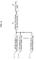
- a power estimation unit (power measurement unit) 30 includes non-serving cell power measurement units 31-1 to 31-n for each of non-serving cells #1 to #n, and an upper non-serving cell selection unit 32 that selects top m non-serving cells in the descending order of the measurement results by the non-serving cell power measurement units 31-1 to 31-n, and the number of block operations corresponding to the above-described serving cell correlation matrix calculation block 50-1 and the non-serving cell correlation matrix calculation block 50-2 may be controlled by according to the selection result.
- the above-described number of base stations may be predetermined based on the circuit scale or characteristics or the like, or may be adaptively changed.
- a reception power measurement may be executed for each base station.
- the correlation matrixes similar to the correlation matrix R 0 for the serving cell may be determined (that is, correlation value calculations are executed based on channel estimation values at the identical and different signal timings).
- the correlation matrix Q may be determined based on the channel estimation values for the identical signal timing from the view point of the power consumption since the other non-serving cells do not greatly contribute to an improvement in the receiver performance.
- a power estimation unit (power measurement unit) 30 includes non-serving cell power measurement units 31-1 to 31-n for each of non-serving cells #1 to #n, and a threshold non-serving cell selection unit 33 that selects non-serving cells having measurement results by the non-serving cell power measurement units 31-1 to 31-n of greater than or equal to a predetermined power threshold, and the number of block operations corresponding to the above-described serving cell correlation matrix calculation block 50-1 and the non-serving cell correlation matrix calculation block 50-2 may be controlled by according to the selection result.
- the value of the predetermined power threshold may be predetermined on the receiver performance, the power consumption or the like, or may be adaptively changed.
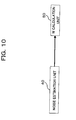
- the power measurement of interference components is executed by subtracting the signal component from the power measurement of the reception signal (signal component + interference component), only the thermal noise may be considered as the interference amount in this case since the noise estimation (noise calculation unit) 40 can determine the powers (estimation values) for all base stations (the serving cell and non-serving cells).
- the noise estimation unit 40 may determine the noise component ⁇ 2 I from Eq. (2.6) or (2.7), and provide it to the adder 57-1 depicted in FIG. 3 or FIG. 7 .
- the present invention at the weighted addition control (calculation of the tap coefficient) step at the equalizer, since the correlation matrix R 0 for the serving cell (first correlation value) is determined based on channel estimation values for all signal timings and the correlation matrix Q for the non-serving cell (second correlation value) is determined based solely on the channel estimation values at the identical signal timing, it is possible to improve the receiver performance, thereby reducing the effect of the interference wave from the non-serving cell while reducing the calculation amount. Accordingly, the present invention may be considered as quite useful in the technical field of wireless communication, especially, in the technical field in which reception signals are equalized by an equalizer.
Landscapes
- Engineering & Computer Science (AREA)
- Computer Networks & Wireless Communication (AREA)
- Signal Processing (AREA)
- Power Engineering (AREA)
- Mobile Radio Communication Systems (AREA)
- Cable Transmission Systems, Equalization Of Radio And Reduction Of Echo (AREA)
Abstract
Description
- The present invention relates to a control apparatus for and a control method of an equalizer, and a wireless terminal having such a control apparatus. The present invention is suitable for use in an apparatus (a wireless terminal, such as a wireless telephone, for example) including an equalizer that equalizes reception signals in a wireless environment in which radio waves may be received from multiple wireless base stations.
- In wireless communication technologies, such as cellular systems, equalizers are used as a technique for reducing multipath interferences. Equalizers are a technique for reducing interferences by calculating an appropriate synthesis (weighting) coefficient from estimation results of a propagation path (channel), and weighting-adding reception signals using the synthesis coefficient, thereby equalizing reception signals.
Here, for example, a signal y(t) after an equalizer at time t can be expressed using a reception signal x(t) and a synthesis coefficient (tap coefficient) w(i) according to the following Eq. (1.1): -

- How the synthesis coefficient w(t) is calculated determines characteristics of the equalizer and the processing amount.
Conventional equalizers either calculate the synthesis coefficient w based on the correlation matrix R0 only of the serving cell as expressed by the following Eq. (1.2) (seeNon-Patent References Reference 3 that will be listed later, for example). -


- In the above Eqs. (1.2) and (1.3), I represents the unit matrix, and σ2 represents the noise. In addition, a correlation matrix R can be calculated by the following Eq. (1.4) using the channel estimation value a(r, k) of the reception antenna number #r and the path number #k:
-

- Note that the term "correlation matrix R0 of the serving cell" refers to a matrix having, as an element, a correlation value based on a channel estimation value of an incoming signal (path) from a base station (serving cell) with which a wireless communication apparatus having an equalizer is communicating. The term "correlation matrix of a non-serving cell Ri" refers to a matrix having, as an element, a correlation value based on a channel estimation value of an incoming signal (path) from a base station (interference station) other than that serving cell (the definitions of the terms will be used throughout the specification).
- Note that well-known techniques regarding equalizers include the techniques described in the
Patent References
The technique inPatent Reference 1 is directed to provide a CDMA reception apparatus that experiences reduced deterioration of the receiver performance even when the number of concurrent users is increased in the DS/CDMA scheme during fast fading or in a multipath environment, and thus multiple interference elimination equalizers are provided for this purpose. Those interference elimination equalizer are adapted to regard multipath signal components at timings other than specified timing as signals from non-serving cells and eliminates such components, and to syntheses a multipath signal component only at the designated timing. - The technique in
Patent Reference 2 is directed to provide a noise power estimation apparatus that can estimate a chip noise power used for a weight calculation for an MMSE equalizer or the like. For this purpose, the apparatus is adapted to determine the noise power by eliminating multipath interference components from the reception power of the pilot signal for each path using the power ratio of pilot signal to data signal for each path, determining a modified reception power of the pilot signal for each path, estimating the total power of the pilot signal and the data signal included in the reception signal based on the modified reception power for the multiple paths and the predetermined power ratio, and subtracting the estimated total power from the total power of the reception signal. - Patent Reference 1: Japanese Laid-
Open Patent 1 Publication No.H07-30519 - Patent Reference 2: Japanese Laid-Open Patent Publication No.
2005-328311 - Non-Patent Reference 1: A. Klein, "Data Detection Algorithms Specially Designed for the Downlink of Mobile Radio Systems", Proc. of IEEE VTC'97, PP.203-207, Phoenix, May 1997
- Non-Patent Reference 2: 3GPP R4-040680, "HSDPA improvements for UE categories 7 and 8", Nokia, TSG RAN WG4#33, Nov 2004
- Non-Patent Reference 3: 3GPP R4-060514, "Reference structure for interference mitigation simulations with HSDPA and receiver diversity", Nokia, TSG RAN WG#39, May 2006
- However, in the case of determining the synthesis coefficient w based solely on the correlation matrix R0 of the serving cell (hereinafter, referred to as a Conventional Example 1), although the processing amount can be reduced, the receiver performance may be deteriorated since the interference components from non-serving cells cannot be reduced. On the other hand, in the case of determining the synthesis coefficient based on the correlation matrix R0 of the serving cell and correlation matrixes Ri of non-serving cells (hereinafter, referred to as a Conventional Example 2), the processing (calculation) amount is increased although the receiver performance is improved. That is, the calculation amount of twofold or higher is required compared to the case based solely on the correlation matrix R0 of the serving cell since a correlation matrixes R should be calculated for the serving cell and each of the non-serving cells.
- In addition, since the technique in
Patent Reference 1 inadvertently may eliminate multipath signal components at timings other than the specified timing since such components are mistaken as signals from non-serving cell and multipath signal components of the serving cell are accidentally eliminated, or conversely, multipath signal components of non-serving cells may be erroneously included into multipath signal components of the serving cell, which may deteriorate the receiver performance.
In addition, since the technique inPatent Reference 2 is a technique in which the noise power from the serving cell is measured highly accurately without taking multipath signal components from non-serving cells into consideration, the receiver performance may be degraded due to interferences from non-serving cells. - An object of the present invention is to reduce the calculation amount for determining a correlation matrix (correlation value) in a step for controlling the weighted addition in an equalizer (tap coefficient determination step).
In addition, another object of the present invention is to improve the receiver performance by reducing the effect of interferences by a signal from non-serving cell.
Note that it is an object of the present invention to provide advantages and effects that can be obtained by the best modes to implement the invention described below but cannot be obtained with conventional techniques. - In order to achieve the above-identified objects, the present invention is directed to use a control apparatus for and a control method of an equalizer, and a wireless terminal having such a control apparatus as described below:
- (1) A control apparatus for an equalizer of the present invention is a control apparatus for an equalizer that equalizes a reception signal by controlling a weighting-adding on a received sequence based on a correlation between a signal sent from a first wireless base station and an interference signal from a second wireless base station to the signal, the control apparatus including:
- (a) channel estimation unit that determines a channel estimation value regarding the first wireless base station based on a signal from the first wireless base station and determines a channel estimation value regarding the second wireless base station based on a signal from the second wireless base station;
- (b) correlation value calculation unit that determines, for the first wireless base station, a first correlation value based on a calculation result on channel estimation values having an identical signal timing and a calculation result on channel estimation values having different signal timings, and determines, for the second wireless base station, a second correlation value based on a calculation result on channel estimation values having an identical signal timing; and
- (c) weighting control unit that controls the weighting-adding at the equalizer based on the first and second correlation values determined by the correlation value calculation unit.
-
- (2) Here, the channel estimation unit may include: a first wireless base station channel estimation unit that determines a channel estimation value regarding the first wireless base station based on a pilot signal sent from the first wireless base station; and a second wireless base station channel estimation unit that determines a channel estimation value regarding the second wireless base station based on a pilot signal sent from the second wireless base station, and the correlation value calculation unit may include: a first wireless base station correlation value calculation unit that determines the first correlation value regarding the first wireless base station from a product of the channel estimation values determined by the first wireless base station channel estimation unit; and a second wireless base station correlation value calculation unit that determine the second correlation value regarding the second wireless base station from a product of channel estimation values, among the channel estimation values determined by the second wireless base station channel estimation unit, having an identical signal timing.
-
- (3) In addition, the control apparatus may further include power measurement unit that measures each reception power of signals of a plurality of the second wireless base stations, wherein the correlation value calculation unit may be configured to determine, for the second wireless base station that has the reception power equal to or greater than a predetermined power threshold, a second correlation value based on a calculation result on channel estimation values having an identical signal timing and a calculation result on channel estimation values having different signal timings, and determine, for the remaining second wireless base station, a second correlation value based on a calculation result on channel estimation values having an identical signal timing.
-
- (4) Furthermore, the control apparatus may further include power measurement unit that measures each reception power of signals of a plurality of the second wireless base stations, wherein the correlation value calculation unit may be configured to determine, for a predetermined number of second wireless base stations selected by the descending order of the reception power from the highest, a second correlation value based on a calculation result on channel estimation values having an identical signal timing and a calculation result on channel estimation values having different signal timings, and determine, for the remaining second wireless base station, a second correlation value based on a calculation result on channel estimation values having an identical signal timing.
-
- (5) In addition, the control apparatus may further include noise calculation unit that determines a thermal noise based on a temperature, wherein the weighting control unit may be configured to control the weighting-adding based on each correlation value and the thermal noise determined by the noise calculation unit.
- (6) Furthermore, the wireless terminal of the present invention includes any one of the control apparatuses for an equalizer according to the above (1) to (5).
-
- (7) In addition, a control method of an equalizer of the present invention is a control method of an equalizer that equalizes a reception signal by controlling a weighting-adding on a received sequence based on a correlation between a signal sent from a first wireless base station and an interference signal from a second wireless base station to the signal, the method including:
- (a) a channel estimation step that determines a channel estimation value regarding the first wireless base station based on a signal from the first wireless base station and determines a channel estimation value regarding the second wireless base station based on a signal from the second wireless base station;
- (b) a correlation value calculation step that determines, for the first wireless base station, a first correlation value based on a calculation result on channel estimation values having an identical signal timing and a calculation result on channel estimation values having different signal timings, and determines, for the second wireless base station, a second correlation value based on a calculation result on channel estimation values having an identical signal timing; and
- (c) a weighting control step that controls the weighting-adding at the equalizer based on the first and second correlation values determined at the correlation value calculation step.
-
- (8) Here, the channel estimation step may include:
- determining a channel estimation value regarding the first wireless base station based on a pilot signal sent from the first wireless base station and determining a channel
- estimation value regarding the second wireless base station based on a pilot signal sent from the second wireless base station, and the correlation value calculation step may
- include: determining the first correlation value regarding the first wireless base station from a product of the channel estimation values regarding the first wireless base station and determining the second correlation value regarding the second wireless base station from a product of channel
- estimation values among the channel estimation values
- regarding the second wireless base station having an
- identical signal timing.
-
- (9) In addition, the control method may further include measuring each reception power of signals of a plurality of the second wireless base stations, wherein the correlation value calculation step may include: determining, for the second wireless base station that has the reception power equal to or greater than a predetermined power threshold, a second correlation value based on a calculation result on channel estimation values having an identical signal timing and a calculation result on channel estimation values having different signal timings, and determining, for the remaining second wireless base station, a second correlation value based on a calculation result on channel estimation values having an identical signal timing.
-
- (10) Furthermore, the control method may further include measuring each reception power of signals of a plurality of the second wireless base sations, wherein the correlation value calculation step may include: determining, for a predetermined number of second wireless base stations selected by the descending order of the reception power from the highest, a second correlation value based on a calculation result on channel estimation values having an identical signal timing and a calculation result on channel estimation values having different signal timings, and determining, for the remaining second wireless base station, a second correlation value based on a calculation result on channel estimation values having an identical signal timing.
-
- (11) In addition, the control method may further include determining a thermal noise based on a temperature, wherein the weighting control step may include: controlling the weighting-adding based on each correlation value and the thermal noise determined.
- According to the present invention, it is possible to reduce the amount of correlation calculation required for controlling the weighted addition in an equalizer.
In addition, according to the present invention, it is possible to improve the receiver performance by reducing the effect of interferences by signals from non-serving cell. -
-
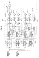
FIG. 1 is a block diagram illustrating a configuration of the main portion of a wireless receiver according to one embodiment of the present invention; -
FIG. 2 is a block diagram illustrating a configuration of an FIR filter unit depicted inFIG. 1 ; -
FIG. 3 is a block diagram illustrating a pilot channel (CPICH) despreading unit and a weight calculation unit depicted inFIG. 1 ; -
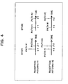
FIG. 4 is a drawing schematically illustrating an example of the reception environment (multipath signals incoming to the reception antenna) of the wireless reception apparatus depicted inFIGS. 1-3 ; -
FIG. 5 is a diagram illustrating one example of an correlation matrix determined by the serving cell correlation matrix calculation block depicted inFIG. 3 in the reception environment depicted inFIG. 4 ; -
FIG. 6 is a diagram illustrating one example of an correlation matrix determined by the non-serving cell correlation matrix calculation block depicted inFIG. 3 in the reception environment depicted inFIG. 4 ; -
FIG. 7 is block diagram illustrating a first variation of the wireless receiver depicted inFIGS. 1-3 ; -
FIG. 8 is block diagram illustrating a second variation of the wireless receiver depicted inFIGS. 1-3 ; -
FIG. 9 is block diagram illustrating a third variation of the wireless receiver depicted inFIGS. 1-3 ; and -
FIG. 10 is block diagram illustrating a fourth variation of the wireless receiver depicted inFIGS. 1-3 . -
- 11, 12
- Pilot Channel (CPICH) Despreading unit
- 11-1, 12-1
- Serving Cell Code Despreading unit
- 11-2, 11-3, 12-2, 12-3
- Non-serving Cell Code Despreading unit
- 20
- Equalizer (FIR Filtering unit)
- 21
- Delay Circuit
- 22
- Tap Multiplier
- 23
- Addition Circuit (∑)
- 30
- Power Estimation (Power Measurement unit)
- 31-1 to 31-N
- Non-serving Cell power measurement unit
- 32
- Upper Non-serving Cell Selection unit
- 33
- Threshold Non-serving Cell selection unit
- 40
- Noise Estimation (Noise Calculation unit)
- 50
- Weight (W) Calculation unit (Correlation Value Calculation unit, Weighting Control unit)
- 50-1
- serving cell Correlation Matrix Calculation Block (First Wireless Base Station Correlation Value Calculation unit)
- 50-2
- Non-serving Cell Correlation Matrix Calculation Block (Second Wireless Base Station Correlation Value Calculation unit)
- 50-3
- Non-serving Cell Correlation Matrix Calculation Block
- 51-1 to 51-6
- Averaging Calculation unit
- 52-1, 52-2, 52-5, 52-6
- Timing Delay Circuit
- 53-1, 53-2, 55-1 to 55-5
- Complex Multiplier
- 54-1 to 54-3, 56-1 to 56-6, 57-1 to 57-8
- Adder
- 58
- Matrix Calculation unit
- 60
- Window Timing Control unit
- 70
- Data Despreading unit
- Hereinafter, embodiments of the present invention will be described with reference to the drawings. Note that the embodiments described below are described by way of example only for ease of understanding of the concept of the present invention, and various modifications and technical applications that are not provided explicitly in the following embodiments are not intended to be excluded. In other words, any modifications and applications of techniques to the present invention are within the spirit of the present invention and are apparent to those ordinally skilled in the art (skilled artisans), and are naturally within the scope technological scope of the present invention.
-
- (A) Description of One Embodiment
FIG. 1 is a block diagram illustrating the main portion of a wireless reception apparatus according to one embodiment of the present invention. The wireless reception apparatus depicted inFIG. 1 can be employed as a reception system of a wireless terminal (MS), such as a wireless telephone, for example, and is configured to include twoantennas # 1 and #2, common pilot channel (CPICH) despreading unit s 11 and 12 for theantennas # 1 and #2, respectively, an equalizer (FIR filtering unit) 20, apower estimation unit 30, anoise estimation unit 40, a weight (W)calculation unit 50, a windowtiming control unit 60, and adata despreading unit 70. Note that the control apparatus of theequalizer 20 comprises thepower estimation unit 30, thenoise estimation unit 40, the weight (W)calculation unit 50, and the windowtiming control unit 60, for example. - Here, the CPICH despreading unit (channel estimation unit) 11 is adapted to determine channel estimation values of each of common pilot signals from the serving cell (first wireless base station) and a non-serving cell (second wireless base station) by despreading signals received at one
antenna # 1 using a code of the serving cell (transmission station that is a serving cell) and a code of the non-serving cell (interference station, the station that sends signals that interfere with reception signals from the serving cell) . The CPICH despreading unit (channel estimation unit) 12 is adapted to determine channel estimation values of each of common pilot signals from the serving cell and the non-serving cell by similarly despreading signals received at theother antenna # 2 using the code of the serving cell and the code of the non-serving cell. - The
FIR filtering unit 20 is adapted to equalize the above reception data (FIR filtering) for the purpose of reducing multipath interferences, and is configured to include n delay circuits 21 (n is an integer equal to or greater than 2) that delay input reception data by a unit time (one chip), andn tap multipliers 22 that multiply the outputs from thedelay circuits 21 by tap coefficients w0, w1, ..., wn-1, and an addition circuit (∑) 23 that adds the outputs from the tap multipliers 22 (determines the total sum). - The window
timing control unit 60 is adapted to control the number of tap coefficients w (the window timings for determining the window width) for the filtering at theFIR filtering unit 20 based on the despreading results from each of the CPICH despreading unit s 11 and 12. Thedata despreading unit 50 is adapted to despread the output of theFIR filtering unit 20 to obtain the demodulation result.
Thepower estimation unit 30 is adapted to estimate the reception power based on the despreading results from each of theCPICH despreading units noise estimation unit 40 is adapted to determine the noise estimation value (ρ2I). Note that thepower estimation unit 30 has a function that is required for variants that will be described later, and thus may be omitted in this embodiment. - The weight calculation unit (correlation value calculation unit, weighting control unit) 50 is adapted to determine each correlation matrix for the serving cell and the non-serving cell based on the estimation values from the
estimation units CPICH despreading units tap multiplier 22 in theFIR filtering unit 20 from these correlation matrixes. In this example, the calculation amount can be reduced using a simplified matrix Q in which correlation values are calculated only for signals incoming to theantennas # 1 and #2 at the same timing and remaining components are set to zero, rather than determining the correlation matrix of the non-serving cell using a calculation similar to the calculation used for determining the correlation matrix R0 of the serving cell. - That is, the
weight calculation unit 50 in this example is adapted to determine the correlation matrix (first correlation value) R0 for the serving cell and the correlation matrix (second correlation value) Q for the non-serving cell according to the calculations expressed by the following Eqs. (2.2) and (2.3), and determine the tap coefficient w from these synthesis matrixes R using the following Eq. (2.1). Note that it is assumed that the matrixes R0, Q, and R are all matrix having i rows and j columns, and that the channel estimation value of the antenna number #r (r1, r2) and the path number #m is expressed as Y(r, m). -


- where δ (x, y) represents a Kronecker delta, which is 1 when x = y or 0 when x ≠ y in Eq. (2.3).
For example, as depicted inFIG. 4 , assume the case in which, in the reception environment in which signals arrive at theantenna # 1 and #2 from the wireless base station (BTS) #1 through twopaths # 1 and #2, respectively, and signals also arrive at theantenna # 1 and #2 from theBTS # 2 through twopaths # 1 and #2, respectively, only the signals from theBTS # 1 are received as effective signals (the signals from theBTS # 2 are interference waves). - For this example, the correlation matrix R0 for the BTS #1 (serving cell) is illustrated in
FIG. 5 , and the correlation matrix Q for the BTS #2 (non-serving cell) is illustrated inFIG. 6 . The tap coefficient w is determined based on the matrix depicted inFIG. 5 in Conventional Example 1 while the tap coefficient w is determined by calculating matrixes depicted inFIG. 5 for each of theBTSs # 1 and #2 in Conventional Example 2 so as to improve the receiver performance. In this example, the receiver performance is improved while reducing the calculation amount by determining the simplified matrix Q depicted inFIG. 6 as a correlation matrix for theBTS # 2. - For this purpose, the wireless reception apparatus in this example is configured to include a serving cell code despreading unit 11-1 and a non-serving cell code despreading unit 11-2 as the above-described
CPICH despreading unit 11, as well as including a serving cell code despreading unit 12-1 and a non-serving cell code despreading unit 12-2 as the above-describedCPICH despreading unit 12, as depicted inFIG. 3 , for example.
In addition, theweight calculation unit 50 is configured to include common pilot despreading units 51-1 to 51-4, averaging calculation units 51-1 to 51-4, timing delay circuits 52-1 and 52-2, square circuits 52-3 and 52-4, complex multipliers 53-1 and 55-1 to 55-3, adders 54-1, 54-2, 56-1 to 56-4, and 57-1 to 57-5, and amatrix calculation unit 58, as depicted inFIG. 3 , for example. - The block illustrated in the dotted line rectangle 50-1, that is, the block having the averaging calculation units 51-1 and 51-2, the timing delay circuits 52-1 and 52-2, the complex multipliers 53-1, 55-1, and 55-2, the adders 54-1, 56-1, 56-2, and 57-1 to 57-3 functions as a serving cell correlation matrix calculation block (first wireless base station correlation value calculation unit) that determines the correlation matrix R0 for the serving cell (BTS #1). The block illustrated in dotted line rectangle 50-2, that is, the block having the averaging calculation units 51-3 and 51-4, the square circuits 52-3 and 52-4, the complex multiplier 55-3, the adder 56-3, 54-2, 56-4, 57-4, and 57-5 functions as a non-serving cell correlation matrix calculation block (second wireless base station correlation value calculation unit) that determine the correlation matrix Q for the non-serving cell (BTS #2).
- Here, the serving cell code despreading unit (first wireless base station channel estimation) 11-1 is adapted to determine the channel estimation value between one
reception antenna # 1 and theBTS # 1 by despreading reception data (common pilot signal) for thereception antenna # 1 using the code of the serving cell (BTS #1). The non-serving cell code despreading unit (second wireless base station channel estimation) 11-2 is adapted to determine the channel estimation value between thereception antenna # 1 and theBTS # 2 by despreading the reception data (common pilot signal) for thereception antenna # 1 using the code of the non-serving cell (BTS #2). - Here, the serving cell code despreading unit (first wireless base station channel estimation) 12-1 is adapted to determine the channel estimation value between the other
reception antenna # 2 and theBTS # 1 by despreading the reception data (common pilot signal) for thereception antenna # 2 using the code of the serving cell. The non-serving cell code despreading unit (second wireless base station channel estimation) 12-2 is adapted to determine the channel estimation value between thatreception antenna # 2 and theBTS # 2 by despreading the reception data (common pilot signal) for thereception antenna # 2 using the code of the non-serving cell. - Furthermore, in the
weight calculation unit 50, the averaging calculation units 51-1 and 51-2 are adapted to average the despreading results (the channel estimation value with the BTS #1) from corresponding despreading units 11-1 and 12-1, respectively. The timing delay circuits 52-1 and 52-2 are adapted to delay the average values of the channel estimation values obtained at the averaging calculation units 51-1 and 51-2 (average channel estimation values) by (i-j) (when assuming that the correlation matrix R0 for the serving cell is a matrix having i rows and j columns) and output delayed values to the complex multipliers 55-1 and 55-2, respectively. - The complex multiplier 55-1 is adapted to complex-multiply the output from the timing delay circuit 52-1 by the outputs from the averaging calculation units 51-1 and 51-2. This complex multiplication corresponds to, when taking the reception status depicted in
FIG. 4 as an example, determining the 7 x 7 block element (correlation values S, 0, α1 *β1, and β1 *α1) of the upper left (the antenna #1-the antenna #1) of the matrix R0 depicted inFIG. 5 by multiplying one of the channel estimation value α1 and β1 of thepaths # 1 and #2 that reach at oneantenna # 1 as a conjugate complex number with the timing deviated by (i-j) with the other of α1 and pal. - Similarly, the complex multiplier 55-2 is adapted to complex-multiply the output from the timing delay circuit 52-2 by the outputs from the averaging calculation units 51-2 and 51-2. This complex multiplication corresponds to, when taking the reception status depicted in
FIG. 4 as an example, determining the 7 x 7 block element (correlation values S, 0, a2 *β2, and β2 *α2) of the lower right (the antenna #2-the antenna #2) of the matrix R0 depicted inFIG. 5 by multiplying one of the channel estimation value α2 and β2 of thepaths # 1 and #2 that reach at theother antenna # 2 with the timing deviated by (i-j) as a conjugate complex number with the other of α2 and β2. - Note that S = |α1|2 + |α2|2 + |β1|2 + |β2|2 and, among the addition elements, the elements of |α1|2 and |β1|2 are obtained as a calculation result from one complex multiplier 55-1 when i = j, and the elements of |α2|2 and |β2|2 are obtained as a calculation result of the other complex multiplier 55-2 when i = j. That is, each addition component of the above S is obtained as the complex multiplication result between the channel estimation values when signals from the
different paths # 1 and #2 reach at thesame antenna # 1 or #2 at the same timing. - The complex multiplier 53-1 is adapted to complex-multiply the outputs from the averaging calculation units 51-1 by the output from the timing delay circuit 52-2. This complex multiplication corresponds to, when taking the reception status depicted in
FIG. 4 as an example, determining 7 x 7 block elements (correlation values C*, 0, α2 *β1, β2 *α1, α1 *β2, and β1 *α2) of the lower left and the upper right (the antenna #1-theantenna # 2 and the antenna #2-the antenna #1) of the matrix R0 depicted inFIG. 5 by multiplying one of the channel estimation value α1 and β2 of thepaths # 1 and #2 that reach at each of theantennas # 1 and #2 with the timing deviated by (i-j) and the channel estimation value α2 and β1 with the other as a conjugate complex numbers, respectively. Note that C* = α1 *α2 + β1 *β2, and α1 *α2 and β1 *β2 are the calculation results from the complex multiplier 53-1 when i = j, that is, they are obtained as the complex multiplication results between the channel estimation values when signals from thesame path # 1 or #2 reach at thedifferent antennas # 1 and #2 at the same timing. - The adder 56-1 is adapted to determine the 7 x 7 block on the upper left of the matrix R0 depicted in
FIG. 5 by cumulatively adding outputs from the complex multiplier 55-1. Similarly, the adder 56-2 is adapted to determine the 7 x 7 block on the lower right of the matrix R0 depicted inFIG. 5 by cumulatively adding outputs from the complex multiplier 55-2. The adder 54-1 is adapted to determine the 7 x 7 blocks on the lower left and upper right of the matrix R0 depicted inFIG. 5 by cumulatively adding outputs from the complex multiplier 53-1. - The adders 57-1, 57-2, and 57-3 are adapted to determine the correlation matrix R0 depicted in
FIG. 5 for the serving cell (BTS #1) by adding (synthesizing) the addition results (block elements) from the respective adders 56-1, 54-1, and 56-2, respectively.
On the other hand, the averaging calculation units 51-3 and 51-4 are adapted to average the despreading results (the channel estimation values with the BTS #2) from corresponding despreading units 11-2 and 12-2, respectively. The square circuits 52-3 and 52-4 are adapted to square the outputs from the corresponding averaging calculation units 51-3 and 51-4, respectively. The squares corresponds to, when taking the reception status depicted inFIG. 4 as an example, determining the 7 x 7 block elements (diagonal elements) S1 on the upper left and lower right (the antenna #1-theantenna # 1 and the antenna #2-the antenna #2) of the matrix Q depicted inFIG. 6 by complex-multiply channel estimation values when signals from thedifferent paths # 1 and #2 reach at thesame antenna # 1 or #2 at same timing (when i = j). Note that S1 = |γ1|2 + |γ2|2 + |δ1|2 + |δ2|2, and, among the addition elements, the elements of |γ1|2 and |δ1|2 are obtained as the calculation result from the square circuit 52-3, and the elements of |γ2|2 and |δ2|2 are obtained as the calculation result from the square circuit 52-4. - The complex multiplier 55-3 is adapted to complex-multiply the output of each of the above-described averaging calculation units 51-3 and 51-4. This complex multiplication corresponds to, when taking the reception status depicted in
FIG. 4 as an example, determining the addition components γ1 *γ2 and δ1 *δ2 of each of 7 × 7 block elements (diagonal elements) C1 and C1 * (C1 = γ1 *γ2 + δ1 *δ2) on the lower left and upper right (the antenna #1-theantenna # 2, the antenna #2-the antenna #1) of the matrix Q depicted inFIG. 5 by multiplying one of the channel estimation values from thesame path # 1 or #2 reaching at thedifferent antennas # 1 and #2 at same timing (when i = j) as a conjugate complex number with the other channel estimation value. - In addition, the adder 56-3 is adapted to determine each of the upper left and lower right blocks of the matrix Q depicted in
FIG. 6 by cumulatively adding outputs from the complex multiplier 55-3. The square circuits 52-3 and 52-4 are adapted to determine each of lower left and upper right blocks of the matrix Q depicted inFIG. 6 by cumulatively adding respective outputs from the adder 54-2 and 56-4, respectively.
In addition, the adders 57-4 and 57-5 are adapted to determine the matrix Q for the non-serving cell (BTS #2) depicted inFIG. 6 expressed by Eq. (2.3) described above by adding the addition results (block elements) from the adders 56-3, 54-2, and 56-4, wherein the synthesis matrix R expressed by Eq. (2.2) described above is determined by adding (synthesizing) the matrix Q with the matrix R0 and the noise estimation value ρ2I through the adders 57-1 to 57-3. - Finally, the
matrix calculation unit 58 is adapted to determine the tap coefficient w by resolving the above-described Eq. (2.3) based on the synthesis matrix R and the channel estimation value h obtained as outputs of the serving cell code despreading units 11-1 and 12-1 described above, and to provide the tap coefficient w to thetap multiplier 22 of theFIR filtering unit 20.
Hereinafter, the operation (tap coefficient calculation method) of the wireless reception apparatus that is configured as described above according to this embodiment will be described when assuming the reception environment depicted inFIG. 4 . Signals at theBTSs # 1 and #2 arrive at thereception antennas # 1 and #2, respectively, and the channel estimation values for theBTSs # 1 and #2 are obtained by despreading each of the reception signals at theantennas # 1 and #2 by means of the CPICH despreading unit 11 (the serving cell code despreading unit 11-1, the common pilot despreading unit 51-2), the CPICH despreading unit 12 (the serving cell code despreading unit 12-1, the common pilot despreading unit 52-2) using the spreading codes for the common pilot signals of theBTSs # 1 and #2 (channel estimation step). - The
weight calculation unit 50 is adapted to determine the correlation matrixes R (the matrixes R0 and Q) using the thus obtained channel estimation values to determine the tap coefficient w.
More specifically, for the channel estimation values determined by the serving cell code despreading units 11-1 and 12-1 for each of theantennas # 1 and #2, and at the above-described timing delay circuits 52-1 and 52-2, the complex multipliers 53-1, 55-1, and 55-2, the adders 54-1, 56-1, 56-2, and 57-1 to 57-3, the correlation matrix R0 for the serving cell is determined by multiplying one of the channel estimation values having the timing difference (i-j) as a conjugate complex number with the other channel estimation value and executing this operation for all timings (identical and different signal timings) at which the channel estimation values are determined as described above ((serving cell) correlation value calculation step). - That is, assuming that the channel estimation value is X(r, m) for the antenna number #r (r1, r2), and path number #m, the correlation matrix Ri,j = R0 having i rows and j columns is calculated by the following Eq. (2.4) as depicted in
FIG. 5 . Note that in the case of the reception environment depicted inFIG. 4 , the values corresponds to X(1, 1) = α1, X(1, 2) = β1, X(2, 1) = α2, and X(2, 2) = β2. -

- On the other hand, for the channel estimation valued determined by the common pilot despreading units 51-2 and 12-2 for each
antenna # 1 or #2, in order to reduce the calculation amount, channel estimation values without timing difference (at the identical signal timing) are multiplied at the averaging calculation units 51-3 and 51-4, the square circuits 52-3 and 52-4, the complex multiplier 55-3, the adder 54-2, 56-3, 56-4, 57-4, and 57-5 as described above (for thesame antenna # 1 or #2, a square sum is taken at the square circuits 52-3 and 52-4). That is, for an antenna number #r, the matrix Q for the non-serving cell is calculate according to the following Eq. (2.5) using the channel estimation value Y (r, k) for the path number #k ((non-serving cell) correlation value calculation step). -

- Then, the synthesis matrix R is determined by adding, through the adders 57-1 to 57-5, the matrix R0 and the matrix Q calculated as described above, and the noise estimation value ρ2I determined at the
noise estimation unit 40, and is entered to thematrix calculation unit 58.
Thematrix calculation unit 58 thus determines the tap coefficient w by resolving the above-described Eq. (2.1) based on the synthesis matrix R and the channel estimation value for the serving cell (the despreading results from the serving cell code despreading units 11-1 and 12-1), and provides the tap coefficient w to each of thetap multipliers 22 in the FIR filtering unit 20 (weighting control step). - As described above, according to this embodiment, at the weighted addition control (calculation of the tap coefficient w) step at the equalizer (the FIR filtering unit 20), since the correlation matrix R0 for the serving cell (correlation value) is determined based on channel estimation values for all signal timings and the correlation matrix Q for the non-serving cell (correlation value) is determined based solely on the channel estimation values at the identical signal timing, it is possible to improve the receiver performance, thereby reducing the effect of the interference wave from the non-serving cell while reducing the calculation amount.
- For example, since an increase in the calculation amount in this example compared to Conventional Example 1 is proportional to the inverse of the square of the number of taps (the number of synthesis coefficients) per antenna, suppose that the number of the BTSs is 2 and the number of taps per antenna is 40, the technique of this example can be achieved with an about 1.3% increase in the calculation amount compared to Conventional Example 1. Note that Conventional Example 2 will require the calculation amount of twofold (a 100% increase).
- The correlation matrix Q for the non-serving cell is calculated based solely on the channel estimation values for the identical signal timing in the above-described embodiment. However, similar to the correlation matrix for the serving cell, the correlation matrix may be calculated based on channel estimation values at all signal timings for a non-serving cell to which signals having a power greater than a predetermined power threshold are incoming (such a non-serving cells is called as a "non-serving cell having a greater power," and other non-serving cells are called "non-serving cells having smaller power").
- For example, the configuration corresponding to
FIG. 3 is illustrated inFIG. 7 in which signals are incoming from anon-serving cell # 1 having a greater power and anon-serving cell # 2 having a greater smaller, other than signals from the serving cell. The wireless reception apparatus depicted inFIG. 7 is different from the configuration illustrated inFIG. 3 in that it further includes a code despreading unit 11-3 that determines a channel estimation value by despreading a reception signal at theantenna # 1 using the spreading code of the common pilot signal of thenon-serving cell # 1 and a non-serving cell code dispreading unit 12-3 that determine a channel estimation value by despreading a reception signal at theantenna # 2 using the spreading code of the common pilot signal of thenon-serving cell # 1, and that a non-serving cell correlation matrix calculation block 50-3 that has the configuration similar to the serving cell correlation matrix calculation block 50-1 is added for thenon-serving cell # 1 having a greater power and a non-serving cell correlation matrix calculation block 50-2 that determines the correlation matrix Q corresponds to thenon-serving cell # 2 having a smaller power. - That is, the non-serving cell correlation matrix calculation block 50-3 is configured to include averaging calculation units 51-5 and 51-6, timing delay circuits 52-5 and 52-6, the complex multipliers 53-2, 55-4, and 55-5, and adders 54-3, 56-5, 56-6, and 57-6 to 57-8, similar to the components in the serving cell correlation matrix calculation block 50-1.
In addition, in this case, in the non-serving cell correlation matrix calculation block 50-2, the non-serving cell code dispreading unit 11-2 is adapted to determine the channel estimation value by despreading a reception signal at theantenna # 1 using the spreading code of the common pilot signal of thenon-serving cell # 2. The non-serving cell code dispreading unit 12-2 is adapted to determine the channel estimation value by despreading reception signal at theantenna # 2 using the spreading code of the common pilot signal of thenon-serving cell # 2. - In the wireless reception apparatus that is configured as described above, even being non-serving cells, for the
non-serving cell # 1 having a greater power which has a power estimation value obtained at the powerestimation value unit 30 of a predetermined power threshold or greater, the correlation matrix is determined at the non-serving cell correlation matrix calculation block 50-3 based on channel estimation values at the identical and different signal timings similar to the above-described serving cell correlation matrix calculation block 50-1, and for thenon-serving cell 2 having a smaller power, the correlation matrix Q is determined at the non-serving cell correlation matrix calculation block 50-2 based solely on channel estimation values without signal timing difference, similar to the above-described embodiment. - The tap coefficient w is determined according to the above Eq. (2.1) at the
matrix calculation unit 58 based on the synthesis matrix R of the correlation matrixes determined at each of the correlation matrix calculation blocks 50-1, 50-2, and 50-3 for each of the serving cell and twonon-serving cells # 1 and #2.
As described above, according to this variant, even for non-serving cells, since a further accurate correlation value calculations are executed based on channel estimation values at the identical and different signal timings for non-serving cells that have greater reception powers and larger amounts of interferences, it is possible to further improve the receiver performance by eliminating interference components from non-serving cells having greater reception powers, as compared to the above-described embodiment. - (C) Description of Second Variant Note that when there are three or more non-serving cells, a reception power measurement may be executed for each base station, and the correlation matrixes similar to the correlation matrix R0 for the serving cell may be determined (that is, correlation value calculations are executed based on channel estimation values at the identical and different signal timings) for a predetermined number of base stations that are selected according to in the descending order of the power. The correlation matrixes Q may be determined for other non-serving cells based solely on the channel estimation values for the identical signal timing.
- In this case, for example, as depicted in
FIG. 8 , a power estimation unit (power measurement unit) 30 includes non-serving cell power measurement units 31-1 to 31-n for each ofnon-serving cells # 1 to #n, and an upper non-servingcell selection unit 32 that selects top m non-serving cells in the descending order of the measurement results by the non-serving cell power measurement units 31-1 to 31-n, and the number of block operations corresponding to the above-described serving cell correlation matrix calculation block 50-1 and the non-serving cell correlation matrix calculation block 50-2 may be controlled by according to the selection result. - By configuring as described above, even when there are three or more non-serving cells, it is possible to eliminate interference components from the non-serving cells having greater reception powers, thereby further improving the receiver performance. Note that the above-described number of base stations may be predetermined based on the circuit scale or characteristics or the like, or may be adaptively changed.
- In addition, when there are three or more non-serving cells, a reception power measurement may be executed for each base station. For base stations having power equal to or greater than a predetermined power threshold, the correlation matrixes similar to the correlation matrix R0 for the serving cell may be determined (that is, correlation value calculations are executed based on channel estimation values at the identical and different signal timings). For other non-serving cells, the correlation matrix Q may be determined based on the channel estimation values for the identical signal timing from the view point of the power consumption since the other non-serving cells do not greatly contribute to an improvement in the receiver performance.
- In this case, for example, as depicted in
FIG. 9 , a power estimation unit (power measurement unit) 30 includes non-serving cell power measurement units 31-1 to 31-n for each ofnon-serving cells # 1 to #n, and a threshold non-servingcell selection unit 33 that selects non-serving cells having measurement results by the non-serving cell power measurement units 31-1 to 31-n of greater than or equal to a predetermined power threshold, and the number of block operations corresponding to the above-described serving cell correlation matrix calculation block 50-1 and the non-serving cell correlation matrix calculation block 50-2 may be controlled by according to the selection result. - This provides the effects similar to those of the above second variant, and also further simplify and increase the speed of the non-serving cell selection operation. Note that the value of the predetermined power threshold may be predetermined on the receiver performance, the power consumption or the like, or may be adaptively changed.
- Although, generally, the power measurement of interference components is executed by subtracting the signal component from the power measurement of the reception signal (signal component + interference component), only the thermal noise may be considered as the interference amount in this case since the noise estimation (noise calculation unit) 40 can determine the powers (estimation values) for all base stations (the serving cell and non-serving cells).
- The calculation of the thermal noise may be executed by the following Eq. (2.6) using the temperature T and the Boltzmann constant K.

In addition, considering the noise figure (NF) of the wireless reception apparatus, the thermal noise may also be determined as follows:
- Accordingly, as depicted in
FIG. 10 , thenoise estimation unit 40 may determine the noise component ρ2I from Eq. (2.6) or (2.7), and provide it to the adder 57-1 depicted inFIG. 3 orFIG. 7 . - As described above in detail, according to the present invention, at the weighted addition control (calculation of the tap coefficient) step at the equalizer, since the correlation matrix R0 for the serving cell (first correlation value) is determined based on channel estimation values for all signal timings and the correlation matrix Q for the non-serving cell (second correlation value) is determined based solely on the channel estimation values at the identical signal timing, it is possible to improve the receiver performance, thereby reducing the effect of the interference wave from the non-serving cell while reducing the calculation amount. Accordingly, the present invention may be considered as quite useful in the technical field of wireless communication, especially, in the technical field in which reception signals are equalized by an equalizer.
Claims (11)
- A control apparatus for an equalizer that equalizes a reception signal by controlling a weighting-adding on a received sequence based on a correlation between a signal sent from a first wireless base station and an interference signal from a second wireless base station to the signal, the control apparatus comprising:channel estimation unit that determines a channel estimation value regarding the first wireless base station based on a signal from the first wireless base station and determines a channel estimation value regarding the second wireless base station based on a signal from the second wireless base station;correlation value calculation unit that determines, for the first wireless base station, a first correlation value based on a calculation result on channel estimation values having an identical signal timing and a calculation result on channel estimation values having different signal timings, and determines, for the second wireless base station, a second correlation value based on a calculation result on channel estimation values having an identical signal timing;
andweighting control unit that controls the weighting-adding at the equalizer based on the first and second correlation values determined by the correlation value calculation unit. - The control apparatus for an equalizer according to claim 1, whereinthe channel estimation unit comprises:a first wireless base station channel estimation unit that determines a channel estimation value regarding the first wireless base station based on a pilot signal sent from the first wireless base station; anda second wireless base station channel estimation unit that determines a channel estimation value regarding the second wireless base station based on a pilot signal sent from the second wireless base station, andthe correlation value calculation unit comprises:a first wireless base station correlation value calculation unit that determines the first correlation value regarding the first wireless base station from a product of the channel estimation values determined by the first wireless base station channel estimation unit; anda second wireless base station correlation value calculation unit that determine the second correlation value regarding the second wireless base station from a product of channel estimation values, among the channel estimation values determined by the second wireless base station channel estimation unit, having an identical signal timing.
- The control apparatus for an equalizer according to claim 1 or 2, further comprising power measurement unit that measures each reception power of signals of a plurality of the second wireless base stations,
wherein the correlation value calculation unit is configured to determine, for the second wireless base station that has the reception power equal to or greater than a predetermined power threshold, a second correlation value based on a calculation result on channel estimation values having an identical signal timing and a calculation result on channel estimation values having different signal timings, and determine, for the remaining second wireless base station, a second correlation value based on a calculation result on channel estimation values having an identical signal timing. - The control apparatus for an equalizer according to claim 1 or 2, further comprising power measurement unit that measures each reception power of signals of a plurality of the second wireless base stations,
wherein the correlation value calculation unit is configured to determine, for a predetermined number of second wireless base stations selected by the descending order of the reception power from the highest, a second correlation value based on a calculation result on channel estimation values having an identical signal timing and a calculation result on channel estimation values having different signal timings, and determine, for the remaining second wireless base station, a second correlation value based on a calculation result on channel estimation values having an identical signal timing. - The control apparatus for an equalizer according to any one of claims 1 to 4, further comprising noise calculation unit that determines a thermal noise based on a temperature,
wherein the weighting control unit is configured to control the weighting-adding based on each correlation value and the thermal noise determined by the noise calculation unit. - A wireless terminal comprising the control apparatus for an equalizer according to any one of claims 1 to 5.
- A control method of an equalizer that equalizes a reception signal by controlling a weighting-adding on a received sequence based on a correlation between a signal sent from a first wireless base station and an interference signal from a second wireless base station to the signal, the method comprising:a channel estimation step that determines a channel estimation value regarding the first wireless base station based on a signal from the first wireless base station and determines a channel estimation value regarding the second wireless base station based on a signal from the second wireless base station;a correlation value calculation step that determines, for the first wireless base station, a first correlation value based on a calculation result on channel estimation values having an identical signal timing and a calculation result on channel estimation values having different signal timings, and determines, for the second wireless base station, a second correlation value based on a calculation result on channel estimation values having an identical signal timing;
anda weighting control step that controls the weighting-adding at the equalizer based on the first and second correlation values determined at the correlation value calculation step. - The control method of an equalizer according to claim 7, wherein the channel estimation step comprises:determining a channel estimation value regarding the first wireless base station based on a pilot signal sent from the first wireless base station and determining a channelestimation value regarding the second wireless base station based on a pilot signal sent from the second wireless base station, andthe correlation value calculation step comprises: determining the first correlation value regarding the first wireless base station from a product of the channel estimation values regarding the first wireless base station and determining the second correlation value regarding the second wireless base station from a product of channel estimation values among the channel estimation values regarding the second wireless base station having an identical signal timing.
- The control method of an equalizer according to claim 7 or 8, further comprising measuring each reception power of signals of a plurality of the second wireless base stations,
wherein the correlation value calculation step comprises: determining, for the second wireless base station that has the reception power equal to or greater than a predetermined power threshold, a second correlation value based on a calculation result on channel estimation values having an identical signal timing and a calculation result on channel estimation values having different signal timings, and determining, for the remaining second wireless base station, a second correlation value based on a calculation result on channel estimation values having an identical signal timing. - The control method of an equalizer according to claim 7 or 8, further comprising measuring each reception power of signals of a plurality of the second wireless base stations,
wherein the correlation value calculation step comprises: determining, for a predetermined number of second wireless base stations selected by the descending order of the reception power from the highest, a second correlation value based on a calculation result on channel estimation values having an identical signal timing and a calculation result on channel estimation values having different signal timings, and determining, for the remaining second wireless base station, a second correlation value based on a calculation result on channel estimation values having an identical signal timing. - The control method of an equalizer according to any one of claims 7 to 10, further comprising determining a thermal noise based on a temperature,
wherein the weighting control step comprises:controlling the weighting-adding based on each correlation value and the thermal noise determined.
Applications Claiming Priority (1)
| Application Number | Priority Date | Filing Date | Title |
|---|---|---|---|
| PCT/JP2007/057195 WO2008126284A1 (en) | 2007-03-30 | 2007-03-30 | Equalizer control apparatus, equalizer control method, and wireless terminal having that control apparatus |
Publications (2)
| Publication Number | Publication Date |
|---|---|
| EP2141828A1 true EP2141828A1 (en) | 2010-01-06 |
| EP2141828A4 EP2141828A4 (en) | 2014-04-16 |
Family
ID=39863465
Family Applications (1)
| Application Number | Title | Priority Date | Filing Date |
|---|---|---|---|
| EP07740631.2A Withdrawn EP2141828A4 (en) | 2007-03-30 | 2007-03-30 | EQUALIZER CONTROL DEVICE, EQUALIZER CONTROL METHOD, AND WIRELESS TERMINAL COMPRISING THE CONTROL DEVICE |
Country Status (4)
| Country | Link |
|---|---|
| US (1) | US8335273B2 (en) |
| EP (1) | EP2141828A4 (en) |
| JP (1) | JP4769893B2 (en) |
| WO (1) | WO2008126284A1 (en) |
Families Citing this family (7)
| Publication number | Priority date | Publication date | Assignee | Title |
|---|---|---|---|---|
| WO2011013343A1 (en) * | 2009-07-29 | 2011-02-03 | アドコアテック株式会社 | Wireless communication device and signal detection method |
| JP6070417B2 (en) * | 2013-05-29 | 2017-02-01 | 富士通株式会社 | Wireless communication apparatus, weighting factor calculation method, and weighting factor calculation program |
| JP6213137B2 (en) * | 2013-10-17 | 2017-10-18 | 富士通株式会社 | Mobile station and reception quality measuring method |
| US10470047B2 (en) * | 2015-03-23 | 2019-11-05 | Lg Electronics Inc. | Method and apparatus for performing channel sensing in a wireless communication system |
| EP3139528B1 (en) * | 2015-09-07 | 2020-04-22 | Intel Corporation | Communication device and method for signal determination in radio communication |
| US11291157B2 (en) | 2017-12-27 | 2022-04-05 | Green Industry Innovators, L.L.C. | Apparatus and method for powering a garment |
| US11963113B2 (en) | 2019-08-09 | 2024-04-16 | Qualcomm Incorporated | Estimating a timing for a non-serving cell of a user equipment |
Family Cites Families (9)
| Publication number | Priority date | Publication date | Assignee | Title |
|---|---|---|---|---|
| JP2570967B2 (en) * | 1993-07-08 | 1997-01-16 | 日本電気株式会社 | CDMA receiver |
| JP3978818B2 (en) * | 1997-08-08 | 2007-09-19 | ソニー株式会社 | Manufacturing method of micro head element |
| US7310394B2 (en) * | 2004-01-09 | 2007-12-18 | Wang Xiao-An | LMMSE-based RAKE receiver with channel tap assignment |
| US7539240B2 (en) * | 2004-03-12 | 2009-05-26 | Telefonaftiebolaget Lm Ericsson (Publ) | Method and apparatus for parameter estimation in a generalized rake receiver |
| JP4574210B2 (en) * | 2004-04-16 | 2010-11-04 | 株式会社エヌ・ティ・ティ・ドコモ | Receiver, transmitter, radio communication system, and channel estimation method |
| JP4369294B2 (en) | 2004-05-13 | 2009-11-18 | 株式会社エヌ・ティ・ティ・ドコモ | Noise power estimation apparatus, noise power estimation method, and signal detection apparatus |
| JP4592358B2 (en) * | 2004-08-31 | 2010-12-01 | 株式会社エヌ・ティ・ティ・ドコモ | Mobile communication system and mobile communication method |
| JP2006197350A (en) * | 2005-01-14 | 2006-07-27 | National Institute Of Information & Communication Technology | Ultra-wideband radio signal receiver |
| US7751511B2 (en) * | 2006-10-19 | 2010-07-06 | Telefonaktiebolaget Lm Ericsson (Publ) | Method and apparatus for selecting a subset of modeled impairment correlation terms for use in received signal processing |
-
2007
- 2007-03-30 EP EP07740631.2A patent/EP2141828A4/en not_active Withdrawn
- 2007-03-30 JP JP2009508831A patent/JP4769893B2/en not_active Expired - Fee Related
- 2007-03-30 WO PCT/JP2007/057195 patent/WO2008126284A1/en not_active Ceased
-
2009
- 2009-09-22 US US12/564,398 patent/US8335273B2/en not_active Expired - Fee Related
Also Published As
| Publication number | Publication date |
|---|---|
| US20100008412A1 (en) | 2010-01-14 |
| JPWO2008126284A1 (en) | 2010-07-22 |
| WO2008126284A1 (en) | 2008-10-23 |
| EP2141828A4 (en) | 2014-04-16 |
| JP4769893B2 (en) | 2011-09-07 |
| US8335273B2 (en) | 2012-12-18 |
Similar Documents
| Publication | Publication Date | Title |
|---|---|---|
| EP1987599B1 (en) | Reduced complexity interference suppression for wireless communications | |
| US8432952B2 (en) | Method and apparatus for DS-CDMA interference suppression using code-specific combining | |
| EP2605415A1 (en) | Apparatus, method and computer program product for delay selection in a spread-spectrum receiver | |
| EP2162994B1 (en) | Efficient method for forming and sharing impairment covariance matrix | |
| KR101471685B1 (en) | Method and apparatus for extended squared estimation of generalized rake receiver parameters using multiple base stations | |
| EP2141828A1 (en) | Equalizer control apparatus, equalizer control method, and wireless terminal having that control apparatus | |
| US8265131B2 (en) | Control apparatus for and control method of equalizer, and wireless terminal having that control apparatus | |
| CN102057585B (en) | Method and apparatus for efficient estimation of interference in a wireless receiver | |
| CN101632234B (en) | Method and apparatus for impairment correlation estimation in MIMO systems | |
| CN101371452A (en) | Interference Cancellation with Power Estimation and Tracking for Wireless Communications | |
| EP1897237B1 (en) | A method and apparatus for using chip sample correlations in one or more received signal processing operations | |
| US20070076791A1 (en) | Approximate cholesky decomposition-based block linear equalizer | |
| US20090190642A1 (en) | Interpolating GRAKE with Two Step Delay Hypothesis Testing | |
| US8295329B2 (en) | Efficient computation of soft scaling factors for linear multi-user detector | |
| CN101128993B (en) | Channel estimation device, code division multiple access receiving device and channel estimation method | |
| US20040228314A1 (en) | Device for joint detection of cdma codes for multipath downlink | |
| US20080112511A1 (en) | Receiver | |
| Tarighat et al. | An uplink DS-CDMA receiver using a robust post-correlation Kalman structure | |
| De | Computationally-efficient algorithms for multiuser detection in short code wideband CDMA TDD systems | |
| Luo et al. | Channel estimation joint DOAs and time delay correlation in TD‐SCDMA mobile radio systems | |
| JP2007104502A (en) | Transmission line equalization apparatus, and transmission line equalization method | |
| HK1099428B (en) | Method and apparatus for ds-cdma interference suppression using code-specific combining |
Legal Events
| Date | Code | Title | Description |
|---|---|---|---|
| PUAI | Public reference made under article 153(3) epc to a published international application that has entered the european phase |
Free format text: ORIGINAL CODE: 0009012 |
|
| 17P | Request for examination filed |
Effective date: 20091019 |
|
| AK | Designated contracting states |
Kind code of ref document: A1 Designated state(s): AT BE BG CH CY CZ DE DK EE ES FI FR GB GR HU IE IS IT LI LT LU LV MC MT NL PL PT RO SE SI SK TR |
|
| DAX | Request for extension of the european patent (deleted) | ||
| A4 | Supplementary search report drawn up and despatched |
Effective date: 20140317 |
|
| RIC1 | Information provided on ipc code assigned before grant |
Ipc: H04L 25/02 20060101ALI20140311BHEP Ipc: H04B 7/08 20060101AFI20140311BHEP Ipc: H04L 25/03 20060101ALI20140311BHEP Ipc: H04B 1/707 20110101ALI20140311BHEP |
|
| STAA | Information on the status of an ep patent application or granted ep patent |
Free format text: STATUS: THE APPLICATION HAS BEEN WITHDRAWN |
|
| 18W | Application withdrawn |
Effective date: 20161024 |