EP2141787A2 - Apparatus and method for removing slip rings from rotating electrical machinery - Google Patents
Apparatus and method for removing slip rings from rotating electrical machinery Download PDFInfo
- Publication number
- EP2141787A2 EP2141787A2 EP09163146A EP09163146A EP2141787A2 EP 2141787 A2 EP2141787 A2 EP 2141787A2 EP 09163146 A EP09163146 A EP 09163146A EP 09163146 A EP09163146 A EP 09163146A EP 2141787 A2 EP2141787 A2 EP 2141787A2
- Authority
- EP
- European Patent Office
- Prior art keywords
- slip ring
- ring assembly
- fixture
- outer end
- rotating electrical
- Prior art date
- Legal status (The legal status is an assumption and is not a legal conclusion. Google has not performed a legal analysis and makes no representation as to the accuracy of the status listed.)
- Granted
Links
Images



Classifications
-
- H—ELECTRICITY
- H02—GENERATION; CONVERSION OR DISTRIBUTION OF ELECTRIC POWER
- H02K—DYNAMO-ELECTRIC MACHINES
- H02K15/00—Processes or apparatus specially adapted for manufacturing, assembling, maintaining or repairing of dynamo-electric machines
- H02K15/50—Disassembling, repairing or modifying dynamo-electric machines
-
- H—ELECTRICITY
- H02—GENERATION; CONVERSION OR DISTRIBUTION OF ELECTRIC POWER
- H02K—DYNAMO-ELECTRIC MACHINES
- H02K13/00—Structural associations of current collectors with motors or generators, e.g. brush mounting plates or connections to windings; Disposition of current collectors in motors or generators; Arrangements for improving commutation
- H02K13/003—Structural associations of slip-rings
-
- H—ELECTRICITY
- H02—GENERATION; CONVERSION OR DISTRIBUTION OF ELECTRIC POWER
- H02K—DYNAMO-ELECTRIC MACHINES
- H02K7/00—Arrangements for handling mechanical energy structurally associated with dynamo-electric machines, e.g. structural association with mechanical driving motors or auxiliary dynamo-electric machines
- H02K7/18—Structural association of electric generators with mechanical driving motors, e.g. with turbines
- H02K7/1807—Rotary generators
- H02K7/1823—Rotary generators structurally associated with turbines or similar engines
-
- H—ELECTRICITY
- H02—GENERATION; CONVERSION OR DISTRIBUTION OF ELECTRIC POWER
- H02K—DYNAMO-ELECTRIC MACHINES
- H02K7/00—Arrangements for handling mechanical energy structurally associated with dynamo-electric machines, e.g. structural association with mechanical driving motors or auxiliary dynamo-electric machines
- H02K7/18—Structural association of electric generators with mechanical driving motors, e.g. with turbines
- H02K7/1807—Rotary generators
- H02K7/1823—Rotary generators structurally associated with turbines or similar engines
- H02K7/183—Rotary generators structurally associated with turbines or similar engines wherein the turbine is a wind turbine
-
- Y—GENERAL TAGGING OF NEW TECHNOLOGICAL DEVELOPMENTS; GENERAL TAGGING OF CROSS-SECTIONAL TECHNOLOGIES SPANNING OVER SEVERAL SECTIONS OF THE IPC; TECHNICAL SUBJECTS COVERED BY FORMER USPC CROSS-REFERENCE ART COLLECTIONS [XRACs] AND DIGESTS
- Y02—TECHNOLOGIES OR APPLICATIONS FOR MITIGATION OR ADAPTATION AGAINST CLIMATE CHANGE
- Y02E—REDUCTION OF GREENHOUSE GAS [GHG] EMISSIONS, RELATED TO ENERGY GENERATION, TRANSMISSION OR DISTRIBUTION
- Y02E10/00—Energy generation through renewable energy sources
- Y02E10/70—Wind energy
- Y02E10/72—Wind turbines with rotation axis in wind direction
-
- Y—GENERAL TAGGING OF NEW TECHNOLOGICAL DEVELOPMENTS; GENERAL TAGGING OF CROSS-SECTIONAL TECHNOLOGIES SPANNING OVER SEVERAL SECTIONS OF THE IPC; TECHNICAL SUBJECTS COVERED BY FORMER USPC CROSS-REFERENCE ART COLLECTIONS [XRACs] AND DIGESTS
- Y10—TECHNICAL SUBJECTS COVERED BY FORMER USPC
- Y10T—TECHNICAL SUBJECTS COVERED BY FORMER US CLASSIFICATION
- Y10T29/00—Metal working
- Y10T29/49—Method of mechanical manufacture
- Y10T29/49002—Electrical device making
- Y10T29/49009—Dynamoelectric machine
-
- Y—GENERAL TAGGING OF NEW TECHNOLOGICAL DEVELOPMENTS; GENERAL TAGGING OF CROSS-SECTIONAL TECHNOLOGIES SPANNING OVER SEVERAL SECTIONS OF THE IPC; TECHNICAL SUBJECTS COVERED BY FORMER USPC CROSS-REFERENCE ART COLLECTIONS [XRACs] AND DIGESTS
- Y10—TECHNICAL SUBJECTS COVERED BY FORMER USPC
- Y10T—TECHNICAL SUBJECTS COVERED BY FORMER US CLASSIFICATION
- Y10T29/00—Metal working
- Y10T29/49—Method of mechanical manufacture
- Y10T29/49002—Electrical device making
- Y10T29/49009—Dynamoelectric machine
- Y10T29/49011—Commutator or slip ring assembly
-
- Y—GENERAL TAGGING OF NEW TECHNOLOGICAL DEVELOPMENTS; GENERAL TAGGING OF CROSS-SECTIONAL TECHNOLOGIES SPANNING OVER SEVERAL SECTIONS OF THE IPC; TECHNICAL SUBJECTS COVERED BY FORMER USPC CROSS-REFERENCE ART COLLECTIONS [XRACs] AND DIGESTS
- Y10—TECHNICAL SUBJECTS COVERED BY FORMER USPC
- Y10T—TECHNICAL SUBJECTS COVERED BY FORMER US CLASSIFICATION
- Y10T29/00—Metal working
- Y10T29/53—Means to assemble or disassemble
- Y10T29/5313—Means to assemble electrical device
- Y10T29/53143—Motor or generator
-
- Y—GENERAL TAGGING OF NEW TECHNOLOGICAL DEVELOPMENTS; GENERAL TAGGING OF CROSS-SECTIONAL TECHNOLOGIES SPANNING OVER SEVERAL SECTIONS OF THE IPC; TECHNICAL SUBJECTS COVERED BY FORMER USPC CROSS-REFERENCE ART COLLECTIONS [XRACs] AND DIGESTS
- Y10—TECHNICAL SUBJECTS COVERED BY FORMER USPC
- Y10T—TECHNICAL SUBJECTS COVERED BY FORMER US CLASSIFICATION
- Y10T29/00—Metal working
- Y10T29/53—Means to assemble or disassemble
- Y10T29/5313—Means to assemble electrical device
- Y10T29/53143—Motor or generator
- Y10T29/53157—Means to stake wire to commutator or armature
Definitions
- slip ring assemblies are removed and refurbished to renew their operational capability. Removal of the rotor shaft from inside the hub is difficult since the rotor shaft is provided with heat-shrink fit within the hub. Even when the electrical connection plate is removed from the end of the slip ring assembly, there is no physical access available to pry the slip ring assembly from the generator side. Currently, 90% of these assemblies are damaged upon their removal, as a controlled, non-destructive method is not available. Many of the slip rings, which are damaged during removal for refurbishment, are scrapped because they are beyond repair. The slip rings are damaged by an inefficient removal method as a consistent and repeatable approach has not been employed.
- the current slip ring removal method involves hitting the assembly with a hammer. Such blows frequently strike the contact surface resulting in surface damage or strike the porcelain insulators, cracking or totally destroying them. While effective in removing the slip ring assembly, the resulting level of damage is unacceptable. This method is unreliable and also increases risk of personal injury.
- a fixture adapted for removing a slip ring assembly for a rotating electrical machine from an outer end of a rotor shaft of the rotating electrical machine.
- the fixture includes a plurality of standoffs adapted to mount the fixture to the slip ring assembly.
- a jacking assembly is adapted to apply a disengaging force to an outer end of the rotor shaft for the rotating electrical machine.
- a strongback is provided, adapted to provide back support for the jacking assembly and for the plurality of standoffs.
- This aspect of the present invention greatly minimizes damage incurred during removal, and provides the service engineer with a safe and simple alternative.
- Mechanical leverage is generated through a jacking assembly to effectively overcome the heat-shrink fit and remove the slip ring with minimal damage and reduced operator effort.
- the apparatus is mobile enough to be easily lifted by the turbine's winch system, and versatile and lightweight such that a single operator can install, operate, and remove the entire system.
- the apparatus attaches directly to the slip ring assembly through three bolted connection points for ease of installation and removal.
- a jacking mechanism provides mechanical leverage to pry the slip ring from its heat-shrunk fit mounting location in a manner that is reliable and safe for the service worker and the slip ring assembly. This tool greatly decreases the number of slip rings damaged during this process and allows the vendor to properly refurbish and reuse these critical components.
- the jacking assembly 105 may also include: an end block 160 situated at an outer end of the operating piston 145.
- the end block 160 is adapted to engage the outer end of the rotor shaft 65 of the wind turbine generator.
- the length 117 of the standoffs 115 may also result in positioning the end block 160 in close proximity to the outer end of the rotor, when the fixture is mounted on the slip ring assembly 10, such that the stroke of the operating piston 145 will engage and provide sufficient force against the outer end of the rotor shaft 165 to cause a release of the slip ring assembly 10.
- the end block 160 may comprise a body, mechanically attached to an outer end 147 of the operating piston 145 by means known in the art.
- the end block 160 may also include a plurality of arms 170 extending radially and axially from the central axis 150 of the fixture 100 configured with cutouts 180 providing a radial-circumferential space between each of the plurality of arms 170.
- the cutouts 180 may be sized to avoid interference with a plurality of rotor windings cables 85 extending from an end surface of the outer end of the rotor shaft 65 of the rotating electrical machine.
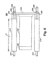
- FIG. 6 illustrates another embodiment of the present invention.
- the fixture 200 may include a strongback 210, a solid block 230 supported at the rear by the strongback 210, and standoffs 215.
- the standoffs 215 have a length L 235 to establish placement for an end face 250 of the solid block 230, when positioned on a slip ring assembly (not shown). Threaded ends 219 screw into receiving points on outer face of outer plate of the slip ring assembly (not shown).
- the end face 250 may include a solid block of metal with cutouts or may include axial-radial arms, both as previously described to avoid interferences at the end of the rotor.
- Upper threads 240 of the standoffs pass through axial holes 245 in the strongback 210.
- threaded bolts 260 will cause end threads 219 to engage receiving points in the outer end plate of the slip ring assembly until the end threads bottom out. Continued operation of the threaded bolts will cause end face 250 of the solid block 230 to engage and push the end of the rotor shaft (not shown) until the slip ring assembly breaks free.
- FIG. 7 illustrates a flowchart for a method of removing a slip ring assembly from the exciter end of a rotating electrical machine using an embodiment of inventive fixture.
- the procedure addresses a slip ring assembly, which may include an electrical connection plate and phase conductor, and a rotor shaft that may include rotor winding cables and an end plate.
Landscapes
- Engineering & Computer Science (AREA)
- Manufacturing & Machinery (AREA)
- Power Engineering (AREA)
- Manufacture Of Motors, Generators (AREA)
- Wind Motors (AREA)
- Motor Or Generator Current Collectors (AREA)
Abstract
Description
- The invention relates generally to rotating electrical machinery and more specifically to slip rings for rotating electrical machinery.
- Slip rings are employed in a wide range of rotating electrical machinery, such as electric motors and electric generators. A typical alternating current (AC) generator, for example, consists of a stationary stator and a rotor mounted within the stator. The stator includes a specific number of coils, each with a specific number of windings. Similarly, the rotor includes of a specific number of field poles, each with a specific number of windings. In addition to the rotor and stator, a generator has a collector assembly, usually including collector slip rings, brushes and brush holders. The rotor contains magnetic fields that are established and fed by an exciter. When the rotor is rotated, AC is induced in the stator. The changing polarity of the rotor, with respect to the stator, produces the alternating characteristics of the current. The generated voltage is proportional to the strength of the magnetic field, the number of stator coils and the number of windings in each coil, and the speed at which the rotor turns. Slip rings are electrical connections that are used to transfer power to and from the rotor of the AC generator. The slip ring may include a circular conducting material connected to the rotor windings and insulated from the rotor shaft. Brushes ride on the slip ring as the rotor rotates. The brush holder maintains the brushes in place, against the slip ring as the rotor rotates. The exciter supplies the DC current to the magnetic field of the rotor through one set of brushes and slip rings and completes a return path from another set of brushes and slip rings.
- A wind turbine generator is a rotating electrical machine that is mechanically coupled to wind turbine blades. The wind turbine generator is positioned in a nacelle at the top of a wind turbine tower. The mechanical energy of the turbine is converted to electrical energy and delivered to a power grid through a collector system. An electronic power converter is used to control the flow of real and reactive power. One common configuration for the wind turbine generator is a doubly fed induction generator with a wound rotor and slip rings. More complex slip ring arrangements are required to convey three-phase ac power to the rotor windings for these types of wind turbine generators.
-
FIG. 1A and FIG. 1B , respectively, illustrate an end view and a side view for an exemplary slip ring assembly for conveying three phase ac power to the rotor of a wind turbine generator. Theslip ring assembly 10 includes an insulatedhub 15 with a cylindricalaxial cavity 20 for receiving an end shaft of the wind turbine generator rotor. Theslip ring assembly 10 includes, relative to the wind turbine generator, anouter end plate 25 and an inner end plate 30 with aground ring 32. Theouter end plate 25 and the inner end plate 30 include a cylindrical axial cavity to accommodate the insulatedhub 15. Theouter end plate 25, inner end plate 30 and insulatedhub 15 are maintained in axial proximity byconnection rods 35 threaded and bolted at the plate ends. Insulatingpieces 40 surround theconnection rods 35 and prevent contact of theconnection rods 35 with the electric power in the slip rings. Three annular conductive contact rings 45 (one for each phase of power to the rotor windings) radially surround and are fixed to theslip ring assembly 10. Thecontact rings 45 provide a contact surface 50 for brushes (not shown) to transfer power to theslip ring assembly 10. Thecontact ring 45 for an individual phase is physically and electrically in contact with one or more conductingrods 55 for that phase. The conductingrods 55 extend outward through theouter end plate 25 and provide for connection to rotor cables (not shown) at the outer end of the rotor shaft (not shown) from the rotor windings (not shown). Insulatingpieces 60 physically separate thecontact rings 45 and isolate the conduction path through theconduction rods 55 for an individual phase of power to the rotor windings. -
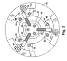
FIG. 2 illustrates electrical connections from the wind turbine generator rotor to the slip ring assembly. Therotor shaft 65 may include a rotorshaft end plate 70. Anelectrical connection plate 75 is mounted to threadedends 80 of the conductingrods 55. Theelectrical connection plate 75 may be constructed of an insulating material to provide for physical connection with the conductingrods 55 for individual rotor phases while providing electrical isolation between the phases. Apower cable 85 for each phase of the rotor windings extends from rotorshaft end plate 70. Thepower cable 85 may be connected to a conductingtab 90 on aphase connecting plate 95 to electrically connect the rotor winding (not shown) through the conductingrods 55 to the associatedcontact ring 45. - As part of the maintenance process of a wind turbine generator, slip ring assemblies are removed and refurbished to renew their operational capability. Removal of the rotor shaft from inside the hub is difficult since the rotor shaft is provided with heat-shrink fit within the hub. Even when the electrical connection plate is removed from the end of the slip ring assembly, there is no physical access available to pry the slip ring assembly from the generator side. Currently, 90% of these assemblies are damaged upon their removal, as a controlled, non-destructive method is not available. Many of the slip rings, which are damaged during removal for refurbishment, are scrapped because they are beyond repair. The slip rings are damaged by an inefficient removal method as a consistent and repeatable approach has not been employed. This results in increased material cost that is magnified by the hundreds of wind turbines in which this issue occurs. The current slip ring removal method involves hitting the assembly with a hammer. Such blows frequently strike the contact surface resulting in surface damage or strike the porcelain insulators, cracking or totally destroying them. While effective in removing the slip ring assembly, the resulting level of damage is unacceptable. This method is unreliable and also increases risk of personal injury.
- Further, difficulty is encountered in removing the slip ring assembly because the wind turbine generator is mounted in the nacelle atop the wind turbine tower, often hundreds of feet above the ground.
- Accordingly, there is a need to provide an apparatus and method for efficiently removing slip rings from the rotors for rotating electrical machinery without damaging the slip ring assembly.
- According to various aspects the present invention relates to a fixture and method for removing a slip ring assembly from the end of rotor shaft of a rotating electrical machine.
- Briefly in accordance with one aspect of the present invention, a fixture is provided, adapted for removing a slip ring assembly for a rotating electrical machine from an outer end of a rotor shaft of the rotating electrical machine. The fixture includes a plurality of standoffs adapted to mount the fixture to the slip ring assembly. A jacking assembly is adapted to apply a disengaging force to an outer end of the rotor shaft for the rotating electrical machine. Further, a strongback is provided, adapted to provide back support for the jacking assembly and for the plurality of standoffs.
- In accordance with another aspect of the present invention, a method is provided for removing a slip ring assembly from an outer end of a rotor shaft of the rotating electrical machine. The slip ring assembly may include an electrical connection plate and phase conductor and the rotor shaft may include rotor winding cables and an end plate.
- The method includes disconnecting electrical connections from the end of the rotor to the slip ring assembly. Interferences are removed. The fixture is first aligned with the slip ring assembly. Then the fixture is attached to the slip ring assembly. The method further includes raising hydraulic pressure on a jacking assembly to release the slip ring assembly from the rotor shaft. When the slip ring assembly is released from the rotor shaft, the fixture is removed from the slip ring assembly.
- Various features, aspects, and advantages of the present invention will become better understood when the following detailed description is read with reference to the accompanying drawings in which like characters represent like parts throughout the drawings, wherein:
-
FIGs. 1A and 1B , respectively, illustrate an end view and a side view of a slip ring assembly for conveying three phase ac power to the rotor of a wind turbine generator; -
FIG. 2 illustrates electrical connections from the wind turbine generator rotor to the slip ring assembly; -
FIGs. 3A, 3B, 3C and 3D , respectively, illustrate a top end view, a side view, a bottom end view and a top view for a first embodiment of the inventive fixture for slip ring assembly removal; -
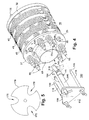
FIG. 4 illustrates the first embodiment of the inventive fixture withcentral axis 150 centered on the end of the rotor shaft of the slip ring assembly; -
FIG. 5 illustrates an alternate embodiment for the end block of the jacking assembly; -
FIG. 6 illustrates another embodiment of the present invention; and -
FIG. 7 illustrates a flowchart for a method of removing a slip ring assembly from the rotor shaft end of a generator using an embodiment of inventive fixture. - The following embodiments of the present invention have many advantages, including providing a lightweight slip ring removal tool that permits removal of a slip ring assembly from rotating electrical machinery without damaging the slip ring, as experienced with previous slip ring removal methods.
- The slip ring removal tool (fixture) may incorporate common, lightweight materials to effectively remove the slip ring assembly. The inventive fixture may allow removal of slip rings from a variety of rotating electrical machinery, including electric motors and electric generators, although the present embodiment of the fixture is adapted for removal of a slip ring assembly from a wind turbine generator.
- This aspect of the present invention greatly minimizes damage incurred during removal, and provides the service engineer with a safe and simple alternative. Mechanical leverage is generated through a jacking assembly to effectively overcome the heat-shrink fit and remove the slip ring with minimal damage and reduced operator effort. The apparatus is mobile enough to be easily lifted by the turbine's winch system, and versatile and lightweight such that a single operator can install, operate, and remove the entire system.
- The slip ring removal fixture provides cost savings in both material and manpower and a process improvement. The fixture significantly reduces the effort and time required for removing the slip rings.
- In one embodiment of the present invention, the apparatus attaches directly to the slip ring assembly through three bolted connection points for ease of installation and removal. A jacking mechanism provides mechanical leverage to pry the slip ring from its heat-shrunk fit mounting location in a manner that is reliable and safe for the service worker and the slip ring assembly. This tool greatly decreases the number of slip rings damaged during this process and allows the vendor to properly refurbish and reuse these critical components.
- The jacking mechanism may include a pneumatic jack, a hydraulic jack or an electric jack. A bottle-type jack, due to its cylindrical and elongated shape, may be advantageous in easily fitting along a central axis of the fixture and aligning with the end of the rotor shaft of the ac generator.
- A second embodiment may eliminate the bottle jack and implement a solid piece of steel tube instead. Then, the nuts may be tightened in succession to slowly remove the slip ring from the generator. This process would be more time consuming, but would eliminate the added expense and weight of the bottle jack.
-
FIGs. 3A, 3B, 3C and 3D illustrate a top end view, a side view, a bottom end view, and a top view for a first embodiment of the slipring removal fixture 100. A jackingassembly 105 is rear mounted to astrongback 110, by convenient means known in the art. Thestrongback 110 may comprise a metal plate, preferably of strong, but lightweight metal, such as but not limited to aluminum.Standoffs 115 are also rear mounted to thestrongback 110. Thestandoffs 115 may also include a strong, but lightweight, metal tubing such as but not limited to aluminum. Other materials such as steel may be preferred. Thestandoffs 115 may include means for fastening the fixture to corresponding receiving points 120 on theouter face 27 of theouter end plate 25 of the slip ring assembly. The means may include threaded ends 119 adapted to mate with threaded boltholes on theouter face 27 of theouter end plate 25. Thestandoffs 115 and the corresponding receiving points 120 may be symmetrically and circumferentially spaced around theouter face 27 of theouter end plate 25. Alength 117 of thestandoff 115 establishes a distance between thestrongback 110 and theouter end plate 25 of theslip ring assembly 10. - The jacking
assembly 105 is adapted to apply a disengaging force to an outer end of the rotor shaft for a wind turbine generator. The jackingassembly 105 includes ajack 140, which may include a hydraulic jack, a pneumatic jack, or an electric powered jack. Thejack 140 may be a bottle jack, which is relatively light and where the bottle-shape is particularly shaped to be placed along the center of the fixture. A lightweight and compact fixture is especially desirable for removing the slip ring assembly from the rotor shaft on a wind turbine generator. - An
operating piston 145 of thejack 140 may be centered along acentral axis 150 of thefixture 100. Anoutside pressure source 155, conveniently located in proximity to thejack 140 may provide pressure toconnection 157 to thejack 140. When pressure is applied to thejack 140, theoperating piston 145 moves along thecentral axis 150 in a direction away from thestrongback 110. - The jacking
assembly 105 may also include: anend block 160 situated at an outer end of theoperating piston 145. Theend block 160 is adapted to engage the outer end of therotor shaft 65 of the wind turbine generator. Thelength 117 of thestandoffs 115 may also result in positioning theend block 160 in close proximity to the outer end of the rotor, when the fixture is mounted on theslip ring assembly 10, such that the stroke of theoperating piston 145 will engage and provide sufficient force against the outer end of the rotor shaft 165 to cause a release of theslip ring assembly 10. - The
end block 160 may comprise a body, mechanically attached to an outer end 147 of theoperating piston 145 by means known in the art. Theend block 160 may also include a plurality ofarms 170 extending radially and axially from thecentral axis 150 of thefixture 100 configured withcutouts 180 providing a radial-circumferential space between each of the plurality ofarms 170. Thecutouts 180 may be sized to avoid interference with a plurality ofrotor windings cables 85 extending from an end surface of the outer end of therotor shaft 65 of the rotating electrical machine. - The
fixture 100 may further include a threadedupper stem 185 on thestandoffs 115, passing through threadedaxial holes 190 in thestrongback 110.Tee operators 195 or other suitable devices may be mounted to theupper stem 185 to facilitate threading of thestandoffs 115 onto the corresponding receiving points 120 of the slip ring assembly. -
FIG. 4 illustrates thefixture 100 lined up for mounting onto theslip ring assembly 10 of a rotatingelectrical machine 5. Thecentral axis 150 of thefixture 100 is centered on the end of therotor shaft 65 of theslip ring assembly 10. Threaded ends 119 ofstandoffs 115 are also lined up with threaded receiving points 120 on theouter face 27 ofouter end plate 25 of theslip ring assembly 10.End block 160 is lined up to apply force fromjack 140 to therotor shaft 65 of theslip ring assembly 10 of the rotating electrical machine. -
FIG. 5 illustrates an alternate embodiment for the end block of the jacking assembly. Theend block 160 may include a plate-shapedend block 170 to engage the outer end of therotor shaft 65 of the wind turbine generator. The plate-shapedend block 170 may be provided with a plurality ofradial cutouts 175 to avoid interference with a plurality ofrotor windings cables 85 extending from an end surface of the outer end of therotor shaft 65 of a wind turbine generator. -
FIG. 6 illustrates another embodiment of the present invention. Thefixture 200 may include astrongback 210, asolid block 230 supported at the rear by thestrongback 210, andstandoffs 215. Thestandoffs 215 have a length L 235 to establish placement for anend face 250 of thesolid block 230, when positioned on a slip ring assembly (not shown). Threaded ends 219 screw into receiving points on outer face of outer plate of the slip ring assembly (not shown). Theend face 250 may include a solid block of metal with cutouts or may include axial-radial arms, both as previously described to avoid interferences at the end of the rotor.Upper threads 240 of the standoffs pass throughaxial holes 245 in thestrongback 210. Operation of threadedbolts 260 will cause endthreads 219 to engage receiving points in the outer end plate of the slip ring assembly until the end threads bottom out. Continued operation of the threaded bolts will causeend face 250 of thesolid block 230 to engage and push the end of the rotor shaft (not shown) until the slip ring assembly breaks free. -
FIG. 7 illustrates a flowchart for a method of removing a slip ring assembly from the exciter end of a rotating electrical machine using an embodiment of inventive fixture. The procedure addresses a slip ring assembly, which may include an electrical connection plate and phase conductor, and a rotor shaft that may include rotor winding cables and an end plate. - In
step 310, electrical connections to the slip ring assembly are disconnected. Disconnection may include disconnecting the rotor winding cabling from an electrical connection plate of a slip ring assembly, in preparation for removing an electrical connection plate for the rotor winding cable. However, the disconnection step may also include disconnecting any electrical connections to the slip ring assembly, that are required for removal of the slip ring assembly from the shaft for the specific piece of rotating electrical machinery. Instep 320, various interferences at the end of the slip ring assembly may be removed. Such inteferences comprise any structures or components at the end of slip ring assembly or rotor shaft that may prevent or hinder mounting or operation of the fixture, and may include the electrical connection plate, for example. The electrical connection plate may require unbolting from the conduction rod ends on the slip ring assembly. Instep 330, the fixture is aligned with the slip ring assembly. The alignment step may include positioning the ends of the standoffs in proximity to receiving points on the outer end plate of the slip ring assembly. In one embodiment of the inventive fixture, the receiving points on the outer face of outer end plate may include threaded boltholes for receiving threads at the end of the associated standoffs. In step 340, the fixture is attached to the slip ring assembly. Attaching may include threading ends of a plurality of standoffs into the corresponding threaded holes in an end plate of the slip ring assembly. - Hydraulic pressure is raised on the jacking assembly in
step 350 to release the slip ring assembly from the rotor shaft. A predetermined limit may be set on the pressure applied to the jacking assembly in order to limit forces and preclude damage to the slip ring assembly and the fixture, as well as to ensure personnel safety. Instep 360, the fixture is removed from the released slip ring assembly. - While various embodiments are described herein, it will be appreciated from the specification that various combinations of elements, variations or improvements therein may be made, and are within the scope of the invention.
- Various aspects and embodiments of the present invention are now defined by the following numbered clauses:
- 1. A fixture adapted for removing a slip ring assembly for a rotating electrical machine from an outer end of a rotor shaft of the ac rotating electrical machine; comprising:
- a plurality of standoffs adapted to mount the fixture to slip ring assembly;
- a jacking assembly adapted to apply a disengaging force to an outer end of the rotor shaft; and
- a strongback adapted to provide back support for the jacking assembly and for the standoffs.
- 2. The fixture adapted for removing a slip ring assembly according to
clause 1, wherein the plurality of standoffs fixedly engage the outer end plate of the slip ring assembly and fixedly engage the strongback to maintain a predetermined separation between the strongback and the outer end plate of the slip ring assembly. - 3. The fixture adapted for removing a slip ring assembly according to any preceding clause, wherein the plurality of standoffs are symetrically distributed circumferentially between the strongback and the outer end plate of the slip ring assembly.
- 4. The fixture adapted for removing a slip ring assembly according to any preceding clause, wherein the plurality of standoffs include end threads to engage corresponding threaded holes on an outer face of the outer end plate of the slip ring assembly.
- 5. The fixture adapted for removing a slip ring assembly according to any preceding clause, wherein the strongback includes a plurality of threaded axial holes to engage a corresponding plurality of threaded axial sections of the standoffs and wherein the standoffs include turning means to facilitate threading the threaded end into the outer face of the end plate of the slip ring assembly.
- 6. The jacking assembly adapted to apply a disengaging force to an outer end of the rotor shaft for a rotating electrical machine according to any preceding clause, comprising:
- at least one of a hydraulic jack, a pneumatic jack, and an electric powered jack wherein an operating piston of the jack is centered along a central axis of the fixture and wherein the piston moves along the central axis in a direction away from the strongback.
- 7. The jacking assembly according to any preceding clause, wherein the jacking assembly comprises: a bottle jack.
- 8. The jacking assembly according to any preceding clause, further comprising:
- an end block at an outer end of the piston, wherein the end block is adapted to engage the outer end of the rotor shaft of the rotating electrical machine.
- 9. The jacking assembly according to any preceding clause, the end block comprising: a plate shaped to engage the outer end of the rotor shaft of the rotating electrical machine, including a plurality of cutouts to avoid interference with a plurality of rotor windings cables extending from an end surface of the outer end of the rotor shaft of the rotating electrical machine.
- 10. The jacking assembly according to any preceding clause, the end block comprising:
- a body; and
- a plurality of arms extending radially and axially from the central axis of the fixture configured with a radial space between the plurality of arms to avoid interference with a plurality of rotor windings cables extending from an end surface of the outer end of the rotor shaft of the rotating electrical machine.
- 11. The fixture adapted for removing a slip ring assembly for a rotating electrical machine from an outer end of a rotor shaft of the rotating electrical machine according to any preceding clause, wherein the rotating electrical machine comprises a wind turbine generator.
- 12. A method for removing a slip ring assembly for a rotating electrical machine from an outer end of a rotor shaft of the rotating electrical machine, wherein outer end of the rotor includes electrical connections to the slip ring assembly, the method comprising:
- disconnecting the rotor electrical connections from a slip ring assembly;
- removing interferences;
- positioning the fixture on the slip ring assembly;
- attaching the fixture to the slip ring assembly;
- raising hydraulic pressure on a jacking assembly to release the slip ring assembly from the rotor shaft; and
- removing the fixture from the slip ring assembly.
- 13. The method for removing a slip ring assembly according to clause 12, the step of removing interferences comprising: unbolting an electrical connection plate from phase conductors of the slip ring assembly.
- 14. The method for removing a slip ring assembly according to clause 12 or 13, the step of positioning the fixture on the slip ring assembly comprising:
- locating an outer end of a block of a jacking assembly in proximity with an outer end of the rotor shaft wherein cutouts of the block are positioned at the location of cable interferences; and
- aligning ends of a plurality of standoffs in proximity to receiving areas on an outer surface of an end plate of the slip ring assembly.
- 15. The method for removing a slip ring assembly according to any of clauses 12 to 14, the step of attaching the fixture comprising: threading ends of a plurality of standoffs into the corresponding threaded holes in an end plate of the slip ring assembly.
- 16. The method for removing a slip ring assembly according to any of clauses 12 to 15, the step of raising pressure comprising:
- raising hydraulic pressure till the end block engages the end surface of the rotor shaft.
- 17. The method for removing a slip ring assembly according to any of clauses 12 to 16, the step of raising hydraulic pressure further comprising:
- raising hydraulic pressure within predetermined limits to cause the slip ring assembly to release from the rotor shaft.
- 18. A fixture adapted for removing a slip ring assembly for a rotating electrical machine from an outer end of a rotor shaft of the rotating electrical machine; comprising:
- a plurality of standoffs adapted to mount the fixture to slip ring assembly, wherein the plurality of standoffs fixedly engage the outer end plate of the slip ring assembly with a thread lower end and the plurality of standoffs further include a threaded upper end;
- a solid block oriented along a centerline of the fixture, adapted to engage the outer end of the rotor shaft of the rotating electrical machine;
- a strongback adapted to provide back support for the solid block and for the standoffs, wherein the strongback includes a plurality of axial holes located to receive and pass the threaded upper ends of the plurality of standoffs; and
- threaded bolts positioned on the threaded upper end of the plurality of standoffs, adapted to force the strongback and the solid block toward the slip ring assembly.
- 19. The fixture adapted for removing a slip ring assembly according to clause 18, the solid block further comprising: an end face wherein the end face includes a solid plate with a plurality of cutouts disposed to avoid contact with interferences on the end of the rotor shaft of the rotating electrical machine.
- 20. The fixture adapted for removing a slip ring assembly according to clause 18 or 19, the solid block further comprising: an end face wherein the end face includes a plurality of axial and radial arms separated by a plurality of cutouts disposed to avoid contact with interferences on the end of the rotor shaft of the rotating electrical machine.
Claims (10)
- A fixture (100) adapted for removing a slip ring assembly (10) for a rotating electrical machine (5) from an outer end (70) of a rotor shaft (65) of the ac rotating electrical machine (5); comprising:a plurality of standoffs (115) adapted to mount the fixture (100) to the slip ring assembly (10);a jacking assembly (105) adapted to apply a disengaging force to an outer end (70) of the rotor shaft (65); anda strongback (110) adapted to provide back support for the jacking assembly and for the standoffs (115).
- The fixture (100) adapted for removing a slip ring assembly (10) according to Claim 1, wherein the plurality of standoffs (115) fixedly engage the outer end plate (25) of the slip ring assembly (10) and fixedly engage the strongback (110) to maintain a predetermined separation between the strongback (110) and the outer end plate (25) of the slip ring assembly (10).
- The fixture (100) adapted for removing a slip ring assembly (10) according to any preceding Claim, wherein the plurality of standoffs (115) are symetrically distributed circumferentially between the strongback (110) and the outer end plate (25) of the slip ring assembly (10) and wherein the plurality of standoffs (115) include end threads (119) to engage corresponding threaded holes (125) on an outer face (27) of the outer end plate (25) of the slip ring assembly (10).
- The fixture (100) adapted for removing a slip ring assembly (10) according to any preceding Claim, wherein the strongback (110) includes a plurality of threaded axial holes (190) to engage a corresponding plurality of threaded axial sections (185) of the standoffs (115) and wherein the standoffs (115) include turning means (195) to facilitate threading the threaded end (119) into the outer face (27) of the end plate (25) of the slip ring assembly (10).
- The fixture (100) according to any preceding claim, adapted for removing a slip ring assembly (10) for a rotating electrical machine (5); wherein the rotating electrical machine (5) comprises a wind turbine generator.
- A jacking assembly (105) adapted to apply a disengaging force to an outer end (70) of the rotor shaft (65) for a rotating electrical machine (5) comprising:at least one of a hydraulic jack, a pneumatic jack, and an electric powered jack wherein an operating piston (145) is centered along a central axis (150) of the fixture (100) and wherein the piston moves along the central axis (150) in a direction away from the strongback (110).
- The jacking assembly (145) according to Claim 6, further comprising a bottle jack.
- The jacking assembly (105) according to Claim 6 or Claim 7, further comprising: an end block (160) at an outer end of the operating piston (145), wherein the end block (160) is adapted to engage the outer end (70) of the rotor shaft (65) of the rotating electrical machine (5), and wherein the end block (160) includes a plurality of cutouts to avoid interference with electrical connections (85) extending from an end surface of the outer end (70) of the rotor shaft (65) of the rotating electrical machine (5).
- The jacking assembly (145) according to any of Claims 6 to 8, the end block (160) comprising:a body; anda plurality of arms (170) extending radially and axially from the central axis (150) of the fixture (100) configured with a radial space between the plurality of arms (170) to avoid interference with a plurality of rotor windings cables (85) extending from the outer end (70) of the rotor shaft (65) of the rotating electrical machine (5).
- A method for removing a slip ring assembly (10) for a rotating electrical machine (5) from an outer end (70) of a rotor shaft (65) of the rotating electrical machine (5), wherein outer end (70) of the rotor shaft (65) includes electrical connections (85) to the slip ring assembly (10), the method comprising:disconnecting the rotor electrical connections (85) from a slip ring assembly (10);removing interferences (75);positioning a fixture (100) on the slip ring assembly (10);attaching the fixture (100) to the slip ring assembly (10);raising hydraulic pressure on a jacking assembly (145) to release the slip ring assembly (10) from the rotor shaft (65); andremoving the fixture (100) from the slip ring assembly (10).
Applications Claiming Priority (1)
| Application Number | Priority Date | Filing Date | Title |
|---|---|---|---|
| US12/164,166 US8528192B2 (en) | 2008-06-30 | 2008-06-30 | Fixture for removing slip rings from rotating electrical machinery |
Publications (3)
| Publication Number | Publication Date |
|---|---|
| EP2141787A2 true EP2141787A2 (en) | 2010-01-06 |
| EP2141787A3 EP2141787A3 (en) | 2017-02-15 |
| EP2141787B1 EP2141787B1 (en) | 2020-05-27 |
Family
ID=41138893
Family Applications (1)
| Application Number | Title | Priority Date | Filing Date |
|---|---|---|---|
| EP09163146.5A Active EP2141787B1 (en) | 2008-06-30 | 2009-06-18 | Apparatus and method for removing slip rings from rotating electrical machinery |
Country Status (6)
| Country | Link |
|---|---|
| US (1) | US8528192B2 (en) |
| EP (1) | EP2141787B1 (en) |
| CN (1) | CN101621231B (en) |
| CA (1) | CA2670192C (en) |
| DK (1) | DK2141787T3 (en) |
| ES (1) | ES2809235T3 (en) |
Cited By (2)
| Publication number | Priority date | Publication date | Assignee | Title |
|---|---|---|---|---|
| CN107147254A (en) * | 2017-07-06 | 2017-09-08 | 柳州杰诺瑞汽车电器系统制造有限公司 | Generator positive plate pressure B+ bolts, insulation sleeve integrated device and method of work |
| CN107553387A (en) * | 2017-08-28 | 2018-01-09 | 安徽江淮汽车集团股份有限公司 | A kind of gearbox provision for disengagement |
Families Citing this family (18)
| Publication number | Priority date | Publication date | Assignee | Title |
|---|---|---|---|---|
| US8618943B2 (en) | 2007-05-24 | 2013-12-31 | Cutsforth, Inc. | Brush holder assembly monitoring apparatus, assembly, system and method |
| US10009582B2 (en) * | 2009-02-13 | 2018-06-26 | Seesoon, Inc. | Pipe inspection system with replaceable cable storage drum |
| EP2545275B1 (en) * | 2010-03-10 | 2016-08-17 | SSB Wind Systems GmbH & Co. KG | Redundant pitch system |
| CN102013764B (en) * | 2010-11-19 | 2013-03-20 | 永济新时速电机电器有限责任公司 | Device for changing slip ring of motor |
| US8558429B2 (en) | 2011-01-05 | 2013-10-15 | General Electric Company | Systems, methods, and apparatus for lifting brushes of an induction motor |
| US8674581B2 (en) | 2011-01-05 | 2014-03-18 | General Electric Company | Systems, methods, and apparatus for shorting slip rings of an induction motor |
| JP5146583B1 (en) * | 2011-10-28 | 2013-02-20 | 三菱マテリアル株式会社 | Rotor separator |
| US9735530B2 (en) * | 2015-03-10 | 2017-08-15 | General Electric Company | Apparatus and method for axially spacing conductive rings of a slip ring assembly |
| US9866035B2 (en) | 2015-03-27 | 2018-01-09 | Irobot Corporation | Rotatable coupling |
| EP3082202A1 (en) * | 2015-04-17 | 2016-10-19 | Siemens Aktiengesellschaft | Slip ring body comprising a rotor for an electrically excited rotational dynamo-electric machine |
| US10088167B2 (en) | 2015-06-15 | 2018-10-02 | General Electric Company | Combustion flow sleeve lifting tool |
| CN107742958B (en) * | 2017-11-28 | 2024-06-21 | 国网冀北张家口风光储输新能源有限公司 | A equipment for aerogenerator sliding ring dismantles |
| DE102019114029A1 (en) * | 2019-05-24 | 2020-11-26 | Lufthansa Technik Aktiengesellschaft | Tool for holding the high pressure shaft of an aircraft engine |
| CN111774352B (en) * | 2020-07-07 | 2023-10-31 | 湖北清江水电开发有限责任公司 | Automatic cleaning device and cleaning method for stator bar iron core of hydraulic generator |
| CN112271522A (en) * | 2020-11-09 | 2021-01-26 | 苏州港联机电有限公司 | Electricity-taking slip ring of wind driven generator |
| DE102023203195A1 (en) * | 2023-04-06 | 2024-10-10 | Zf Friedrichshafen Ag | Device and method for non-destructive disassembly of a stator |
| CN117559738B (en) * | 2024-01-09 | 2024-03-12 | 深圳市品成电机有限公司 | Motor rotor processing equipment |
| WO2025149557A1 (en) * | 2024-01-12 | 2025-07-17 | Morgan Advanced Materials Plc | Wind generator |
Family Cites Families (21)
| Publication number | Priority date | Publication date | Assignee | Title |
|---|---|---|---|---|
| US1513031A (en) * | 1922-02-21 | 1924-10-28 | Oliver M Brown | Device for removing and replacing engine cam shafts and bushings |
| US4195398A (en) * | 1977-12-12 | 1980-04-01 | Matthews Robert L | Pulling tool |
| US4594771A (en) * | 1984-09-20 | 1986-06-17 | Machine Products Corporation | Apparatus and method for automatically inserting coils and wedges into a stator core of any given length |
| US4799309A (en) * | 1987-12-24 | 1989-01-24 | Ford Motor Company | Method of making a rectifier and control module for an alternator |
| CN1006671B (en) * | 1988-04-23 | 1990-01-31 | 辽宁省能源研究所 | Winding type asynchronous motor and its manufacturing method |
| US5650679A (en) * | 1993-03-18 | 1997-07-22 | Boggs, Iii; Paul Dewey | Eddy current drive |
| US5587616A (en) * | 1993-05-04 | 1996-12-24 | Sundstrand Corporation | Rotor for a dynamoelectric machine having a one-piece rotation rectifier |
| EP0862806A4 (en) * | 1996-07-30 | 1999-04-14 | Fifth Dimension Inc | Brushless slip ring using rolling elements as electrical conductors |
| US6012711A (en) * | 1997-12-10 | 2000-01-11 | International Business Machines Corporation | Alignment device for establishing a coplanar relationship between first and second surfaces |
| DE10003900B4 (en) * | 2000-01-29 | 2004-02-19 | Schunk Metall Und Kunststoff Gmbh | Current-transfer assembly |
| JP3445953B2 (en) * | 2000-02-24 | 2003-09-16 | ファナック株式会社 | Coil inserter for stator winding |
| JP3932177B2 (en) * | 2002-05-24 | 2007-06-20 | 株式会社ジェイテクト | Motor manufacturing equipment |
| CN2558151Y (en) * | 2002-07-18 | 2003-06-25 | 徐凤鸣 | Energy saving motor |
| US20040169434A1 (en) * | 2003-01-02 | 2004-09-02 | Washington Richard G. | Slip ring apparatus |
| WO2004113015A2 (en) * | 2003-06-20 | 2004-12-29 | Par Systems, Inc. | Flexible fixture |
| US7415758B2 (en) * | 2003-09-10 | 2008-08-26 | Minebea Co., Ltd. | Device to press the shaft of a rotor into a stator housing |
| US7075192B2 (en) * | 2004-04-19 | 2006-07-11 | Northern Power Systems, Inc. | Direct drive wind turbine |
| US8387258B2 (en) * | 2004-05-07 | 2013-03-05 | Teco-Westinghouse Motor Company | Insulated bearing assemblies |
| CH697889B1 (en) * | 2004-05-07 | 2009-03-13 | Etel Sa | Method and device for positioning and fixing the magnet on a magnetic yoke of a motor. |
| CN101075767A (en) * | 2007-04-12 | 2007-11-21 | 中国北车集团永济电机厂 | Asynchronous electric motor with stator and rotor rotation simultaneously |
| US8713776B2 (en) * | 2010-04-07 | 2014-05-06 | General Electric Company | System and tool for installing combustion liners |
-
2008
- 2008-06-30 US US12/164,166 patent/US8528192B2/en active Active
-
2009
- 2009-06-18 ES ES09163146T patent/ES2809235T3/en active Active
- 2009-06-18 EP EP09163146.5A patent/EP2141787B1/en active Active
- 2009-06-18 DK DK09163146.5T patent/DK2141787T3/en active
- 2009-06-25 CA CA2670192A patent/CA2670192C/en active Active
- 2009-06-30 CN CN200910159428.XA patent/CN101621231B/en active Active
Cited By (4)
| Publication number | Priority date | Publication date | Assignee | Title |
|---|---|---|---|---|
| CN107147254A (en) * | 2017-07-06 | 2017-09-08 | 柳州杰诺瑞汽车电器系统制造有限公司 | Generator positive plate pressure B+ bolts, insulation sleeve integrated device and method of work |
| CN107147254B (en) * | 2017-07-06 | 2023-09-01 | 柳州杰诺瑞汽车电器系统制造有限公司 | Generator positive plate B+ bolt and insulating sleeve integrated device and working method thereof |
| CN107553387A (en) * | 2017-08-28 | 2018-01-09 | 安徽江淮汽车集团股份有限公司 | A kind of gearbox provision for disengagement |
| CN107553387B (en) * | 2017-08-28 | 2019-06-28 | 安徽江淮汽车集团股份有限公司 | A kind of gearbox provision for disengagement |
Also Published As
| Publication number | Publication date |
|---|---|
| CN101621231B (en) | 2014-03-05 |
| CA2670192A1 (en) | 2009-12-30 |
| CN101621231A (en) | 2010-01-06 |
| US8528192B2 (en) | 2013-09-10 |
| CA2670192C (en) | 2014-08-12 |
| DK2141787T3 (en) | 2020-08-31 |
| EP2141787A3 (en) | 2017-02-15 |
| US20090320279A1 (en) | 2009-12-31 |
| EP2141787B1 (en) | 2020-05-27 |
| ES2809235T3 (en) | 2021-03-03 |
Similar Documents
| Publication | Publication Date | Title |
|---|---|---|
| EP2141787B1 (en) | Apparatus and method for removing slip rings from rotating electrical machinery | |
| US9181927B2 (en) | Lightning protection system for a wind turbine, wind turbine and method for protecting components of a wind turbine against lightning strikes | |
| KR101234378B1 (en) | Wind turbine generator and maintenance method thereof | |
| US10886811B2 (en) | Segmented stator assembly with flexible electrical connections, generator and wind turbine with such a stator assembly | |
| US9190890B2 (en) | Method and apparatus for removal and replacement of a wound stator core | |
| EP2680413A2 (en) | Method and apparatus for removing a coil from a slot of a dynamoelectric machine | |
| CN207542954U (en) | Part replacement tool and the wind turbine for power generation | |
| CN111386651B (en) | Stator assemblies, generators and wind turbines | |
| CN106464061A (en) | A method for repairing an electric generator | |
| CN108980114B (en) | A special stator for wind turbine dynamic balance correction and implementation method | |
| US10236741B2 (en) | Method and test tool for adjusting brush holders in slip ring systems | |
| CN112600330A (en) | Bus bar device for wind turbine generator | |
| US7245030B2 (en) | Integrated generator and transformer and associated methods | |
| KR200448933Y1 (en) | Vertical Motor Rotor Take-In Device | |
| CN203491858U (en) | Mounting/dismounting tool for motor bearing | |
| CN219592193U (en) | Insulating end cover of motor | |
| CN212374584U (en) | Large-scale motor enameled wire winding auxiliary device | |
| CN110235011A (en) | For carrying out the method and electric generator inspection system that failure determines at generator | |
| WO2024019737A1 (en) | Fiber reinforced composite armature winding support structure for a superconducting machine | |
| CN115458249A (en) | Novel connecting structure of coil and composite insulator | |
| CN115483801A (en) | Replacement tool and method for active stator parts |
Legal Events
| Date | Code | Title | Description |
|---|---|---|---|
| PUAI | Public reference made under article 153(3) epc to a published international application that has entered the european phase |
Free format text: ORIGINAL CODE: 0009012 |
|
| AK | Designated contracting states |
Kind code of ref document: A2 Designated state(s): AT BE BG CH CY CZ DE DK EE ES FI FR GB GR HR HU IE IS IT LI LT LU LV MC MK MT NL NO PL PT RO SE SI SK TR |
|
| PUAL | Search report despatched |
Free format text: ORIGINAL CODE: 0009013 |
|
| AK | Designated contracting states |
Kind code of ref document: A3 Designated state(s): AT BE BG CH CY CZ DE DK EE ES FI FR GB GR HR HU IE IS IT LI LT LU LV MC MK MT NL NO PL PT RO SE SI SK TR |
|
| AX | Request for extension of the european patent |
Extension state: AL BA RS |
|
| RIC1 | Information provided on ipc code assigned before grant |
Ipc: H02K 15/00 20060101AFI20170110BHEP |
|
| STAA | Information on the status of an ep patent application or granted ep patent |
Free format text: STATUS: REQUEST FOR EXAMINATION WAS MADE |
|
| 17P | Request for examination filed |
Effective date: 20170816 |
|
| RBV | Designated contracting states (corrected) |
Designated state(s): AT BE BG CH CY CZ DE DK EE ES FI FR GB GR HR HU IE IS IT LI LT LU LV MC MK MT NL NO PL PT RO SE SI SK TR |
|
| STAA | Information on the status of an ep patent application or granted ep patent |
Free format text: STATUS: EXAMINATION IS IN PROGRESS |
|
| 17Q | First examination report despatched |
Effective date: 20180420 |
|
| GRAP | Despatch of communication of intention to grant a patent |
Free format text: ORIGINAL CODE: EPIDOSNIGR1 |
|
| STAA | Information on the status of an ep patent application or granted ep patent |
Free format text: STATUS: GRANT OF PATENT IS INTENDED |
|
| INTG | Intention to grant announced |
Effective date: 20191217 |
|
| GRAS | Grant fee paid |
Free format text: ORIGINAL CODE: EPIDOSNIGR3 |
|
| GRAA | (expected) grant |
Free format text: ORIGINAL CODE: 0009210 |
|
| STAA | Information on the status of an ep patent application or granted ep patent |
Free format text: STATUS: THE PATENT HAS BEEN GRANTED |
|
| AK | Designated contracting states |
Kind code of ref document: B1 Designated state(s): AT BE BG CH CY CZ DE DK EE ES FI FR GB GR HR HU IE IS IT LI LT LU LV MC MK MT NL NO PL PT RO SE SI SK TR |
|
| REG | Reference to a national code |
Ref country code: GB Ref legal event code: FG4D |
|
| REG | Reference to a national code |
Ref country code: CH Ref legal event code: EP |
|
| REG | Reference to a national code |
Ref country code: AT Ref legal event code: REF Ref document number: 1275594 Country of ref document: AT Kind code of ref document: T Effective date: 20200615 |
|
| REG | Reference to a national code |
Ref country code: DE Ref legal event code: R096 Ref document number: 602009062109 Country of ref document: DE |
|
| REG | Reference to a national code |
Ref country code: DK Ref legal event code: T3 Effective date: 20200826 |
|
| REG | Reference to a national code |
Ref country code: LT Ref legal event code: MG4D |
|
| PG25 | Lapsed in a contracting state [announced via postgrant information from national office to epo] |
Ref country code: PT Free format text: LAPSE BECAUSE OF FAILURE TO SUBMIT A TRANSLATION OF THE DESCRIPTION OR TO PAY THE FEE WITHIN THE PRESCRIBED TIME-LIMIT Effective date: 20200928 Ref country code: GR Free format text: LAPSE BECAUSE OF FAILURE TO SUBMIT A TRANSLATION OF THE DESCRIPTION OR TO PAY THE FEE WITHIN THE PRESCRIBED TIME-LIMIT Effective date: 20200828 Ref country code: NO Free format text: LAPSE BECAUSE OF FAILURE TO SUBMIT A TRANSLATION OF THE DESCRIPTION OR TO PAY THE FEE WITHIN THE PRESCRIBED TIME-LIMIT Effective date: 20200827 Ref country code: LT Free format text: LAPSE BECAUSE OF FAILURE TO SUBMIT A TRANSLATION OF THE DESCRIPTION OR TO PAY THE FEE WITHIN THE PRESCRIBED TIME-LIMIT Effective date: 20200527 Ref country code: FI Free format text: LAPSE BECAUSE OF FAILURE TO SUBMIT A TRANSLATION OF THE DESCRIPTION OR TO PAY THE FEE WITHIN THE PRESCRIBED TIME-LIMIT Effective date: 20200527 Ref country code: SE Free format text: LAPSE BECAUSE OF FAILURE TO SUBMIT A TRANSLATION OF THE DESCRIPTION OR TO PAY THE FEE WITHIN THE PRESCRIBED TIME-LIMIT Effective date: 20200527 Ref country code: IS Free format text: LAPSE BECAUSE OF FAILURE TO SUBMIT A TRANSLATION OF THE DESCRIPTION OR TO PAY THE FEE WITHIN THE PRESCRIBED TIME-LIMIT Effective date: 20200927 |
|
| REG | Reference to a national code |
Ref country code: NL Ref legal event code: MP Effective date: 20200527 |
|
| PG25 | Lapsed in a contracting state [announced via postgrant information from national office to epo] |
Ref country code: BG Free format text: LAPSE BECAUSE OF FAILURE TO SUBMIT A TRANSLATION OF THE DESCRIPTION OR TO PAY THE FEE WITHIN THE PRESCRIBED TIME-LIMIT Effective date: 20200827 Ref country code: LV Free format text: LAPSE BECAUSE OF FAILURE TO SUBMIT A TRANSLATION OF THE DESCRIPTION OR TO PAY THE FEE WITHIN THE PRESCRIBED TIME-LIMIT Effective date: 20200527 Ref country code: HR Free format text: LAPSE BECAUSE OF FAILURE TO SUBMIT A TRANSLATION OF THE DESCRIPTION OR TO PAY THE FEE WITHIN THE PRESCRIBED TIME-LIMIT Effective date: 20200527 |
|
| REG | Reference to a national code |
Ref country code: AT Ref legal event code: MK05 Ref document number: 1275594 Country of ref document: AT Kind code of ref document: T Effective date: 20200527 |
|
| PG25 | Lapsed in a contracting state [announced via postgrant information from national office to epo] |
Ref country code: NL Free format text: LAPSE BECAUSE OF FAILURE TO SUBMIT A TRANSLATION OF THE DESCRIPTION OR TO PAY THE FEE WITHIN THE PRESCRIBED TIME-LIMIT Effective date: 20200527 |
|
| PG25 | Lapsed in a contracting state [announced via postgrant information from national office to epo] |
Ref country code: AT Free format text: LAPSE BECAUSE OF FAILURE TO SUBMIT A TRANSLATION OF THE DESCRIPTION OR TO PAY THE FEE WITHIN THE PRESCRIBED TIME-LIMIT Effective date: 20200527 Ref country code: IT Free format text: LAPSE BECAUSE OF FAILURE TO SUBMIT A TRANSLATION OF THE DESCRIPTION OR TO PAY THE FEE WITHIN THE PRESCRIBED TIME-LIMIT Effective date: 20200527 Ref country code: CZ Free format text: LAPSE BECAUSE OF FAILURE TO SUBMIT A TRANSLATION OF THE DESCRIPTION OR TO PAY THE FEE WITHIN THE PRESCRIBED TIME-LIMIT Effective date: 20200527 Ref country code: RO Free format text: LAPSE BECAUSE OF FAILURE TO SUBMIT A TRANSLATION OF THE DESCRIPTION OR TO PAY THE FEE WITHIN THE PRESCRIBED TIME-LIMIT Effective date: 20200527 Ref country code: EE Free format text: LAPSE BECAUSE OF FAILURE TO SUBMIT A TRANSLATION OF THE DESCRIPTION OR TO PAY THE FEE WITHIN THE PRESCRIBED TIME-LIMIT Effective date: 20200527 |
|
| REG | Reference to a national code |
Ref country code: CH Ref legal event code: PL |
|
| PG25 | Lapsed in a contracting state [announced via postgrant information from national office to epo] |
Ref country code: PL Free format text: LAPSE BECAUSE OF FAILURE TO SUBMIT A TRANSLATION OF THE DESCRIPTION OR TO PAY THE FEE WITHIN THE PRESCRIBED TIME-LIMIT Effective date: 20200527 Ref country code: SK Free format text: LAPSE BECAUSE OF FAILURE TO SUBMIT A TRANSLATION OF THE DESCRIPTION OR TO PAY THE FEE WITHIN THE PRESCRIBED TIME-LIMIT Effective date: 20200527 Ref country code: MC Free format text: LAPSE BECAUSE OF FAILURE TO SUBMIT A TRANSLATION OF THE DESCRIPTION OR TO PAY THE FEE WITHIN THE PRESCRIBED TIME-LIMIT Effective date: 20200527 |
|
| REG | Reference to a national code |
Ref country code: DE Ref legal event code: R097 Ref document number: 602009062109 Country of ref document: DE |
|
| REG | Reference to a national code |
Ref country code: ES Ref legal event code: FG2A Ref document number: 2809235 Country of ref document: ES Kind code of ref document: T3 Effective date: 20210303 |
|
| PG25 | Lapsed in a contracting state [announced via postgrant information from national office to epo] |
Ref country code: LU Free format text: LAPSE BECAUSE OF NON-PAYMENT OF DUE FEES Effective date: 20200618 |
|
| PLBE | No opposition filed within time limit |
Free format text: ORIGINAL CODE: 0009261 |
|
| STAA | Information on the status of an ep patent application or granted ep patent |
Free format text: STATUS: NO OPPOSITION FILED WITHIN TIME LIMIT |
|
| REG | Reference to a national code |
Ref country code: BE Ref legal event code: MM Effective date: 20200630 |
|
| GBPC | Gb: european patent ceased through non-payment of renewal fee |
Effective date: 20200827 |
|
| PG25 | Lapsed in a contracting state [announced via postgrant information from national office to epo] |
Ref country code: IE Free format text: LAPSE BECAUSE OF NON-PAYMENT OF DUE FEES Effective date: 20200618 Ref country code: LI Free format text: LAPSE BECAUSE OF NON-PAYMENT OF DUE FEES Effective date: 20200630 Ref country code: CH Free format text: LAPSE BECAUSE OF NON-PAYMENT OF DUE FEES Effective date: 20200630 Ref country code: FR Free format text: LAPSE BECAUSE OF NON-PAYMENT OF DUE FEES Effective date: 20200727 |
|
| 26N | No opposition filed |
Effective date: 20210302 |
|
| PG25 | Lapsed in a contracting state [announced via postgrant information from national office to epo] |
Ref country code: BE Free format text: LAPSE BECAUSE OF NON-PAYMENT OF DUE FEES Effective date: 20200630 Ref country code: SI Free format text: LAPSE BECAUSE OF FAILURE TO SUBMIT A TRANSLATION OF THE DESCRIPTION OR TO PAY THE FEE WITHIN THE PRESCRIBED TIME-LIMIT Effective date: 20200527 |
|
| PG25 | Lapsed in a contracting state [announced via postgrant information from national office to epo] |
Ref country code: GB Free format text: LAPSE BECAUSE OF NON-PAYMENT OF DUE FEES Effective date: 20200827 |
|
| PG25 | Lapsed in a contracting state [announced via postgrant information from national office to epo] |
Ref country code: TR Free format text: LAPSE BECAUSE OF FAILURE TO SUBMIT A TRANSLATION OF THE DESCRIPTION OR TO PAY THE FEE WITHIN THE PRESCRIBED TIME-LIMIT Effective date: 20200527 Ref country code: MT Free format text: LAPSE BECAUSE OF FAILURE TO SUBMIT A TRANSLATION OF THE DESCRIPTION OR TO PAY THE FEE WITHIN THE PRESCRIBED TIME-LIMIT Effective date: 20200527 Ref country code: CY Free format text: LAPSE BECAUSE OF FAILURE TO SUBMIT A TRANSLATION OF THE DESCRIPTION OR TO PAY THE FEE WITHIN THE PRESCRIBED TIME-LIMIT Effective date: 20200527 |
|
| PG25 | Lapsed in a contracting state [announced via postgrant information from national office to epo] |
Ref country code: MK Free format text: LAPSE BECAUSE OF FAILURE TO SUBMIT A TRANSLATION OF THE DESCRIPTION OR TO PAY THE FEE WITHIN THE PRESCRIBED TIME-LIMIT Effective date: 20200527 |
|
| P01 | Opt-out of the competence of the unified patent court (upc) registered |
Effective date: 20230530 |
|
| REG | Reference to a national code |
Ref country code: DE Ref legal event code: R082 Ref document number: 602009062109 Country of ref document: DE Ref country code: DE Ref legal event code: R081 Ref document number: 602009062109 Country of ref document: DE Owner name: GENERAL ELECTRIC RENOVABLES ESPANA, S.L., ES Free format text: FORMER OWNER: GENERAL ELECTRIC COMPANY, SCHENECTADY, NY, US |
|
| REG | Reference to a national code |
Ref country code: ES Ref legal event code: PC2A Owner name: GENERAL ELECTRIC RENOVABLES ESPANA S.L. Effective date: 20240722 |
|
| PGFP | Annual fee paid to national office [announced via postgrant information from national office to epo] |
Ref country code: DE Payment date: 20250520 Year of fee payment: 17 |
|
| PGFP | Annual fee paid to national office [announced via postgrant information from national office to epo] |
Ref country code: DK Payment date: 20250520 Year of fee payment: 17 |
|
| PGFP | Annual fee paid to national office [announced via postgrant information from national office to epo] |
Ref country code: ES Payment date: 20250701 Year of fee payment: 17 |