EP2141638A2 - RFID tag and method of vehicle attachment thereof - Google Patents
RFID tag and method of vehicle attachment thereof Download PDFInfo
- Publication number
- EP2141638A2 EP2141638A2 EP09163583A EP09163583A EP2141638A2 EP 2141638 A2 EP2141638 A2 EP 2141638A2 EP 09163583 A EP09163583 A EP 09163583A EP 09163583 A EP09163583 A EP 09163583A EP 2141638 A2 EP2141638 A2 EP 2141638A2
- Authority
- EP
- European Patent Office
- Prior art keywords
- tag
- vehicle
- antenna
- tire
- data transmitter
- Prior art date
- Legal status (The legal status is an assumption and is not a legal conclusion. Google has not performed a legal analysis and makes no representation as to the accuracy of the status listed.)
- Withdrawn
Links
Images



Classifications
-
- G—PHYSICS
- G06—COMPUTING OR CALCULATING; COUNTING
- G06K—GRAPHICAL DATA READING; PRESENTATION OF DATA; RECORD CARRIERS; HANDLING RECORD CARRIERS
- G06K19/00—Record carriers for use with machines and with at least a part designed to carry digital markings
- G06K19/06—Record carriers for use with machines and with at least a part designed to carry digital markings characterised by the kind of the digital marking, e.g. shape, nature, code
- G06K19/067—Record carriers with conductive marks, printed circuits or semiconductor circuit elements, e.g. credit or identity cards also with resonating or responding marks without active components
- G06K19/07—Record carriers with conductive marks, printed circuits or semiconductor circuit elements, e.g. credit or identity cards also with resonating or responding marks without active components with integrated circuit chips
- G06K19/077—Constructional details, e.g. mounting of circuits in the carrier
- G06K19/07749—Constructional details, e.g. mounting of circuits in the carrier the record carrier being capable of non-contact communication, e.g. constructional details of the antenna of a non-contact smart card
Definitions
- the invention relates generally to RFID tags for vehicle tagging and, more specifically, to packaging configurations for such tags.
- vehicle tags are available which are weatherproof but which require mounting holes to be drilled on the vehicle. Such modification to the vehicle is undesirable.
- commercially available vehicle tags require a separate or an integral metal back plate to operate efficiently.
- a back plate limits the ability to read/write to the tag from the side where the metal back plate exists. This limitation decreases the utility of the RFID tag and its range of intended applications.
- the invention relates to an electronic tag according to claim 1, a tire according to claim 6, a vehicle according to claim 9 and a method according to claim 11.
- an electronic tag for a vehicle includes an antenna; a data transmitter coupled to the antenna; and an elastomeric coating layer encapsulating the transmitter and antenna.
- the tag may attach to the vehicle by means of a tire or otherwise affixed to the body of the vehicle.
- the antenna is configured as a dipole accessible by an external signal from substantially a 360 degree sphere surrounding the tag package.
- An adhesive material layer may be included to encapsulate the elastomeric material coated transmitter and antenna.
- a method for tagging a vehicle with an electronic tag includes: coupling a data transmitter to an antenna configured as a dipole accessible to an externally originating signal from substantially a 360 degree sphere surrounding the tag; encapsulating the transmitter and antenna within an elastomeric coating layer; and affixing the encapsulated transmitter and antenna to a vehicle.
- the method may further include attaching the encapsulated transmitter and antenna to a tire of the vehicle.
- the method in another aspect may include encapsulating the elastomeric layer coated transmitter and antenna within an outer adhesive material layer; and utilizing the outer adhesive material layer to attach the transmitter and antenna to a vehicle component such as, but not limited to, a non-metallic surface of the vehicle.
- Innerliner means the layer or layers of elastomer or other material that form the inside surface of a tubeless tire and that contain the inflating fluid within the tire.
- the tag 10 is an RFID device for conveying vehicle related data from the vehicle to a remote receiver (not shown). Such information may include vehicle identification data, data correlating vehicle components such as tires with the vehicle, ownership information, etc. The data so conveyed may be used to determine and track the location of the vehicle. The capability of tracking a vehicle is particularly useful in commercial fleet applications where the vehicle is a truck or a bus.
- the receiver(s) located to receive data transmissions my convey such data to a central computer for storage and/or processing.
- the tag 10 may be a read-only device or may also include a write capability for receiving and storing data transmitted from a remote transmitter.
- the tag, or transponder, 10 is intended to be mounted to either a tire on the vehicle or to a vehicle surface.
- the mounting method as will be explained is weatherproof, easily installed, and provides read/write access covering the majority of a 360 degree sphere provided the tag 10 is mounted to a non-metallic surface.
- the tag 10 mounts in such a manner that does not require modifications to the vehicle which is of significant importance because some vehicles may be leased and permanent modifications to the vehicle contractually proscribed.
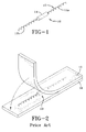
- the tag 10 is configured having a dipole antenna 12 have waving antenna segments 12A and 12B electrically and mechanically connected to the tag electronics 14. As shown in FIG. 2 , representing a prior art packaging approach, the tag 10 may be sandwiched between two gum strips 16, 18 that protect the tag yet do not interfere electrically with the operation of the tag.
- the present invention contemplates a method and construction of a tag package to include the application of liquid rubber compound 20 to the tag 10 as will be appreciated from FIGS. 4 , 5 , 6 , and 7 .
- the application of the liquid rubber compound 20 may be means of an applicator apparatus 22 or achieved by means of a dipping procedure.
- a rubber coating layer 24 results which encapsulates the entirety of the tag 10 is shown in FIG. 4 .
- the relatively thin layer 24 preferably having a thickness in a range of from 0.1 to 1 mm closely adheres to the antenna segments 12A and 12B as well as the electronics module 14 and serves to protect the structural integrity of the tag 10 and the connections between the antenna 12 and electronics module 14.
- the tag 10 including the rubber outer layer 24 may be attached to a surface 28 by the placement of a base strip of adhesive material 26 such as epoxy to the surface 28.
- the tag 10 is thereafter embedded into the base strip 26.
- an encapsulating strip 32 of adhesive material is applied across the embedded tag 10 by means of an applicator nozzle 30.
- the tag 10 is thus encapsulated in its entirety by the adhesive material 32 including base strip 26.
- the tag 10 adheres to the surface 28 free of electrical interference from the rubber coating layer 24 and the epoxy adhesive layer 32.
- the surface 28 be a non-metallic surface of the vehicle so as not to interfere with operation of the tag 10.
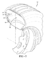
- One possible mounting location is to a tire 34 of the vehicle as schematically shown by FIG. 7 .
- the tag 10 may be affixed by the epoxy adhesive layer 32 to an inner liner 38 of the tire surrounding a tire inner cavity 36. So positioned, the tag 10 may transmit data from the tire location to a remote receiver.
- FIG. 8 shows an alternative means for attaching the tag 10 to a tire 34.
- the tag 10 is incorporated into the rubber material of the tire tread 40 during tire manufacture.
- the rubber coating 24 surrounding the tag 10 may be compounded to be compatible with such a placement into the tire rubber.
- the tag 10 is located to facilitate data transmission from the tire to an external reader.
- the tag 10 may alternatively be attached to a body surface of a car 42, such as but not limited to a car bumper surface 44.
- FIG. 9 shows an attachment of a prior art tag 46 to a car bumper 44.
- the tag 46 is encased within a metallic housing that is mounted to the vehicle by mounting holes drilled through the mounting surface.
- the housing of the tag 46 may be weather resistant; however, the necessity for mounting holes through a vehicle surface is undesirable and may be prohibited in the case of a leased vehicle.
- the housing of conventionally configured tags 46 requires a metal backplate to operate efficiently. The backplate reflects a signal from the tag 46 outward in a pattern such as the pattern 48 represented by FIG. 11.
- the data transmission signal in the pattern 48 is forwardly directed, meaning that the vehicle must more or less face the remote receiver in order to ensure the veracity of a transmission. Furthermore, the metal backplate behind prior art configured tags 46 limits the ability to read/write to the tag 46 from the side where the metal backplate is located.
- the present invention tag 10 overcomes the limitations of the prior art by providing a tag package and mounting method that does not require vehicle modification.
- the mounting procedure utilizes a caulking type adhesive to embed and mount the tag 10 on the vehicle.
- the tag 10 is configured having a dipole antenna that provides substantially 360 degree read/write capability when mounted on a non-metallic surface and provides increased read/write capability on a metallic backplate over the commercially available prior art vehicle tags.
- FIG. 10 shows a vehicle body based mounting location for the tag 10, on the bumper 44.
- mounting the tag 10 to the bumper 44 by the adhesive epoxy layer 32 is simpler, less expensive, and less invasive to the vehicle than the screw on attachment technique of the prior art. As shown in FIG.
- the result of mounting the dipole antenna configured tag to a vehicle non-metallic surface is that the tag 10 provides substantially 360 degree read/write capability as shown by the spherical pattern 50. Placement of the receiver (not shown) relative to the vehicle is accordingly not as critical as prior art tags conventionally mounted and the veracity of transmitted data is improved through the practice of the invention.
- the invention provides an electronic tag configuration 10 for a vehicle that includes an antenna 12; a data transmitter 14 coupled to the antenna; and an elastomeric coating layer 24 encapsulating the transmitter and antenna.
- the tag 10 may attach to the vehicle by means of a tire 34 or otherwise affixed to a body surface 44 of the vehicle.
- the antenna is preferably configured as a dipole that facilitates data transmission to and from an external transponder from substantially a 360 degree sphere surrounding the tag package.
- An adhesive material layer 26 may be included to encapsulate the tag, including the elastomeric material coated transmitter 14 and antenna 12.
- the invention further provides a method for tagging a vehicle with an electronic tag 10, and includes: coupling a data transmitter 14 to an antenna 12 configured as a dipole accessible to an externally originating signal from substantially a 360 degree sphere surrounding the tag 10; encapsulating the transmitter and antenna within an elastomeric coating layer 24; and affixing the encapsulated transmitter and antenna to a vehicle. Attachment of the encapsulated transmitter and antenna may be made to a tire of the vehicle or to the vehicle body.
- the method may include encapsulating the elastomeric layer coated transmitter and antenna within an outer adhesive material layer 32; and utilizing the outer adhesive material layer 32 to attach the transmitter and antenna to a vehicle component such as, but not limited to, a non-metallic surface of the vehicle.
Landscapes
- Engineering & Computer Science (AREA)
- Computer Hardware Design (AREA)
- Microelectronics & Electronic Packaging (AREA)
- Physics & Mathematics (AREA)
- General Physics & Mathematics (AREA)
- Theoretical Computer Science (AREA)
- Tires In General (AREA)
- Arrangements For Transmission Of Measured Signals (AREA)
Abstract
An electronic tag (10, 46) for a vehicle (42) includes an antenna (12); a data transmitter (14) coupled to the antenna (12); and an elastomeric coating layer (24) encapsulating the data transmitter and antenna. The tag may attach to the vehicle by means of a tire (34) or otherwise affixed to the body of the vehicle. The antenna may be configured as a dipole accessible by an external signal from substantially a 360 degree sphere surrounding the tag package. An adhesive material layer (32) may be included to encapsulate the elastomeric material coated data transmitter and antenna and utilized to attach the tag to a vehicle component.
Description
- The invention relates generally to RFID tags for vehicle tagging and, more specifically, to packaging configurations for such tags.
- Currently, vehicle tags are available which are weatherproof but which require mounting holes to be drilled on the vehicle. Such modification to the vehicle is undesirable. In addition, commercially available vehicle tags require a separate or an integral metal back plate to operate efficiently. A back plate, however, limits the ability to read/write to the tag from the side where the metal back plate exists. This limitation decreases the utility of the RFID tag and its range of intended applications.
- The invention relates to an electronic tag according to claim 1, a tire according to claim 6, a vehicle according to claim 9 and a method according to claim 11.
- Dependent claims refer to preferred embodiments of the invention.
- According to an aspect of the invention, an electronic tag for a vehicle includes
an antenna; a data transmitter coupled to the antenna; and an elastomeric coating layer encapsulating the transmitter and antenna. The tag may attach to the vehicle by means of a tire or otherwise affixed to the body of the vehicle. - In another aspect, the antenna is configured as a dipole accessible by an external signal from substantially a 360 degree sphere surrounding the tag package. An adhesive material layer may be included to encapsulate the elastomeric material coated transmitter and antenna.
- Pursuant to a further aspect of the invention, a method for tagging a vehicle with an electronic tag is provided and includes: coupling a data transmitter to an antenna configured as a dipole accessible to an externally originating signal from substantially a 360 degree sphere surrounding the tag; encapsulating the transmitter and antenna within an elastomeric coating layer; and affixing the encapsulated transmitter and antenna to a vehicle. The method may further include attaching the encapsulated transmitter and antenna to a tire of the vehicle.
- The method in another aspect may include encapsulating the elastomeric layer coated transmitter and antenna within an outer adhesive material layer; and utilizing the outer adhesive material layer to attach the transmitter and antenna to a vehicle component such as, but not limited to, a non-metallic surface of the vehicle.
- "Innerliner" means the layer or layers of elastomer or other material that form the inside surface of a tubeless tire and that contain the inflating fluid within the tire.
- The invention will be described by way of example and with reference to the accompanying drawings in which:
-
FIG. 1 is a RFID dipole configured tag pursuant to the invention prior to coating; -
FIG. 2 is a tag package alternative to that shown inFIG. 1 showing a two piece gum strip and tag construction. -
FIG. 3 is a depiction of the RFID tag ofFIG. 1 being covered by a liquid rubber spray application; -
FIG. 3A is a view illustrating the application of a rubber compound to the tag by means of a dipping procedure; -
FIG. 4 is a longitudinal side sectional view of a rubber coated RFID tag; -
FIG. 5 is a schematic view of the RFID tag affixed to a surface by means of epoxy resin application; -
FIG. 6 is a schematic view of an epoxy coat applied to fully enclose a tag; -
FIG. 7 is a schematic view of a tag affixed to an inner surface of a tire pursuant to the invention. -
FIG. 8 is a schematic view of a tag incorporated into the construction of a tire pursuant to the invention. -
FIG. 9 is a schematic view of a prior art method of attachment of a tag to a vehicle. -
FIG. 10 is a schematic view of the attachment of an RFID tag to a vehicle pursuant to the invention. - FIG. 11 is a schematic representation of the tag transmission directional pattern of a tag attached pursuant to
FIG. 9 . - FIG. 12 is a schematic representation of the tag transmission directional pattern of a tag attached pursuant to
FIG. 10 . - Referring initially to
FIGS. 1 and 2 , the subject invention relates to atag 10 for vehicle tagging. Thetag 10 is an RFID device for conveying vehicle related data from the vehicle to a remote receiver (not shown). Such information may include vehicle identification data, data correlating vehicle components such as tires with the vehicle, ownership information, etc. The data so conveyed may be used to determine and track the location of the vehicle. The capability of tracking a vehicle is particularly useful in commercial fleet applications where the vehicle is a truck or a bus. The receiver(s) located to receive data transmissions my convey such data to a central computer for storage and/or processing. Thetag 10 may be a read-only device or may also include a write capability for receiving and storing data transmitted from a remote transmitter. - The tag, or transponder, 10 is intended to be mounted to either a tire on the vehicle or to a vehicle surface. The mounting method as will be explained is weatherproof, easily installed, and provides read/write access covering the majority of a 360 degree sphere provided the
tag 10 is mounted to a non-metallic surface. Thetag 10 mounts in such a manner that does not require modifications to the vehicle which is of significant importance because some vehicles may be leased and permanent modifications to the vehicle contractually proscribed. - The
tag 10 is configured having adipole antenna 12 have waving antenna segments 12A and 12B electrically and mechanically connected to thetag electronics 14. As shown inFIG. 2 , representing a prior art packaging approach, thetag 10 may be sandwiched between twogum strips - The present invention contemplates a method and construction of a tag package to include the application of
liquid rubber compound 20 to thetag 10 as will be appreciated fromFIGS. 4 ,5 ,6 , and7 . The application of theliquid rubber compound 20 may be means of anapplicator apparatus 22 or achieved by means of a dipping procedure. Arubber coating layer 24 results which encapsulates the entirety of thetag 10 is shown inFIG. 4 . The relativelythin layer 24 preferably having a thickness in a range of from 0.1 to 1 mm closely adheres to the antenna segments 12A and 12B as well as theelectronics module 14 and serves to protect the structural integrity of thetag 10 and the connections between theantenna 12 andelectronics module 14. - As depicted in
FIGS. 5 and 6 , thetag 10 including the rubberouter layer 24 may be attached to asurface 28 by the placement of a base strip of adhesive material 26 such as epoxy to thesurface 28. Thetag 10 is thereafter embedded into the base strip 26. Thereafter, anencapsulating strip 32 of adhesive material is applied across the embeddedtag 10 by means of an applicator nozzle 30. Thetag 10 is thus encapsulated in its entirety by theadhesive material 32 including base strip 26. Thetag 10 adheres to thesurface 28 free of electrical interference from therubber coating layer 24 and the epoxyadhesive layer 32. - It is preferable that the
surface 28 be a non-metallic surface of the vehicle so as not to interfere with operation of thetag 10. One possible mounting location is to atire 34 of the vehicle as schematically shown byFIG. 7 . Thetag 10 may be affixed by the epoxyadhesive layer 32 to aninner liner 38 of the tire surrounding a tireinner cavity 36. So positioned, thetag 10 may transmit data from the tire location to a remote receiver.FIG. 8 shows an alternative means for attaching thetag 10 to atire 34. In theFIG. 8 approach, thetag 10 is incorporated into the rubber material of thetire tread 40 during tire manufacture. Therubber coating 24 surrounding thetag 10 may be compounded to be compatible with such a placement into the tire rubber. Positioned within thetread 40, thetag 10 is located to facilitate data transmission from the tire to an external reader. - The
tag 10 may alternatively be attached to a body surface of acar 42, such as but not limited to acar bumper surface 44.FIG. 9 shows an attachment of aprior art tag 46 to acar bumper 44. Thetag 46 is encased within a metallic housing that is mounted to the vehicle by mounting holes drilled through the mounting surface. The housing of thetag 46 may be weather resistant; however, the necessity for mounting holes through a vehicle surface is undesirable and may be prohibited in the case of a leased vehicle. In addition, the housing of conventionally configuredtags 46 requires a metal backplate to operate efficiently. The backplate reflects a signal from thetag 46 outward in a pattern such as the pattern 48 represented by FIG. 11. The data transmission signal in the pattern 48 is forwardly directed, meaning that the vehicle must more or less face the remote receiver in order to ensure the veracity of a transmission. Furthermore, the metal backplate behind prior art configured tags 46 limits the ability to read/write to thetag 46 from the side where the metal backplate is located. - The
present invention tag 10 overcomes the limitations of the prior art by providing a tag package and mounting method that does not require vehicle modification. The mounting procedure utilizes a caulking type adhesive to embed and mount thetag 10 on the vehicle. Thetag 10 is configured having a dipole antenna that provides substantially 360 degree read/write capability when mounted on a non-metallic surface and provides increased read/write capability on a metallic backplate over the commercially available prior art vehicle tags.FIG. 10 shows a vehicle body based mounting location for thetag 10, on thebumper 44. As will be appreciated, mounting thetag 10 to thebumper 44 by theadhesive epoxy layer 32 is simpler, less expensive, and less invasive to the vehicle than the screw on attachment technique of the prior art. As shown in FIG. 12, the result of mounting the dipole antenna configured tag to a vehicle non-metallic surface is that thetag 10 provides substantially 360 degree read/write capability as shown by the spherical pattern 50. Placement of the receiver (not shown) relative to the vehicle is accordingly not as critical as prior art tags conventionally mounted and the veracity of transmitted data is improved through the practice of the invention. - From the forgoing, it will be understand that the invention provides an
electronic tag configuration 10 for a vehicle that includes anantenna 12; adata transmitter 14 coupled to the antenna; and anelastomeric coating layer 24 encapsulating the transmitter and antenna. Thetag 10 may attach to the vehicle by means of atire 34 or otherwise affixed to abody surface 44 of the vehicle. The antenna is preferably configured as a dipole that facilitates data transmission to and from an external transponder from substantially a 360 degree sphere surrounding the tag package. An adhesive material layer 26 may be included to encapsulate the tag, including the elastomeric material coatedtransmitter 14 andantenna 12. - The invention further provides a method for tagging a vehicle with an
electronic tag 10, and includes: coupling adata transmitter 14 to anantenna 12 configured as a dipole accessible to an externally originating signal from substantially a 360 degree sphere surrounding thetag 10; encapsulating the transmitter and antenna within anelastomeric coating layer 24; and affixing the encapsulated transmitter and antenna to a vehicle. Attachment of the encapsulated transmitter and antenna may be made to a tire of the vehicle or to the vehicle body. The method may include encapsulating the elastomeric layer coated transmitter and antenna within an outeradhesive material layer 32; and utilizing the outeradhesive material layer 32 to attach the transmitter and antenna to a vehicle component such as, but not limited to, a non-metallic surface of the vehicle.
Claims (14)
- An electronic tag (10, 46) for a vehicle (42) comprising:an antenna (12);a data transmitter (14) coupled to the antenna (12);an elastomeric coating layer (24) substantially encapsulating the transmitter (14) and antenna (12).
- The tag of claim 1, wherein the antenna (12) is configured as a dipole accessible by an external signal from substantially a 360 degree sphere surrounding the tag (10, 46).
- The tag of claim 1 or 2, wherein further comprising an adhesive material layer (32) substantially encapsulating the elastomeric coating layer (24).
- The tag of claim 3, wherein the adhesive material layer (32) is at least partially composed of an epoxy material.
- The tag of at least one of the previous claims, wherein the elastomeric coating layer (24) is at least partially composed of a rubber material.
- A tire comprising an electronic tag (10, 46) according to one of the previous claims.
- The tire of claim 6 wherein the tag (10, 46) is attached to an inner liner (38) of the tire (34).
- The tire of claim 6 wherein the tag is incorporated into the rubber material of the tread (40) of the tire (34).
- A vehicle comprising an electronic tag (10, 46) according to one of the claims 1 to 5.
- The vehicle according to claim 5 wherein the tag (10, 46) is attached to a preferably non-metallic body surface (44) of the car (42).
- A method for tagging a vehicle with an electronic tag (10, 46), the method comprising:coupling a data transmitter (14) to an antenna (12) configured as a dipole and accessible to an externally originating signal from substantially a 360 degree sphere;at least substantially encapsulating the data transmitter (14) and the antenna (12) within an elastomeric coating layer (24);affixing the encapsulated data transmitter (14) and antenna (12) to a vehicle (42).
- The method of claim 10, further comprising attaching the encapsulated data transmitter (14) and antenna (12) to a tire (34) of the vehicle (42).
- The method of claim 11 or 12, further comprising substantially encapsulating the elastomeric layer coated data transmitter (14) and antenna (12) within an outer adhesive material layer (32); and utilizing the outer adhesive material layer (32) to attach the data transmitter (12) and antenna (14) to the vehicle (42).
- The method of claim 13, further comprising attaching the data transmitter (12) and antenna (14) to a non-metallic surface (44) of the vehicle (42).
Applications Claiming Priority (1)
| Application Number | Priority Date | Filing Date | Title |
|---|---|---|---|
| US12/164,172 US20090322480A1 (en) | 2008-06-30 | 2008-06-30 | Rfid tag and method of vehicle attachment thereof |
Publications (1)
| Publication Number | Publication Date |
|---|---|
| EP2141638A2 true EP2141638A2 (en) | 2010-01-06 |
Family
ID=41171062
Family Applications (1)
| Application Number | Title | Priority Date | Filing Date |
|---|---|---|---|
| EP09163583A Withdrawn EP2141638A2 (en) | 2008-06-30 | 2009-06-24 | RFID tag and method of vehicle attachment thereof |
Country Status (3)
| Country | Link |
|---|---|
| US (1) | US20090322480A1 (en) |
| EP (1) | EP2141638A2 (en) |
| BR (1) | BRPI0901932A2 (en) |
Cited By (1)
| Publication number | Priority date | Publication date | Assignee | Title |
|---|---|---|---|---|
| WO2018036038A1 (en) * | 2016-08-26 | 2018-03-01 | 上海仪电智能电子有限公司 | Implantable electronic tag for tire and assembly process |
Families Citing this family (67)
| Publication number | Priority date | Publication date | Assignee | Title |
|---|---|---|---|---|
| US8389862B2 (en) | 2008-10-07 | 2013-03-05 | Mc10, Inc. | Extremely stretchable electronics |
| US8097926B2 (en) | 2008-10-07 | 2012-01-17 | Mc10, Inc. | Systems, methods, and devices having stretchable integrated circuitry for sensing and delivering therapy |
| EP2349440B1 (en) | 2008-10-07 | 2019-08-21 | Mc10, Inc. | Catheter balloon having stretchable integrated circuitry and sensor array |
| US9123614B2 (en) | 2008-10-07 | 2015-09-01 | Mc10, Inc. | Methods and applications of non-planar imaging arrays |
| WO2011041727A1 (en) | 2009-10-01 | 2011-04-07 | Mc10, Inc. | Protective cases with integrated electronics |
| EP2681538B1 (en) | 2011-03-11 | 2019-03-06 | Mc10, Inc. | Integrated devices to facilitate quantitative assays and diagnostics |
| US11948035B2 (en) | 2011-05-06 | 2024-04-02 | Neology, Inc. | RFID switch tag |
| US9159635B2 (en) | 2011-05-27 | 2015-10-13 | Mc10, Inc. | Flexible electronic structure |
| WO2013022853A1 (en) | 2011-08-05 | 2013-02-14 | Mc10, Inc. | Catheter balloon methods and apparatus employing sensing elements |
| US9757050B2 (en) | 2011-08-05 | 2017-09-12 | Mc10, Inc. | Catheter balloon employing force sensing elements |
| WO2013033724A1 (en) | 2011-09-01 | 2013-03-07 | Mc10, Inc. | Electronics for detection of a condition of tissue |
| WO2013052919A2 (en) | 2011-10-05 | 2013-04-11 | Mc10, Inc. | Cardiac catheter employing conformal electronics for mapping |
| CN102778223A (en) * | 2012-06-07 | 2012-11-14 | 沈阳理工大学 | License number cooperation target and monocular camera based automobile anti-collision early warning method |
| US9226402B2 (en) | 2012-06-11 | 2015-12-29 | Mc10, Inc. | Strain isolation structures for stretchable electronics |
| EP2866645A4 (en) | 2012-07-05 | 2016-03-30 | Mc10 Inc | CATHETER DEVICE COMPRISING A FLOW DETECTOR |
| US9295842B2 (en) | 2012-07-05 | 2016-03-29 | Mc10, Inc. | Catheter or guidewire device including flow sensing and use thereof |
| CN105008949A (en) | 2012-10-09 | 2015-10-28 | Mc10股份有限公司 | Conformal electronics integrated with apparel |
| US9171794B2 (en) | 2012-10-09 | 2015-10-27 | Mc10, Inc. | Embedding thin chips in polymer |
| US9706647B2 (en) | 2013-05-14 | 2017-07-11 | Mc10, Inc. | Conformal electronics including nested serpentine interconnects |
| US9372123B2 (en) | 2013-08-05 | 2016-06-21 | Mc10, Inc. | Flexible temperature sensor including conformable electronics |
| US10083385B2 (en) * | 2014-04-10 | 2018-09-25 | Neology, Inc. | Universal transponder |
| US10929835B2 (en) | 2013-08-13 | 2021-02-23 | Neology, Inc. | Detachable radio frequency identification switch tag |
| KR20160065948A (en) | 2013-10-07 | 2016-06-09 | 엠씨10, 인크 | Conformal sensor systems for sensing and analysis |
| EP3071096A4 (en) | 2013-11-22 | 2017-08-09 | Mc10, Inc. | Conformal sensor systems for sensing and analysis of cardiac activity |
| US10410962B2 (en) | 2014-01-06 | 2019-09-10 | Mc10, Inc. | Encapsulated conformal electronic systems and devices, and methods of making and using the same |
| CN106063392B (en) | 2014-03-04 | 2020-06-02 | Mc10股份有限公司 | Multi-part flexible enclosure for electronic devices |
| EP3117206A4 (en) | 2014-03-12 | 2017-11-15 | Mc10, Inc. | Quantification of a change in assay |
| US20160006123A1 (en) * | 2014-07-01 | 2016-01-07 | Mc10, Inc. | Conformal electronic devices |
| US9899330B2 (en) | 2014-10-03 | 2018-02-20 | Mc10, Inc. | Flexible electronic circuits with embedded integrated circuit die |
| US10297572B2 (en) | 2014-10-06 | 2019-05-21 | Mc10, Inc. | Discrete flexible interconnects for modules of integrated circuits |
| USD781270S1 (en) | 2014-10-15 | 2017-03-14 | Mc10, Inc. | Electronic device having antenna |
| US10525770B2 (en) | 2014-12-22 | 2020-01-07 | Bridgestone Americas Tire Operations, Llc | Rubber compositions for radio devices in tires |
| EP3258837A4 (en) | 2015-02-20 | 2018-10-10 | Mc10, Inc. | Automated detection and configuration of wearable devices based on on-body status, location, and/or orientation |
| WO2016140961A1 (en) | 2015-03-02 | 2016-09-09 | Mc10, Inc. | Perspiration sensor |
| US9691014B2 (en) | 2015-04-07 | 2017-06-27 | Neology, Inc. | Radio frequency identification tag in a license plate |
| US9764715B2 (en) | 2015-04-07 | 2017-09-19 | Neology, Inc. | License plate validation |
| US10653332B2 (en) | 2015-07-17 | 2020-05-19 | Mc10, Inc. | Conductive stiffener, method of making a conductive stiffener, and conductive adhesive and encapsulation layers |
| WO2017031129A1 (en) | 2015-08-19 | 2017-02-23 | Mc10, Inc. | Wearable heat flux devices and methods of use |
| WO2017059215A1 (en) | 2015-10-01 | 2017-04-06 | Mc10, Inc. | Method and system for interacting with a virtual environment |
| CN108289630A (en) | 2015-10-05 | 2018-07-17 | Mc10股份有限公司 | Method and system for nerve modulation and stimulation |
| ITUB20155322A1 (en) * | 2015-10-30 | 2017-04-30 | Pirelli | Process and apparatus for labeling tires for vehicle wheels |
| CN108699376A (en) | 2015-11-09 | 2018-10-23 | 普利司通美国轮胎运营有限责任公司 | For the rubber coating of electronic communications module, include the electronic module and associated method of the rubber coating |
| WO2017147052A1 (en) | 2016-02-22 | 2017-08-31 | Mc10, Inc. | System, devices, and method for on-body data and power transmission |
| CN108781313B (en) | 2016-02-22 | 2022-04-08 | 美谛达解决方案公司 | Systems, devices, and methods for coupled hubs and sensor nodes for on-body acquisition of sensor information |
| US11154235B2 (en) | 2016-04-19 | 2021-10-26 | Medidata Solutions, Inc. | Method and system for measuring perspiration |
| US10447347B2 (en) | 2016-08-12 | 2019-10-15 | Mc10, Inc. | Wireless charger and high speed data off-loader |
| DE102017010612A1 (en) * | 2017-11-16 | 2019-05-16 | Kuka Systems Gmbh | Method and device for applying a chip |
| JP2019099060A (en) * | 2017-12-06 | 2019-06-24 | 株式会社ブリヂストン | Tire theft monitoring system, tire theft monitoring device and tire theft monitoring method |
| CN108846468B (en) * | 2018-06-08 | 2024-12-17 | 深圳麦格米特电气股份有限公司 | Electronic tag system |
| EP3877910A4 (en) | 2018-11-07 | 2022-08-03 | Neology, Inc. | DETACHABLE RADIO FREQUENCY IDENTIFICATION SWITCH LABEL |
| USD1027615S1 (en) | 2022-07-25 | 2024-05-21 | Elevation Lab, Inc. | Device mount |
| USD1116733S1 (en) | 2022-07-25 | 2026-03-10 | Elevation Lab, Inc. | Tracking device mount |
| USD1028752S1 (en) | 2022-10-07 | 2024-05-28 | Elevation Lab, Inc. | Tracking device mount |
| USD1054886S1 (en) | 2023-01-30 | 2024-12-24 | Elevation Lab, Inc. | Tracker housing |
| USD1054887S1 (en) | 2023-01-30 | 2024-12-24 | Elevation Lab, Inc. | Tracker housing |
| USD1003748S1 (en) | 2023-02-21 | 2023-11-07 | Elevation Lab, Inc. | Tracker housing |
| USD1003747S1 (en) | 2023-02-21 | 2023-11-07 | Elevation Lab, Inc. | Tracker housing |
| USD1046651S1 (en) | 2023-06-29 | 2024-10-15 | Elevation Lab, Inc. | Tracking device mount |
| US11910888B1 (en) | 2023-06-30 | 2024-02-27 | Elevation Lab, Inc. | Mounts for tracking devices |
| US11934902B1 (en) * | 2023-08-21 | 2024-03-19 | Elevation Lab, Inc. | Mounts for tracking devices |
| USD1068510S1 (en) | 2023-08-21 | 2025-04-01 | Elevation Lab, Inc. | Tracker housing |
| US11931643B1 (en) | 2023-08-21 | 2024-03-19 | Elevation Lab, Inc. | Mounts for tracking devices |
| US12264773B1 (en) | 2024-01-05 | 2025-04-01 | Elevation Lab, Inc. | Tripod mounting plates for housing tracking devices |
| US12106167B1 (en) | 2024-04-30 | 2024-10-01 | Elevation Lab, Inc. | Housings for tracking devices |
| US12393817B1 (en) | 2025-01-07 | 2025-08-19 | Elevation Lab, Inc. | Housings for tracking devices |
| USD1138815S1 (en) | 2025-01-15 | 2026-08-04 | Elevation Lab, Inc. | Mount for tracking device |
| USD1115577S1 (en) | 2025-01-15 | 2026-03-03 | Elevation Lab, Inc. | Housing for tracking device |
Family Cites Families (13)
| Publication number | Priority date | Publication date | Assignee | Title |
|---|---|---|---|---|
| US5181975A (en) * | 1991-03-27 | 1993-01-26 | The Goodyear Tire & Rubber Company | Integrated circuit transponder with coil antenna in a pneumatic tire for use in tire identification |
| US5218861A (en) * | 1991-03-27 | 1993-06-15 | The Goodyear Tire & Rubber Company | Pneumatic tire having an integrated circuit transponder and pressure transducer |
| US6309494B1 (en) * | 1998-12-04 | 2001-10-30 | Bridgestone/Firestone Research, Inc. | Method of attaching sensitive electronic equipment to the inner surface of a tire |
| DE10223800A1 (en) * | 2002-05-29 | 2003-12-18 | Continental Ag | Transponder for installation in or on the surface of objects |
| US7104438B2 (en) * | 2003-10-22 | 2006-09-12 | The Goodyear Tire & Rubber Company | Method of integrating tire identification into a vehicle information system |
| US7017405B2 (en) * | 2003-12-22 | 2006-03-28 | The Goodyear Tire & Rubber Company | System and method for post-cure application of electronics to a tire |
| US7126489B2 (en) * | 2004-12-20 | 2006-10-24 | The Goodyear Tire & Rubber Company | Guide mechanism and method for axially directing an annular transponder unit |
| US20060290505A1 (en) * | 2005-03-01 | 2006-12-28 | Kevin Conwell | RFID tire label |
| US20070107824A1 (en) * | 2005-11-16 | 2007-05-17 | Hahn Bruce R | Rubber formulation with adhesive-compatible surface |
| EP1984216A2 (en) * | 2005-12-15 | 2008-10-29 | THE GOODYEAR TIRE & RUBBER COMPANY | A method of determining vehicle properties |
| US20090151828A1 (en) * | 2007-12-15 | 2009-06-18 | Junling Zhao | Tire with antenna encapsulated with rubber compound containing thermoplastic |
| US8157172B2 (en) * | 2008-10-30 | 2012-04-17 | The Goodyear Tire & Rubber Company | RFID tag package and tire assembly |
| US8430142B2 (en) * | 2009-02-25 | 2013-04-30 | The Goodyear Tire & Rubber Company | Environmentally resistant assembly containing an electronic device for use in a tire |
-
2008
- 2008-06-30 US US12/164,172 patent/US20090322480A1/en not_active Abandoned
-
2009
- 2009-06-22 BR BRPI0901932-4A patent/BRPI0901932A2/en not_active IP Right Cessation
- 2009-06-24 EP EP09163583A patent/EP2141638A2/en not_active Withdrawn
Cited By (1)
| Publication number | Priority date | Publication date | Assignee | Title |
|---|---|---|---|---|
| WO2018036038A1 (en) * | 2016-08-26 | 2018-03-01 | 上海仪电智能电子有限公司 | Implantable electronic tag for tire and assembly process |
Also Published As
| Publication number | Publication date |
|---|---|
| US20090322480A1 (en) | 2009-12-31 |
| BRPI0901932A2 (en) | 2010-04-13 |
Similar Documents
| Publication | Publication Date | Title |
|---|---|---|
| US20090322480A1 (en) | Rfid tag and method of vehicle attachment thereof | |
| EP1459911A1 (en) | Tag attachment for tires and method of attaching tags to tires | |
| US7186308B2 (en) | System and method for providing tire electronics mounting patches | |
| US7405656B2 (en) | Device and method for encapsulation and mounting of RFID devices | |
| US5608391A (en) | Electronic license plate architecture | |
| EP3394635B1 (en) | Vehicle positioning with rfid tags | |
| US7659857B2 (en) | System and method for providing a low and narrow-profile radio frequency identification (RFID) tag | |
| US20050087593A1 (en) | Method of integrating tire identification into a vehicle information system | |
| US8339267B2 (en) | RFID device having protective cap element and method of making | |
| KR100791739B1 (en) | Wireless Integrated Circuit Tag Bonding Methods, Wireless Integrated Circuit Tag Attachments, and Vehicles | |
| US20050076982A1 (en) | Post patch assembly for mounting devices in a tire interior | |
| US20230034241A1 (en) | Rfid systems for use with tires | |
| EP3035248A1 (en) | Rfid tag and method for manufacturing same | |
| US20080289407A1 (en) | Use of Piezoelectric Sensor Attached to Electronics Package Housing | |
| CA3094893C (en) | Vehicle identification means | |
| US20080106415A1 (en) | Information tag | |
| US9379289B1 (en) | LEDs on adhesive transfer tape | |
| CN110534868B (en) | Vehicle window glass, preparation method thereof and vehicle | |
| KR20080049008A (en) | Shipping container vent cover antenna housing | |
| US20060208905A1 (en) | Panel | |
| US20070052522A1 (en) | Window glass for vehicle, and attachment structure of electronic tag | |
| CN108171310A (en) | A kind of compound RFID label tag | |
| US11142028B2 (en) | Electronic unit for measuring operating parameters of a vehicle wheel | |
| US10402713B1 (en) | RF transponder on adhesive transfer tape | |
| KR200434463Y1 (en) | RDF adapter package block and RDF tag using the same |
Legal Events
| Date | Code | Title | Description |
|---|---|---|---|
| PUAI | Public reference made under article 153(3) epc to a published international application that has entered the european phase |
Free format text: ORIGINAL CODE: 0009012 |
|
| AK | Designated contracting states |
Kind code of ref document: A2 Designated state(s): AT BE BG CH CY CZ DE DK EE ES FI FR GB GR HR HU IE IS IT LI LT LU LV MC MK MT NL NO PL PT RO SE SI SK TR |
|
| STAA | Information on the status of an ep patent application or granted ep patent |
Free format text: STATUS: THE APPLICATION HAS BEEN WITHDRAWN |
|
| 18W | Application withdrawn |
Effective date: 20121031 |