EP2141528A1 - Optical fibre distribution box - Google Patents
Optical fibre distribution box Download PDFInfo
- Publication number
- EP2141528A1 EP2141528A1 EP09251715A EP09251715A EP2141528A1 EP 2141528 A1 EP2141528 A1 EP 2141528A1 EP 09251715 A EP09251715 A EP 09251715A EP 09251715 A EP09251715 A EP 09251715A EP 2141528 A1 EP2141528 A1 EP 2141528A1
- Authority
- EP
- European Patent Office
- Prior art keywords
- layer
- fibre
- distribution box
- cable
- optical fibre
- Prior art date
- Legal status (The legal status is an assumption and is not a legal conclusion. Google has not performed a legal analysis and makes no representation as to the accuracy of the status listed.)
- Granted
Links
- 238000009826 distribution Methods 0.000 title claims abstract description 91
- 239000013307 optical fiber Substances 0.000 title claims abstract description 25
- 239000000835 fiber Substances 0.000 claims abstract description 82
- 230000003287 optical effect Effects 0.000 claims description 23
- 239000010410 layer Substances 0.000 description 159
- 230000008859 change Effects 0.000 description 3
- 230000000452 restraining effect Effects 0.000 description 3
- 230000008901 benefit Effects 0.000 description 2
- 230000001419 dependent effect Effects 0.000 description 2
- 230000000717 retained effect Effects 0.000 description 2
- 239000002356 single layer Substances 0.000 description 2
- 230000007704 transition Effects 0.000 description 2
- 229920000271 Kevlar® Polymers 0.000 description 1
- 238000010276 construction Methods 0.000 description 1
- 239000000428 dust Substances 0.000 description 1
- 238000005516 engineering process Methods 0.000 description 1
- 230000007613 environmental effect Effects 0.000 description 1
- 239000004761 kevlar Substances 0.000 description 1
- 238000000034 method Methods 0.000 description 1
- 230000004048 modification Effects 0.000 description 1
- 238000012986 modification Methods 0.000 description 1
- 238000010079 rubber tapping Methods 0.000 description 1
- XLYOFNOQVPJJNP-UHFFFAOYSA-N water Substances O XLYOFNOQVPJJNP-UHFFFAOYSA-N 0.000 description 1
Images






Classifications
-
- G—PHYSICS
- G02—OPTICS
- G02B—OPTICAL ELEMENTS, SYSTEMS OR APPARATUS
- G02B6/00—Light guides; Structural details of arrangements comprising light guides and other optical elements, e.g. couplings
- G02B6/46—Processes or apparatus adapted for installing or repairing optical fibres or optical cables
- G02B6/47—Installation in buildings
- G02B6/475—Mechanical aspects of installing cables in ducts or the like for buildings
-
- G—PHYSICS
- G02—OPTICS
- G02B—OPTICAL ELEMENTS, SYSTEMS OR APPARATUS
- G02B6/00—Light guides; Structural details of arrangements comprising light guides and other optical elements, e.g. couplings
- G02B6/44—Mechanical structures for providing tensile strength and external protection for fibres, e.g. optical transmission cables
- G02B6/4439—Auxiliary devices
- G02B6/444—Systems or boxes with surplus lengths
- G02B6/4453—Cassettes
Definitions
- the present invention relates to an optical fibre distribution box.
- the present invention relates to a modular optical distribution box for use in a passive optical network.
- Optical fibre distribution boxes are known.
- outside service provider cables from a provider are routed to the office and it is necessary to further route individual optical fibres or fibre bundles coupled to the outside service provider cables to individual end users.
- the cables from the provider pass through building distribution boxes, typically provided in the basement, and/or distribution cabinets provided throughout the building.
- an outside provider cable is routed, via a building distribution box, to riser cables which feed individual dwelling units (such as apartments or offices) within the multiple dwelling unit.
- the space available for the optical network or distribution system within a multiple dwelling unit (MDU) is typically particularly limited, especially within a services riser shaft carrying the riser cables.
- one aspect of the present invention provides a modular optical fibre distribution box operable to receive a fibre from a fibre optic cable and to distribute said fibre to a user, said fibre distribution box comprising a plurality of stackable layers, said layers including a first layer configured to receive said fibre optic cable, and a second layer configured to distribute said fibre to said user, said second layer being operable to engage with the first layer in a plurality of orientations.
- Provision of a set of layers, each layer providing a different function, allows for significant flexibility within the fibre distribution box. It is possible, for example, to extract a fibre from a cable on one layer of the distribution box and route it to another layer to perform a further operation, such as redirection to an end user, splicing to another fibre. Once re-routed to a second layer, the first layer may be substantially closed by the addition of a further layer. In some situations this can have the advantage that the first layer is then substantially closed and further work need only be carried out on the additional layer.
- each layer can be of reduced dimension. Provision of all functions within a single layer necessarily requires a particular relative arrangement of the functional features of a layer.
- the second layer is operable to engage with the first layer in a plurality of orientations allows for increased flexibility in terms of assembly of the stackable fibre distribution box in a limited space environment. Such an arrangement also allows for improved ease of construction for any operative assembling said distribution box within a riser, for example, reorientation of the second layer on the first layer may quickly and easily provide a way to change the direction in which fibres leave the second layer to reach an end user, without the requirement for a different layer.
- Each layer may include only one working surface. That working surface may be the front face of a layer. Provision of a layer that has only one working surface allows an operative to work more easily on each layer of the stack. The operative only requires access to the front face of a layer to complete work on that layer.
- Each layer may perform a number of functions, and/or each layer may offer a number of ways to perform a particular function.
- the cable may be arranged to pass through that layer and continue to another destination in a substantially linear manner, or may, for example, be redirected by the first layer and perform a 180 degree change of direction.
- the first layer may provide an area for storage of overlength fibre.
- the second layer may be configured to distribute the fibre to the user in a number of ways. It will be understood that the second layer may include various passive optical components including, for example, a splice, a multiplexing unit or a splitter. Said second layer may include a receiving and retaining means to hold a passive optical component in position on the second layer.
- the second layer may further comprise an output port on at least one side, that output port being arranged to direct said fibres towards a user. Provision of an output port on at least one side, coupled with the ability to engage the second layer with first layer in a plurality of orientations, allows for an operative to change the direction in which fibres exit the second layer and are directed to an end user without requiring a different second layer.
- the outlet port could be configured such that the fibres exit the modular distribution box on the left hand side, or if the second layer is rotated 180 degrees with respect to the first layer then the fibres may be directed to a user from the right hand side of the optical fibre distribution box. If rotated 90 degrees or 270 degrees with respect to the first orientation, the fibres may exit the second layer the fibre distribution box substantially aligned with the longitudinal access of the cable i.e. at the top or at the bottom of the fibre distribution box. This positional flexibility can be provided with a single suitably arranged second layer.
- the outlet port of the second layer may include a receiving port which is arranged to receive a termination unit. Provision of a receiving portion to receive termination unit allows the same second layer to be used for a variety of termination units including, for example, optical adaptors, tie off points and/or simply tap off distribution ports.
- the termination unit may include a plurality of fibre outlets. A termination unit may be inserted into the receiving portion in the outlet port, or may be integrally formed with the outlet port of the second layer.
- the second layer may be further configured to engage and stack with a third layer, said third layer being configured to receive a fibre and distribute said fibre to said user.
- Provision of a series of layers that can stack allows the fibre distribution box to be substantially future-proof. Furthermore, it allows for increased flexibility within the optical fibre distribution box since an operative using the distribution box may, for example, arrange that two fibres can leave the distribution box from the second layer using fibre adaptors and a further four, for example, fibres may leave the distribution box from the third layer from termination ports.
- Such an arrangement of stackable layers is therefore particularly adaptable and flexible and the needs of an operative and end users may be met by growing the set of stackable layers within the distribution box to suit the requirements of any given location.
- the first layer may further comprise a fibre routing gap which is connectable to any one of the other layers of the stack. In this manner a fibre or fibre bundle from the cable can be routed directly to the layer in which it is required and not routed via any other layers.
- the second layer and the third layer may be substantially identical. Such an arrangement has the advantage that only two different layers need be provided. Further second layers may be provided to an operative as fibre distribution box extension kits. If the layers are substantially identical, the distribution box is simply growable to the correct size for the applicable intended.
- the modular optical fibre distribution box may further include a transition layer which enables two substantially identical layers to be stacked as described above. A third transition layer may act to protect the contents of the first or second layers.
- One or more layers of the modular optical fibre distribution box may include a receiving channel for routing the fibre between layers.
- Each layer may be provided with one or more receiving channels.
- Those receiving channels may be substantially symmetrically disposed around a layer such that the layer may route a fibre between layers when the layer is in any one of a plurality of orientations.
- the receiving channel may be provided along an edge of a layer. Provision of a receiving channel for routing fibres between layers assist the growability of the modular fibre distribution box.
- At least one layer may include a securing portion arranged to locate and secure the passive optical component on said layer.
- a second layer of an optical fibre distribution box in accordance with the present invention may simply be used as a tapping off layer.
- a tap off layer simply re-routes a fibre from a cable directly to a user, without passing through an optical component, for example, a splice.
- optical fibre routed from the cable may, however, be spliced in the second layer before being re-routed to an end user. Provision of a securing portion arranged to locate and secure the passive optical component on a second layer thus allows for increased flexibility for an operative installing an optical fibre distribution box without the requirement for a specific layer for each possible passive optical component.
- a modular optical fibre distribution box may further comprise a cover layer. That cover layer provides protection to fibres housed in the optical fibre distribution box from dust, water ingress and forces applied to fibres leaving the distribution box.
- FIG. 1 illustrates a cable distribution arrangement 1000.
- a central office 1010 associated with a service provider is coupled with a distribution point 1020 by an outside service provider cable 1015.
- Distribution point 1020 may be coupled with further distributions points (not shown) using outside service provider distribution cables 1023 and 1027.
- the distribution point 1020 couples with one or more multiple dwelling units 1030, 1040, 1050, using an outside service provider distribution cable 1025.
- the outside service provider distribution cable 1025 loops through each multiple dwelling unit 1030, 1040, 1050 in turn.
- the outside service provider distribution cable 1025 may also loop through further multiple dwelling units (not shown). In this way, it can be seen that the service provider couples via an optical network with the multiple dwelling units 1030, 1040, 1050. Details of how the outside service provider distribution cable 1025 is then utilised within the multiple dwelling units 1030, 1040, 1050 are described below, with reference to Figure 3 .
- FIG. 2 illustrates a typical arrangement of an optical cable 1100, such as would be utilised for the outside service provider cable 1015, the outside service provider distribution cables 1023, 1025, 1027, or for cables utilised within the multiple dwelling units 1030, 1040, 1050.
- the cable 1100 comprises an outer jacket 1110 which provides for appropriate environmental protection of the cable 1100.
- Disposed within the cable jacket 1110 is a plurality of tubes 1120.
- Within the tubes 1120 are provided one or more individual fibres 1130. Typically 16 or 32 individual fibres 1130 may be provided within a single tube 1120.
- a braided Kevlar (registered trade mark) strand may be provided within cable 1100 which may be mechanically coupled with a pulling tool to assist in routing the cable.
- Figure 3 illustrates an arrangement of a multiple dwelling unit building distributor 1210 for dwelling unit 1030 according to one embodiment.
- the multiple dwelling unit 1030 comprises a single dwelling unit 1200A-1200F on each floor.
- more than one dwelling unit may be provided on each floor of the building.
- the other multiple dwelling units 1040, 1050 will generally have a similar general layout, although the number of floors and the number of dwelling units on each floor may vary from multiple dwelling unit to multiple dwelling unit.
- the multiple dwelling unit building distributor 1210 receives the outside surface provider distribution cable 1025.
- One or more fibres 1130 from the outside service provider distribution cable 1025 are pulled from the outside service provider distribution cable 1025 and typically coupled with a splitter 1220.
- the splitter 1220 takes a single fibre 1130 and couples this fibre, typically using splicing techniques, with a plurality N of pigtail cables 1225.
- the plurality of pigtail cables 1225 are provided to a patching arrangement 1230 which enables the plurality of pigtails 1225 to be selectively coupled with a riser cable 1230 comprising a plurality M of fibres which leaves the multiple dwelling unit building distributor 1210.
- the riser cable 1230 is routed through a building region 1240 to a riser 1250.
- the building region 1240 may be, for example, a basement area of the multiple dwelling unit 1030.
- the riser cable 1230 may be surface mounted in the building region 1240.
- the riser 1250 will typically be a service conduit within the multiple dwelling unit 1030 extending from the basement to the under-roof region of the building. The riser 1250 will therefore extend between the floors of the multiple dwelling unit 1030.
- one or more fibres 1260A-1260F may be pulled from the riser cable 1230 in order to provide connectivity within the individual dwelling units 1200A-1200F.
- User equipment 1270A may then couple with the associated fibres 1260, as required.
- arrangement enables user equipment within individual dwelling units to be coupled via the optical network with the service providers. Also, the presence of the patch arrangement 1230 within the multiple dwelling unit buildi ng distributor 1210 enables connectivity with different service providers to be achieved.
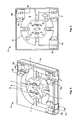
- Figures 4 and 5 show a first layer of a modular fibre distribution box in accordance with the present invention.
- the first layer 1 is substantially square in shape and substantially flat.
- One side includes a cable inlet port 2 and there are also provided two cable outlet ports 3.
- the first cable outlet port 3a is provided such that a cable, such as a riser cable 1230, can be routed straight through the layer 1.
- the second cable outlet port 3b is located for the instances in which a cable is to pass through 180 degrees before exiting the layer 1.
- Each of the outlet ports 3a, 3b includes a 'push-out' element 4a, 4b which may be pushed out when it is intended to use that particular output port.
- the inlet and outlet ports each have adjacent to them a restraining region 5a, 5b, 5c. In those restraining regions, a cable passing through the layer may be secured with respect to the layer. In the embodiment shown, each of those regions include openings for receiving a cable tie.
- the interior region of layer 1 further includes a cable guide channel 6 which assists in guiding a cable entering the first layer from the inlet port to either of the outlet ports 3a, 3b.
- the guide channel 6 is dimensioned such that a cable entering the inlet port and performing a 180 degree turn does not exceed the minimum bend radius of any fibres contained therein.
- retaining tabs 7 Located over the cable guide channel there are a series of retaining tabs 7. Those cable tabs act to secure the cable, or fibres extracted from the cable, within the guide channel 6.
- the first layer 1 also includes a number of alignment pins 8 for alignment of the first layer with the second layer and a number of securing pins 9 securing a second layer with respect to the first layer.
- the layer also includes a fibre routing gap 10. That fibre routing gap allows fibres or fibre bundles extracted from a cable passing through the first layer 1 to be rerouted to any other layer of a fibre distribution box.
- the first layer of the fibre distribution box is used by an operative to provides a base for a fibre distribution box at a point where it is intended to extract a fibre or fibres from a riser cable passing through a building 1230.
- an operative To perform this operation, it is necessary for an operative to remove a portion of the cable jacket 1110.
- An operative will remove a portion of the cable jacket, by making a cut known as a 'window cut' in the cable jacket. Making such a 'window cut' exposes fibres and fibre bundles 1120, 1130 housed within the riser cable 1230.
- the cable including the 'window cut' is routed through the first layer of the micro distribution box 1.
- a fibre or fibres to be routed to the end-users through the distribution box is extracted from the cable.
- the relevant fibres are extracted by pulling, for example, from the cable.
- the extracted fibres are routed towards the fibre routing gap 10 from where they can pass to other layers of the stackable modular micro distribution unit.
- the cable is secured in place within the first layer by cable ties provided in the restraining regions 5.
- FIGS. 6 and 7 illustrate a second layer for use in a fibre distribution box in accordance with the present invention.
- Said second layer includes a number of receiving channels 21 disposed around its edges. Those receiving channels are substantially symmetrically placed such that the second layer may be engaged and aligned with the first layer in a number of orientations.
- the second layer also includes a number of fibre guides 22 disposed within the layer such that a fibre entering from anyone of the receiving channels 21 may be guided around within the second layer without exceeding the minimum bend radius of the fibres.
- the fibres entering, or arranged within the second layer are retained in place by a series of retaining tabs 23 provided in various locations typically close to bend regions of the fibre such that the fibres are retained in place securely.
- the outlet region 26 allows fibres entering the second layer to exit the second layer and be directed towards an end-user.
- the outlet region includes two termination unit engagement pins 27 that are used to locate various termination units, shown in figures 8 and 9 in position on the second layer.
- the second layer may also include a passive optical component.
- That passive optical component may, for example, be a splice or splice together, though neither are shown in Figure 6 or Figure 7 . However, that optical component may be held in place on the second layer by component engaging elements 24.
- a fibre exits the first layer shown in Figures 4 and 5 via the fibre routing gap 10 and is routed towards one of the receiving channels provided in the second layer 21.
- the fibre(s) may then be directed from any one of the receiving channels towards an optical component provided in the component engaging elements 24 or may for example simply loop within the second layer towards the outlet port 26. Fibres exiting an optical component provided in the second layer are also routed by the guide means 22 towards the outlet region 26.
- the second layer is aligned and secured on the first layer by the alignment pins 8 engaging with the alignment opening 25 and securing pins 9 snap fit with the edge of alignment opening 25.
- FIGS 8 and 9 show various termination unit inserts 30 that may be inserted in the outlet region 26 of the second layer. It will be understood that those termination units may allow the second layer of the distribution box to have a connector patch connection outlet function, a tap off function or a fibre fixation function.
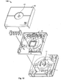
- Figure 10 is an exploded perspective view of a fibre distribution box in accordance with the present invention. It can be seen that the complete fibre distribution box further includes a cover layer 40 that fits over the second layer and protects the contents of the second layer of the fibre distribution box.
- the cover layer includes 40 includes the hole 41 that receives a box fastening device (not shown), for example a screw, that engages with a hole 11 provided on layer 1.
- This fastening device clamps all layers of the fibre distribution box together and allows the cover to more effectively protect the cable and the fibres contained therein from outside elements.
- the second layer 20 is shown in Figure 10 in a particular orientation with respect to the first layer 1, the second layer may be rotated through 90, 180 or 270 degrees and still engage with the first layer.
- Figure 11 shows another arrangement of the layers shown in previous figures.
- the fibre distribution box includes two second layers 20a, 20b arranged to direct fibres towards end-users.
- the layers are stacked by using an intermediate layer 50.
- the intermediate layer 50 includes a further set of alignment pins 8 and securing pins 9. It also includes an opening 51 for receiving a fibre or fibre bundle from a second layer 20a or first layer 1 so that those fibre or fibre bundles can be re-routed into a second layer 20b. It will be understood that the provision of the further intermediate layers and further second layers allows the further distribution box to grow to the size required.
Landscapes
- Physics & Mathematics (AREA)
- General Physics & Mathematics (AREA)
- Optics & Photonics (AREA)
- Engineering & Computer Science (AREA)
- Civil Engineering (AREA)
- Structural Engineering (AREA)
- Light Guides In General And Applications Therefor (AREA)
Abstract
Description
- The present invention relates to an optical fibre distribution box. In particular, the present invention relates to a modular optical distribution box for use in a passive optical network.
- Optical fibre distribution boxes are known. In a typical optical signal distribution system or network, such as that provided within an office, outside service provider cables from a provider are routed to the office and it is necessary to further route individual optical fibres or fibre bundles coupled to the outside service provider cables to individual end users. The cables from the provider pass through building distribution boxes, typically provided in the basement, and/or distribution cabinets provided throughout the building.
- In newer optical signal distribution networks, such as those provided within a multiple dwelling unit (such as a building or block of offices) an outside provider cable is routed, via a building distribution box, to riser cables which feed individual dwelling units (such as apartments or offices) within the multiple dwelling unit.
- The space available for the optical network or distribution system within a multiple dwelling unit (MDU) is typically particularly limited, especially within a services riser shaft carrying the riser cables.
- As the number of outside service provider fibres increase and as the take up of fibre technology increases, the number of fibres to be managed within the same available space, and the operations (for example, splices, tap offs etc) required to manage those fibres increases dramatically.
- Whilst various optical fibre distribution boxes exist, they each have certain shortfalls, for example, the space taken up by a fibre distribution box may be particularly inappropriate for a riser shaft environment, especially since either too many or too few connections to end users may be provided by a given size of distribution box and assembly of the distribution box may be particularly difficult within the limited space of a riser shaft.
- Accordingly, it is desired to provide an improved fibre distribution box.
- Accordingly, one aspect of the present invention provides a modular optical fibre distribution box operable to receive a fibre from a fibre optic cable and to distribute said fibre to a user, said fibre distribution box comprising a plurality of stackable layers, said layers including a first layer configured to receive said fibre optic cable, and a second layer configured to distribute said fibre to said user, said second layer being operable to engage with the first layer in a plurality of orientations.
- Provision of a set of layers, each layer providing a different function, allows for significant flexibility within the fibre distribution box. It is possible, for example, to extract a fibre from a cable on one layer of the distribution box and route it to another layer to perform a further operation, such as redirection to an end user, splicing to another fibre. Once re-routed to a second layer, the first layer may be substantially closed by the addition of a further layer. In some situations this can have the advantage that the first layer is then substantially closed and further work need only be carried out on the additional layer.
- It will be understood that since it is no longer the case that all functions to be performed by the fibre distribution box must be accommodated within a single layer, each layer can be of reduced dimension. Provision of all functions within a single layer necessarily requires a particular relative arrangement of the functional features of a layer.
- Ensuring that the second layer is operable to engage with the first layer in a plurality of orientations allows for increased flexibility in terms of assembly of the stackable fibre distribution box in a limited space environment. Such an arrangement also allows for improved ease of construction for any operative assembling said distribution box within a riser, for example, reorientation of the second layer on the first layer may quickly and easily provide a way to change the direction in which fibres leave the second layer to reach an end user, without the requirement for a different layer.
- Each layer may include only one working surface. That working surface may be the front face of a layer. Provision of a layer that has only one working surface allows an operative to work more easily on each layer of the stack. The operative only requires access to the front face of a layer to complete work on that layer.
- Each layer may perform a number of functions, and/or each layer may offer a number of ways to perform a particular function. In the case of the first layer, for example, the cable may be arranged to pass through that layer and continue to another destination in a substantially linear manner, or may, for example, be redirected by the first layer and perform a 180 degree change of direction. Furthermore the first layer may provide an area for storage of overlength fibre.
- The second layer may be configured to distribute the fibre to the user in a number of ways. It will be understood that the second layer may include various passive optical components including, for example, a splice, a multiplexing unit or a splitter. Said second layer may include a receiving and retaining means to hold a passive optical component in position on the second layer.
- The second layer may further comprise an output port on at least one side, that output port being arranged to direct said fibres towards a user. Provision of an output port on at least one side, coupled with the ability to engage the second layer with first layer in a plurality of orientations, allows for an operative to change the direction in which fibres exit the second layer and are directed to an end user without requiring a different second layer.
- For example, the outlet port could be configured such that the fibres exit the modular distribution box on the left hand side, or if the second layer is rotated 180 degrees with respect to the first layer then the fibres may be directed to a user from the right hand side of the optical fibre distribution box. If rotated 90 degrees or 270 degrees with respect to the first orientation, the fibres may exit the second layer the fibre distribution box substantially aligned with the longitudinal access of the cable i.e. at the top or at the bottom of the fibre distribution box. This positional flexibility can be provided with a single suitably arranged second layer.
- The outlet port of the second layer may include a receiving port which is arranged to receive a termination unit. Provision of a receiving portion to receive termination unit allows the same second layer to be used for a variety of termination units including, for example, optical adaptors, tie off points and/or simply tap off distribution ports. The termination unit may include a plurality of fibre outlets. A termination unit may be inserted into the receiving portion in the outlet port, or may be integrally formed with the outlet port of the second layer.
- The second layer may be further configured to engage and stack with a third layer, said third layer being configured to receive a fibre and distribute said fibre to said user.
- Provision of a series of layers that can stack allows the fibre distribution box to be substantially future-proof. Furthermore, it allows for increased flexibility within the optical fibre distribution box since an operative using the distribution box may, for example, arrange that two fibres can leave the distribution box from the second layer using fibre adaptors and a further four, for example, fibres may leave the distribution box from the third layer from termination ports. Such an arrangement of stackable layers is therefore particularly adaptable and flexible and the needs of an operative and end users may be met by growing the set of stackable layers within the distribution box to suit the requirements of any given location.
- The first layer may further comprise a fibre routing gap which is connectable to any one of the other layers of the stack. In this manner a fibre or fibre bundle from the cable can be routed directly to the layer in which it is required and not routed via any other layers.
- The second layer and the third layer may be substantially identical. Such an arrangement has the advantage that only two different layers need be provided. Further second layers may be provided to an operative as fibre distribution box extension kits. If the layers are substantially identical, the distribution box is simply growable to the correct size for the applicable intended. The modular optical fibre distribution box may further include a transition layer which enables two substantially identical layers to be stacked as described above. A third transition layer may act to protect the contents of the first or second layers.
- One or more layers of the modular optical fibre distribution box may include a receiving channel for routing the fibre between layers. Each layer may be provided with one or more receiving channels. Those receiving channels may be substantially symmetrically disposed around a layer such that the layer may route a fibre between layers when the layer is in any one of a plurality of orientations. The receiving channel may be provided along an edge of a layer. Provision of a receiving channel for routing fibres between layers assist the growability of the modular fibre distribution box.
- At least one layer may include a securing portion arranged to locate and secure the passive optical component on said layer. It will be understood that a second layer of an optical fibre distribution box in accordance with the present invention may simply be used as a tapping off layer. A tap off layer simply re-routes a fibre from a cable directly to a user, without passing through an optical component, for example, a splice.
- The optical fibre routed from the cable may, however, be spliced in the second layer before being re-routed to an end user. Provision of a securing portion arranged to locate and secure the passive optical component on a second layer thus allows for increased flexibility for an operative installing an optical fibre distribution box without the requirement for a specific layer for each possible passive optical component.
- A modular optical fibre distribution box may further comprise a cover layer. That cover layer provides protection to fibres housed in the optical fibre distribution box from dust, water ingress and forces applied to fibres leaving the distribution box.
- Further particular and preferred aspects of the present invention are set out in the accompanying independent and dependent claims. Features of the dependent claims may be combined with the features of the independent claims as appropriate, and in combinations other than those explicitly set out in the claims.
- Embodiments of the present invention will now be described, with reference to the accompanying drawings, in which:
-
Figure 1 illustrates a cable distribution arrangement; -
Figure 2 illustrates an arrangement of an optical cable; -
Figure 3 illustrates an arrangement of a multiple dwelling unit building distributor according to an embodiment; -
Figure 4 is a perspective view of a first layer for use in a modular fibre distribution box in accordance with a first embodiment of the present invention; -
Figure 5 is plan view of the layer ofFigure 4 ; -
Figure 6 is a perspective view of a second layer for use in an optical fibre distribution box in accordance with a first embodiment of the present invention; -
Figure 7 is a plan view of the layer ofFigure 6 ; -
Figure 8 shows a number of termination units for use in a second layer in accordance withFigure 6 ; -
Figure 9 is a plan view of the termination units shown inFigure 8 ; -
Figure 10 is an exploded perspective view of a first fibre distribution box in accordance with the present invention; -
Figure 11 is a perspective view of the fibre distribution box ofFigure 10 ; and -
Figure 12 is a exploded perspective view of a second fibre distribution box in accordance with the present invention. -
Figure 1 illustrates acable distribution arrangement 1000. Acentral office 1010 associated with a service provider is coupled with adistribution point 1020 by an outside service provider cable 1015.Distribution point 1020 may be coupled with further distributions points (not shown) using outside serviceprovider distribution cables distribution point 1020 couples with one or moremultiple dwelling units provider distribution cable 1025. The outside serviceprovider distribution cable 1025 loops through eachmultiple dwelling unit provider distribution cable 1025 may also loop through further multiple dwelling units (not shown). In this way, it can be seen that the service provider couples via an optical network with themultiple dwelling units provider distribution cable 1025 is then utilised within themultiple dwelling units Figure 3 . -
Figure 2 illustrates a typical arrangement of anoptical cable 1100, such as would be utilised for the outside service provider cable 1015, the outside serviceprovider distribution cables multiple dwelling units cable 1100 comprises anouter jacket 1110 which provides for appropriate environmental protection of thecable 1100. Disposed within thecable jacket 1110 is a plurality oftubes 1120. Within thetubes 1120 are provided one or moreindividual fibres 1130. Typically 16 or 32individual fibres 1130 may be provided within asingle tube 1120. Also a braided Kevlar (registered trade mark) strand (not shown) may be provided withincable 1100 which may be mechanically coupled with a pulling tool to assist in routing the cable. -
Figure 3 illustrates an arrangement of a multiple dwellingunit building distributor 1210 fordwelling unit 1030 according to one embodiment. In the example shown inFigure 3 , themultiple dwelling unit 1030 comprises asingle dwelling unit 1200A-1200F on each floor. However, it will be appreciated that more than one dwelling unit may be provided on each floor of the building. The othermultiple dwelling units - The multiple dwelling
unit building distributor 1210 receives the outside surfaceprovider distribution cable 1025. One ormore fibres 1130 from the outside serviceprovider distribution cable 1025 are pulled from the outside serviceprovider distribution cable 1025 and typically coupled with asplitter 1220. It will be appreciated that more than onesplitter unit 1220 may be provided and that more than onefibre 1130 may be extracted from the outside serviceprovider distribution cable 1025, according to the needs of themultiple dwelling unit 1030. Thesplitter 1220 takes asingle fibre 1130 and couples this fibre, typically using splicing techniques, with a plurality N ofpigtail cables 1225. The plurality ofpigtail cables 1225 are provided to apatching arrangement 1230 which enables the plurality ofpigtails 1225 to be selectively coupled with ariser cable 1230 comprising a plurality M of fibres which leaves the multiple dwellingunit building distributor 1210. - The
riser cable 1230 is routed through abuilding region 1240 to ariser 1250. Thebuilding region 1240 may be, for example, a basement area of themultiple dwelling unit 1030. Theriser cable 1230 may be surface mounted in thebuilding region 1240. - The
riser 1250 will typically be a service conduit within themultiple dwelling unit 1030 extending from the basement to the under-roof region of the building. Theriser 1250 will therefore extend between the floors of themultiple dwelling unit 1030. - Within each
dwelling unit 1200A-1200F, one ormore fibres 1260A-1260F may be pulled from theriser cable 1230 in order to provide connectivity within theindividual dwelling units 1200A-1200F.User equipment 1270A may then couple with the associated fibres 1260, as required. - It will be appreciated that arrangement enables user equipment within individual dwelling units to be coupled via the optical network with the service providers. Also, the presence of the
patch arrangement 1230 within the multiple dwelling unit buildi ngdistributor 1210 enables connectivity with different service providers to be achieved. -
Figures 4 and 5 show a first layer of a modular fibre distribution box in accordance with the present invention. Thefirst layer 1 is substantially square in shape and substantially flat. One side includes acable inlet port 2 and there are also provided two cable outlet ports 3. The firstcable outlet port 3a is provided such that a cable, such as ariser cable 1230, can be routed straight through thelayer 1. The secondcable outlet port 3b is located for the instances in which a cable is to pass through 180 degrees before exiting thelayer 1. - Each of the
outlet ports element region - The interior region of
layer 1 further includes acable guide channel 6 which assists in guiding a cable entering the first layer from the inlet port to either of theoutlet ports guide channel 6 is dimensioned such that a cable entering the inlet port and performing a 180 degree turn does not exceed the minimum bend radius of any fibres contained therein. - Located over the cable guide channel there are a series of retaining
tabs 7. Those cable tabs act to secure the cable, or fibres extracted from the cable, within theguide channel 6. - The
first layer 1 also includes a number ofalignment pins 8 for alignment of the first layer with the second layer and a number of securingpins 9 securing a second layer with respect to the first layer. The layer also includes afibre routing gap 10. That fibre routing gap allows fibres or fibre bundles extracted from a cable passing through thefirst layer 1 to be rerouted to any other layer of a fibre distribution box. - In use, the first layer of the fibre distribution box is used by an operative to provides a base for a fibre distribution box at a point where it is intended to extract a fibre or fibres from a riser cable passing through a
building 1230. To perform this operation, it is necessary for an operative to remove a portion of thecable jacket 1110. An operative will remove a portion of the cable jacket, by making a cut known as a 'window cut' in the cable jacket. Making such a 'window cut' exposes fibres andfibre bundles riser cable 1230. - The cable including the 'window cut' is routed through the first layer of the
micro distribution box 1. A fibre or fibres to be routed to the end-users through the distribution box is extracted from the cable. The relevant fibres are extracted by pulling, for example, from the cable. The extracted fibres are routed towards thefibre routing gap 10 from where they can pass to other layers of the stackable modular micro distribution unit. The cable is secured in place within the first layer by cable ties provided in the restraining regions 5. -
Figures 6 and 7 illustrate a second layer for use in a fibre distribution box in accordance with the present invention. Said second layer includes a number of receivingchannels 21 disposed around its edges. Those receiving channels are substantially symmetrically placed such that the second layer may be engaged and aligned with the first layer in a number of orientations. - The second layer also includes a number of fibre guides 22 disposed within the layer such that a fibre entering from anyone of the receiving
channels 21 may be guided around within the second layer without exceeding the minimum bend radius of the fibres. The fibres entering, or arranged within the second layer are retained in place by a series of retainingtabs 23 provided in various locations typically close to bend regions of the fibre such that the fibres are retained in place securely. - On the one side of the
layer 20 there is also included anoutlet region 26. The outlet region allows fibres entering the second layer to exit the second layer and be directed towards an end-user. The outlet region includes two termination unit engagement pins 27 that are used to locate various termination units, shown infigures 8 and 9 in position on the second layer. - The second layer may also include a passive optical component. That passive optical component may, for example, be a splice or splice together, though neither are shown in
Figure 6 or Figure 7 . However, that optical component may be held in place on the second layer bycomponent engaging elements 24. - In the central region of the
second layer 20 there is provided analignment opening 25. - In use, a fibre exits the first layer shown in
Figures 4 and 5 via thefibre routing gap 10 and is routed towards one of the receiving channels provided in thesecond layer 21. The fibre(s) may then be directed from any one of the receiving channels towards an optical component provided in thecomponent engaging elements 24 or may for example simply loop within the second layer towards theoutlet port 26. Fibres exiting an optical component provided in the second layer are also routed by the guide means 22 towards theoutlet region 26. - The second layer is aligned and secured on the first layer by the alignment pins 8 engaging with the
alignment opening 25 and securingpins 9 snap fit with the edge ofalignment opening 25. -
Figures 8 and 9 show various termination unit inserts 30 that may be inserted in theoutlet region 26 of the second layer. It will be understood that those termination units may allow the second layer of the distribution box to have a connector patch connection outlet function, a tap off function or a fibre fixation function. -
Figure 10 is an exploded perspective view of a fibre distribution box in accordance with the present invention. It can be seen that the complete fibre distribution box further includes acover layer 40 that fits over the second layer and protects the contents of the second layer of the fibre distribution box. - The cover layer includes 40 includes the
hole 41 that receives a box fastening device (not shown), for example a screw, that engages with ahole 11 provided onlayer 1. This fastening device clamps all layers of the fibre distribution box together and allows the cover to more effectively protect the cable and the fibres contained therein from outside elements. - It will be understood that although the
second layer 20 is shown inFigure 10 in a particular orientation with respect to thefirst layer 1, the second layer may be rotated through 90, 180 or 270 degrees and still engage with the first layer. -
Figure 11 shows another arrangement of the layers shown in previous figures. In this arrangement, the fibre distribution box includes twosecond layers intermediate layer 50. - The
intermediate layer 50 includes a further set ofalignment pins 8 and securing pins 9. It also includes anopening 51 for receiving a fibre or fibre bundle from asecond layer 20a orfirst layer 1 so that those fibre or fibre bundles can be re-routed into asecond layer 20b. It will be understood that the provision of the further intermediate layers and further second layers allows the further distribution box to grow to the size required. - Although illustrative embodiments of the invention have been disclosed in detail herein, with reference to the accompanying drawings, it is understood that the invention is not limited to the precise embodiments shown and that various changes and modifications can be effected therein by one skilled in the art without departing from the scope of the invention as defined by the appended claims and their equivalents.
Claims (9)
- A modular optical fibre distribution box operable to receive a fibre from a fibre optic cable and distribute said fibre to a user, said fibre distribution box comprising a plurality of stackable layers, said layers including a first layer configured to receive said fibre optic cable, and a second layer configured to distribute said fibre to said user, said second layer being operable to engage with the first layer in a plurality of orientations.
- A modular optical fibre distribution box according to claim 1, wherein the second layer further comprises an outlet port on at least one side, said outlet port being arranged to direct said fibres towards a user.
- A modular optical fibre distribution box according to claim 2, wherein the outlet port comprises a receiving portion arranged to receive a termination unit.
- A modular optical fibre distribution box according to claim 3, wherein the termination unit is integrally formed with the outlet port.
- A modular optical fibre distribution box according to any preceding claim, wherein the second layer is further configured to engage and stack with a third layer, said third layer being configured to receive a fibre and distribute said fibre to said user.
- A modular optical fibre distribution box according to claim 5, wherein said second layer and said third layer are substantially identical.
- A modular optical fibre distribution box according to any preceding claim, wherein one or more layers include a receiving channel for routing a fibre between layers.
- A modular optical fibre distribution box according to any preceding claim, wherein at least one layer includes a securing portion arranged to locate and secure a passive optical component on said layer.
- A modular optical fibre distribution box according to any preceding claim, further comprising a cover layer.
Applications Claiming Priority (1)
| Application Number | Priority Date | Filing Date | Title |
|---|---|---|---|
| GBGB0812270.7A GB0812270D0 (en) | 2008-07-04 | 2008-07-04 | Optical fibre distribution box |
Publications (2)
| Publication Number | Publication Date |
|---|---|
| EP2141528A1 true EP2141528A1 (en) | 2010-01-06 |
| EP2141528B1 EP2141528B1 (en) | 2020-02-12 |
Family
ID=39717983
Family Applications (1)
| Application Number | Title | Priority Date | Filing Date |
|---|---|---|---|
| EP09251715.0A Active EP2141528B1 (en) | 2008-07-04 | 2009-07-02 | Optical fibre distribution box |
Country Status (3)
| Country | Link |
|---|---|
| EP (1) | EP2141528B1 (en) |
| ES (1) | ES2774916T3 (en) |
| GB (1) | GB0812270D0 (en) |
Cited By (5)
| Publication number | Priority date | Publication date | Assignee | Title |
|---|---|---|---|---|
| WO2012034576A1 (en) | 2010-09-13 | 2012-03-22 | Prysmian S.P.A. | Riser box for optical fiber cable drop-off |
| EP2455793A1 (en) | 2010-11-19 | 2012-05-23 | Prysmian S.p.A. | Optical transition box |
| ITMI20110958A1 (en) * | 2011-05-26 | 2012-11-27 | Adb Broadband Spa | TERMINAL SYSTEM FOR FIBER OPTIC NETWORK |
| EP2757400A1 (en) * | 2013-01-18 | 2014-07-23 | Langmatz GmbH | Optical glass fiber termination point |
| US9632269B1 (en) | 2015-11-25 | 2017-04-25 | Corning Optical Communications LLC | Systems for stacking modular fiber optic cabinets, and related devices, components, and methods |
Citations (6)
| Publication number | Priority date | Publication date | Assignee | Title |
|---|---|---|---|---|
| US4874904A (en) | 1988-04-14 | 1989-10-17 | Brintec Corporation | Fiber optic faceplate assembly |
| EP0531628A1 (en) | 1991-06-15 | 1993-03-17 | Walter Rose GmbH & Co. KG | Device for dividing optical fibre cables and wires |
| EP0626603A1 (en) | 1993-05-25 | 1994-11-30 | Reichle + De-Massari AG Elektro-Ingenieure | Terminating arrangement for light wave guides for connecting devices of tele- and datacommunication |
| US5619608A (en) | 1993-02-04 | 1997-04-08 | Bowthorpe Plc | Optical fibre splice enclosures |
| US6379166B1 (en) | 2000-06-26 | 2002-04-30 | Randl Industries, Inc. | Fiber optic cable outlet box |
| FR2917184A1 (en) | 2007-06-07 | 2008-12-12 | Free Soc Par Actions Simplifie | CONNECTING HOUSING FOR OPTICAL FIBERS. |
Family Cites Families (2)
| Publication number | Priority date | Publication date | Assignee | Title |
|---|---|---|---|---|
| US5012043A (en) * | 1989-02-21 | 1991-04-30 | Seymour Michael R | Adjustable outlet box assembly and method of application |
| US7220144B1 (en) * | 2000-02-01 | 2007-05-22 | Adc Telecommunications, Inc. | Multimedia outlet box |
-
2008
- 2008-07-04 GB GBGB0812270.7A patent/GB0812270D0/en not_active Ceased
-
2009
- 2009-07-02 EP EP09251715.0A patent/EP2141528B1/en active Active
- 2009-07-02 ES ES09251715T patent/ES2774916T3/en active Active
Patent Citations (6)
| Publication number | Priority date | Publication date | Assignee | Title |
|---|---|---|---|---|
| US4874904A (en) | 1988-04-14 | 1989-10-17 | Brintec Corporation | Fiber optic faceplate assembly |
| EP0531628A1 (en) | 1991-06-15 | 1993-03-17 | Walter Rose GmbH & Co. KG | Device for dividing optical fibre cables and wires |
| US5619608A (en) | 1993-02-04 | 1997-04-08 | Bowthorpe Plc | Optical fibre splice enclosures |
| EP0626603A1 (en) | 1993-05-25 | 1994-11-30 | Reichle + De-Massari AG Elektro-Ingenieure | Terminating arrangement for light wave guides for connecting devices of tele- and datacommunication |
| US6379166B1 (en) | 2000-06-26 | 2002-04-30 | Randl Industries, Inc. | Fiber optic cable outlet box |
| FR2917184A1 (en) | 2007-06-07 | 2008-12-12 | Free Soc Par Actions Simplifie | CONNECTING HOUSING FOR OPTICAL FIBERS. |
Cited By (10)
| Publication number | Priority date | Publication date | Assignee | Title |
|---|---|---|---|---|
| WO2012034576A1 (en) | 2010-09-13 | 2012-03-22 | Prysmian S.P.A. | Riser box for optical fiber cable drop-off |
| EP2455793A1 (en) | 2010-11-19 | 2012-05-23 | Prysmian S.p.A. | Optical transition box |
| US8660398B2 (en) | 2010-11-19 | 2014-02-25 | Prysmian S.P.A. | Optical transition box |
| ITMI20110958A1 (en) * | 2011-05-26 | 2012-11-27 | Adb Broadband Spa | TERMINAL SYSTEM FOR FIBER OPTIC NETWORK |
| EP2527897A1 (en) * | 2011-05-26 | 2012-11-28 | ADB Broadband S.p.A. | Termination box for optical fiber network |
| EP2757400A1 (en) * | 2013-01-18 | 2014-07-23 | Langmatz GmbH | Optical glass fiber termination point |
| DE102013000910A1 (en) * | 2013-01-18 | 2014-07-24 | Langmatz Gmbh | Fiber termination point |
| DE102013000910B4 (en) * | 2013-01-18 | 2015-10-01 | Langmatz Gmbh | Fiber termination point |
| US9632269B1 (en) | 2015-11-25 | 2017-04-25 | Corning Optical Communications LLC | Systems for stacking modular fiber optic cabinets, and related devices, components, and methods |
| WO2017091306A1 (en) * | 2015-11-25 | 2017-06-01 | Corning Optical Communications LLC | Systems for stacking modular fiber optic cabinets, and related devices, components, and methods |
Also Published As
| Publication number | Publication date |
|---|---|
| GB0812270D0 (en) | 2008-08-13 |
| EP2141528B1 (en) | 2020-02-12 |
| ES2774916T3 (en) | 2020-07-23 |
Similar Documents
| Publication | Publication Date | Title |
|---|---|---|
| EP1267190B1 (en) | An assembly for connectors of optical fibres | |
| AU2021201049B2 (en) | Cable distribution system | |
| EP2141527A2 (en) | Optical fibre tap off device securable around an optical cable as fibre management device | |
| US11513305B2 (en) | Fiber management tray with two-sided storage pocket | |
| EP1267192B1 (en) | Connecting optical fibres | |
| RU2545093C2 (en) | Holder of at least one cassette | |
| EP3384336B1 (en) | Cable distribution system with fan out devices | |
| RU2495462C2 (en) | Optical fibre connection device and method | |
| US11402596B2 (en) | Terminal system assemblies with breakout/adapter modules | |
| US20120114295A1 (en) | Fiber optic cable management module and panel | |
| CN103238095A (en) | Fiber organizer and distribution box | |
| EP2131222A1 (en) | Exchange cabling method and apparatus | |
| EP2141528B1 (en) | Optical fibre distribution box | |
| EP4187301B1 (en) | Fiber-optic storage tray | |
| EP2131223A1 (en) | Exchange cabling storage apparatus | |
| EP3994504B1 (en) | Devices, systems, and methods for routing cables inside a telecommunications closure | |
| EP2521234A1 (en) | Wall mounted plate with integrated ducts |
Legal Events
| Date | Code | Title | Description |
|---|---|---|---|
| PUAI | Public reference made under article 153(3) epc to a published international application that has entered the european phase |
Free format text: ORIGINAL CODE: 0009012 |
|
| AK | Designated contracting states |
Kind code of ref document: A1 Designated state(s): AT BE BG CH CY CZ DE DK EE ES FI FR GB GR HR HU IE IS IT LI LT LU LV MC MK MT NL NO PL PT RO SE SI SK SM TR |
|
| 17P | Request for examination filed |
Effective date: 20100628 |
|
| 17Q | First examination report despatched |
Effective date: 20100803 |
|
| RAP1 | Party data changed (applicant data changed or rights of an application transferred) |
Owner name: COMMSCOPE CONNECTIVITY BELGIUM BVBA |
|
| GRAP | Despatch of communication of intention to grant a patent |
Free format text: ORIGINAL CODE: EPIDOSNIGR1 |
|
| STAA | Information on the status of an ep patent application or granted ep patent |
Free format text: STATUS: GRANT OF PATENT IS INTENDED |
|
| INTG | Intention to grant announced |
Effective date: 20190828 |
|
| GRAS | Grant fee paid |
Free format text: ORIGINAL CODE: EPIDOSNIGR3 |
|
| GRAA | (expected) grant |
Free format text: ORIGINAL CODE: 0009210 |
|
| STAA | Information on the status of an ep patent application or granted ep patent |
Free format text: STATUS: THE PATENT HAS BEEN GRANTED |
|
| AK | Designated contracting states |
Kind code of ref document: B1 Designated state(s): AT BE BG CH CY CZ DE DK EE ES FI FR GB GR HR HU IE IS IT LI LT LU LV MC MK MT NL NO PL PT RO SE SI SK SM TR |
|
| REG | Reference to a national code |
Ref country code: GB Ref legal event code: FG4D |
|
| REG | Reference to a national code |
Ref country code: CH Ref legal event code: EP |
|
| REG | Reference to a national code |
Ref country code: AT Ref legal event code: REF Ref document number: 1232896 Country of ref document: AT Kind code of ref document: T Effective date: 20200215 |
|
| REG | Reference to a national code |
Ref country code: DE Ref legal event code: R096 Ref document number: 602009061137 Country of ref document: DE |
|
| REG | Reference to a national code |
Ref country code: IE Ref legal event code: FG4D |
|
| REG | Reference to a national code |
Ref country code: ES Ref legal event code: FG2A Ref document number: 2774916 Country of ref document: ES Kind code of ref document: T3 Effective date: 20200723 |
|
| PG25 | Lapsed in a contracting state [announced via postgrant information from national office to epo] |
Ref country code: NO Free format text: LAPSE BECAUSE OF FAILURE TO SUBMIT A TRANSLATION OF THE DESCRIPTION OR TO PAY THE FEE WITHIN THE PRESCRIBED TIME-LIMIT Effective date: 20200512 Ref country code: FI Free format text: LAPSE BECAUSE OF FAILURE TO SUBMIT A TRANSLATION OF THE DESCRIPTION OR TO PAY THE FEE WITHIN THE PRESCRIBED TIME-LIMIT Effective date: 20200212 |
|
| REG | Reference to a national code |
Ref country code: LT Ref legal event code: MG4D |
|
| REG | Reference to a national code |
Ref country code: NL Ref legal event code: MP Effective date: 20200212 |
|
| PG25 | Lapsed in a contracting state [announced via postgrant information from national office to epo] |
Ref country code: HR Free format text: LAPSE BECAUSE OF FAILURE TO SUBMIT A TRANSLATION OF THE DESCRIPTION OR TO PAY THE FEE WITHIN THE PRESCRIBED TIME-LIMIT Effective date: 20200212 Ref country code: GR Free format text: LAPSE BECAUSE OF FAILURE TO SUBMIT A TRANSLATION OF THE DESCRIPTION OR TO PAY THE FEE WITHIN THE PRESCRIBED TIME-LIMIT Effective date: 20200513 Ref country code: SE Free format text: LAPSE BECAUSE OF FAILURE TO SUBMIT A TRANSLATION OF THE DESCRIPTION OR TO PAY THE FEE WITHIN THE PRESCRIBED TIME-LIMIT Effective date: 20200212 Ref country code: LV Free format text: LAPSE BECAUSE OF FAILURE TO SUBMIT A TRANSLATION OF THE DESCRIPTION OR TO PAY THE FEE WITHIN THE PRESCRIBED TIME-LIMIT Effective date: 20200212 Ref country code: IS Free format text: LAPSE BECAUSE OF FAILURE TO SUBMIT A TRANSLATION OF THE DESCRIPTION OR TO PAY THE FEE WITHIN THE PRESCRIBED TIME-LIMIT Effective date: 20200612 Ref country code: BG Free format text: LAPSE BECAUSE OF FAILURE TO SUBMIT A TRANSLATION OF THE DESCRIPTION OR TO PAY THE FEE WITHIN THE PRESCRIBED TIME-LIMIT Effective date: 20200512 |
|
| PG25 | Lapsed in a contracting state [announced via postgrant information from national office to epo] |
Ref country code: NL Free format text: LAPSE BECAUSE OF FAILURE TO SUBMIT A TRANSLATION OF THE DESCRIPTION OR TO PAY THE FEE WITHIN THE PRESCRIBED TIME-LIMIT Effective date: 20200212 |
|
| PG25 | Lapsed in a contracting state [announced via postgrant information from national office to epo] |
Ref country code: CZ Free format text: LAPSE BECAUSE OF FAILURE TO SUBMIT A TRANSLATION OF THE DESCRIPTION OR TO PAY THE FEE WITHIN THE PRESCRIBED TIME-LIMIT Effective date: 20200212 Ref country code: PT Free format text: LAPSE BECAUSE OF FAILURE TO SUBMIT A TRANSLATION OF THE DESCRIPTION OR TO PAY THE FEE WITHIN THE PRESCRIBED TIME-LIMIT Effective date: 20200705 Ref country code: SK Free format text: LAPSE BECAUSE OF FAILURE TO SUBMIT A TRANSLATION OF THE DESCRIPTION OR TO PAY THE FEE WITHIN THE PRESCRIBED TIME-LIMIT Effective date: 20200212 Ref country code: EE Free format text: LAPSE BECAUSE OF FAILURE TO SUBMIT A TRANSLATION OF THE DESCRIPTION OR TO PAY THE FEE WITHIN THE PRESCRIBED TIME-LIMIT Effective date: 20200212 Ref country code: LT Free format text: LAPSE BECAUSE OF FAILURE TO SUBMIT A TRANSLATION OF THE DESCRIPTION OR TO PAY THE FEE WITHIN THE PRESCRIBED TIME-LIMIT Effective date: 20200212 Ref country code: DK Free format text: LAPSE BECAUSE OF FAILURE TO SUBMIT A TRANSLATION OF THE DESCRIPTION OR TO PAY THE FEE WITHIN THE PRESCRIBED TIME-LIMIT Effective date: 20200212 Ref country code: RO Free format text: LAPSE BECAUSE OF FAILURE TO SUBMIT A TRANSLATION OF THE DESCRIPTION OR TO PAY THE FEE WITHIN THE PRESCRIBED TIME-LIMIT Effective date: 20200212 Ref country code: SM Free format text: LAPSE BECAUSE OF FAILURE TO SUBMIT A TRANSLATION OF THE DESCRIPTION OR TO PAY THE FEE WITHIN THE PRESCRIBED TIME-LIMIT Effective date: 20200212 |
|
| REG | Reference to a national code |
Ref country code: DE Ref legal event code: R097 Ref document number: 602009061137 Country of ref document: DE |
|
| REG | Reference to a national code |
Ref country code: AT Ref legal event code: MK05 Ref document number: 1232896 Country of ref document: AT Kind code of ref document: T Effective date: 20200212 |
|
| PLBE | No opposition filed within time limit |
Free format text: ORIGINAL CODE: 0009261 |
|
| STAA | Information on the status of an ep patent application or granted ep patent |
Free format text: STATUS: NO OPPOSITION FILED WITHIN TIME LIMIT |
|
| 26N | No opposition filed |
Effective date: 20201113 |
|
| PG25 | Lapsed in a contracting state [announced via postgrant information from national office to epo] |
Ref country code: AT Free format text: LAPSE BECAUSE OF FAILURE TO SUBMIT A TRANSLATION OF THE DESCRIPTION OR TO PAY THE FEE WITHIN THE PRESCRIBED TIME-LIMIT Effective date: 20200212 |
|
| PG25 | Lapsed in a contracting state [announced via postgrant information from national office to epo] |
Ref country code: PL Free format text: LAPSE BECAUSE OF FAILURE TO SUBMIT A TRANSLATION OF THE DESCRIPTION OR TO PAY THE FEE WITHIN THE PRESCRIBED TIME-LIMIT Effective date: 20200212 Ref country code: SI Free format text: LAPSE BECAUSE OF FAILURE TO SUBMIT A TRANSLATION OF THE DESCRIPTION OR TO PAY THE FEE WITHIN THE PRESCRIBED TIME-LIMIT Effective date: 20200212 Ref country code: MC Free format text: LAPSE BECAUSE OF FAILURE TO SUBMIT A TRANSLATION OF THE DESCRIPTION OR TO PAY THE FEE WITHIN THE PRESCRIBED TIME-LIMIT Effective date: 20200212 |
|
| REG | Reference to a national code |
Ref country code: CH Ref legal event code: PL |
|
| REG | Reference to a national code |
Ref country code: BE Ref legal event code: MM Effective date: 20200731 |
|
| PG25 | Lapsed in a contracting state [announced via postgrant information from national office to epo] |
Ref country code: LU Free format text: LAPSE BECAUSE OF NON-PAYMENT OF DUE FEES Effective date: 20200702 Ref country code: LI Free format text: LAPSE BECAUSE OF NON-PAYMENT OF DUE FEES Effective date: 20200731 Ref country code: IE Free format text: LAPSE BECAUSE OF NON-PAYMENT OF DUE FEES Effective date: 20200702 Ref country code: CH Free format text: LAPSE BECAUSE OF NON-PAYMENT OF DUE FEES Effective date: 20200731 |
|
| PG25 | Lapsed in a contracting state [announced via postgrant information from national office to epo] |
Ref country code: BE Free format text: LAPSE BECAUSE OF NON-PAYMENT OF DUE FEES Effective date: 20200731 |
|
| PGFP | Annual fee paid to national office [announced via postgrant information from national office to epo] |
Ref country code: ES Payment date: 20210802 Year of fee payment: 13 Ref country code: DE Payment date: 20210728 Year of fee payment: 13 |
|
| PG25 | Lapsed in a contracting state [announced via postgrant information from national office to epo] |
Ref country code: TR Free format text: LAPSE BECAUSE OF FAILURE TO SUBMIT A TRANSLATION OF THE DESCRIPTION OR TO PAY THE FEE WITHIN THE PRESCRIBED TIME-LIMIT Effective date: 20200212 Ref country code: MT Free format text: LAPSE BECAUSE OF FAILURE TO SUBMIT A TRANSLATION OF THE DESCRIPTION OR TO PAY THE FEE WITHIN THE PRESCRIBED TIME-LIMIT Effective date: 20200212 Ref country code: CY Free format text: LAPSE BECAUSE OF FAILURE TO SUBMIT A TRANSLATION OF THE DESCRIPTION OR TO PAY THE FEE WITHIN THE PRESCRIBED TIME-LIMIT Effective date: 20200212 |
|
| PG25 | Lapsed in a contracting state [announced via postgrant information from national office to epo] |
Ref country code: MK Free format text: LAPSE BECAUSE OF FAILURE TO SUBMIT A TRANSLATION OF THE DESCRIPTION OR TO PAY THE FEE WITHIN THE PRESCRIBED TIME-LIMIT Effective date: 20200212 |
|
| PGFP | Annual fee paid to national office [announced via postgrant information from national office to epo] |
Ref country code: IT Payment date: 20220721 Year of fee payment: 14 Ref country code: GB Payment date: 20220727 Year of fee payment: 14 |
|
| PGFP | Annual fee paid to national office [announced via postgrant information from national office to epo] |
Ref country code: FR Payment date: 20220725 Year of fee payment: 14 |
|
| REG | Reference to a national code |
Ref country code: DE Ref legal event code: R119 Ref document number: 602009061137 Country of ref document: DE |
|
| PG25 | Lapsed in a contracting state [announced via postgrant information from national office to epo] |
Ref country code: DE Free format text: LAPSE BECAUSE OF NON-PAYMENT OF DUE FEES Effective date: 20230201 |
|
| P01 | Opt-out of the competence of the unified patent court (upc) registered |
Effective date: 20230530 |
|
| REG | Reference to a national code |
Ref country code: ES Ref legal event code: FD2A Effective date: 20230825 |
|
| PG25 | Lapsed in a contracting state [announced via postgrant information from national office to epo] |
Ref country code: ES Free format text: LAPSE BECAUSE OF NON-PAYMENT OF DUE FEES Effective date: 20220703 |
|
| GBPC | Gb: european patent ceased through non-payment of renewal fee |
Effective date: 20230702 |
|
| PG25 | Lapsed in a contracting state [announced via postgrant information from national office to epo] |
Ref country code: GB Free format text: LAPSE BECAUSE OF NON-PAYMENT OF DUE FEES Effective date: 20230702 |
|
| PG25 | Lapsed in a contracting state [announced via postgrant information from national office to epo] |
Ref country code: FR Free format text: LAPSE BECAUSE OF NON-PAYMENT OF DUE FEES Effective date: 20230731 |
|
| PG25 | Lapsed in a contracting state [announced via postgrant information from national office to epo] |
Ref country code: IT Free format text: LAPSE BECAUSE OF NON-PAYMENT OF DUE FEES Effective date: 20230702 |