EP2141463A1 - Ultrasound flow meter with transducer cartridge mounting surface and sealing means - Google Patents
Ultrasound flow meter with transducer cartridge mounting surface and sealing means Download PDFInfo
- Publication number
- EP2141463A1 EP2141463A1 EP09161190A EP09161190A EP2141463A1 EP 2141463 A1 EP2141463 A1 EP 2141463A1 EP 09161190 A EP09161190 A EP 09161190A EP 09161190 A EP09161190 A EP 09161190A EP 2141463 A1 EP2141463 A1 EP 2141463A1
- Authority
- EP
- European Patent Office
- Prior art keywords
- flow
- sealing means
- transducer
- flow duct
- mounting
- Prior art date
- Legal status (The legal status is an assumption and is not a legal conclusion. Google has not performed a legal analysis and makes no representation as to the accuracy of the status listed.)
- Granted
Links
Images



Classifications
-
- G—PHYSICS
- G01—MEASURING; TESTING
- G01F—MEASURING VOLUME, VOLUME FLOW, MASS FLOW OR LIQUID LEVEL; METERING BY VOLUME
- G01F1/00—Measuring the volume flow or mass flow of fluid or fluent solid material wherein the fluid passes through a meter in a continuous flow
- G01F1/66—Measuring the volume flow or mass flow of fluid or fluent solid material wherein the fluid passes through a meter in a continuous flow by measuring frequency, phase shift or propagation time of electromagnetic or other waves, e.g. using ultrasonic flowmeters
- G01F1/662—Constructional details
Definitions
- the invention relates to an ultrasound flow meter and in particular to an ultrasound flow meter with a transducer cartridge mounting surface.
- Ultrasound flow meters for ultrasonic measurement of fluid flow are e.g. used for measuring the flow of gases and liquids, and in particular liquids such as water.
- the flow meters are used for relatively hot fluids under a relatively high pressure.
- the temperature of the fluids may be in an area of until 150-180°C and under typical working conditions the pressure in the fluid is typically 4-8*10 5 Pa.
- pressure bursts may occur which provides a pressure of more than 100*10 5 Pa in an ultrasound flow meter mounted in a piping system, i.e. pressure bursts with a pressure ranging from the pressure under typical working conditions and to a pressure in the fluid of more than 100*10 5 Pa (100 bar) may occur.
- the temperature may vary from 0°C to the temperature area of until 150-180°C.
- the invention may be seen as an object of the present invention to provide an improved flow meter for ultrasonic measurement of fluid flow.
- the invention alleviates, mitigates or eliminates one or more of the above or other disadvantages singly or in any combination.
- the present invention provides this in accordance with the present main claim.
- an ultrasound flow meter When an ultrasound flow meter is provided in accordance with the claims and in particular when a flow duct of the ultrasound flow meter is provided with a mounting surface at each of one or more ultrasound transducer mounting holes, and the mounting surface is dimensioned to receive a transducer cartridge, and the transducer cartridge is mounted on the mounting surface so as to use the pressure within the flow duct for pressing the transducer cartridge towards the sealing means, the sealing means hereby being pressed towards the mounting surface, a possible advantage may be that an ultrasound transducer which is more resistant to high temperatures and/or high pressures and/or changing temperature and/or changing pressure without leaking is provided.
- an advantage hereby may alternatively or additionally be that it may be prevented to use a rather flexible sealing means, such as a relatively soft rubber O-ring, when sealing the ultrasound cartridge towards the flow duct. While hereby still or also being able to provide a fluid tight flow duct which is fluid tight under high and/or varying pressures and/or under relatively high and/or changing temperatures year after year.
- a possible advantage is that a consumption flow meter which is more resistant to high temperatures and/or high pressures and/or changing temperature and/or changing pressure without leaking is provided.
- the transducer cartridge When the transducer cartridge is mountable from an inside of the flow duct on the mounting surface, a possible advantage is that in this way the need for providing the cartridge in a plurality of parts to be connected with each other upon mounting the cartridge is prevented. Though, it is still a possibility to provide the transducer cartridge in two parts - one part which is mounted from an outside of the flow duct and one part such as a nut member which is attached to the transducer cartridge from an inside of the flow duct. Either way the one or more transducer cartridges are connectable to the flow duct so as to form part of a fluid tight flow duct.
- FIG. 1 - 3 An embodiment of the invention is illustrated in FIG. 1 - 3 .
- a ultrasound flow meter 102 for ultrasonic measurement of fluid flow with a flow duct 104 with a fluid inlet 106 and a fluid outlet 108 is shown.
- a flow of fluid within the flow duct creates a pressure within the flow duct.
- the flow duct furthermore comprises one or more mounting holes 110, in the present embodiment two mounting holes, each hole is for mounting an ultrasound transducer cartridge 112.
- the ultrasound cartridges are arranged in the mounting holes so as to enable a measurement of the fluid flow from the inlet to the outlet in the flow duct.
- the ultrasound flow meter is provided with a sealing means 114 provided in each of the mounting holes and the flow duct is provided with a mounting surface 116 at each of the mounting holes.
- the mounting surface 116 which may alternatively be called a recess on an inside of the mounting hole, is dimensioned to receive a transducer cartridge, and the transducer cartridge is mounted on the mounting surface so as to use the pressure within the flow duct for pressing the transducer cartridge toward the sealing means, the sealing means hereby being pressed towards the mounting surface. It can be seen that, in the present embodiment this is provided in that at least a part of the ultrasound transducer cartridge 112 has a dimension 130 which is larger than at least a part of a dimension 128 of the mounting hole 110. In the present embodiment the cartridge has a larger diameter 130 in a part 132 of the cartridge than the diameter 128 of the mounting hole 110.
- the mounting surface is provided inside the flow duct and furthermore that the transducer cartridge is mounted on an inside of the flow duct on the mounting surface. It follows from FIG. 1 and 2 that the flow duct and the mounting surfaces at the mounting holes are provided in one monolithic duct element 118. Particularly it can be seen that the transducer cartridge is mountable, and in the embodiment shown mounted, from an inside 120 of the flow duct on the mounting surface 116.
- the transducer cartridges are connected to the flow duct in order to form part of a fluid tight flow duct.
- the sealing means 114 provided between the transducer cartridge 112 and the mounting surface is shown in detail.
- the sealing is made from a heat resistant fibre material.
- the sealing material can be made from a relatively hard heat resistant rubber material or from a metal such as copper.
- the sealing means may be made from a hard material.
- the hardness of the sealing material is preferably adapted so that a compression of the sealing, when the sealing is provided between the transducer cartridge and the mounting surface, and when the transducer cartridge is biased or pre-stressed towards the mounting surface, is between approximately 0.1% and less than 10% of a material thickness of the sealing.
- the compression is preferably in the interval between 2 and 5% of the material thickness of the sealing.
- the lower limit is primarily provided in order for the sealing to adapt to a roughness and/or minor differences in a slope of the mounting surface 116 and a bearing surface 142.
- any usable acoustic decoupling of ultrasound frequencies, i.e. frequencies larger than 20 kHz, if at all needed, between the transducer and the flow meter housing is preferably provided elsewhere than in the sealing 114, such as electronically.
- a consumption meter is a precision instrument normally used to bill a customer consuming a measured flow of fluid, such as in a flow of water in a ultrasound water flow meter.
- the transducer cartridge is partly pre-stressed towards the mounting surface by a flexible retention means 122.
- the retention means is as shown in the embodiment be mounted from outside the flow duct.
- the retention means is provided as a spring 122.
- the pre-stressing of the sealing means is i.e. provided by a mechanical construction being assembled and mechanically pre-stressed by assembling the parts and e.g. applying torque to one or more threaded assembling elements.
- the sealing has a surface area of the surface towards the mounting surface 116 or towards the bearing surface 142.
- the pre-stressing pressure on the surface area of the sealing is at least 2 MPa, i.e. 2 x 10 6 Pa, i.e. at least 20 bar.
- the sealing means 114 in a sealing area comprising the mounting surface 116 is a part bridging the flow duct and the transducer cartridge.
- the mounting surface 116 of the flow duct and the bearing surface 142 of the cartridge are both substantially plane and it can be seen that the whole of the sealing means is situated between the substantially plane bearing surface 116 on the transducer cartridge and the substantially plane mounting surface 142 on the flow duct.
- at least a main part of the sealing is provided between the two surfaces 142 and 116 and possibly a minor indentation is provided in one or both of the surfaces.
- any pressure in the fluid will, if at all possible, press the transducer cartridge even more tightly towards the sealing means 114. Any fluid pressure, and especially fluid pressure bursts, in the fluid will at least not provide a pressure on a complete surface of the transducer cartridge towards the fluid possibly making the transducer cartridge move away from is mounting surface 116. It follows from the figures that the transducer cartridge is not directly locked to the duct element 118 in the direction 140 of the fluid pressure. On the contrary, it follows that the transducer cartridge is able to increase the pressure on the sealing means when any increased fluid pressure is provided in the flow duct.
- the flexible retention means, or spring 122 When the necessary torque is applied to the nut of the transducer cartridge 112, in order to create the pre-stressing surface pressure of at least 2 MPa on the sealing surface, the flexible retention means, or spring 122, will be forced down from what is shown or even be completely flush with an outer surface of the duct element.
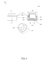
- FIG. 4 shows the ultrasound transducer cartridge 112 in a side view, a perspective view and in a cross-sectional view.
- a cartridge housing 134 is mounted with a piezoelectric element 136 on an inside of the cartridge housing as shown.
- the cartridge housing 134 is provided with a matching layer 144 with a thickness 138 in the part of the cartridge housing 134 where the piezoelectric element is mounted.
- the cartridge 112 has the diameter 130 in the part 132.
- the figure shows the bearing surface 142 of the transducer cartridge which surface is provided for mounting the sealing means 114 (shown in FIG. 2 and 3 ).
- the sealing means 114 has a rectangular cross-section.
- the rectangular cross-section is fitted to the substantially plane surfaces 116 and 142.
- the rectangular cross-section of the sealing means when seen perpendicular to a sealing surface, may also be a reason for referring to the sealing means as a gasket and i.e. in the shown embodiments not an O-ring having a circular cross section.
- sealing means 114 which are useable for the purpose of providing a fluid tight consumption ultrasound flow meter are shown in FIG. 5.1-5.3 .
- FIG. 5.1 shows a cross-section of a sealing means 114 with a through going hole 502 in the middle of the sealing, for receiving the transducer cartridge, and where sealing surfaces are provided with one or more slightly concave sealing surfaces 504, in the example two concave surfaces are shown.
- FIG. 5.2 shows a sealing means 114 with a sealing surface which is provided with one or more slightly convex sealing surfaces 506, in the example two convex surfaces are provided, one on each side of the sealing means 114.
- FIG. 5.3 shows a combination sealing means having at least one side as shown with sealing portions 508 with a substantially rectangular shape or cross-section and portion which are rounded 510, i.e. convex or concave.
- the sealing means disclosed herein has a sealing surface which seen in a cross-section, has at least a portion which is slightly concave, slightly convex, substantially flat 508, substantially plane, square 508 or rectangular.
- the described sealing means are envisaged to be positioned between and bridging the substantially plane mounting surface 116 of the flow duct and the substantially plane bearing surface 142 of the cartridge.
- at least a main part of the sealing means 114 is provided between the two surfaces 142 and 116 and possibly a minor indentation is provided in one or both of the surfaces 116, 142.
- an ultrasound transducer with a flow duct 104 comprising one or more mounting holes 110 for mounting one or more transducer cartridges 112, and one or more transducer cartridges arranged in the one or more mounting holes, and where the flow duct is provided with a mounting surface 116 at each of one or more of the mounting holes, and the mounting surface is dimensioned to receive a transducer cartridge, and the transducer cartridge is mountable on the mounting surface so as to use the pressure within the flow duct for pressing the transducer cartridge towards the sealing means, a sealing means 114 hereby being pressed towards the mounting surface.
Landscapes
- Physics & Mathematics (AREA)
- Measuring Volume Flow (AREA)
- Electromagnetism (AREA)
- Fluid Mechanics (AREA)
- General Physics & Mathematics (AREA)
Abstract
Description
- The invention relates to an ultrasound flow meter and in particular to an ultrasound flow meter with a transducer cartridge mounting surface.
- Ultrasound flow meters for ultrasonic measurement of fluid flow are e.g. used for measuring the flow of gases and liquids, and in particular liquids such as water.
- In some applications the flow meters are used for relatively hot fluids under a relatively high pressure. The temperature of the fluids may be in an area of until 150-180°C and under typical working conditions the pressure in the fluid is typically 4-8*105 Pa. Though, pressure bursts may occur which provides a pressure of more than 100*105 Pa in an ultrasound flow meter mounted in a piping system, i.e. pressure bursts with a pressure ranging from the pressure under typical working conditions and to a pressure in the fluid of more than 100*105 Pa (100 bar) may occur. Similarly the temperature may vary from 0°C to the temperature area of until 150-180°C.
- In piping systems an important issue is fluid tightness of the system under all present conditions. Furthermore it is of outmost importance for a piping system including an ultrasound flow meter that the system and hereby the ultrasound flow meter continues to be fluid tight, year after year. A flow meter which leaks and therefore must be repaired or exchanged is highly disadvantageous. Furthermore, a piping system leaking a fluid with a temperature well above 100°C may become dangerous to any person present near the piping system.
These needs must be fulfilled while also considering factors such as production and assembling cost of the flow meter. - Flow meters known to the present inventor fail to some extent to provide one or more of these needs possibly while also considering one or more of the described or other factors. The inventor of the present invention has therefore appreciated that an improved ultrasound flow meter is of benefit, and has in consequence devised the present invention.
- It may be seen as an object of the present invention to provide an improved flow meter for ultrasonic measurement of fluid flow. Preferably, the invention alleviates, mitigates or eliminates one or more of the above or other disadvantages singly or in any combination.
- The present invention provides this in accordance with the present main claim.
- When an ultrasound flow meter is provided in accordance with the claims and in particular when a flow duct of the ultrasound flow meter is provided with a mounting surface at each of one or more ultrasound transducer mounting holes, and the mounting surface is dimensioned to receive a transducer cartridge, and the transducer cartridge is mounted on the mounting surface so as to use the pressure within the flow duct for pressing the transducer cartridge towards the sealing means, the sealing means hereby being pressed towards the mounting surface, a possible advantage may be that an ultrasound transducer which is more resistant to high temperatures and/or high pressures and/or changing temperature and/or changing pressure without leaking is provided. Possibly an advantage hereby may alternatively or additionally be that it may be prevented to use a rather flexible sealing means, such as a relatively soft rubber O-ring, when sealing the ultrasound cartridge towards the flow duct. While hereby still or also being able to provide a fluid tight flow duct which is fluid tight under high and/or varying pressures and/or under relatively high and/or changing temperatures year after year. Especially, when the flow meter is as described herein and the transducer cartridge is pre-stressed towards the sealing between the transducer cartridge and the mounting surface with a surface pressure on the sealing means of at least 2 MPa, a possible advantage is that a consumption flow meter which is more resistant to high temperatures and/or high pressures and/or changing temperature and/or changing pressure without leaking is provided.
- When the flow duct and the one or more mounting surfaces at the one or more mounting holes are provided in one monolithic duct element, a possible advantage is that a number of possible leaking connections are reduced.
- When the transducer cartridge is mountable from an inside of the flow duct on the mounting surface, a possible advantage is that in this way the need for providing the cartridge in a plurality of parts to be connected with each other upon mounting the cartridge is prevented. Though, it is still a possibility to provide the transducer cartridge in two parts - one part which is mounted from an outside of the flow duct and one part such as a nut member which is attached to the transducer cartridge from an inside of the flow duct. Either way the one or more transducer cartridges are connectable to the flow duct so as to form part of a fluid tight flow duct.
- In accordance with a second aspect of the invention there is provided a method of providing a fluid tight consumption flow meter, the flow meter comprising
- a flow duct with a fluid inlet and a fluid outlet, a flow of fluid within the flow duct creating a pressure within the flow duct, the flow duct furthermore comprising one or more mounting holes for mounting one or more transducer cartridges,
- one or more transducer cartridges arranged in the one or more mounting holes so as to enable a measurement of the fluid flow from the inlet to the outlet in the flow duct,
- a sealing means provided in the one or more mounting holes, where the flow duct is provided with a mounting surface at each of one or more of the mounting holes, and the method comprises
- mounting the sealing means on the mounting surface or on a bearing surface of the transducer cartridge,
- mounting the transducer cartridge so as to use any pressure within the flow duct for pressing the transducer cartridge towards the sealing means, the sealing means hereby being pressed towards the mounting surface, and
- pre-stressing the transducer cartridge towards the sealing means and the mounting surface with a sealing surface pressure on the sealing means of at least 2 MPa.
- In general by writing that 'it is an advantage' by the present invention and referring to an advantage, it must be understood that this advantage may be seen as a possible advantage provided by the invention, but it may also be understood that the invention is particularly, but not exclusively, advantageous for obtaining the described advantage.
- In general the various aspects and advantages of the invention may be combined and coupled in any way possible within the scope of the invention.
- These and other aspects, features and/or advantages of the invention will be apparent from and elucidated with reference to the embodiments described hereinafter.
- Embodiments of the invention will be described, by way of example only, with reference to the drawings, in which
-
FIG. 1 is a perspective 3D view of an ultrasound flow meter, -
FIG. 2 is a cross-section of the ultrasound flow meter, -
FIG. 3 is a cross-section of an ultrasound transducer cartridge mounted in a flow duct element, and -
FIG. 4 shows an ultrasound transducer cartridge and a cross-section thereof. -
FIG. 5.1-5.3 illustrate possible forms of the sealing means usable for the purpose of providing a fluid tight consumption ultrasound flow meter. - An embodiment of the invention is illustrated in
FIG. 1 - 3 . InFIG. 1 aultrasound flow meter 102 for ultrasonic measurement of fluid flow with aflow duct 104 with afluid inlet 106 and afluid outlet 108 is shown. A flow of fluid within the flow duct creates a pressure within the flow duct. As seen inFIG. 2 the flow duct furthermore comprises one ormore mounting holes 110, in the present embodiment two mounting holes, each hole is for mounting anultrasound transducer cartridge 112. The ultrasound cartridges are arranged in the mounting holes so as to enable a measurement of the fluid flow from the inlet to the outlet in the flow duct. Furthermore the ultrasound flow meter is provided with asealing means 114 provided in each of the mounting holes and the flow duct is provided with amounting surface 116 at each of the mounting holes. - The
mounting surface 116, which may alternatively be called a recess on an inside of the mounting hole, is dimensioned to receive a transducer cartridge, and the transducer cartridge is mounted on the mounting surface so as to use the pressure within the flow duct for pressing the transducer cartridge toward the sealing means, the sealing means hereby being pressed towards the mounting surface. It can be seen that, in the present embodiment this is provided in that at least a part of theultrasound transducer cartridge 112 has adimension 130 which is larger than at least a part of adimension 128 of themounting hole 110. In the present embodiment the cartridge has alarger diameter 130 in apart 132 of the cartridge than thediameter 128 of themounting hole 110. - From
FIG. 2 and3 it is shown that the mounting surface is provided inside the flow duct and furthermore that the transducer cartridge is mounted on an inside of the flow duct on the mounting surface. It follows fromFIG. 1 and2 that the flow duct and the mounting surfaces at the mounting holes are provided in onemonolithic duct element 118. Particularly it can be seen that the transducer cartridge is mountable, and in the embodiment shown mounted, from aninside 120 of the flow duct on themounting surface 116. - The transducer cartridges are connected to the flow duct in order to form part of a fluid tight flow duct.
- In
FIG. 3 the sealing means 114 provided between thetransducer cartridge 112 and the mounting surface is shown in detail. The sealing is made from a heat resistant fibre material. Alternatively the sealing material can be made from a relatively hard heat resistant rubber material or from a metal such as copper.
The sealing means may be made from a hard material. The hardness of the sealing material is preferably adapted so that a compression of the sealing, when the sealing is provided between the transducer cartridge and the mounting surface, and when the transducer cartridge is biased or pre-stressed towards the mounting surface, is between approximately 0.1% and less than 10% of a material thickness of the sealing. The compression is preferably in the interval between 2 and 5% of the material thickness of the sealing. The lower limit is primarily provided in order for the sealing to adapt to a roughness and/or minor differences in a slope of the mountingsurface 116 and abearing surface 142. - When the hardness and the pre-stressing etc of the sealing and the construction of the flow meter is as described, it is envisaged that the sealing seals against fluid leaking from this consumption
ultrasound flow meter 102. Any usable acoustic decoupling of ultrasound frequencies, i.e. frequencies larger than 20 kHz, if at all needed, between the transducer and the flow meter housing is preferably provided elsewhere than in the sealing 114, such as electronically. - A consumption meter is a precision instrument normally used to bill a customer consuming a measured flow of fluid, such as in a flow of water in a ultrasound water flow meter.
- From
figure 3 it also follows that the transducer cartridge is partly pre-stressed towards the mounting surface by a flexible retention means 122. The retention means is as shown in the embodiment be mounted from outside the flow duct. In the shown embodiment the retention means is provided as aspring 122. The pre-stressing of the sealing means is i.e. provided by a mechanical construction being assembled and mechanically pre-stressed by assembling the parts and e.g. applying torque to one or more threaded assembling elements. - The sealing has a surface area of the surface towards the mounting
surface 116 or towards the bearingsurface 142. The pre-stressing pressure on the surface area of the sealing is at least 2 MPa, i.e. 2 x 10⁶ Pa, i.e. at least 20 bar. - It can be seen that the sealing means 114 in a sealing area comprising the mounting
surface 116 is a part bridging the flow duct and the transducer cartridge. The mountingsurface 116 of the flow duct and thebearing surface 142 of the cartridge are both substantially plane and it can be seen that the whole of the sealing means is situated between the substantially plane bearingsurface 116 on the transducer cartridge and the substantially plane mountingsurface 142 on the flow duct. Alternatively at least a main part of the sealing is provided between the twosurfaces - It follows from the figure and the description herein that any pressure in the fluid will, if at all possible, press the transducer cartridge even more tightly towards the sealing means 114. Any fluid pressure, and especially fluid pressure bursts, in the fluid will at least not provide a pressure on a complete surface of the transducer cartridge towards the fluid possibly making the transducer cartridge move away from is mounting
surface 116. It follows from the figures that the transducer cartridge is not directly locked to theduct element 118 in thedirection 140 of the fluid pressure. On the contrary, it follows that the transducer cartridge is able to increase the pressure on the sealing means when any increased fluid pressure is provided in the flow duct. - When the necessary torque is applied to the nut of the
transducer cartridge 112, in order to create the pre-stressing surface pressure of at least 2 MPa on the sealing surface, the flexible retention means, orspring 122, will be forced down from what is shown or even be completely flush with an outer surface of the duct element. -
FIG. 4 shows theultrasound transducer cartridge 112 in a side view, a perspective view and in a cross-sectional view. In the figure acartridge housing 134 is mounted with apiezoelectric element 136 on an inside of the cartridge housing as shown. Thecartridge housing 134 is provided with amatching layer 144 with athickness 138 in the part of thecartridge housing 134 where the piezoelectric element is mounted. A direction of the compression stress given by a pressure of a fluid, when the ultrasound cartridge is mounted as part of a fluid tight flow duct, is shown with thearrows 140. In the figure thecartridge 112 has thediameter 130 in thepart 132. The figure shows the bearingsurface 142 of the transducer cartridge which surface is provided for mounting the sealing means 114 (shown inFIG. 2 and3 ). - It follows from the figures that the sealing means 114 has a rectangular cross-section. The rectangular cross-section is fitted to the substantially plane
surfaces - Other possible forms of the sealing means 114 which are useable for the purpose of providing a fluid tight consumption ultrasound flow meter are shown in
FIG. 5.1-5.3 . -
FIG. 5.1 shows a cross-section of a sealing means 114 with a through goinghole 502 in the middle of the sealing, for receiving the transducer cartridge, and where sealing surfaces are provided with one or more slightly concave sealing surfaces 504, in the example two concave surfaces are shown. -
FIG. 5.2 shows a sealing means 114 with a sealing surface which is provided with one or more slightly convex sealing surfaces 506, in the example two convex surfaces are provided, one on each side of the sealing means 114. -
FIG. 5.3 shows a combination sealing means having at least one side as shown with sealingportions 508 with a substantially rectangular shape or cross-section and portion which are rounded 510, i.e. convex or concave. Generally the sealing means disclosed herein has a sealing surface which seen in a cross-section, has at least a portion which is slightly concave, slightly convex, substantially flat 508, substantially plane, square 508 or rectangular. - The described sealing means are envisaged to be positioned between and bridging the substantially plane mounting
surface 116 of the flow duct and the substantially plane bearingsurface 142 of the cartridge. Alternatively at least a main part of the sealing means 114 is provided between the twosurfaces surfaces - Although the present invention has been described in connection with preferred embodiments, it is not intended to be limited to the specific form set forth herein. Rather, the scope of the present invention is limited only by the accompanying claims.
- In this section, certain specific details of the disclosed embodiment are set forth for purposes of explanation rather than limitation, so as to provide a clear and thorough understanding of the present invention. However, it should be understood readily by those skilled in this art, that the present invention may be practised in other embodiments which do not conform exactly to the details set forth herein, without departing significantly from the spirit and scope of this disclosure. Further, in this context, and for the purposes of brevity and clarity, detailed descriptions of well-known apparatus, circuits and methodology have been omitted so as to avoid unnecessary detail and possible confusion.
- In the claims, the term "comprising" does not exclude the presence of other elements or steps. Additionally, although individual features may be included in different claims, these may possibly be advantageously combined, and the inclusion in different claims does not imply that a combination of features is not feasible and/or advantageous. In addition, singular references do not exclude a plurality. Thus, references to "a", "an", "first", "second" etc. do not preclude a plurality. Reference signs are included in the claims however the inclusion of the reference signs is only for clarity reasons and should not be construed as limiting the scope of the claims.
- In summary it is herein disclosed that in order e.g. to provide an ultrasound flow meter which is more resistant to high temperatures and/or changing temperature without leaking there is provided an ultrasound transducer with a
flow duct 104 comprising one or more mountingholes 110 for mounting one ormore transducer cartridges 112, and one or more transducer cartridges arranged in the one or more mounting holes, and where the flow duct is provided with a mountingsurface 116 at each of one or more of the mounting holes, and the mounting surface is dimensioned to receive a transducer cartridge, and the transducer cartridge is mountable on the mounting surface so as to use the pressure within the flow duct for pressing the transducer cartridge towards the sealing means, a sealing means 114 hereby being pressed towards the mounting surface.
Claims (15)
- An ultrasound flow meter (102) for ultrasonic measurement of fluid flow, the ultrasound flow meter comprisinga flow duct (104) with a fluid inlet (106) and a fluid outlet (108), a flow of fluid within the flow duct creating a pressure within the flow duct, the flow duct furthermore comprising one or more mounting holes (110) for mounting one or more transducer cartridges (112),
one or more transducer cartridges arranged in the one or more mounting holes so as to enable a measurement of the fluid flow from the inlet to the outlet in the flow duct,
a sealing means (114) provided in the one or more mounting holes, and whereinthe flow duct is provided with a mounting surface (116) at each of one or more of the mounting holes, and
the mounting surface is dimensioned to receive a transducer cartridge, and
the transducer cartridge is mountable on the mounting surface so as to use the pressure within the flow duct for pressing the transducer cartridge towards the sealing means (114), the sealing means hereby being pressed towards the mounting surface, and wherein the transducer cartridge is pre-stressed towards the sealing between the transducer cartridge and the mounting surface with a surface pressure on the sealing means of at least 2 MPa. - An ultrasound flow meter according to claim 1, wherein the mounting surface is provided inside the flow duct.
- An ultrasound flow meter according to any of the preceding claims, wherein the transducer cartridge is mounted on an inside of the flow duct on the mounting surface.
- An ultrasound flow meter according to any of the preceding claims, wherein the flow duct and the one or more mounting surfaces at the one or more mounting holes are provided in one monolithic duct element (118).
- An ultrasound flow meter according to any of the preceding claims, wherein the transducer cartridge is mountable from an inside (120) of the flow duct on the mounting surface (116).
- An ultrasound flow meter according to any of the preceding claims, wherein the one or more transducer cartridges are connected to the flow duct so as to form part of a fluid tight flow duct.
- An ultrasound flow meter according to any of the preceding claims, wherein the sealing means (114) is made from a hard material.
- An ultrasound flow meter according to any of the preceding claims, wherein the sealing means (114) is having a hardness adapted to be compressed in the interval from 0,1% to 10%, when the transducer cartridge is pre-stressed towards the sealing surface.
- An ultrasound flow meter according to any of the preceding claims, wherein the sealing means (114) is having a hardness adapted to be compressed in the interval from 2% to 5%, when the transducer cartridge is pre-stressed towards the sealing surface.
- An ultrasound flow meter according to any of the preceding claims, wherein the sealing means (114) is made from a heat resistant fibre material.
- An ultrasound flow meter according to any of the preceding claims, wherein the sealing means (114) in a sealing area is a part bridging the flow duct (104) and the transducer cartridge (112).
- An ultrasound flow meter according to any of the preceding claims, wherein a main part of the sealing means (114) is situated between a substantially plane surface (142) on the transducer cartridge (112) and a substantially plane mounting surface (116) on the flow duct (104).
- An ultrasound flow meter according to any of the preceding claims, wherein a sealing between the flow duct (104) and the one or more transducer cartridges (112) only consist of a sealing type as described in claims 1-12.
- An ultrasound flow meter according to any of the preceding claims, wherein the sealing means (114) has a sealing surface which has at least a portion which is comprised in a group of non-circular cross-sections, such as slightly concave, slightly convex, substantially flat, substantially plane, square or rectangular.
- A method of providing a fluid tight consumption flow meter, the flow meter comprising- a flow duct (104) with a fluid inlet (106) and a fluid outlet (108), a flow of fluid within the flow duct creating a pressure within the flow duct, the flow duct furthermore comprising one or more mounting holes (110) for mounting one or more transducer cartridges (112),- one or more transducer cartridges arranged in the one or more mounting holes so as to enable a measurement of the fluid flow from the inlet to the outlet in the flow duct,- a sealing means (114) provided in the one or more mounting holes, where the flow duct is provided with a mounting surface (116) at each of one or more of the mounting holes, and the method comprises- mounting the sealing means on the mounting surface (116) or on a bearing surface (142) of the transducer cartridge,- mounting the transducer cartridge (112) so as to use any pressure within the flow duct for pressing the transducer cartridge towards the sealing means, the sealing means hereby being pressed towards the mounting surface, and- pre-stressing the transducer cartridge towards the sealing means and the mounting surface with a sealing surface pressure on the sealing means of at least 2 MPa.
Priority Applications (1)
| Application Number | Priority Date | Filing Date | Title |
|---|---|---|---|
| EP09161190A EP2141463B1 (en) | 2008-07-02 | 2009-05-27 | Ultrasound flow meter with transducer cartridge mounting surface and sealing means |
Applications Claiming Priority (2)
| Application Number | Priority Date | Filing Date | Title |
|---|---|---|---|
| EP08159486 | 2008-07-02 | ||
| EP09161190A EP2141463B1 (en) | 2008-07-02 | 2009-05-27 | Ultrasound flow meter with transducer cartridge mounting surface and sealing means |
Publications (2)
| Publication Number | Publication Date |
|---|---|
| EP2141463A1 true EP2141463A1 (en) | 2010-01-06 |
| EP2141463B1 EP2141463B1 (en) | 2011-02-16 |
Family
ID=40119306
Family Applications (1)
| Application Number | Title | Priority Date | Filing Date |
|---|---|---|---|
| EP09161190A Active EP2141463B1 (en) | 2008-07-02 | 2009-05-27 | Ultrasound flow meter with transducer cartridge mounting surface and sealing means |
Country Status (4)
| Country | Link |
|---|---|
| EP (1) | EP2141463B1 (en) |
| AT (1) | ATE498826T1 (en) |
| DE (1) | DE602009000735D1 (en) |
| DK (1) | DK2141463T3 (en) |
Cited By (2)
| Publication number | Priority date | Publication date | Assignee | Title |
|---|---|---|---|---|
| EP2594907A1 (en) | 2011-11-21 | 2013-05-22 | Kamstrup A/S | Flow meter with reinforced polymer house |
| CN108871477A (en) * | 2018-06-05 | 2018-11-23 | 北京华水仪表系统有限公司 | Ultrasonic open channel flowmeter |
Families Citing this family (1)
| Publication number | Priority date | Publication date | Assignee | Title |
|---|---|---|---|---|
| US10557732B2 (en) * | 2017-12-07 | 2020-02-11 | Cameron International Corporation | Flowmeters and methods of manufacture |
Citations (4)
| Publication number | Priority date | Publication date | Assignee | Title |
|---|---|---|---|---|
| US5515733A (en) | 1991-03-18 | 1996-05-14 | Panametrics, Inc. | Ultrasonic transducer system with crosstalk isolation |
| DE4443415A1 (en) | 1994-12-06 | 1996-06-13 | Siemens Ag | Device for receiving a sound transducer and ultrasonic flow meter with the same |
| US20030097879A1 (en) | 2001-11-28 | 2003-05-29 | Van Klooster Jeroen Martin | Flowmeter |
| US6647804B1 (en) | 1999-02-10 | 2003-11-18 | Rd Instruments, Inc. | System and method for flow measurement in a pipe |
-
2009
- 2009-05-27 AT AT09161190T patent/ATE498826T1/en not_active IP Right Cessation
- 2009-05-27 DE DE602009000735T patent/DE602009000735D1/en active Active
- 2009-05-27 EP EP09161190A patent/EP2141463B1/en active Active
- 2009-05-27 DK DK09161190.5T patent/DK2141463T3/en active
Patent Citations (4)
| Publication number | Priority date | Publication date | Assignee | Title |
|---|---|---|---|---|
| US5515733A (en) | 1991-03-18 | 1996-05-14 | Panametrics, Inc. | Ultrasonic transducer system with crosstalk isolation |
| DE4443415A1 (en) | 1994-12-06 | 1996-06-13 | Siemens Ag | Device for receiving a sound transducer and ultrasonic flow meter with the same |
| US6647804B1 (en) | 1999-02-10 | 2003-11-18 | Rd Instruments, Inc. | System and method for flow measurement in a pipe |
| US20030097879A1 (en) | 2001-11-28 | 2003-05-29 | Van Klooster Jeroen Martin | Flowmeter |
Cited By (2)
| Publication number | Priority date | Publication date | Assignee | Title |
|---|---|---|---|---|
| EP2594907A1 (en) | 2011-11-21 | 2013-05-22 | Kamstrup A/S | Flow meter with reinforced polymer house |
| CN108871477A (en) * | 2018-06-05 | 2018-11-23 | 北京华水仪表系统有限公司 | Ultrasonic open channel flowmeter |
Also Published As
| Publication number | Publication date |
|---|---|
| EP2141463B1 (en) | 2011-02-16 |
| DK2141463T3 (en) | 2011-04-18 |
| ATE498826T1 (en) | 2011-03-15 |
| DE602009000735D1 (en) | 2011-03-31 |
Similar Documents
| Publication | Publication Date | Title |
|---|---|---|
| CN102159859B (en) | Comb double-sided stacked gasket for sealing removable flange joints | |
| RU2009138434A (en) | METHOD AND DEVICE FOR TESTING PIPES | |
| KR101630128B1 (en) | Differential pressure sensor and method for manufacturing differential pressure sensor | |
| EP2141463A1 (en) | Ultrasound flow meter with transducer cartridge mounting surface and sealing means | |
| CN103842789A (en) | Retrievable pressure sensor | |
| US10281352B2 (en) | Diaphragm seal and pressure sensor having a diaphragm seal | |
| CN112105901A (en) | Pressure transducer, system and method | |
| JP6054568B1 (en) | Partial pressurizer | |
| JPWO2005029912A1 (en) | Ultrasonic flowmeter using ultrasonic transducer | |
| EP3619512A1 (en) | Overpressure protection system | |
| CN102890115B (en) | control valve monitoring system | |
| JP5175087B2 (en) | Apparatus and method for measuring pressure | |
| US8474474B2 (en) | Control valve having pressure boundary integrity diagnostic capabilities, method of making the control valve, and method of using the control valve | |
| US20180238722A1 (en) | Through-flow Measurement Arrangement and Measuring Transducer for Process Instrumentation Having the Through-flow Measurement Arrangement | |
| US7231831B1 (en) | Manifold valve and pressure transducer assembly | |
| EP1571379A1 (en) | Sealing assembly | |
| US8602459B2 (en) | Refrigeration system connection fitting | |
| US9625068B2 (en) | System and method of a flange seal ring | |
| KR20090080884A (en) | Diaphragm pressure sensor | |
| JP7090017B2 (en) | gasket | |
| KR102723981B1 (en) | Straight Flow Meter Sensor | |
| JP2013019445A (en) | Method and device for indicating amount of packing pressure in joint | |
| CN113790882A (en) | Pressure test device of sealing member | |
| RU120221U1 (en) | MEMBRANE PRESSURE SENSOR - DDM | |
| CN214893830U (en) | A pressure gauge with an adapter |
Legal Events
| Date | Code | Title | Description |
|---|---|---|---|
| PUAI | Public reference made under article 153(3) epc to a published international application that has entered the european phase |
Free format text: ORIGINAL CODE: 0009012 |
|
| AK | Designated contracting states |
Kind code of ref document: A1 Designated state(s): AT BE BG CH CY CZ DE DK EE ES FI FR GB GR HR HU IE IS IT LI LT LU LV MC MK MT NL NO PL PT RO SE SI SK TR |
|
| 17P | Request for examination filed |
Effective date: 20100706 |
|
| GRAP | Despatch of communication of intention to grant a patent |
Free format text: ORIGINAL CODE: EPIDOSNIGR1 |
|
| GRAS | Grant fee paid |
Free format text: ORIGINAL CODE: EPIDOSNIGR3 |
|
| GRAA | (expected) grant |
Free format text: ORIGINAL CODE: 0009210 |
|
| AK | Designated contracting states |
Kind code of ref document: B1 Designated state(s): AT BE BG CH CY CZ DE DK EE ES FI FR GB GR HR HU IE IS IT LI LT LU LV MC MK MT NL NO PL PT RO SE SI SK TR |
|
| REG | Reference to a national code |
Ref country code: GB Ref legal event code: FG4D |
|
| REG | Reference to a national code |
Ref country code: CH Ref legal event code: EP |
|
| REG | Reference to a national code |
Ref country code: IE Ref legal event code: FG4D |
|
| REF | Corresponds to: |
Ref document number: 602009000735 Country of ref document: DE Date of ref document: 20110331 Kind code of ref document: P |
|
| REG | Reference to a national code |
Ref country code: DE Ref legal event code: R096 Ref document number: 602009000735 Country of ref document: DE Effective date: 20110331 |
|
| REG | Reference to a national code |
Ref country code: DK Ref legal event code: T3 |
|
| REG | Reference to a national code |
Ref country code: NL Ref legal event code: VDEP Effective date: 20110216 |
|
| LTIE | Lt: invalidation of european patent or patent extension |
Effective date: 20110216 |
|
| PG25 | Lapsed in a contracting state [announced via postgrant information from national office to epo] |
Ref country code: LT Free format text: LAPSE BECAUSE OF FAILURE TO SUBMIT A TRANSLATION OF THE DESCRIPTION OR TO PAY THE FEE WITHIN THE PRESCRIBED TIME-LIMIT Effective date: 20110216 Ref country code: ES Free format text: LAPSE BECAUSE OF FAILURE TO SUBMIT A TRANSLATION OF THE DESCRIPTION OR TO PAY THE FEE WITHIN THE PRESCRIBED TIME-LIMIT Effective date: 20110527 Ref country code: SE Free format text: LAPSE BECAUSE OF FAILURE TO SUBMIT A TRANSLATION OF THE DESCRIPTION OR TO PAY THE FEE WITHIN THE PRESCRIBED TIME-LIMIT Effective date: 20110216 Ref country code: PT Free format text: LAPSE BECAUSE OF FAILURE TO SUBMIT A TRANSLATION OF THE DESCRIPTION OR TO PAY THE FEE WITHIN THE PRESCRIBED TIME-LIMIT Effective date: 20110616 Ref country code: HR Free format text: LAPSE BECAUSE OF FAILURE TO SUBMIT A TRANSLATION OF THE DESCRIPTION OR TO PAY THE FEE WITHIN THE PRESCRIBED TIME-LIMIT Effective date: 20110216 Ref country code: NO Free format text: LAPSE BECAUSE OF FAILURE TO SUBMIT A TRANSLATION OF THE DESCRIPTION OR TO PAY THE FEE WITHIN THE PRESCRIBED TIME-LIMIT Effective date: 20110516 Ref country code: LV Free format text: LAPSE BECAUSE OF FAILURE TO SUBMIT A TRANSLATION OF THE DESCRIPTION OR TO PAY THE FEE WITHIN THE PRESCRIBED TIME-LIMIT Effective date: 20110216 Ref country code: GR Free format text: LAPSE BECAUSE OF FAILURE TO SUBMIT A TRANSLATION OF THE DESCRIPTION OR TO PAY THE FEE WITHIN THE PRESCRIBED TIME-LIMIT Effective date: 20110517 |
|
| PG25 | Lapsed in a contracting state [announced via postgrant information from national office to epo] |
Ref country code: FI Free format text: LAPSE BECAUSE OF FAILURE TO SUBMIT A TRANSLATION OF THE DESCRIPTION OR TO PAY THE FEE WITHIN THE PRESCRIBED TIME-LIMIT Effective date: 20110216 Ref country code: PL Free format text: LAPSE BECAUSE OF FAILURE TO SUBMIT A TRANSLATION OF THE DESCRIPTION OR TO PAY THE FEE WITHIN THE PRESCRIBED TIME-LIMIT Effective date: 20110216 Ref country code: BG Free format text: LAPSE BECAUSE OF FAILURE TO SUBMIT A TRANSLATION OF THE DESCRIPTION OR TO PAY THE FEE WITHIN THE PRESCRIBED TIME-LIMIT Effective date: 20110516 Ref country code: SI Free format text: LAPSE BECAUSE OF FAILURE TO SUBMIT A TRANSLATION OF THE DESCRIPTION OR TO PAY THE FEE WITHIN THE PRESCRIBED TIME-LIMIT Effective date: 20110216 Ref country code: NL Free format text: LAPSE BECAUSE OF FAILURE TO SUBMIT A TRANSLATION OF THE DESCRIPTION OR TO PAY THE FEE WITHIN THE PRESCRIBED TIME-LIMIT Effective date: 20110216 Ref country code: CY Free format text: LAPSE BECAUSE OF FAILURE TO SUBMIT A TRANSLATION OF THE DESCRIPTION OR TO PAY THE FEE WITHIN THE PRESCRIBED TIME-LIMIT Effective date: 20110216 Ref country code: AT Free format text: LAPSE BECAUSE OF FAILURE TO SUBMIT A TRANSLATION OF THE DESCRIPTION OR TO PAY THE FEE WITHIN THE PRESCRIBED TIME-LIMIT Effective date: 20110216 Ref country code: BE Free format text: LAPSE BECAUSE OF FAILURE TO SUBMIT A TRANSLATION OF THE DESCRIPTION OR TO PAY THE FEE WITHIN THE PRESCRIBED TIME-LIMIT Effective date: 20110216 |
|
| PG25 | Lapsed in a contracting state [announced via postgrant information from national office to epo] |
Ref country code: EE Free format text: LAPSE BECAUSE OF FAILURE TO SUBMIT A TRANSLATION OF THE DESCRIPTION OR TO PAY THE FEE WITHIN THE PRESCRIBED TIME-LIMIT Effective date: 20110216 |
|
| PG25 | Lapsed in a contracting state [announced via postgrant information from national office to epo] |
Ref country code: RO Free format text: LAPSE BECAUSE OF FAILURE TO SUBMIT A TRANSLATION OF THE DESCRIPTION OR TO PAY THE FEE WITHIN THE PRESCRIBED TIME-LIMIT Effective date: 20110216 Ref country code: SK Free format text: LAPSE BECAUSE OF FAILURE TO SUBMIT A TRANSLATION OF THE DESCRIPTION OR TO PAY THE FEE WITHIN THE PRESCRIBED TIME-LIMIT Effective date: 20110216 Ref country code: CZ Free format text: LAPSE BECAUSE OF FAILURE TO SUBMIT A TRANSLATION OF THE DESCRIPTION OR TO PAY THE FEE WITHIN THE PRESCRIBED TIME-LIMIT Effective date: 20110216 |
|
| PLBE | No opposition filed within time limit |
Free format text: ORIGINAL CODE: 0009261 |
|
| STAA | Information on the status of an ep patent application or granted ep patent |
Free format text: STATUS: NO OPPOSITION FILED WITHIN TIME LIMIT |
|
| PG25 | Lapsed in a contracting state [announced via postgrant information from national office to epo] |
Ref country code: MT Free format text: LAPSE BECAUSE OF FAILURE TO SUBMIT A TRANSLATION OF THE DESCRIPTION OR TO PAY THE FEE WITHIN THE PRESCRIBED TIME-LIMIT Effective date: 20110216 Ref country code: MC Free format text: LAPSE BECAUSE OF NON-PAYMENT OF DUE FEES Effective date: 20110531 |
|
| 26N | No opposition filed |
Effective date: 20111117 |
|
| REG | Reference to a national code |
Ref country code: IE Ref legal event code: MM4A |
|
| REG | Reference to a national code |
Ref country code: DE Ref legal event code: R097 Ref document number: 602009000735 Country of ref document: DE Effective date: 20111117 |
|
| PG25 | Lapsed in a contracting state [announced via postgrant information from national office to epo] |
Ref country code: IE Free format text: LAPSE BECAUSE OF NON-PAYMENT OF DUE FEES Effective date: 20110527 |
|
| PG25 | Lapsed in a contracting state [announced via postgrant information from national office to epo] |
Ref country code: IT Free format text: LAPSE BECAUSE OF FAILURE TO SUBMIT A TRANSLATION OF THE DESCRIPTION OR TO PAY THE FEE WITHIN THE PRESCRIBED TIME-LIMIT Effective date: 20110216 |
|
| PG25 | Lapsed in a contracting state [announced via postgrant information from national office to epo] |
Ref country code: MK Free format text: LAPSE BECAUSE OF FAILURE TO SUBMIT A TRANSLATION OF THE DESCRIPTION OR TO PAY THE FEE WITHIN THE PRESCRIBED TIME-LIMIT Effective date: 20110216 |
|
| PG25 | Lapsed in a contracting state [announced via postgrant information from national office to epo] |
Ref country code: LU Free format text: LAPSE BECAUSE OF NON-PAYMENT OF DUE FEES Effective date: 20110527 |
|
| PG25 | Lapsed in a contracting state [announced via postgrant information from national office to epo] |
Ref country code: IS Free format text: LAPSE BECAUSE OF FAILURE TO SUBMIT A TRANSLATION OF THE DESCRIPTION OR TO PAY THE FEE WITHIN THE PRESCRIBED TIME-LIMIT Effective date: 20110216 |
|
| PG25 | Lapsed in a contracting state [announced via postgrant information from national office to epo] |
Ref country code: TR Free format text: LAPSE BECAUSE OF FAILURE TO SUBMIT A TRANSLATION OF THE DESCRIPTION OR TO PAY THE FEE WITHIN THE PRESCRIBED TIME-LIMIT Effective date: 20110216 |
|
| PG25 | Lapsed in a contracting state [announced via postgrant information from national office to epo] |
Ref country code: HU Free format text: LAPSE BECAUSE OF FAILURE TO SUBMIT A TRANSLATION OF THE DESCRIPTION OR TO PAY THE FEE WITHIN THE PRESCRIBED TIME-LIMIT Effective date: 20110216 |
|
| REG | Reference to a national code |
Ref country code: CH Ref legal event code: PL |
|
| GBPC | Gb: european patent ceased through non-payment of renewal fee |
Effective date: 20130527 |
|
| PG25 | Lapsed in a contracting state [announced via postgrant information from national office to epo] |
Ref country code: LI Free format text: LAPSE BECAUSE OF NON-PAYMENT OF DUE FEES Effective date: 20130531 Ref country code: CH Free format text: LAPSE BECAUSE OF NON-PAYMENT OF DUE FEES Effective date: 20130531 |
|
| PG25 | Lapsed in a contracting state [announced via postgrant information from national office to epo] |
Ref country code: GB Free format text: LAPSE BECAUSE OF NON-PAYMENT OF DUE FEES Effective date: 20130527 |
|
| REG | Reference to a national code |
Ref country code: FR Ref legal event code: PLFP Year of fee payment: 7 |
|
| REG | Reference to a national code |
Ref country code: FR Ref legal event code: PLFP Year of fee payment: 8 |
|
| REG | Reference to a national code |
Ref country code: FR Ref legal event code: PLFP Year of fee payment: 9 |
|
| REG | Reference to a national code |
Ref country code: FR Ref legal event code: PLFP Year of fee payment: 10 |
|
| REG | Reference to a national code |
Ref country code: DE Ref legal event code: R084 Ref document number: 602009000735 Country of ref document: DE |
|
| P01 | Opt-out of the competence of the unified patent court (upc) registered |
Effective date: 20230516 |
|
| PGFP | Annual fee paid to national office [announced via postgrant information from national office to epo] |
Ref country code: DE Payment date: 20250521 Year of fee payment: 17 |
|
| PGFP | Annual fee paid to national office [announced via postgrant information from national office to epo] |
Ref country code: DK Payment date: 20250526 Year of fee payment: 17 |
|
| PGFP | Annual fee paid to national office [announced via postgrant information from national office to epo] |
Ref country code: FR Payment date: 20250528 Year of fee payment: 17 |