EP2141326A2 - Airfoil with tapered radial cooling passage - Google Patents
Airfoil with tapered radial cooling passage Download PDFInfo
- Publication number
- EP2141326A2 EP2141326A2 EP09251018A EP09251018A EP2141326A2 EP 2141326 A2 EP2141326 A2 EP 2141326A2 EP 09251018 A EP09251018 A EP 09251018A EP 09251018 A EP09251018 A EP 09251018A EP 2141326 A2 EP2141326 A2 EP 2141326A2
- Authority
- EP
- European Patent Office
- Prior art keywords
- core
- airfoil
- length
- cooling passage
- width
- Prior art date
- Legal status (The legal status is an assumption and is not a legal conclusion. Google has not performed a legal analysis and makes no representation as to the accuracy of the status listed.)
- Withdrawn
Links
Images

Classifications
-
- F—MECHANICAL ENGINEERING; LIGHTING; HEATING; WEAPONS; BLASTING
- F01—MACHINES OR ENGINES IN GENERAL; ENGINE PLANTS IN GENERAL; STEAM ENGINES
- F01D—NON-POSITIVE DISPLACEMENT MACHINES OR ENGINES, e.g. STEAM TURBINES
- F01D5/00—Blades; Blade-carrying members; Heating, heat-insulating, cooling or antivibration means on the blades or the members
- F01D5/12—Blades
- F01D5/14—Form or construction
- F01D5/18—Hollow blades, i.e. blades with cooling or heating channels or cavities; Heating, heat-insulating or cooling means on blades
- F01D5/187—Convection cooling
-
- F—MECHANICAL ENGINEERING; LIGHTING; HEATING; WEAPONS; BLASTING
- F05—INDEXING SCHEMES RELATING TO ENGINES OR PUMPS IN VARIOUS SUBCLASSES OF CLASSES F01-F04
- F05D—INDEXING SCHEME FOR ASPECTS RELATING TO NON-POSITIVE-DISPLACEMENT MACHINES OR ENGINES, GAS-TURBINES OR JET-PROPULSION PLANTS
- F05D2250/00—Geometry
- F05D2250/20—Three-dimensional
- F05D2250/21—Three-dimensional pyramidal
-
- F—MECHANICAL ENGINEERING; LIGHTING; HEATING; WEAPONS; BLASTING
- F05—INDEXING SCHEMES RELATING TO ENGINES OR PUMPS IN VARIOUS SUBCLASSES OF CLASSES F01-F04
- F05D—INDEXING SCHEME FOR ASPECTS RELATING TO NON-POSITIVE-DISPLACEMENT MACHINES OR ENGINES, GAS-TURBINES OR JET-PROPULSION PLANTS
- F05D2250/00—Geometry
- F05D2250/20—Three-dimensional
- F05D2250/29—Three-dimensional machined; miscellaneous
- F05D2250/292—Three-dimensional machined; miscellaneous tapered
-
- F—MECHANICAL ENGINEERING; LIGHTING; HEATING; WEAPONS; BLASTING
- F05—INDEXING SCHEMES RELATING TO ENGINES OR PUMPS IN VARIOUS SUBCLASSES OF CLASSES F01-F04
- F05D—INDEXING SCHEME FOR ASPECTS RELATING TO NON-POSITIVE-DISPLACEMENT MACHINES OR ENGINES, GAS-TURBINES OR JET-PROPULSION PLANTS
- F05D2300/00—Materials; Properties thereof
- F05D2300/10—Metals, alloys or intermetallic compounds
- F05D2300/13—Refractory metals, i.e. Ti, V, Cr, Zr, Nb, Mo, Hf, Ta, W
Definitions
- This disclosure relates to a supplemental radial cooling passage for an airfoil.
- Turbine blades are utilized in gas turbine engines.
- a turbine blade typically includes a platform having a root on one side and an airfoil extending from the platform opposite the root. The root is secured to a turbine rotor.
- Cooling circuits are formed within the airfoil to circulate cooling fluid, such as air.
- multiple relatively large cooling channels extend radially from the root toward a tip of the airfoil. Air flows through the channels and cools the airfoil, which is relatively hot during operation of the gas turbine engine.
- Some advanced cooling designs use one or more radial cooling passages that extend from the root toward the tip.
- the cooling passages are arranged between the cooling channels and an exterior surface of the airfoil.
- the cooling passages provide extremely high convective cooling.
- the Applicant has discovered that in some cooling designs the airfoil is overcooled at the base of the airfoil near the platform. It is believed that strong secondary flows, particularly on the suction side, force the migration of relatively cool fluid off the end wall and onto the suction side of the blade. This results in relatively low external gas temperatures. Internally, the coolant temperature is relatively cool as it has just entered the blade. The high heat transfer coefficients provided by the cooling passage in this region are undesirable as it causes overcooling of the external surface and premature heating of the coolant air.
- tapeered radial cooling passages have been used.
- the wall adjacent to the suction side exterior surface is tapered as it extends towards the tip. This configuration undesirably results in increased cooling near the platform as compared to near the tip due to the larger convection surface near the platform.
- Mach numbers also remain relatively constant resulting in uniform heat transfer rates within the passage.
- External three-dimensional flows and nonuniform gas temperature profiles cause temperatures and heat transfer rates to be typically lower near the inner and outer radii of the airfoil. This external heat load, combined with the cool coolant fluid near the inlet to the airfoil cause the external surface to be overcooled.
- a turbine engine airfoil that includes an airfoil structure having an exterior surface and an end portion.
- a cooling passage extends a length radially within the structure in a direction toward the end portion.
- the cooling passage provides a convection surface along the length adjacent to the exterior surface.
- the convection surface includes a generally uniform width along the length.
- the cooling passage has generally decreasing cross-sectional areas along the length in the direction. The width and the cross-sectional areas are generally perpendicular to the length.
- the airfoil may extend from a platform and a root may extend from the platform opposite the airfoil.
- the cooling passage is provided by a core structure that extends from a first end to a second end along the length.
- the core structure includes a side having a generally uniform width along the length.
- the core structure includes a first thickness at the first end providing with the width a first area that is greater than a second area, which is provided by the width and a second thickness at the second end. Accordingly, a radial cooling passage provides desired cooling of the airfoil.
- Figure 1 schematically illustrates a gas turbine engine 10 that includes a fan 14, a compressor section 16, a combustion section 18 and a turbine section 11, which are disposed about a central axis 12.
- air compressed in the compressor section 16 is mixed with fuel that is burned in combustion section 18 and expanded in the turbine section 11.
- the turbine section 11 includes, for example, rotors 13 and 15 that, in response to expansion of the burned fuel, rotate, which drives the compressor section 16 and fan 14.
- the turbine section 11 includes alternating rows of blades 20 and static airfoils or vanes 19. It should be understood that Figure 1 is for illustrative purposes only and is in no way intended as a limitation on this disclosure or its application.
- FIG. 2 An example blade 20 is shown in Figure 2 .
- the blade 20 includes a platform 32 supported by a root 36, which is secured to a rotor.
- An airfoil 34 extends radially outwardly from the platform 32 opposite the root 36. While the airfoil 34 is disclosed as being part of a turbine blade 20, it should be understood that the disclosed airfoil can also be used as a vane.
- the airfoil 34 includes an exterior surface 58 extending in a chord-wise direction C from a leading edge 38 to a trailing edge 40.
- the airfoil 34 extends between pressure and suction sides 42, 44 in a airfoil thickness direction T, which is generally perpendicular to the chord-wise direction C.
- the airfoil 34 extends from the platform 32 in a radial direction R to an end portion or tip 33.
- Cooling holes 48 are typically provided on the leading edge 38 and various other locations on the airfoil 34 (not shown).
- multiple, relatively large radial cooling channels 50, 52, 54 are provided internally within the airfoil 34 to deliver airflow for cooling the airfoil.
- the cooling channels 50, 52, 54 typically provide cooling air from the root 36 of the blade 20.
- a radially extending cooling passage 56 is provided in a wall 60 between the exterior surface 58 and the cooling channels 50, 52, 54 at the suction side 44.
- First and second wall portions 68, 70 are provided on either side of the radial cooling passage 56 respectively adjacent to the exterior surface 58 and the cooling channel 52.
- the example cooling passages can be provided at other locations within the airfoil.
- the disclosed cooling passage 56 can also be provided on the pressure side (shown) and leading edge (not shown).
- the radial cooling passages 56 tapers along a length 64 from the platform 32 to the tip 33.
- a width 62 of the radial cooling passage 56 remains generally constant or uniform along the length 64.
- a convection surface 72 that is provided adjacent to the exterior surface 58 remains generally uniform along the length 64.
- the convection surface 72 provides a generally flat surface in one example.
- the convection surface 72 may include heat transfer augmentation features, such as trip strips, pin fins and/or dimples, for example.
- the cross-sectional areas of the radial cooling passage 56 are generally rectangular in shape and may include large fillets at the corners.
- the cooling passage 56 can also be a tapered, round passage.
- Areas A1, A2, A3 along the length 64 respectively include thicknesses 66, 166, 266 that are respectively shown in Figures 4A-4C .
- the thicknesses 66, 166, 266 are substantially less than the width 62.
- the thicknesses 66, 166, 266 and width 62 are substantially less than the length 64.
- the cooling channels 50, 52, 54 are provided by ceramic cores during a casting process, as known.
- the radial cooling passages 56 are provided by a refractory metal core 74 ( Figure 5 ), for example.
- the taper of the core structure 80 can be provided by 3D-rolling, grinding, chemical machining or any other suitable method of reducing the thickness.
- the core structure 80 tapers from a first end 76 to a second end 78 to provide a shape with dimensions corresponding to the radial cooling passages 56.
- a core assembly 81 can be provided in which a portion 86 of the core structure 80 is received in a recess 84 of a ceramic core 82. In this manner, the resultant radial cooling passage 56 provided by the core structure 80 is in fluid communication with a corresponding cooling channel 50, 52, 54 subsequent to the airfoil casting process.
- the reduction in the cross-sectional area increases the Mach number as the coolant moves to the end of the coolant passage.
- the increase in Mach number in turn allows the heat transfer coefficient near the exit of the passage to be higher than near the inlet.
- the heat transfer coefficients in the region of the blade 20 near the platform 32 is reduced. This allows the designer to maintain a uniform value (or adjust to the most desirable value) based upon the product of h*( ⁇ T) resulting in a uniformly cooled blade, where h is the convection heat transfer coefficient and ⁇ T is the temperature gradient.
Landscapes
- Engineering & Computer Science (AREA)
- Mechanical Engineering (AREA)
- General Engineering & Computer Science (AREA)
- Turbine Rotor Nozzle Sealing (AREA)
Abstract
Description
- This disclosure relates to a supplemental radial cooling passage for an airfoil.
- Turbine blades are utilized in gas turbine engines. As known, a turbine blade typically includes a platform having a root on one side and an airfoil extending from the platform opposite the root. The root is secured to a turbine rotor. Cooling circuits are formed within the airfoil to circulate cooling fluid, such as air. Typically, multiple relatively large cooling channels extend radially from the root toward a tip of the airfoil. Air flows through the channels and cools the airfoil, which is relatively hot during operation of the gas turbine engine.
- Some advanced cooling designs use one or more radial cooling passages that extend from the root toward the tip. Typically, the cooling passages are arranged between the cooling channels and an exterior surface of the airfoil. The cooling passages provide extremely high convective cooling.
- The Applicant has discovered that in some cooling designs the airfoil is overcooled at the base of the airfoil near the platform. It is believed that strong secondary flows, particularly on the suction side, force the migration of relatively cool fluid off the end wall and onto the suction side of the blade. This results in relatively low external gas temperatures. Internally, the coolant temperature is relatively cool as it has just entered the blade. The high heat transfer coefficients provided by the cooling passage in this region are undesirable as it causes overcooling of the external surface and premature heating of the coolant air.
- Tapered radial cooling passages have been used. However, in one arrangement, the wall adjacent to the suction side exterior surface is tapered as it extends towards the tip. This configuration undesirably results in increased cooling near the platform as compared to near the tip due to the larger convection surface near the platform.
- In another arrangement in which the cross-sectional area of the cooling passage remains relatively constant cooling fluid, Mach numbers also remain relatively constant resulting in uniform heat transfer rates within the passage. Coolant fluid entering the airfoil at low temperature and increases in temperature as it moves through the cooling passage. External three-dimensional flows and nonuniform gas temperature profiles cause temperatures and heat transfer rates to be typically lower near the inner and outer radii of the airfoil. This external heat load, combined with the cool coolant fluid near the inlet to the airfoil cause the external surface to be overcooled.
- What is needed is a radial cooling passage that provides desired cooling of the airfoil.
- A turbine engine airfoil is disclosed that includes an airfoil structure having an exterior surface and an end portion. A cooling passage extends a length radially within the structure in a direction toward the end portion. The cooling passage provides a convection surface along the length adjacent to the exterior surface. The convection surface includes a generally uniform width along the length. The cooling passage has generally decreasing cross-sectional areas along the length in the direction. The width and the cross-sectional areas are generally perpendicular to the length. The airfoil may extend from a platform and a root may extend from the platform opposite the airfoil.
- The cooling passage is provided by a core structure that extends from a first end to a second end along the length. The core structure includes a side having a generally uniform width along the length. The core structure includes a first thickness at the first end providing with the width a first area that is greater than a second area, which is provided by the width and a second thickness at the second end. Accordingly, a radial cooling passage provides desired cooling of the airfoil.
- These and other features of the disclosure can be best understood from the following specification and drawings, the following of which is a brief description.
-
-
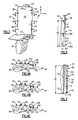
Figure 1 is a schematic of a gas turbine engine incorporating the disclosed airfoil. -
Figure 2 is the airfoil having a tapered radial cooling passage. -
Figure 3 is a cross-sectional view of the airfoil shown inFigure 2 taken along line 3-3. -
Figure 4A is a cross-sectional view of the airfoil shown inFigure 2 taken alongline 4A-4A. -
Figure 4B is a cross-sectional view of the airfoil shown inFigure 2 taken alongline 4B-4B. -
Figure 4C is a cross-sectional view of the airfoil shown inFigure 2 taken alongline 4C-4C. -
Figure 5 is a schematic view of a portion of an example core structure for providing the radial cooling passage. -
Figure 6 is a partial cross-sectional view of a portion of the core structure cooperating with a second core structure, which provides a cooling channel. -
Figure 1 schematically illustrates agas turbine engine 10 that includes afan 14, acompressor section 16, acombustion section 18 and aturbine section 11, which are disposed about acentral axis 12. As known in the art, air compressed in thecompressor section 16 is mixed with fuel that is burned incombustion section 18 and expanded in theturbine section 11. Theturbine section 11 includes, for example,rotors compressor section 16 andfan 14. - The
turbine section 11 includes alternating rows ofblades 20 and static airfoils orvanes 19. It should be understood thatFigure 1 is for illustrative purposes only and is in no way intended as a limitation on this disclosure or its application. - An
example blade 20 is shown inFigure 2 . Theblade 20 includes aplatform 32 supported by aroot 36, which is secured to a rotor. Anairfoil 34 extends radially outwardly from theplatform 32 opposite theroot 36. While theairfoil 34 is disclosed as being part of aturbine blade 20, it should be understood that the disclosed airfoil can also be used as a vane. - The
airfoil 34 includes anexterior surface 58 extending in a chord-wise direction C from a leadingedge 38 to atrailing edge 40. Theairfoil 34 extends between pressure andsuction sides airfoil 34 extends from theplatform 32 in a radial direction R to an end portion or tip 33.Cooling holes 48 are typically provided on the leadingedge 38 and various other locations on the airfoil 34 (not shown). - Referring to
Figures 4A-4C , multiple, relatively largeradial cooling channels airfoil 34 to deliver airflow for cooling the airfoil. Thecooling channels root 36 of theblade 20. - Current advanced cooling designs incorporate supplemental cooling passages arranged between the
exterior surface 58 and one or more of thecooling channels cooling passage 56 is provided in awall 60 between theexterior surface 58 and thecooling channels suction side 44. First andsecond wall portions radial cooling passage 56 respectively adjacent to theexterior surface 58 and thecooling channel 52. However, it should be understood that the example cooling passages can be provided at other locations within the airfoil. For example, the disclosedcooling passage 56 can also be provided on the pressure side (shown) and leading edge (not shown). - As shown in
Figure 3 and Figures 4A-4C , theradial cooling passages 56 tapers along alength 64 from theplatform 32 to the tip 33. Awidth 62 of theradial cooling passage 56 remains generally constant or uniform along thelength 64. As a result, aconvection surface 72 that is provided adjacent to theexterior surface 58 remains generally uniform along thelength 64. Theconvection surface 72 provides a generally flat surface in one example. Theconvection surface 72 may include heat transfer augmentation features, such as trip strips, pin fins and/or dimples, for example. In the example, the cross-sectional areas of theradial cooling passage 56 are generally rectangular in shape and may include large fillets at the corners. Thecooling passage 56 can also be a tapered, round passage. Areas A1, A2, A3 along thelength 64 respectively includethicknesses Figures 4A-4C . Thethicknesses width 62. Thethicknesses width 62 are substantially less than thelength 64. - In one example, the cooling
channels radial cooling passages 56 are provided by a refractory metal core 74 (Figure 5 ), for example. The taper of thecore structure 80 can be provided by 3D-rolling, grinding, chemical machining or any other suitable method of reducing the thickness. Thecore structure 80 tapers from afirst end 76 to asecond end 78 to provide a shape with dimensions corresponding to theradial cooling passages 56. - Referring to
Figure 6 , acore assembly 81 can be provided in which aportion 86 of thecore structure 80 is received in arecess 84 of aceramic core 82. In this manner, the resultantradial cooling passage 56 provided by thecore structure 80 is in fluid communication with acorresponding cooling channel - The reduction in the cross-sectional area increases the Mach number as the coolant moves to the end of the coolant passage. The increase in Mach number in turn allows the heat transfer coefficient near the exit of the passage to be higher than near the inlet. The heat transfer coefficients in the region of the
blade 20 near theplatform 32 is reduced. This allows the designer to maintain a uniform value (or adjust to the most desirable value) based upon the product of h*(ΔT) resulting in a uniformly cooled blade, where h is the convection heat transfer coefficient and ΔT is the temperature gradient. - Although example embodiments have been disclosed, a worker of ordinary skill in this art would recognize that certain modifications would come within the scope of the claims. For that reason, the following claims should be studied to determine their true scope and content.
Claims (15)
- A turbine engine airfoil (34) comprising:an airfoil structure having an exterior surface (58) and an end portion (33), and a cooling passage (56) extending a length (64) radially within the structure in a direction towards the end portion (33), the cooling passage (56) providing a convection surface (72) along the length (64) adjacent to the exterior surface (58), the convection surface (72) including a generally uniform width (62) along the length (64), and the cooling passage (56) having generally decreasing cross-sectional areas (A1, A2, A3) along the length (64) in the direction, the width (62) and the cross-sectional areas (A1, A2, A3) being generally perpendicular to the length (64).
- The turbine engine airfoil according to claim 1, comprising a cooling channel (50, 52, 54) and a wall (60) arranged between the cooling channel (50, 52, 54) and the exterior surface (58) with the cooling passage (56) disposed in the wall (60).
- The turbine engine airfoil according to claim 2, wherein the cooling channel (50, 52, 54) and the cooling passage (56) are in fluid communication with one another.
- The turbine engine airfoil according to claim 2 or 3, wherein the cooling passage (56) separates the wall (60) into first and second wall portions, with the first wall portion arranged between the cooling passage (56) and the exterior surface (58), wherein the exterior surface (58) optionally includes a suction side (44), the convection surface (72) arranged adjacent to the suction side (44).
- The turbine engine airfoil according to any preceding claim, wherein the convection surface (72) is generally flat.
- The turbine engine airfoil according to claim 5, wherein the cross-sectional areas are generally rectangular in shape.
- The turbine engine airfoil according to any preceding claim, wherein the cross-sectional areas (A1, A2, A3) each include a thickness and the width (62), the thickness is substantially less than the width (62), wherein the thicknesses and the width (62) are optionally substantially less than the length (64).
- The turbine engine airfoil according to claim 7, wherein the cooling passage (56) includes first and second ends opposite one another, the second end closer to the end portion than the first end, the cross-sectional areas including first and second areas respectively arranged at the first and second ends and including first and second thicknesses respectively, the first area and first thickness respectively greater than the second area and second thickness.
- A core (74) for manufacturing an airfoil (34) comprising:a core structure (80) extending from a first end (76) to a second end (78) along a length and including a side having a generally uniform width along the length, the structure (80) having a first thickness at the first end providing with the width a first area that is greater than a second area which is provided by the width and a second thickness at the second end.
- The core for manufacturing an airfoil according to claim 9, wherein the side is generally flat.
- The core for manufacturing an airfoil according to claim 10, wherein the first and second areas are generally rectangular in shape.
- The core for manufacturing an airfoil according to claim 9, 10 or 11, wherein the width is substantially greater than either of the first and second thicknesses, and wherein, optionally, the first and second thicknesses are different than one another.
- The core for manufacturing an airfoil according to any of claims 9 to 12, wherein the length is substantially greater than the width and the first and second thicknesses.
- The core for manufacturing an airfoil according to any of claims 9 to 13, wherein the core structure (80) includes a refractory metal material.
- The core for manufacturing an airfoil according to any of claims 9 to 14, comprising a second core (82) cooperating with the core structure (80) and configured to provide fluid communication between passages provided by the second core (82) in the core structure (80) in a cast airfoil, and wherein the core structure (80) and the second core (82) may include different materials than one another.
Applications Claiming Priority (1)
| Application Number | Priority Date | Filing Date | Title |
|---|---|---|---|
| US12/167,435 US8157527B2 (en) | 2008-07-03 | 2008-07-03 | Airfoil with tapered radial cooling passage |
Publications (2)
| Publication Number | Publication Date |
|---|---|
| EP2141326A2 true EP2141326A2 (en) | 2010-01-06 |
| EP2141326A3 EP2141326A3 (en) | 2013-12-25 |
Family
ID=41136779
Family Applications (1)
| Application Number | Title | Priority Date | Filing Date |
|---|---|---|---|
| EP09251018.9A Withdrawn EP2141326A3 (en) | 2008-07-03 | 2009-03-31 | Airfoil with tapered radial cooling passage |
Country Status (2)
| Country | Link |
|---|---|
| US (1) | US8157527B2 (en) |
| EP (1) | EP2141326A3 (en) |
Families Citing this family (19)
| Publication number | Priority date | Publication date | Assignee | Title |
|---|---|---|---|---|
| US8858159B2 (en) | 2011-10-28 | 2014-10-14 | United Technologies Corporation | Gas turbine engine component having wavy cooling channels with pedestals |
| US20130280081A1 (en) * | 2012-04-24 | 2013-10-24 | Mark F. Zelesky | Gas turbine engine airfoil geometries and cores for manufacturing process |
| US9879546B2 (en) | 2012-06-21 | 2018-01-30 | United Technologies Corporation | Airfoil cooling circuits |
| US10100646B2 (en) * | 2012-08-03 | 2018-10-16 | United Technologies Corporation | Gas turbine engine component cooling circuit |
| WO2014026287A1 (en) | 2012-08-14 | 2014-02-20 | Powerdisc Development Corporation Ltd. | Fuel cell components, stacks and modular fuel cell systems |
| US10364680B2 (en) | 2012-08-14 | 2019-07-30 | United Technologies Corporation | Gas turbine engine component having platform trench |
| CN104718651B (en) | 2012-08-14 | 2017-07-28 | 环能源公司 | Fuel Cell Flow Channels and Flow Fields |
| US9644277B2 (en) | 2012-08-14 | 2017-05-09 | Loop Energy Inc. | Reactant flow channels for electrolyzer applications |
| US9486854B2 (en) | 2012-09-10 | 2016-11-08 | United Technologies Corporation | Ceramic and refractory metal core assembly |
| US9551228B2 (en) | 2013-01-09 | 2017-01-24 | United Technologies Corporation | Airfoil and method of making |
| EP2956627B1 (en) | 2013-02-15 | 2018-07-25 | United Technologies Corporation | Gas turbine engine component with combined mate face and platform cooling |
| EP3019704B1 (en) | 2013-07-12 | 2020-11-25 | United Technologies Corporation | Gas turbine engine component cooling with resupply of cooling passage |
| WO2015009448A1 (en) * | 2013-07-19 | 2015-01-22 | United Technologies Corporation | Additively manufactured core |
| EP3047105B1 (en) | 2013-09-17 | 2021-06-09 | Raytheon Technologies Corporation | Platform cooling core for a gas turbine engine rotor blade |
| US10030523B2 (en) * | 2015-02-13 | 2018-07-24 | United Technologies Corporation | Article having cooling passage with undulating profile |
| US10801407B2 (en) | 2015-06-24 | 2020-10-13 | Raytheon Technologies Corporation | Core assembly for gas turbine engine |
| CA3016102C (en) | 2016-03-22 | 2024-09-17 | Loop Energy Inc. | Fuel cell flow field design for thermal management |
| WO2019177600A1 (en) | 2018-03-14 | 2019-09-19 | General Electric Company | Cooling assembly for a turbine assembly |
| US12586798B2 (en) | 2021-07-03 | 2026-03-24 | Cevizdere LLC | Methods and apparatus for mold mitigation in fuel cell humidifiers |
Citations (2)
| Publication number | Priority date | Publication date | Assignee | Title |
|---|---|---|---|---|
| US6929054B2 (en) * | 2003-12-19 | 2005-08-16 | United Technologies Corporation | Investment casting cores |
| EP1854567A2 (en) * | 2006-05-12 | 2007-11-14 | United Technologies Corporation | Contoured metallic casting core |
Family Cites Families (70)
| Publication number | Priority date | Publication date | Assignee | Title |
|---|---|---|---|---|
| GB754217A (en) * | 1953-01-30 | 1956-08-08 | Gen Motors Corp | Improvements relating to turbine blades |
| BE530261A (en) * | 1953-07-11 | |||
| GB856983A (en) * | 1958-06-18 | 1960-12-21 | Rolls Royce | Improvements in the formation of holes by spark erosion |
| US3334685A (en) * | 1965-08-18 | 1967-08-08 | Gen Electric | Fluid boiling and condensing heat transfer system |
| US3978731A (en) * | 1974-02-25 | 1976-09-07 | United Technologies Corporation | Surface acoustic wave transducer |
| GB2121483B (en) * | 1982-06-08 | 1985-02-13 | Rolls Royce | Cooled turbine blade for a gas turbine engine |
| IE861475L (en) * | 1985-07-03 | 1987-01-03 | Tsnii Kozhevenno Obuvnoi Ptomy | Improved coolant passage structure especially for cast rotor¹blades in a combustion turbine |
| US6139258A (en) * | 1987-03-30 | 2000-10-31 | United Technologies Corporation | Airfoils with leading edge pockets for reduced heat transfer |
| US5820337A (en) * | 1995-01-03 | 1998-10-13 | General Electric Company | Double wall turbine parts |
| US5735335A (en) * | 1995-07-11 | 1998-04-07 | Extrude Hone Corporation | Investment casting molds and cores |
| US6000906A (en) * | 1997-09-12 | 1999-12-14 | Alliedsignal Inc. | Ceramic airfoil |
| US6050777A (en) | 1997-12-17 | 2000-04-18 | United Technologies Corporation | Apparatus and method for cooling an airfoil for a gas turbine engine |
| US6932145B2 (en) * | 1998-11-20 | 2005-08-23 | Rolls-Royce Corporation | Method and apparatus for production of a cast component |
| US7343960B1 (en) * | 1998-11-20 | 2008-03-18 | Rolls-Royce Corporation | Method and apparatus for production of a cast component |
| US6164912A (en) * | 1998-12-21 | 2000-12-26 | United Technologies Corporation | Hollow airfoil for a gas turbine engine |
| US6247896B1 (en) * | 1999-06-23 | 2001-06-19 | United Technologies Corporation | Method and apparatus for cooling an airfoil |
| US6234755B1 (en) * | 1999-10-04 | 2001-05-22 | General Electric Company | Method for improving the cooling effectiveness of a gaseous coolant stream, and related articles of manufacture |
| US6280140B1 (en) * | 1999-11-18 | 2001-08-28 | United Technologies Corporation | Method and apparatus for cooling an airfoil |
| EP1128023A1 (en) * | 2000-02-25 | 2001-08-29 | Siemens Aktiengesellschaft | Turbine rotor blade |
| US6607355B2 (en) * | 2001-10-09 | 2003-08-19 | United Technologies Corporation | Turbine airfoil with enhanced heat transfer |
| US7137776B2 (en) * | 2002-06-19 | 2006-11-21 | United Technologies Corporation | Film cooling for microcircuits |
| US6705831B2 (en) * | 2002-06-19 | 2004-03-16 | United Technologies Corporation | Linked, manufacturable, non-plugging microcircuits |
| US6932571B2 (en) * | 2003-02-05 | 2005-08-23 | United Technologies Corporation | Microcircuit cooling for a turbine blade tip |
| US6994521B2 (en) * | 2003-03-12 | 2006-02-07 | Florida Turbine Technologies, Inc. | Leading edge diffusion cooling of a turbine airfoil for a gas turbine engine |
| US6955522B2 (en) * | 2003-04-07 | 2005-10-18 | United Technologies Corporation | Method and apparatus for cooling an airfoil |
| US7014424B2 (en) * | 2003-04-08 | 2006-03-21 | United Technologies Corporation | Turbine element |
| US7097425B2 (en) * | 2003-08-08 | 2006-08-29 | United Technologies Corporation | Microcircuit cooling for a turbine airfoil |
| US6896487B2 (en) * | 2003-08-08 | 2005-05-24 | United Technologies Corporation | Microcircuit airfoil mainbody |
| US6890154B2 (en) * | 2003-08-08 | 2005-05-10 | United Technologies Corporation | Microcircuit cooling for a turbine blade |
| US6913064B2 (en) * | 2003-10-15 | 2005-07-05 | United Technologies Corporation | Refractory metal core |
| US20050087319A1 (en) * | 2003-10-16 | 2005-04-28 | Beals James T. | Refractory metal core wall thickness control |
| US20050156361A1 (en) | 2004-01-21 | 2005-07-21 | United Technologies Corporation | Methods for producing complex ceramic articles |
| US7097424B2 (en) * | 2004-02-03 | 2006-08-29 | United Technologies Corporation | Micro-circuit platform |
| US7302990B2 (en) * | 2004-05-06 | 2007-12-04 | General Electric Company | Method of forming concavities in the surface of a metal component, and related processes and articles |
| US7216689B2 (en) * | 2004-06-14 | 2007-05-15 | United Technologies Corporation | Investment casting |
| US7172012B1 (en) * | 2004-07-14 | 2007-02-06 | United Technologies Corporation | Investment casting |
| US7108045B2 (en) * | 2004-09-09 | 2006-09-19 | United Technologies Corporation | Composite core for use in precision investment casting |
| US7217094B2 (en) * | 2004-10-18 | 2007-05-15 | United Technologies Corporation | Airfoil with large fillet and micro-circuit cooling |
| US7220103B2 (en) * | 2004-10-18 | 2007-05-22 | United Technologies Corporation | Impingement cooling of large fillet of an airfoil |
| US7131818B2 (en) * | 2004-11-02 | 2006-11-07 | United Technologies Corporation | Airfoil with three-pass serpentine cooling channel and microcircuit |
| US7217095B2 (en) * | 2004-11-09 | 2007-05-15 | United Technologies Corporation | Heat transferring cooling features for an airfoil |
| US7478994B2 (en) * | 2004-11-23 | 2009-01-20 | United Technologies Corporation | Airfoil with supplemental cooling channel adjacent leading edge |
| US7377746B2 (en) * | 2005-02-21 | 2008-05-27 | General Electric Company | Airfoil cooling circuits and method |
| US7438527B2 (en) | 2005-04-22 | 2008-10-21 | United Technologies Corporation | Airfoil trailing edge cooling |
| US7255536B2 (en) * | 2005-05-23 | 2007-08-14 | United Technologies Corporation | Turbine airfoil platform cooling circuit |
| US20070048122A1 (en) | 2005-08-30 | 2007-03-01 | United Technologies Corporation | Debris-filtering technique for gas turbine engine component air cooling system |
| US7371049B2 (en) | 2005-08-31 | 2008-05-13 | United Technologies Corporation | Manufacturable and inspectable microcircuit cooling for blades |
| US7513040B2 (en) | 2005-08-31 | 2009-04-07 | United Technologies Corporation | Manufacturable and inspectable cooling microcircuits for blade-outer-air-seals |
| US7311497B2 (en) * | 2005-08-31 | 2007-12-25 | United Technologies Corporation | Manufacturable and inspectable microcircuits |
| US7185695B1 (en) * | 2005-09-01 | 2007-03-06 | United Technologies Corporation | Investment casting pattern manufacture |
| US7306026B2 (en) * | 2005-09-01 | 2007-12-11 | United Technologies Corporation | Cooled turbine airfoils and methods of manufacture |
| US20070227706A1 (en) | 2005-09-19 | 2007-10-04 | United Technologies Corporation | Compact heat exchanger |
| US7621719B2 (en) | 2005-09-30 | 2009-11-24 | United Technologies Corporation | Multiple cooling schemes for turbine blade outer air seal |
| US7744347B2 (en) | 2005-11-08 | 2010-06-29 | United Technologies Corporation | Peripheral microcircuit serpentine cooling for turbine airfoils |
| US7303375B2 (en) * | 2005-11-23 | 2007-12-04 | United Technologies Corporation | Refractory metal core cooling technologies for curved leading edge slots |
| US7364405B2 (en) * | 2005-11-23 | 2008-04-29 | United Technologies Corporation | Microcircuit cooling for vanes |
| US7311498B2 (en) * | 2005-11-23 | 2007-12-25 | United Technologies Corporation | Microcircuit cooling for blades |
| US7413403B2 (en) | 2005-12-22 | 2008-08-19 | United Technologies Corporation | Turbine blade tip cooling |
| US8177506B2 (en) | 2006-01-25 | 2012-05-15 | United Technologies Corporation | Microcircuit cooling with an aspect ratio of unity |
| US7322795B2 (en) * | 2006-01-27 | 2008-01-29 | United Technologies Corporation | Firm cooling method and hole manufacture |
| US7695246B2 (en) | 2006-01-31 | 2010-04-13 | United Technologies Corporation | Microcircuits for small engines |
| US7513745B2 (en) | 2006-03-24 | 2009-04-07 | United Technologies Corporation | Advanced turbulator arrangements for microcircuits |
| EP1857635A1 (en) * | 2006-05-18 | 2007-11-21 | Siemens Aktiengesellschaft | Turbine blade for a gas turbine |
| US7607890B2 (en) | 2006-06-07 | 2009-10-27 | United Technologies Corporation | Robust microcircuits for turbine airfoils |
| US20080008599A1 (en) | 2006-07-10 | 2008-01-10 | United Technologies Corporation | Integral main body-tip microcircuits for blades |
| US7553131B2 (en) | 2006-07-21 | 2009-06-30 | United Technologies Corporation | Integrated platform, tip, and main body microcircuits for turbine blades |
| US7513744B2 (en) * | 2006-07-18 | 2009-04-07 | United Technologies Corporation | Microcircuit cooling and tip blowing |
| US7699583B2 (en) | 2006-07-21 | 2010-04-20 | United Technologies Corporation | Serpentine microcircuit vortex turbulatons for blade cooling |
| US7722324B2 (en) | 2006-09-05 | 2010-05-25 | United Technologies Corporation | Multi-peripheral serpentine microcircuits for high aspect ratio blades |
| US8511992B2 (en) * | 2008-01-22 | 2013-08-20 | United Technologies Corporation | Minimization of fouling and fluid losses in turbine airfoils |
-
2008
- 2008-07-03 US US12/167,435 patent/US8157527B2/en active Active
-
2009
- 2009-03-31 EP EP09251018.9A patent/EP2141326A3/en not_active Withdrawn
Patent Citations (2)
| Publication number | Priority date | Publication date | Assignee | Title |
|---|---|---|---|---|
| US6929054B2 (en) * | 2003-12-19 | 2005-08-16 | United Technologies Corporation | Investment casting cores |
| EP1854567A2 (en) * | 2006-05-12 | 2007-11-14 | United Technologies Corporation | Contoured metallic casting core |
Also Published As
| Publication number | Publication date |
|---|---|
| US20100003142A1 (en) | 2010-01-07 |
| US8157527B2 (en) | 2012-04-17 |
| EP2141326A3 (en) | 2013-12-25 |
Similar Documents
| Publication | Publication Date | Title |
|---|---|---|
| US8157527B2 (en) | Airfoil with tapered radial cooling passage | |
| US8414263B1 (en) | Turbine stator vane with near wall integrated micro cooling channels | |
| US8333233B2 (en) | Airfoil with wrapped leading edge cooling passage | |
| US8303252B2 (en) | Airfoil with cooling passage providing variable heat transfer rate | |
| EP2071126B1 (en) | Turbine blades and methods of manufacturing | |
| EP1942251B1 (en) | Cooled airfoil having reduced trailing edge slot flow and corresponding casting method | |
| US7775768B2 (en) | Turbine component with axially spaced radially flowing microcircuit cooling channels | |
| US6273682B1 (en) | Turbine blade with preferentially-cooled trailing edge pressure wall | |
| US8734108B1 (en) | Turbine blade with impingement cooling cavities and platform cooling channels connected in series | |
| EP2434096B1 (en) | Gas turbine engine airfoil comprising a conduction pedestal | |
| EP2565383B1 (en) | Airfoil with cooling passage | |
| EP1533474A2 (en) | Triple circuit turbine blade | |
| GB2498551A (en) | Cooled aerofoil with helical passage | |
| EP2392774B1 (en) | Turbine engine airfoil with wrapped leading edge cooling passage | |
| US8572844B2 (en) | Airfoil with leading edge cooling passage | |
| US8702375B1 (en) | Turbine stator vane | |
| EP2956644B1 (en) | Gas turbine engine component having surface indicator | |
| EP1801350A2 (en) | Apparatus for cooling turbine engine blade trailing edges | |
| EP1362982B1 (en) | Turbine airfoil with single aft flowing three pass serpentine cooling circuit | |
| EP3011140B1 (en) | Gas turbine engine component with rib support |
Legal Events
| Date | Code | Title | Description |
|---|---|---|---|
| PUAI | Public reference made under article 153(3) epc to a published international application that has entered the european phase |
Free format text: ORIGINAL CODE: 0009012 |
|
| AK | Designated contracting states |
Kind code of ref document: A2 Designated state(s): AT BE BG CH CY CZ DE DK EE ES FI FR GB GR HR HU IE IS IT LI LT LU LV MC MK MT NL NO PL PT RO SE SI SK TR |
|
| AX | Request for extension of the european patent |
Extension state: AL BA RS |
|
| PUAL | Search report despatched |
Free format text: ORIGINAL CODE: 0009013 |
|
| AK | Designated contracting states |
Kind code of ref document: A3 Designated state(s): AT BE BG CH CY CZ DE DK EE ES FI FR GB GR HR HU IE IS IT LI LT LU LV MC MK MT NL NO PL PT RO SE SI SK TR |
|
| AX | Request for extension of the european patent |
Extension state: AL BA RS |
|
| RIC1 | Information provided on ipc code assigned before grant |
Ipc: F01D 5/18 20060101AFI20131115BHEP |
|
| 17P | Request for examination filed |
Effective date: 20140625 |
|
| RBV | Designated contracting states (corrected) |
Designated state(s): AT BE BG CH CY CZ DE DK EE ES FI FR GB GR HR HU IE IS IT LI LT LU LV MC MK MT NL NO PL PT RO SE SI SK TR |
|
| AKX | Designation fees paid |
Designated state(s): DE GB |
|
| 17Q | First examination report despatched |
Effective date: 20150713 |
|
| RAP1 | Party data changed (applicant data changed or rights of an application transferred) |
Owner name: UNITED TECHNOLOGIES CORPORATION |
|
| STAA | Information on the status of an ep patent application or granted ep patent |
Free format text: STATUS: EXAMINATION IS IN PROGRESS |
|
| GRAP | Despatch of communication of intention to grant a patent |
Free format text: ORIGINAL CODE: EPIDOSNIGR1 |
|
| STAA | Information on the status of an ep patent application or granted ep patent |
Free format text: STATUS: GRANT OF PATENT IS INTENDED |
|
| INTG | Intention to grant announced |
Effective date: 20171201 |
|
| GRAJ | Information related to disapproval of communication of intention to grant by the applicant or resumption of examination proceedings by the epo deleted |
Free format text: ORIGINAL CODE: EPIDOSDIGR1 |
|
| STAA | Information on the status of an ep patent application or granted ep patent |
Free format text: STATUS: EXAMINATION IS IN PROGRESS |
|
| INTC | Intention to grant announced (deleted) | ||
| GRAP | Despatch of communication of intention to grant a patent |
Free format text: ORIGINAL CODE: EPIDOSNIGR1 |
|
| STAA | Information on the status of an ep patent application or granted ep patent |
Free format text: STATUS: GRANT OF PATENT IS INTENDED |
|
| INTG | Intention to grant announced |
Effective date: 20190221 |
|
| RIN1 | Information on inventor provided before grant (corrected) |
Inventor name: PIGGUSH, JUSTIN D. Inventor name: ABDEL-MESSEH, WILLIAM |
|
| STAA | Information on the status of an ep patent application or granted ep patent |
Free format text: STATUS: THE APPLICATION IS DEEMED TO BE WITHDRAWN |
|
| 18D | Application deemed to be withdrawn |
Effective date: 20190704 |