EP2141254A1 - Steel ingot for forging and integral crankshaft - Google Patents
Steel ingot for forging and integral crankshaft Download PDFInfo
- Publication number
- EP2141254A1 EP2141254A1 EP08722360A EP08722360A EP2141254A1 EP 2141254 A1 EP2141254 A1 EP 2141254A1 EP 08722360 A EP08722360 A EP 08722360A EP 08722360 A EP08722360 A EP 08722360A EP 2141254 A1 EP2141254 A1 EP 2141254A1
- Authority
- EP
- European Patent Office
- Prior art keywords
- steel
- steel ingot
- inclusions
- less
- forging
- Prior art date
- Legal status (The legal status is an assumption and is not a legal conclusion. Google has not performed a legal analysis and makes no representation as to the accuracy of the status listed.)
- Granted
Links
Images


Classifications
-
- C—CHEMISTRY; METALLURGY
- C22—METALLURGY; FERROUS OR NON-FERROUS ALLOYS; TREATMENT OF ALLOYS OR NON-FERROUS METALS
- C22C—ALLOYS
- C22C38/00—Ferrous alloys, e.g. steel alloys
- C22C38/18—Ferrous alloys, e.g. steel alloys containing chromium
- C22C38/40—Ferrous alloys, e.g. steel alloys containing chromium with nickel
- C22C38/44—Ferrous alloys, e.g. steel alloys containing chromium with nickel with molybdenum or tungsten
-
- B—PERFORMING OPERATIONS; TRANSPORTING
- B22—CASTING; POWDER METALLURGY
- B22D—CASTING OF METALS; CASTING OF OTHER SUBSTANCES BY THE SAME PROCESSES OR DEVICES
- B22D7/00—Casting ingots, e.g. from ferrous metals
-
- C—CHEMISTRY; METALLURGY
- C22—METALLURGY; FERROUS OR NON-FERROUS ALLOYS; TREATMENT OF ALLOYS OR NON-FERROUS METALS
- C22C—ALLOYS
- C22C38/00—Ferrous alloys, e.g. steel alloys
- C22C38/02—Ferrous alloys, e.g. steel alloys containing silicon
-
- C—CHEMISTRY; METALLURGY
- C22—METALLURGY; FERROUS OR NON-FERROUS ALLOYS; TREATMENT OF ALLOYS OR NON-FERROUS METALS
- C22C—ALLOYS
- C22C38/00—Ferrous alloys, e.g. steel alloys
- C22C38/04—Ferrous alloys, e.g. steel alloys containing manganese
-
- C—CHEMISTRY; METALLURGY
- C22—METALLURGY; FERROUS OR NON-FERROUS ALLOYS; TREATMENT OF ALLOYS OR NON-FERROUS METALS
- C22C—ALLOYS
- C22C38/00—Ferrous alloys, e.g. steel alloys
- C22C38/06—Ferrous alloys, e.g. steel alloys containing aluminium
-
- C—CHEMISTRY; METALLURGY
- C22—METALLURGY; FERROUS OR NON-FERROUS ALLOYS; TREATMENT OF ALLOYS OR NON-FERROUS METALS
- C22C—ALLOYS
- C22C38/00—Ferrous alloys, e.g. steel alloys
- C22C38/18—Ferrous alloys, e.g. steel alloys containing chromium
- C22C38/40—Ferrous alloys, e.g. steel alloys containing chromium with nickel
- C22C38/46—Ferrous alloys, e.g. steel alloys containing chromium with nickel with vanadium
Definitions
- the present invention relates to a forging steel ingot and a solid type crankshaft produced from the forging steel ingot.
- the forging steel ingot and solid type crankshaft according to the present invention are used widely and effectively in the industrial areas of machines, ships, electrical generators, and others; and are suitable particularly for parts requiring high fatigue strength such as rotational movement parts.
- Patent Document 1 JP-A No. 336092/2006 describes a forging steel ingot wherein, with the aim of improving the hydrogen cracking resistance of a crankshaft for a ship: the average of roundness (hereunder referred to as an average roundness) of the inclusions contained in steel having a maximum chord length of 1 ⁇ m or more is 0.5 or more; the number of inclusions having a maximum chord length of 20 ⁇ m or more is less than 40 pieces per 100 mm 2 and the average roundness thereof is 0.25 or more; and the number of inclusions having a maximum chord length of 1 to 10 ⁇ m is 100 pieces or more per 100 mm 2
- Patent Document 2 JP-ANo. 194502/2002 describes a steel, with the aim of improving the machinability and wear resistance of a crankshaft: comprising C: 0.62 to 0.80%, Si: 0.60% or less, Mn: 0.30 to 1.80%, S: 0.04 to 0.35%, Cr: 0.05 to 0.50%, Al: less than 0.005%, and O: 0.0020% or less, with the remainder composed of Fe and unavoidable impurities; after hot forging, being mainly composed of pearlite having a pro-eutectoid ferrite fraction of 3% or less; and containing sulfide-type inclusions 20 ⁇ m or less in thickness.
- Recent problems of parts for ships are hydrogen cracking caused by hydrogenous defects and the deterioration of fatigue strength caused by inclusion-type defects.
- a forging steel ingot excellent in machinability and wear resistance can be produced, a forging steel ingot having a fatigue strength enough to hardly fracture even under a harsh usage environment and a sufficiently good hydrogen cracking resistance has not been produced.
- the present invention has been established in view of the above circumstances and an object of the present invention is to provide a forging steel ingot and a solid type crankshaft excellent in both fatigue properties and hydrogen cracking resistance.
- MnS-type inclusions to trap hydrogen in a steel are distributed in the steel.
- the MnS-type inclusions however deteriorate the fatigue strength of the steel although they improve hydrogen cracking resistance. Consequently, it is very difficult to simultaneously improve both the hydrogen cracking resistance and fatigue strength having the relationship of tradeoff.
- the present inventors have found that the content of hydrogen in steel causing hydrogen cracking is higher at the upper portion than at the lower portion in a steel ingot.
- the present inventors have ascertained that the hydrogen cracking of a forging steel ingot can be prevented without deteriorating the fatigue strength of the steel ingot when the ratio of a number density of inclusions at a steel ingot upper portion to a number density of inclusions at a steel ingot lower portion and the content of S (sulfur) closely related to the forming of inclusions satisfy a certain relationship; and have established the present invention.
- a forging steel ingot according to the present invention that attains the aforementioned object is a forging steel ingot cast with a mold wherein: the number density D BOT of inclusions 5 to 10 ⁇ m in longest diameter observed on a steel cross-section is 10 to 80 pieces/cm 2 at the steel ingot lower portion ranging from the bottom end of the steel ingot to the bottom 20% of the total height of the steel ingot in the direction of the gravity; the number density D TOP of inclusions 5 to 10 ⁇ m in longest diameter observed on the steel cross-section is 20 to 90 pieces/cm 2 at the steel ingot upper portion ranging from the top end of the steel ingot to the top 20% of the total height of the steel ingot; the number density of inclusions 40 ⁇ m or more in longest diameter observed on the steel cross-section is 5 pieces/cm 2 or less at both the steel ingot lower portion and the steel ingot upper portion; and the following expression (1) is satisfied.
- the above forging steel ingot comprises C: 0.2 to 0.6% (in mass %, the same is applied hereunder), Si: 0.05 to 0.5%, Mn: 0.2 to 1.2%, Ni: 0.1 to 3.5%, Cr: 0.9 to 2.5%, Mo: 0.1 to 0.7%, V: 0.005 to 0.2%, Al: 0.01 to 0.1%, S: 0.005% or less, Ti: 0.005% or less, and O: 0.0015% or less, with the remainder composed of iron and unavoidable impurities.
- a solid type crankshaft according to the present invention that attains the aforementioned object is produced by hot-forging the aforementioned forging steel ingot.
- the present invention makes it possible to produce a forging steel ingot excellent in fatigue properties and hydrogen cracking resistance by: adjusting the number density of fine inclusions at a steel ingot lower portion, the number density of fine inclusions at a steel ingot upper portion, and the number density of coarse inclusions at both the steel ingot lower portion and the steel ingot upper portion; and satisfying the ratio of the number density of inclusions between the steel ingot upper portion and the steel ingot lower portion and an S content in steel with a certain relationship. Then, by hot-forging the forging steel ingot, it is possible to produce a solid type crankshaft excellent in fatigue properties and hydrogen cracking resistance.
- a current crankshaft is supposed to undergo a load corresponding to an output of 2,000 kW per a cylinder
- a future crankshaft for a large vessel is required to have fatigue properties withstanding the downsizing and weight reduction of an engine aiming at the improvement of fuel efficiency.
- An endurance limit ratio (fatigue strength/tensile strength) of 0.45 or more is required in order to meet with the above requirements regardless of the size of the crankshaft.
- the present invention makes it possible to provide a crankshaft satisfying the above requirements.
- the number density of inclusions increases at a steel ingot lower portion that is a precipitation crystal zone and at a steel ingot upper portion that is a final solidification site as shown in Fig. 1 . Consequently, the steel ingot lower portion and the steel ingot upper portion: are the portions that markedly affect the hydrogen cracking resistance and fatigue properties of a steel ingot; and are suitable as the portions for specifying the characteristics of the steel ingot.
- a steel ingot lower portion is defined as the portion ranging from the bottom end of a steel ingot to the bottom 20% of the total height of the steel ingot in the direction of the gravity (when a precipitation crystal zone appears, inclusions existing at the precipitation crystal zone are also taken into consideration in the above portion); and a steel ingot upper portion is defined as the portion ranging from the top end of the steel ingot to the top 20% of the total height of the steel ingot, respectively.
- inclusion clusters are formed and act as the origins of fatigue fracture in the same way as coarse inclusions. Consequently, it is necessary to control the fine inclusions observed on the steel cross-section to not more than 80 pieces/cm 2 (preferably not more than 70 pieces/cm 2 , and yet preferably not more than 60 pieces/cm 2 ).
- inclusions of less than 5 ⁇ m also have hydrogen cracking resistance and hence the inclusions of less than 5 ⁇ m may be counted as fine inclusions. Since the inclusions of less than 5 ⁇ m have nearly the same distribution characteristic as the inclusions of 5 to 10 ⁇ m however, it is enough to count the number of inclusions of 5 to 10 ⁇ m in order to evaluate hydrogen cracking resistance. Consequently, the inclusions of less than 5 ⁇ m are excluded from an object of the count and thereby the convenience of additional tests is improved.
- Coarse inclusions act as origins of fatigue fracture and hence it is necessary to control the coarse inclusions (not less than 40 ⁇ m in longest diameter) observed on a steel cross-section to not more than 5 pieces/cm 2 (preferably not more than 4 pieces/cm 2 , and yet preferably not more than 3 pieces/cm 2 ) at both the steel ingot upper portion and the steel ingot lower portion.
- Fig. 7 shows that, in the region where an S content in steel is high, when a value (D TOP ) / (D BOT ) increases, namely when a fine inclusion content increases at a steel ingot upper portion in comparison with at a steel ingot lower portion, hydrogen cracking occurs at the steel ingot upper portion. It is noteworthy however that, in the region where an S content in steel is low, the hydrogen cracking does not occur even when a value (D TOP )/(D BOT ) is not' high. For example, the hydrogen cracking does not occur even when the value (D TOP) /(D BOT ) is less than one.
- the allowable value of hydrogen in steel is 1.5 ppm in the case where an S content in the steel is 0.003%
- the allowable hydrogen value is as very low as 1.0 ppm in the case where an S content is 0.001%.
- the range of hydrogen value is roughly from 0.5 to 1.8 ppm.
- the present inventors have made it possible to control the hydrogen value to not more than 1.2 ppm and hence it is possible to produce a forging steel ingot without causing hydrogen cracking even when the S content is 0.003% or less. As a result, there arises room for further reducing the S content.
- a forging steel ingot obtained through the above ingot-making process is successively formed into a shape of an intermediate product such as a round bar by hot forging.
- an intermediate product such as a round bar
- intermediate inspections on compositions, defects, cleanliness, and others are carried out and thereafter, by applying hot forging again, the intermediate product is formed into the shape of a large product such as a solid type crankshaft, a journal, or the like.
- finishing treatment is applied by machining and a final product is produced.
- a completely solidified steel ingot is taken out from a mold and, as preparation for applyinghot forging, heated to preferably 1,150°C or higher, yet preferably 1,180°C or higher, and yet still preferably 1,200°C or higher.
- the steel ingot is hot-forged into a round bar or a stepped shape at a forging ratio of 3 or more.
- the steel ingot may be upset in the direction of the steel ingot height and thereafter subjected to extend forging to a prescribed length in order to compress internal defects.
- the intermediate product is processed into the shape of a solid type crankshaft.
- either throws may be formed one by one or a plurality of throws may be formed simultaneously by blocking the whole body.
- a solid type crankshaft of a prescribed size is produced by machining for finishing.
- a solid type crankshaft may be produced by forming into a stepped shape through hot forging and thereafter applying machining.
- the solid type crankshaft maybe structured so as to have a flange on one end of the crankshaft or flanges on both the ends thereof.
- the number of throws is 3 to 12 for example.
- the present invention is characterized by controlling the size and number density of inclusions existing in a steel as explained above and the basic composition of the steel is not particularly limited, in order to satisfy strength, toughness, and moreover fatigue properties required of a crankshaft for example, it is desirable to satisfy the following basic composition in consideration of the general technological level on steel.
- C is an element contributing to the improvement of strength and, in order to give sufficient strength to a crankshaft, C may be contained, for example, by: 0.2% or more; preferably 0.25% or more; and yet preferably 0.3% or more. If the C content is excessive however, the toughness of the crankshaft deteriorates, and hence C is controlled, for example, to: 0.6% or less; preferably 0.55% or less; and yet preferably 0.5% or less.
- Si functions as a strength improving element and, in order to give sufficient strength to a crankshaft, Si may be contained, for example, by: 0.05% or more; preferably 0.1% or more; and yet preferably 0.15% or more. If Si is excessive however, inverted-V-shaped segregation becomes marked and a clean steel ingot is hardly obtained, and hence Si is controlled, for example, to: 0.5% or less; preferably 0.45% or less; and yet preferably 0.4% or less.
- Mn is an element enhancing hardenability and also contributing to the improvement of strength and, in order to secure both sufficient strength and hardenability, Mn is desirably contained, for example, by: 0.2% or more; preferably 0.5% or more; and yet preferably 0.8% or more. If Mn is excessive however, inverted-V-shaped segregation may be furthered in some cases, and hence Mn is controlled, for example, to: 1.2% or less; preferably 1.1% or less; and yet preferably 1% or less.
- Ni is useful as a toughness improving element and it is recommended to contain Ni, for example, by: 0.1% or more; and preferably 0.2% or more. If the Ni amount is excessive however, the cost increases, and hence Ni is controlled to: 3.5% or less; and preferably 3% or less.
- Cr is an element effective in enhancing hardenability and improving toughness and, in order to exhibit such functions, Cr is contained, for example, by: 0.9% or more; preferably 1.1% or more; and yet preferably 1.3% or more. If Cr is excessive however, inverted-V-shaped segregation may be furthered and a high cleanliness steel is hardly produced in some cases, and hence Cr is controlled, for example, to: 2.5% or less; preferably 2.3% or less; andyetpreferably 2.1% or less.
- Mo is an element effectively functioning for the improvement of hardenability, strength, and toughness and, in order to exhibit such functions effectively, Mo is contained, for example, by: 0.1% or more; preferably 0.2% or more; and yet preferably 0.25% or more. Mo has a small equilibrium distribution coefficient and is likely to form microsegregation (normal segregation) however, and hence Mo is controlled, for example, to: 0.7% or less; preferably 0.6% or less; and yet preferably 0.5% or less.
- V has the effects of precipitation hardening and structure fractionation and is an element useful for enhancing the strength of steel. In order to exhibit such functions effectively, it is recommendedto containV, for example, by: 0.005% or more; and preferably 0.01% or more. When V is contained excessively however, the above effects are saturated and that is inefficient economically, and hence V is controlled to: 0.2% or less; and preferably 0.15% or less.
- Al is effective as a deoxidizing element in a steel making process and also effective for the cracking resistance of steel. Consequently, it is recommended to contain Al, for example, by: 0.01% or more; and preferably 0.015% or more.
- Al fixes N in the form of AlN or the like, hinders the strengthening function of steel by the blend of N, V, and others, combines with various other elements, yields nonmetallic inclusions and intermetallic compounds, and deteriorates the toughness of steel in some cases, and hence Al is controlled, for example, to: 0.1% or less; and preferably 0.08% or less.
- the S content in steel is controlled, for example, to: 0.005% or less; preferably 0.0045% or less; yet preferably 0.004% or less; and yet still preferably 0.0035% or less.
- the S content in steel is controlled to: 0.0002% or more; preferably 0.0004% or more; yet preferably 0.0006% or more; and yet still preferably 0.0008% or more.
- An S content can be adjusted by controlling the composition of slag during melt refining. More specifically, the S content in steel can be reduced by raising the ratio of a CaO content to an SiO 2 content (CaO/SiO 2 , hereunder referred to as "C/S" occasionally) in slag. Further, as a complimentary means, the S content in steel can be reduced by raising the ratio of a CaO content to an Al 2 O 3 content (CaO/Al 2 O 3 , hereunder referred to as "C/A" occasionally). Inversely, when the S content is wanted to be increased, the slag composition is adjusted so that C/S and/or C/A may be reduced.
- Ti forms coarse nitrides in steel and deteriorates the fatigue strength of a forging steel ingot or a crankshaft in some cases. Consequently, the Ti content in steel is controlled, for example: to 0.005% or less; preferably 0.004% or less; and yet preferably 0.003% or less.
- Ti makes fine inclusions such as TiN, TiC, and Ti 4 C 2 S 2 , disperses in steel, occludes and traps excessive hydrogen exceeding a solid solubility limit in the steel, and has the effect of improving the hydrogen cracking resistance of the steel.
- the Ti content in steel is controlled, for example, to: 0.0002% or more; preferably 0.0004% or more; and yet preferably 0.0006% or more.
- a Ti content can be adjusted by regulating the ratio between a used amount of an alloy having a high impurity Ti content (a low grade alloy) and a used amount of an alloy having a low impurity Ti content (a high grade alloy) in auxiliary materials.
- O oxygen
- SiO 2 , Al 2 O 3 , MgO, CaO, and others are an element that forms oxides such as SiO 2 , Al 2 O 3 , MgO, CaO, and others, turns into inclusions, and deteriorates the fatigue strength of a steel ingot. Consequently, it is desirable to reduce O to the utmost and the total oxygen amount is controlled to: 0.0015% or less; and preferably 0.001% or less.
- the basic compositions of a forging steel used in the present invention are preferably as stated above and the remainder comprises Fe substantially but unavoidable impurities may be contained in the steel.
- the unavoidable impurities for example P and N are quoted and for example the content of P is: preferably 0.03% or less; and yet preferably 0.02% or less.
- the examples of another element that can be added intentionally are B having a hardenability improving effect, and W, Nb, Ta, Cu, Ce, Zr, Te, and others that are solid solution strengthening elements or precipitation strengthening elements.
- the elements can be added independently or in combination of two or more kinds.
- a desirable addition amount of the elements is, for example, about 0.1% or less in total.
- the refining method is a method for producing high cleanliness steel by:applying first secondary-refining to molten steel tapped from a converter or an electric furnace; applying degassing treatment to the molten steel after subjected to the first secondary-refining; and applying second secondary-refining to the molten steel after subjected to the degassing treatment.
- the first secondary-refining treatment is a treatment to adjust molten steel compositions to prescribed values and the degassing treatment is a treatment to remove gas components such as hydrogen existing in the molten steel. Hence it is necessary to increase an agitation power density at both the treatments while suppressing the inclusion of slag floating on the surface of the molten steel to the minimum.
- the function of surfacing and separating the slag once included in the molten steel during the degassing treatment is given to the second secondary-refining treatment and it is necessary to agitate the molten steel at a low agitation power density so as not to cause additional slag inclusion while the molten steel is heated and retained.
- T.Fe means the total amount of iron atoms.
- the flow rate of injected gas is adjusted so that the agitation power density may be 50 W/ton or more and preferably 60 W/ton or more and 200 W/ton or less and preferably 180 W/ton or less up to the midterm (the halfway) of the degassing treatment and the flow rate of injected gas is adjusted so that the agitation power density may be 140 W/ton or less and preferably 120 W/ton or less (excluding 0 W/ton) at the succeeding degassing treatment (after the midterm).
- the flow rate of injected gas is adjusted so that the agitation power density may be 25 W/ton or less and preferably 20 W/ton or less (excluding 0 W/ton).
- molten steel tapped from a converter or an electric furnace to a ladle is conveyed to a secondary-refining apparatus and first secondary-refining treatment (hereunder referred to as LF-I occasionally) is applied.
- first secondary-refining treatment hereunder referred to as LF-I occasionally
- T L about 1,600°C by generating arc discharge
- flux is added by a flux supply means and further the molten steel is agitated by injecting Ar gas by a gas injection means.
- the flow rate of Ar gas is adjusted so that the agitation power density ⁇ computed with the expression (2) below may be 5 to 60 W/ton.
- the temperature of bottom blow gas before injection To (the temperature of Ar gas before injected) is set at room temperature (298K) and the temperature of bottom blow gas after injection Tg (the temperature of Ar gas after injected) is set at the molten steel temperature T L .
- the main purposes of LF-I where molten steel tapped from a converter or an electric furnace to a ladle is primarily refined are to heat the molten steel and to adjust the compositions of the molten steel.
- the molten steel compositions and the molten steel temperature cannot be homogenized unless appropriate agitation is applied on this occasion.
- Excessive agitation of the molten steel however tends to entangle slag even when the compositions and the temperature are homogeneous and the slag inclusionmay act as the origins of defects afterward. Consequently, the agitation power density ⁇ is set at 5 to 60 W/ton. By so doing, it is possible to homogenize the compositions and temperature of the molten steel while slag inclusion is prevented.
- T 0 Temperature of bottom blow gas before injection (room temperature (298K))
- T L Molten steel temperature
- K Molten steel temperature
- M L Molten steel quantity (ton)
- ⁇ L Molten steel density (kg/m 3 )
- Q g Flow rate of bottom blow gas (Nl/min)
- T g Temperature of bottom blow gas after injection
- P Atmospheric pressure (torr)
- H 0 Molten steel depth
- the agitation power density ⁇ takes a value of 4.7 to 67.2 W/ton by adjusting Q g / M L to 0.30 to 3.75 Nl/min ⁇ ton.
- the heating temperature is controlled and the charging amount of an auxiliary material (flux) is adjusted so that the slag composition may simultaneously satisfy the following three conditions after the finish of vacuum degassing treatment that will be stated later (in other words, at the start of the second secondary-refining treatment) ;
- the molten steel is conveyed together with the ladle to a vacuumdegassing apparatus and vacuum degassing treatment (hereunder referred to as VD occasionally) is applied to the molten steel. More specifically, the atmospheric pressure P in the ladle is reduced close to a vacuum of about 0.5 Torr by activating an exhaust system and thereby evacuating the gas existing above the molten steel in the ladle through an exhaust pipe. In addition, the molten steel is agitated by injecting Ar gas through a gas injecting means. By the above method, the gas component such as hydrogen existing in the molten steel is removed.
- VD vacuum degassing treatment
- the time for VD is about 20 minutes in total and, during the former half time (before the midterm in the treatment time, the former half 10 minutes), the bottom blow gas flow rate Q g is adjusted so that the agitation power density ⁇ may be 50 to 200 W/ton and, during the latter half time (after the midterm in the treatment time, the latter half 10 minutes), the bottom blow gas flow rate Q g is adjusted so that the agitation power density ⁇ may be 140 W/ton or less (excluding 0 W/ton).
- VD hydrogen is removed from the molten steel the composition adjustment of which is almost finished and, on this occasion too, it is desirable to adopt an agitation power density ⁇ that can prevent slag from being included in the molten steel and can attain dehydrogenation at the same time.
- agitation power density ⁇ to 50 to 200 W/ton during the former half of the VD treatment time
- dehydrogenation can be attained efficiently while suppressing slag inclusion to the minimum.
- the agitation power density ⁇ to 140 W/ton or less during the latter half time of VD, the surfacing and separation of the entangled slag can be accelerated.
- the agitation power density ⁇ in LF-II must be 25 W/ton or less in order to prevent additional slag inclusion.
- the slag composition in LF-II satisfies the following conditions
- a steel ingot is produced by pouring the obtained high cleanliness molten steel into a mold of 10 to 90 tons class (2 to 4 m in total height) through a bottom pouring ingot-making method.
- the solidified steel ingot is demolded, thereafter heated to about 1, 300°C, hot-forged, and produced into a forged material with 150 to 700 mm in cross-sectional diameter.
- the hot forging is applied by elongating the steel ingot with a pressing machine and thereafter forming into a round cross-section with a special purpose tool.
- Tables 1 to 3 shown are: the conditions (Conditions 1 to 20) that the agitation power density ⁇ in LF-I, the agitation power density ⁇ during the former half time of VD, the agitation power density ⁇ during the latter half time of VD, and the agitation power density ⁇ in LF-II are variously changed; moreover various conditions of the tests (Test numbers 1 to 59) carried out by changing the basicity (CaO/SiO 2 ) and the values of CaO/ Al 2 O 3 and T.Fe + MnO (mass %); and the data of the physical properties of the test pieces cut out from the upper portions and the lower portions of the obtained steel ingots.
- the number density of coarse inclusions (40 ⁇ m or more in longest diameter) at a portion corresponding to the upper portion of a steel ingot, and the number density of coarse inclusions (40 ⁇ m or more in longest diameter) at a portion corresponding to the lower portion of a steel ingot are shown for each of the test pieces.
- the number of inclusions is obtained by examining the number of inclusions per 1 cm 2 on a microscopic surface of a test piece with an EPMA (JXA-8900L made by JEOL Ltd.).
- the chemical compositions in steel of the test pieces are C: 0.3%, Si: 0.25%, Mn: 0.55%, Ni: 1.6%, Cr: 1.6%, Mo: 0.25%, V: 0.01%, Al: 0.03%, S: 0.002%, Ti: 0.003%, O: 0.0013%, and P: 0.01%.
- the value of (D BOT )/(D TOP ) ⁇ S content in steel (mass ppm) (the expression (1) is satisfied when the value is 18 or less)
- the size of the largest inclusion (the symbol ⁇ represents the case of the largest size ( ⁇ : sphere diameter conversion) ⁇ 0.5 mm
- the symbol ⁇ represents the case of 0.5 mm ⁇ the largest size ⁇ 1.0 mm
- the symbol ⁇ represents the case of the largest size > 1.0 mm
- the results in a case where the upper portion (T) or the lower portion (B) of a steel ingot is not distinctively identified mean the test results of the upper portion of a steel ingot.
- An endurance limit ratio fatigue strength/tensile strength is obtained from the results of a tensile strength test and a fatigue strength test that are described later.
- the endurance limit ratios of a steel ingot upper portion (T) and a steel ingot lower portion (B) are separately shown in Tables 1 to 3.
- Tensile test pieces 6 mm in diameter and 30 mm in gauge length are: sampled from the vicinity of the center of a round bar steel after forging; and subjected to tensile tests (JIS Z 2204 and 2241) at room temperature.
- the test results of a steel ingotupperportion (T) anda steel ingot lowerportion (B) are separately shown with the unit of MPa in Tables 1 to 3.
- Test piece smooth test piece 10 mm in diameter
- Fatigue strength evaluation method step method
- Step stress 20 MPa
- Number of test pieces five pieces each
- Fatigue strength of each test piece Facture stress ⁇ Step stress
- Ultrasonic detection test (UT) is carried out at a frequency of 4 MHz (more specifically, " Defects of Forged Steel Products", edited by Forged Steel Study Section, Japan Steel Castings and Forgings Association, P32-33 ).
- a case where a defect echo showing hydrogen cracking is detected at the intermediate portion (1/3 to 1/5R) of a steel ingot is represented with the symbol ⁇ regarding the steel ingot as being inferior in hydrogen cracking resistance and a case where a defect echo is not detected is represented with the symbol ⁇ regarding the steel ingot as being superior in hydrogen cracking resistance.
- the center portion is defined as a portion located in the range of 1/2 to 1/3R
- the intermediate portion is defined as a portion located in the range of 1/3 to 1/5R
- the surface layer portion is defined as a portion located in the range of 0R to 1/5R.
- Fig. 8(a) the number density (D TOP ) of fine inclusions (5 to 10 ⁇ m in longest diameter) at the portion corresponding to a steel ingot upper portion is shown along the vertical axis, and the number density of coarse inclusions (40 ⁇ m or more in longest diameter) at the portion corresponding to a steel ingot upper portion is shown along the horizontal axis. Then a case where the comprehensive evaluation is rated as the symbol • is shown with the symbol •, and a case where either of the endurance limit ratio or the test result of hydrogen cracking is rated as the symbol ⁇ is shown with the symbol ⁇ . In a case where the value (D TOP ) is lower than 20 pieces/cm 2 , hydrogen cracking occurs and the case is rated as the symbol ⁇ .
- Fig. 8(b) the number density (D BOT ) of fine inclusions (5 to 10 ⁇ m in longest diameter) at the portion corresponding to a steel ingot lower portion is shown along the vertical axis, and the number density of coarse inclusions (40 ⁇ m or more in longest diameter) at the portion corresponding to a steel ingot lower portion is shown along the horizontal axis. Then a case where the comprehensive evaluation is rated as the symbol ⁇ is shown with the symbol ⁇ , and a case where either of the endurance limit ratio or the test result of hydrogen cracking is rated as the symbol ⁇ is shown with the symbol ⁇ . In a case where the value (D BOT ) is lower than 10 pieces/cm 2 , hydrogen cracking occurs and the case is rated as the symbol ⁇ .
Landscapes
- Chemical & Material Sciences (AREA)
- Engineering & Computer Science (AREA)
- Mechanical Engineering (AREA)
- Materials Engineering (AREA)
- Metallurgy (AREA)
- Organic Chemistry (AREA)
- Forging (AREA)
- Treatment Of Steel In Its Molten State (AREA)
- Shafts, Cranks, Connecting Bars, And Related Bearings (AREA)
- Heat Treatment Of Steel (AREA)
Abstract
Description
- The present invention relates to a forging steel ingot and a solid type crankshaft produced from the forging steel ingot. The forging steel ingot and solid type crankshaft according to the present invention: are used widely and effectively in the industrial areas of machines, ships, electrical generators, and others; and are suitable particularly for parts requiring high fatigue strength such as rotational movement parts.
- Patent Document 1 (
JP-A No. 336092/2006 - Patent Document 2 (
JP-ANo. 194502/2002 type inclusions 20 µm or less in thickness. - Recent problems of parts for ships are hydrogen cracking caused by hydrogenous defects and the deterioration of fatigue strength caused by inclusion-type defects. By the aforementioned conventional technologies however, even though a forging steel ingot excellent in machinability and wear resistance can be produced, a forging steel ingot having a fatigue strength enough to hardly fracture even under a harsh usage environment and a sufficiently good hydrogen cracking resistance has not been produced. The present invention has been established in view of the above circumstances and an object of the present invention is to provide a forging steel ingot and a solid type crankshaft excellent in both fatigue properties and hydrogen cracking resistance.
- As a usual measure for preventing hydrogen cracking, MnS-type inclusions to trap hydrogen in a steel are distributed in the steel. The MnS-type inclusions however deteriorate the fatigue strength of the steel although they improve hydrogen cracking resistance. Consequently, it is very difficult to simultaneously improve both the hydrogen cracking resistance and fatigue strength having the relationship of tradeoff.
- Under such circumstances, the present inventors have found that the content of hydrogen in steel causing hydrogen cracking is higher at the upper portion than at the lower portion in a steel ingot. As a result of additional studies, the present inventors: have ascertained that the hydrogen cracking of a forging steel ingot can be prevented without deteriorating the fatigue strength of the steel ingot when the ratio of a number density of inclusions at a steel ingot upper portion to a number density of inclusions at a steel ingot lower portion and the content of S (sulfur) closely related to the forming of inclusions satisfy a certain relationship; and have established the present invention.
- A forging steel ingot according to the present invention that attains the aforementioned object is a forging steel ingot cast with a mold wherein: the number density DBOT of
inclusions 5 to 10 µm in longest diameter observed on a steel cross-section is 10 to 80 pieces/cm2 at the steel ingot lower portion ranging from the bottom end of the steel ingot to thebottom 20% of the total height of the steel ingot in the direction of the gravity; the number density DTOP ofinclusions 5 to 10 µm in longest diameter observed on the steel cross-section is 20 to 90 pieces/cm2 at the steel ingot upper portion ranging from the top end of the steel ingot to thetop 20% of the total height of the steel ingot; the number density ofinclusions 40 µm or more in longest diameter observed on the steel cross-section is 5 pieces/cm2 or less at both the steel ingot lower portion and the steel ingot upper portion; and the following expression (1) is satisfied. -

- It is recommended that the above forging steel ingot comprises
C: 0.2 to 0.6% (in mass %, the same is applied hereunder),
Si: 0.05 to 0.5%,
Mn: 0.2 to 1.2%,
Ni: 0.1 to 3.5%,
Cr: 0.9 to 2.5%,
Mo: 0.1 to 0.7%,
V: 0.005 to 0.2%,
Al: 0.01 to 0.1%,
S: 0.005% or less,
Ti: 0.005% or less, and
O: 0.0015% or less,
with the remainder composed of iron and unavoidable impurities. - A solid type crankshaft according to the present invention that attains the aforementioned object is produced by hot-forging the aforementioned forging steel ingot.
- The present inventionmakes it possible to produce a forging steel ingot excellent in fatigue properties and hydrogen cracking resistance by: adjusting the number density of fine inclusions at a steel ingot lower portion, the number density of fine inclusions at a steel ingot upper portion, and the number density of coarse inclusions at both the steel ingot lower portion and the steel ingot upper portion; and satisfying the ratio of the number density of inclusions between the steel ingot upper portion and the steel ingot lower portion and an S content in steel with a certain relationship. Then, by hot-forging the forging steel ingot, it is possible to produce a solid type crankshaft excellent in fatigue properties and hydrogen cracking resistance.
- For example, although a current crankshaft is supposed to undergo a load corresponding to an output of 2,000 kW per a cylinder, a future crankshaft for a large vessel is required to have fatigue properties withstanding the downsizing and weight reduction of an engine aiming at the improvement of fuel efficiency. An endurance limit ratio (fatigue strength/tensile strength) of 0.45 or more is required in order to meet with the above requirements regardless of the size of the crankshaft. The present invention makes it possible to provide a crankshaft satisfying the above requirements.
-
-
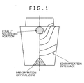
Fig. 1 is a view showing the state of the solidification of a steel ingot produced by an ingot-making method. -
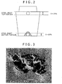
Fig. 2 is a view showing a steel ingot produced by an ingot-making method. -
Fig. 3 is an SEM photograph of a steel cross-section observed at a magnification of 2,000. -
Fig. 4 is an SEM photograph of a steel cross-section observed at a magnification of 200. -
Fig. 5 is an SEM photograph of a steel cross-section observed at a magnification of 200. -
Fig. 6 is a graph showing hydrogen contents at steel ingot upper portions and steel ingot lower portions. -
Fig. 7 is a graph showing the evaluation results on the hydrogen cracking and endurance limit ratios of steel ingots; the ratio of fine inclusions between a steel ingot upper portion and a steel ingot lower portion is shown along the vertical axis, and an S content in steel is shown along the horizontal axis. -
Figs. 8 comprise graphs showing the evaluation of the endurance limit ratios of steel ingots and the occurrence of hydrogen cracking; -
Fig. 8(a) shows the results at steel ingot upper portions andFig. 8(b) shows the results at steel ingot lower portions. - In a steel ingot produced by an ingot-making method, the number density of inclusions increases at a steel ingot lower portion that is a precipitation crystal zone and at a steel ingot upper portion that is a final solidification site as shown in
Fig. 1 . Consequently, the steel ingot lower portion and the steel ingot upper portion: are the portions that markedly affect the hydrogen cracking resistance and fatigue properties of a steel ingot; and are suitable as the portions for specifying the characteristics of the steel ingot. - Here in the present invention, as shown in
Fig. 2 : a steel ingot lower portion is defined as the portion ranging from the bottom end of a steel ingot to thebottom 20% of the total height of the steel ingot in the direction of the gravity (when a precipitation crystal zone appears, inclusions existing at the precipitation crystal zone are also taken into consideration in the above portion); and a steel ingot upper portion is defined as the portion ranging from the top end of the steel ingot to the top 20% of the total height of the steel ingot, respectively. - (Number density of fine inclusions at a steel ingot lower portion (DBOT): 10 to 80 pieces/cm2)
It is possible to improve hydrogen cracking resistance by dispersing fine inclusions in steel as stated above but, in order to exhibit the effect effectively, it is necessary to control the fine inclusions (5 to 10 µm in longest diameter) observed on a steel cross-section at a steel ingot lower portion to not less than 10 pieces/cm2 (preferably not less than 20 pieces/cm2, and yet preferably not less than 30 pieces/cm2) . In contrast, even fine inclusions, if they are contained excessively, as shown in the scanning electron micrographs inFigs. 3 to 5 , inclusion clusters are formed and act as the origins of fatigue fracture in the same way as coarse inclusions. Consequently, it is necessary to control the fine inclusions observed on the steel cross-section to not more than 80 pieces/cm2 (preferably not more than 70 pieces/cm2, and yet preferably not more than 60 pieces/cm2). - In fact, inclusions of less than 5 µm also have hydrogen cracking resistance and hence the inclusions of less than 5 µm may be counted as fine inclusions. Since the inclusions of less than 5 µm have nearly the same distribution characteristic as the inclusions of 5 to 10 µm however, it is enough to count the number of inclusions of 5 to 10 µm in order to evaluate hydrogen cracking resistance. Consequently, the inclusions of less than 5 µm are excluded from an object of the count and thereby the convenience of additional tests is improved.
- At a steel ingot upper portion, it is necessary to control the fine inclusions (5 to 10 µm in longest diameter) observed on a steel cross-section to not less than 20 pieces/cm2 (preferably not less than 30 pieces/cm2, and yet preferably not less than 40 pieces/cm2). In contrast as stated above, even fine inclusions, if they are contained excessively, inclusion clusters are formed and act as the origins of fatigue fracture in the same way as coarse inclusions. Consequently, it is necessary to control the fine inclusions observed on the steel cross-section to not more than 90 pieces/cm2 (preferably not more than 80 pieces/cm2, and yet preferably not more than 70 pieces/cm2).
- Coarse inclusions act as origins of fatigue fracture and hence it is necessary to control the coarse inclusions (not less than 40 µm in longest diameter) observed on a steel cross-section to not more than 5 pieces/cm2 (preferably not more than 4 pieces/cm2, and yet preferably not more than 3 pieces/cm2) at both the steel ingot upper portion and the steel ingot lower portion.
-

The present inventors investigated the hydrogen content in a steel ingot and found that the hydrogen content was higher at the steel ingot upper portion than at the steel ingot lower portion as shown inFig. 6 . Further, the hydrogen cracking resistance and the endurance limit ratio at the steel ingot upper portion were also investigated. The results are shown inFig. 7 . InFig. 7 , (DTOP) / (DBOT) is shown along the vertical axis and [S] is shown along the horizontal axis, and a case where a hydrogen cracking resistance and an endurance limit ratio satisfy certain criteria is rated as the symbol "•" and a case where they do not satisfy the certain criteria is rated as the symbol "×", and the cases are shown in the figure. The criteria for the judgment are the same as the judgment criteria of the "comprehensive evaluation" in Tables 1 to 3 described later. - [S] represents the content (mass ppm) of S in steel. It is understood from
Fig. 7 that, interposing the straight line defined by the expression (DTOP)/(DBOT) = [S]/18 in between, the cases of the symbol "•" appear on the upper side of the straight line and the cases of the symbol "×" appear on the lower side of the straight line, respectively. -
Fig. 7 shows that, in the region where an S content in steel is high, when a value (DTOP) / (DBOT) increases, namely when a fine inclusion content increases at a steel ingot upper portion in comparison with at a steel ingot lower portion, hydrogen cracking occurs at the steel ingot upper portion. It is noteworthy however that, in the region where an S content in steel is low, the hydrogen cracking does not occur even when a value (DTOP)/(DBOT) is not' high. For example, the hydrogen cracking does not occur even when the value (DTOP)/(DBOT) is less than one. - For example, whereas the allowable value of hydrogen in steel is 1.5 ppm in the case where an S content in the steel is 0.003%, the allowable hydrogen value is as very low as 1.0 ppm in the case where an S content is 0.001%. Generally, when one crankshaft is produced from one steel ingot, the range of hydrogen value is roughly from 0.5 to 1.8 ppm.
- As it will be stated later, the present inventors have made it possible to control the hydrogen value to not more than 1.2 ppm and hence it is possible to produce a forging steel ingot without causing hydrogen cracking even when the S content is 0.003% or less. As a result, there arises room for further reducing the S content.
- Generally hydrogen cracking tends to occur when the S content is reduced in order to improve fatigue properties but, from
Fig. 7 , the hydrogen cracking resistance and the fatigue properties can be maintained even when the S content is reduced as long as the condition (DTOP)/(DBOT) ≥ [S]/18 is satisfied. Thereby, it is estimated that the balance between the fatigue properties and the hydrogen cracking resistance in a steel ingot can be improved better than ever. - A forging steel ingot obtained through the above ingot-making process is successively formed into a shape of an intermediate product such as a round bar by hot forging. After the forming, intermediate inspections on compositions, defects, cleanliness, and others are carried out and thereafter, by applying hot forging again, the intermediate product is formed into the shape of a large product such as a solid type crankshaft, a journal, or the like. Successively, after heat treatment is applied in accordance with required product properties, finishing treatment is applied by machining and a final product is produced.
- The following processes are quoted as a concrete procedure for producing a solid type crankshaft from the above forging steel ingot. That is, a completely solidified steel ingot is taken out from a mold and, as preparation for applyinghot forging, heated to preferably 1,150°C or higher, yet preferably 1,180°C or higher, and yet still preferably 1,200°C or higher. Successively, the steel ingot is hot-forged into a round bar or a stepped shape at a forging ratio of 3 or more. On the occasion of the steel ingot forging, the steel ingot may be upset in the direction of the steel ingot height and thereafter subjected to extend forging to a prescribed length in order to compress internal defects. After hot forging, the intermediate product is processed into the shape of a solid type crankshaft. Here, in the event of the forging for forming of the solid type crankshaft, either throws may be formed one by one or a plurality of throws may be formed simultaneously by blocking the whole body. After the forging forming, a solid type crankshaft of a prescribed size is produced by machining for finishing. Otherwise a solid type crankshaft may be produced by forming into a stepped shape through hot forging and thereafter applying machining. Still otherwise the solid type crankshaft maybe structured so as to have a flange on one end of the crankshaft or flanges on both the ends thereof. The number of throws is 3 to 12 for example.
- Although the present invention is characterized by controlling the size and number density of inclusions existing in a steel as explained above and the basic composition of the steel is not particularly limited, in order to satisfy strength, toughness, and moreover fatigue properties required of a crankshaft for example, it is desirable to satisfy the following basic composition in consideration of the general technological level on steel.
- C is an element contributing to the improvement of strength and, in order to give sufficient strength to a crankshaft, C may be contained, for example, by: 0.2% or more; preferably 0.25% or more; and yet preferably 0.3% or more. If the C content is excessive however, the toughness of the crankshaft deteriorates, and hence C is controlled, for example, to: 0.6% or less; preferably 0.55% or less; and yet preferably 0.5% or less.
- Si functions as a strength improving element and, in order to give sufficient strength to a crankshaft, Si may be contained, for example, by: 0.05% or more; preferably 0.1% or more; and yet preferably 0.15% or more. If Si is excessive however, inverted-V-shaped segregation becomes marked and a clean steel ingot is hardly obtained, and hence Si is controlled, for example, to: 0.5% or less; preferably 0.45% or less; and yet preferably 0.4% or less.
- Mn is an element enhancing hardenability and also contributing to the improvement of strength and, in order to secure both sufficient strength and hardenability, Mn is desirably contained, for example, by: 0.2% or more; preferably 0.5% or more; and yet preferably 0.8% or more. If Mn is excessive however, inverted-V-shaped segregation may be furthered in some cases, and hence Mn is controlled, for example, to: 1.2% or less; preferably 1.1% or less; and yet preferably 1% or less.
- Ni is useful as a toughness improving element and it is recommended to contain Ni, for example, by: 0.1% or more; and preferably 0.2% or more. If the Ni amount is excessive however, the cost increases, and hence Ni is controlled to: 3.5% or less; and preferably 3% or less.
- Cr is an element effective in enhancing hardenability and improving toughness and, in order to exhibit such functions, Cr is contained, for example, by: 0.9% or more; preferably 1.1% or more; and yet preferably 1.3% or more. If Cr is excessive however, inverted-V-shaped segregation may be furthered and a high cleanliness steel is hardly produced in some cases, and hence Cr is controlled, for example, to: 2.5% or less; preferably 2.3% or less; andyetpreferably 2.1% or less.
- Mo is an element effectively functioning for the improvement of hardenability, strength, and toughness and, in order to exhibit such functions effectively, Mo is contained, for example, by: 0.1% or more; preferably 0.2% or more; and yet preferably 0.25% or more. Mo has a small equilibrium distribution coefficient and is likely to form microsegregation (normal segregation) however, and hence Mo is controlled, for example, to: 0.7% or less; preferably 0.6% or less; and yet preferably 0.5% or less.
- V has the effects of precipitation hardening and structure fractionation and is an element useful for enhancing the strength of steel. In order to exhibit such functions effectively, it is recommendedto containV, for example, by: 0.005% or more; and preferably 0.01% or more. When V is contained excessively however, the above effects are saturated and that is inefficient economically, and hence V is controlled to: 0.2% or less; and preferably 0.15% or less.
- Al is effective as a deoxidizing element in a steel making process and also effective for the cracking resistance of steel. Consequently, it is recommended to contain Al, for example, by: 0.01% or more; and preferably 0.015% or more. In contrast, Al fixes N in the form of AlN or the like, hinders the strengthening function of steel by the blend of N, V, and others, combines with various other elements, yields nonmetallic inclusions and intermetallic compounds, and deteriorates the toughness of steel in some cases, and hence Al is controlled, for example, to: 0.1% or less; and preferably 0.08% or less.
- S is likely to form coarse inclusions in a forging steel and hence may deteriorate the fatigue strength of a forging steel ingot or a crankshaft in some cases. Consequently, the S content in steel is controlled, for example, to: 0.005% or less; preferably 0.0045% or less; yet preferably 0.004% or less; and yet still preferably 0.0035% or less.
- Meanwhile, when fine S-type inclusions are contained by a certain number density or more in a forging steel, many stress fields are formed in the steel, and thus the fine S-type inclusions are likely to trap excessive hydrogen exceeding a solid solubility limit in the steel and have the effect of improving the hydrogen cracking resistance of the steel.
- In order to secure such S-type inclusions, the S content in steel is controlled to: 0.0002% or more; preferably 0.0004% or more; yet preferably 0.0006% or more; and yet still preferably 0.0008% or more.
- An S content can be adjusted by controlling the composition of slag during melt refining. More specifically, the S content in steel can be reduced by raising the ratio of a CaO content to an SiO2 content (CaO/SiO2, hereunder referred to as "C/S" occasionally) in slag. Further, as a complimentary means, the S content in steel can be reduced by raising the ratio of a CaO content to an Al2O3 content (CaO/Al2O3, hereunder referred to as "C/A" occasionally). Inversely, when the S content is wanted to be increased, the slag composition is adjusted so that C/S and/or C/A may be reduced.
- Ti forms coarse nitrides in steel and deteriorates the fatigue strength of a forging steel ingot or a crankshaft in some cases. Consequently, the Ti content in steel is controlled, for example: to 0.005% or less; preferably 0.004% or less; and yet preferably 0.003% or less. Here, Ti makes fine inclusions such as TiN, TiC, and Ti4C2S2, disperses in steel, occludes and traps excessive hydrogen exceeding a solid solubility limit in the steel, and has the effect of improving the hydrogen cracking resistance of the steel. When such Ti-type inclusions are secured, the Ti content in steel is controlled, for example, to: 0.0002% or more; preferably 0.0004% or more; and yet preferably 0.0006% or more.
- A Ti content can be adjusted by regulating the ratio between a used amount of an alloy having a high impurity Ti content (a low grade alloy) and a used amount of an alloy having a low impurity Ti content (a high grade alloy) in auxiliary materials.
- O (oxygen) is an element that forms oxides such as SiO2, Al2O3, MgO, CaO, and others, turns into inclusions, and deteriorates the fatigue strength of a steel ingot. Consequently, it is desirable to reduce O to the utmost and the total oxygen amount is controlled to: 0.0015% or less; and preferably 0.001% or less.
- The basic compositions of a forging steel used in the present invention are preferably as stated above and the remainder comprises Fe substantially but unavoidable impurities may be contained in the steel. As the unavoidable impurities, for example P and N are quoted and for example the content of P is: preferably 0.03% or less; and yet preferably 0.02% or less. Further, it is also possible to use a forging steel further containing another element intentionally within the range not adversely affecting the aforementioned functions of the present invention.
- The examples of another element that can be added intentionally are B having a hardenability improving effect, and W, Nb, Ta, Cu, Ce, Zr, Te, and others that are solid solution strengthening elements or precipitation strengthening elements. The elements can be added independently or in combination of two or more kinds. A desirable addition amount of the elements is, for example, about 0.1% or less in total.
- The present invention is hereunder explained more concretely with examples. However, the present invention is substantially not limited to the examples and may be modified appropriately within the range conforming to the aforementioned and after-mentioned gists, and all of those modifications are included in the technological scope of the present invention.
- It is recommended to refine steel by the method explained below in order to: increase the cleanliness of molten steel poured into a mold; thereby control the number density (DBOT) of
inclusions 5 to 10 µm in longest diameter observed on a steel cross-section to about 10 to 80 pieces/cm2 at a steel ingot lower portion, the number density (DTOP) ofinclusions 5 to 10 µm in longest diameter observed on a steel cross-section to about 20 to 90 pieces/cm2 at a steel ingot upper portion, and the number density ofinclusions 40 µm or more in longest diameter to about 5 pieces/cm2 or less; and satisfy the expression (1). - The refining method is a method for producing high cleanliness steel by:applying first secondary-refining to molten steel tapped from a converter or an electric furnace; applying degassing treatment to the molten steel after subjected to the first secondary-refining; and applying second secondary-refining to the molten steel after subjected to the degassing treatment.
- That is, in order to produce high cleanliness steel having a small amount of inclusions caused by slag inclusion and a high cleanliness, it is effective to apply secondary-refining twice in the order of secondary-refining treatment, degassing treatment, and then secondary-refining treatment again to molten steel produced with a converter.
- The first secondary-refining treatment is a treatment to adjust molten steel compositions to prescribed values and the degassing treatment is a treatment to remove gas components such as hydrogen existing in the molten steel. Hence it is necessary to increase an agitation power density at both the treatments while suppressing the inclusion of slag floating on the surface of the molten steel to the minimum.
- Meanwhile, the function of surfacing and separating the slag once included in the molten steel during the degassing treatment is given to the second secondary-refining treatment and it is necessary to agitate the molten steel at a low agitation power density so as not to cause additional slag inclusion while the molten steel is heated and retained.
- More specifically, at the first secondary treatment, the flow rate of injected gas is adjusted so that the agitation power density may be 5 W'/ton or more (preferably 10 W/ton or more) and 60 W/ton or less (preferably 50 W/ton or less) and slag conditioning is carried out so that the slag composition after the degassing treatment may satisfy the expressions CaO/SiO2 ≥ 3.5, CaO/Al2O3 = 1.5 - 3.5, and T. Fe + MnO ≤ 1.0, in terms of mass%. Here, T.Fe means the total amount of iron atoms.
- At the degassing treatment, the flow rate of injected gas is adjusted so that the agitation power density may be 50 W/ton or more and preferably 60 W/ton or more and 200 W/ton or less and preferably 180 W/ton or less up to the midterm (the halfway) of the degassing treatment and the flow rate of injected gas is adjusted so that the agitation power density may be 140 W/ton or less and preferably 120 W/ton or less (excluding 0 W/ton) at the succeeding degassing treatment (after the midterm).
- At the second secondary treatment, the flow rate of injected gas is adjusted so that the agitation power density may be 25 W/ton or less and preferably 20 W/ton or less (excluding 0 W/ton).
- More specifically, the following procedures are taken.
- Firstly, molten steel tapped from a converter or an electric furnace to a ladle is conveyed to a secondary-refining apparatus and first secondary-refining treatment (hereunder referred to as LF-I occasionally) is applied. Stillmore specifically, whilemolten steel is heated to TL = about 1,600°C by generating arc discharge, flux is added by a flux supply means and further the molten steel is agitated by injecting Ar gas by a gas injection means. With regard to strength for agitating the molten steel, the flow rate of Ar gas is adjusted so that the agitation power density ε computed with the expression (2) below may be 5 to 60 W/ton.
- Here, in the computation of the agitation power density ε, the temperature of bottom blow gas before injection To (the temperature of Ar gas before injected) is set at room temperature (298K) and the temperature of bottom blow gas after injection Tg (the temperature of Ar gas after injected) is set at the molten steel temperature TL.
- The main purposes of LF-I where molten steel tapped from a converter or an electric furnace to a ladle is primarily refined are to heat the molten steel and to adjust the compositions of the molten steel. The molten steel compositions and the molten steel temperature cannot be homogenized unless appropriate agitation is applied on this occasion. Excessive agitation of the molten steel however tends to entangle slag even when the compositions and the temperature are homogeneous and the slag inclusionmay act as the origins of defects afterward. Consequently, the agitation power density ε is set at 5 to 60 W/ton. By so doing, it is possible to homogenize the compositions and temperature of the molten steel while slag inclusion is prevented.
-

- ε: Agitation power density (W/ton)
T0: Temperature of bottom blow gas before injection (room temperature (298K))
TL: Molten steel temperature (K)
ML: Molten steel quantity (ton)
ρL: Molten steel density (kg/m3)
Qg: Flow rate of bottom blow gas (Nl/min)
Tg: Temperature of bottom blow gas after injection (K)
P: Atmospheric pressure (torr)
H0: Molten steel depth (m) - For example, in the first secondary-refining treatment (LF-I), even though some conditions such as the size of the ladle and the actually charged molten steel quantity ML are different, the agitation power density ε takes a value of 4.7 to 67.2 W/ton by adjusting Qg/ ML to 0.30 to 3.75 Nl/min·ton.
- Here, in LF-I, with regard to the type and the quantity of flux, the heating temperature is controlled and the charging amount of an auxiliary material (flux) is adjusted so that the slag composition may simultaneously satisfy the following three conditions after the finish of vacuum degassing treatment that will be stated later (in other words, at the start of the second secondary-refining treatment) ;
- (1) the mass of CaO is 3.5 times or more the mass of SiO2,
- (2) the mass of CaO is 1.5 to 3.5 times the mass of Al2O3, and
- (3) the summation of the mass of T. Fe and the mass of MnO in the slag composition is 1.0% or less of the total slag mass.
- After finishing the first secondary-refining treatment, the molten steel is conveyed together with the ladle to a vacuumdegassing apparatus and vacuum degassing treatment (hereunder referred to as VD occasionally) is applied to the molten steel. More specifically, the atmospheric pressure P in the ladle is reduced close to a vacuum of about 0.5 Torr by activating an exhaust system and thereby evacuating the gas existing above the molten steel in the ladle through an exhaust pipe. In addition, the molten steel is agitated by injecting Ar gas through a gas injecting means. By the above method, the gas component such as hydrogen existing in the molten steel is removed.
- The time for VD is about 20 minutes in total and, during the former half time (before the midterm in the treatment time, the
former half 10 minutes), the bottom blow gas flow rate Qg is adjusted so that the agitation power density ε may be 50 to 200 W/ton and, during the latter half time (after the midterm in the treatment time, thelatter half 10 minutes), the bottom blow gas flow rate Qg is adjusted so that the agitation power density ε may be 140 W/ton or less (excluding 0 W/ton). - In VD, hydrogen is removed from the molten steel the composition adjustment of which is almost finished and, on this occasion too, it is desirable to adopt an agitation power density ε that can prevent slag from being included in the molten steel and can attain dehydrogenation at the same time. To that end, by controlling the agitation power density ε to 50 to 200 W/ton during the former half of the VD treatment time, dehydrogenation can be attained efficiently while suppressing slag inclusion to the minimum. In addition, by controlling the agitation power density ε to 140 W/ton or less during the latter half time of VD, the surfacing and separation of the entangled slag can be accelerated.
- Further, in the case of the present embodiment, a high cleanliness steel can be produced by applying the second secondary-refining (hereunder referred to as LF-II occasionally) to the molten steel after subjected to VD. That is, after the vacuum degassing treatment is finished, the molten steel is conveyed to the secondary-refining treatment apparatus together with the ladle and the second secondary-refining treatment is applied to the molten steel. More specifically, while the molten steel is heated to TL = about 1, 600°C by generating arc discharge, the molten steel is agitated by injecting Ar gas by a gas injection means. With regard to the strength for agitating the molten steel, the Ar gas flow rate Qg is adjusted so that the agitation power density ε computed with the expression (2) may be 25 W/ton or less (excluding 0 W/ton).
- By applying the LF treatment (LF-II) again in this way, it is possible to further promote "the surfacing and separation of entangled slag and deoxidation products" occurring from the midterm of VD. On this occasion, the agitation power density ε in LF-II must be 25 W/ton or less in order to prevent additional slag inclusion. By heating and retaining the molten steel at the agitation power density ε, the surfacing and separation of the slag and the deoxidation products can be attained without fail.
- Here as stated above, the slag composition in LF-II satisfies the following conditions;
- (1) basicity, namely CaO/SiO2 ≥ 3.5,
- (2) CaO/ Al2O3 = 1.5 - 3.5, and
- (3) T.Fe + MnO ≤ 1.0 mass %,
- By adopting the production method of a high cleanliness steel as stated above, it is possible to produce a high cleanliness steel having a small amount of inclusions caused by slag inclusion.
- A steel ingot is produced by pouring the obtained high cleanliness molten steel into a mold of 10 to 90 tons class (2 to 4 m in total height) through a bottom pouring ingot-making method. The solidified steel ingot is demolded, thereafter heated to about 1, 300°C, hot-forged, and produced into a forged material with 150 to 700 mm in cross-sectional diameter. The hot forging is applied by elongating the steel ingot with a pressing machine and thereafter forming into a round cross-section with a special purpose tool.
- In Tables 1 to 3, shown are: the conditions (Conditions 1 to 20) that the agitation power density ε in LF-I, the agitation power density ε during the former half time of VD, the agitation power density ε during the latter half time of VD, and the agitation power density ε in LF-II are variously changed; moreover various conditions of the tests (Test numbers 1 to 59) carried out by changing the basicity (CaO/SiO2) and the values of CaO/ Al2O3 and T.Fe + MnO (mass %); and the data of the physical properties of the test pieces cut out from the upper portions and the lower portions of the obtained steel ingots.
- Here, in Tables 1 to 3, in the row "Composition and temperature homogenization", when the variation of the C content is defined as ΔC and the variation of temperature is defined as ΔT from the beginning to the end of the casting of the steel ingot, a case satisfying the expressions ΔC ≤ 0.01% and ΔT ≤ 20°C is rated as the symbol ○ and the other cases are rated as the symbol ×.
In the row "Hydrogen removal", the hydrogen content [H] is measured immediately before the end of refining, and a case satisfying the expression [H] ≤ 1.2 ppm is rated as the symbol ○ and a case satisfying the expression [H] > 1.2 ppm is rated as the symbol ×.
In the row "Slag inclusion", a case where the number ofinclusions 5 µm or more in longest diameter in the microscopic surface observation of a molten steel sample having a Ca content of 5% or more is 30 pieces/cm2 or less is rated as the symbol ○ and a case where the number exceeds 30 pieces/cm2 is rated as the symbol ×. - In Tables 1 to 3, the S content (mass ppm) in steel, the number density of fine inclusions (5 to 10 µm in longest diameter) at a portion corresponding to the upper portion of a steel ingot (DTOP), the number density of fine inclusions (5 to 10 µm in longest diameter) at a portion corresponding to the lower portion of a steel ingot (DBOT). the number density of coarse inclusions (40 µm or more in longest diameter) at a portion corresponding to the upper portion of a steel ingot, and the number density of coarse inclusions (40 µm or more in longest diameter) at a portion corresponding to the lower portion of a steel ingot are shown for each of the test pieces. The number of inclusions is obtained by examining the number of inclusions per 1 cm2 on a microscopic surface of a test piece with an EPMA (JXA-8900L made by JEOL Ltd.).
- Here, the chemical compositions in steel of the test pieces are C: 0.3%, Si: 0.25%, Mn: 0.55%, Ni: 1.6%, Cr: 1.6%, Mo: 0.25%, V: 0.01%, Al: 0.03%, S: 0.002%, Ti: 0.003%, O: 0.0013%, and P: 0.01%.
- Further, the value of (DBOT)/(DTOP) × S content in steel (mass ppm) (the expression (1) is satisfied when the value is 18 or less), the size of the largest inclusion (the symbol ○ represents the case of the largest size (φ: sphere diameter conversion) < 0.5 mm, the symbol △ represents the case of 0.5 mm < the largest size ≤ 1.0 mm, and the symbol × represents the case of the largest size > 1.0 mm), and cleanliness are measured and the obtained results are also shown in Tables 1 to 3. Here, the results in a case where the upper portion (T) or the lower portion (B) of a steel ingot is not distinctively identified mean the test results of the upper portion of a steel ingot.
- Note that, in the row "Cleanliness", a case of DIN K(3) ≤ 15 is rated as the symbol ○ and a case of DIN K(3) > 15 is rated as the symbol × as the DIN K3 standards, and the cleanliness is rated as the symbol ○ in a case where a steel ingot upper portion is rated as the symbol ○ and also a steel ingot lower portion is rated as the symbol ○, the cleanliness is rated as the symbol Δ in a case where either of a steel ingot upper portion or a steel ingot lower portion is rated as the symbol ○ and the other thereof is rated as the symbol ×, and the cleanliness is rated as the symbol × in a case where both of a steel ingot upper portion and a steel ingot lower portion are rated as the symbol ×.
- Further, in Tables 1 to 3, the endurance limit ratios at the upper portion and the lower portion of a steel ingot and the test results of hydrogen cracking at the upper portion and the lower portion of a steel ingot are described.
- An endurance limit ratio = fatigue strength/tensile strength is obtained from the results of a tensile strength test and a fatigue strength test that are described later. The endurance limit ratios of a steel ingot upper portion (T) and a steel ingot lower portion (B) are separately shown in Tables 1 to 3.
- Then, the results of judging the endurance limit ratio are also shown in Tables 1 to 3 showing with the symbol ○ in a case of Endurance limit ratio ≥ 0.45, the symbol Δ in a case of 0.40 ≤ Endurance limit ratio < 0.45, and the symbol × in a case of Endurance limit ratio < 0.40.
- Tensile test pieces 6 mm in diameter and 30 mm in gauge length (two test pieces for each) are: sampled from the vicinity of the center of a round bar steel after forging; and subjected to tensile tests (JIS Z 2204 and 2241) at room temperature. The test results of a steel ingotupperportion (T) anda steel ingot lowerportion (B) are separately shown with the unit of MPa in Tables 1 to 3.
- Rotating bending fatigue tests are carried out with the test pieces shown below. The test results of a steel ingot upper portion (T) and a steel ingot lower portion (B) are separately shown with the unit of MPa in Tables 1 to 3.
Test piece:smooth test piece 10 mm in diameter,
Test method: rotating bending fatigue test (stress ratio = -1, revolutions: 3,600 rpm),
Fatigue strength evaluation method: step method,
Step stress: 20 MPa,
Number of test pieces: five pieces each, and
- Ultrasonic detection test (UT) is carried out at a frequency of 4 MHz (more specifically, "Defects of Forged Steel Products", edited by Forged Steel Study Section, Japan Steel Castings and Forgings Association, P32-33). A case where a defect echo showing hydrogen cracking is detected at the intermediate portion (1/3 to 1/5R) of a steel ingot is represented with the symbol × regarding the steel ingot as being inferior in hydrogen cracking resistance and a case where a defect echo is not detected is represented with the symbol ○ regarding the steel ingot as being superior in hydrogen cracking resistance. Here, when the side face (surface layer) in the steel ingot width direction is represented by 0R and the center is represented by 1/2R, the center portion is defined as a portion located in the range of 1/2 to 1/3R, the intermediate portion is defined as a portion located in the range of 1/3 to 1/5R, and the surface layer portion is defined as a portion located in the range of 0R to 1/5R.
- In the row "Comprehensive evaluation", a case where all of the endurance limit ratios at a steel ingot upper portion and a steel ingot lower portion and the test results of hydrogen cracking at a steel ingot upper portion and a steel ingot lower portion are rated as the symbol ○ is rated as the symbol •, and the other cases are rated as the symbol ×.
-


- Here, in Test numbers 41, 49, and 55 in Table 3, the reason why the endurance limit ratios (B) are rated as the symbol × even though the numbers of coarse inclusions at the steel ingot lower portions are smaller than the standard value is that the hydrogen cracking occurs in the test pieces and the fatigue strength deteriorates due to the cracking.
- Further, in
Fig. 8(a) , the number density (DTOP) of fine inclusions (5 to 10 µm in longest diameter) at the portion corresponding to a steel ingot upper portion is shown along the vertical axis, and the number density of coarse inclusions (40 µm or more in longest diameter) at the portion corresponding to a steel ingot upper portion is shown along the horizontal axis. Then a case where the comprehensive evaluation is rated as the symbol • is shown with the symbol •, and a case where either of the endurance limit ratio or the test result of hydrogen cracking is rated as the symbol × is shown with the symbol ×. In a case where the value (DTOP) is lower than 20 pieces/cm2, hydrogen cracking occurs and the case is rated as the symbol ×. - Yet further, in a case where the value (DTOP) exceeds 90 pieces/cm2 and a case where the number density of
inclusions 40 µm or more in longest diameter exceeds 5 pieces/cm2, a prescribed endurance limit ratio is not obtained and the cases are rated as the symbol ×. - Furthermore, in
Fig. 8(b) , the number density (DBOT) of fine inclusions (5 to 10 µm in longest diameter) at the portion corresponding to a steel ingot lower portion is shown along the vertical axis, and the number density of coarse inclusions (40 µm or more in longest diameter) at the portion corresponding to a steel ingot lower portion is shown along the horizontal axis. Then a case where the comprehensive evaluation is rated as the symbol ● is shown with the symbol ●, and a case where either of the endurance limit ratio or the test result of hydrogen cracking is rated as the symbol × is shown with the symbol ×. In a case where the value (DBOT) is lower than 10 pieces/cm2, hydrogen cracking occurs and the case is rated as the symbol ×. - In addition, in a case where the value (DBOT) exceeds 80 pieces/cm2 and a case where the number density of
inclusions 40 µm or more in longest diameter exceeds 5 pieces/cm2, a prescribed endurance limit ratio is not obtained and the cases are rated as the symbol ×.
Claims (3)
- A forging steel ingot cast with a mold wherein:the number density DBOT of inclusions 5 to 10 µm in longest diameter observed on a steel cross-section is 10 to 80 pieces/cm2 at the steel ingot lower portion ranging from the bottom end of the steel ingot to the bottom 20% of the total height of the steel ingot in the direction of the gravity;the number density DTOP of inclusions 5 to 10 µm in longest diameter observed on a steel cross-section is 20 to 90 pieces/cm2 at the steel ingot upper portion ranging from the top end of the steel ingot to the top 20% of the total height of the steel ingot;the number density of inclusions 40 µm or more in longest diameter observed on a steel cross-section is 5 pieces/cm2 or less at both of the steel ingot lower portion and said steel ingot upper portion; andthe following expression (1) is satisfied,

here, [S] represents the content (in mass ppm) of S in steel. - A forging steel ingot according to Claim 1, comprising
C: 0.2 to 0.6% (in mass %, the same is applied hereunder),
Si: 0.05 to 0.5%,
Mn: 0.2 to 1.2%,
Ni: 0.1 to 3.5%,
Cr: 0.9 to 2.5%,
Mo: 0.1 to 0.7%,
V: 0.005 to 0.2%,
Al: 0.01 to 0.1%,
S: 0.005% or less,
Ti: 0.005% or less, and
O: 0.0015% or less,
with the remainder composed of iron and unavoidable impurities. - A solid type crankshaft produced by hot-forging a forging steel ingot according to Claim 1 or 2.
Applications Claiming Priority (4)
| Application Number | Priority Date | Filing Date | Title |
|---|---|---|---|
| JP2007089336 | 2007-03-29 | ||
| JP2007167849A JP5089267B2 (en) | 2007-06-26 | 2007-06-26 | Integrated crankshaft |
| JP2007207100A JP4160103B1 (en) | 2007-03-29 | 2007-08-08 | Steel ingot for forging |
| PCT/JP2008/054966 WO2008120574A1 (en) | 2007-03-29 | 2008-03-18 | Steel ingot for forging and integral crankshaft |
Publications (3)
| Publication Number | Publication Date |
|---|---|
| EP2141254A1 true EP2141254A1 (en) | 2010-01-06 |
| EP2141254A4 EP2141254A4 (en) | 2011-09-14 |
| EP2141254B1 EP2141254B1 (en) | 2016-05-04 |
Family
ID=39808156
Family Applications (1)
| Application Number | Title | Priority Date | Filing Date |
|---|---|---|---|
| EP08722360.8A Not-in-force EP2141254B1 (en) | 2007-03-29 | 2008-03-18 | Steel ingot for forging and integral crankshaft |
Country Status (6)
| Country | Link |
|---|---|
| EP (1) | EP2141254B1 (en) |
| KR (1) | KR101121313B1 (en) |
| CN (1) | CN101631886B (en) |
| ES (1) | ES2572612T3 (en) |
| PL (1) | PL2141254T3 (en) |
| WO (1) | WO2008120574A1 (en) |
Cited By (5)
| Publication number | Priority date | Publication date | Assignee | Title |
|---|---|---|---|---|
| EP2527476A1 (en) * | 2011-05-27 | 2012-11-28 | A. Finkl & Sons Co. | Flexible minimum energy utlilisation electric arc furnace system and processes for making steel products. |
| US8511903B2 (en) | 2009-02-17 | 2013-08-20 | Jtekt Corporation | Wheel bearing device and manufacturing method therefor |
| EP2671963A1 (en) * | 2012-06-06 | 2013-12-11 | Kabushiki Kaisha Kobe Seiko Sho (Kobe Steel, Ltd.) | High strength large steel forging |
| EP2169082B1 (en) * | 2008-09-30 | 2015-07-08 | Kabushiki Kaisha Kobe Seiko Sho | Forged product with a steel composition containing 0.15-0.75%C, Si, Mn, Ni, Cr, Mo, V and Al and crankshaft manufactured from it |
| EP3511434A4 (en) * | 2016-11-09 | 2020-03-18 | Jiang Yin Xing Cheng Special Steel Works Co., Ltd | METHOD FOR PRODUCING LS-CRNIMO30C STEEL FORGE FROM A CONTINUOUS CASTING TICKET FOR A SUBSEA OIL PRODUCTION WELL HEAD DEVICE |
Families Citing this family (7)
| Publication number | Priority date | Publication date | Assignee | Title |
|---|---|---|---|---|
| CN101886227A (en) * | 2010-06-23 | 2010-11-17 | 抚顺泰平铸造有限公司 | ZG28Cr3Ni3Mo steel grade |
| CN104328327A (en) * | 2014-11-17 | 2015-02-04 | 柳州市二和汽车零部件有限公司 | Crankshaft gear for automobile |
| CN104533958A (en) * | 2014-11-17 | 2015-04-22 | 柳州市二和汽车零部件有限公司 | Automobile bearing shell |
| CN104358855A (en) * | 2014-11-17 | 2015-02-18 | 柳州市二和汽车零部件有限公司 | Oil pump driving gear for automobile |
| CN104455051A (en) * | 2014-11-17 | 2015-03-25 | 柳州市二和汽车零部件有限公司 | Universal joint pin for automobile |
| CN106987779B (en) * | 2017-05-11 | 2018-08-03 | 北京科技大学 | A kind of metallurgical method of high-strength tenacity crankshaft steel Intragranular Acicular Ferrite |
| US11890668B2 (en) * | 2022-06-14 | 2024-02-06 | GM Global Technology Operations LLC | System and method of making a cast steel alloy crankshaft having low porosity |
Family Cites Families (6)
| Publication number | Priority date | Publication date | Assignee | Title |
|---|---|---|---|---|
| JPH09329147A (en) * | 1996-04-10 | 1997-12-22 | Nippon Seiko Kk | Water resistant long life rolling bearing |
| JPH108132A (en) | 1996-06-14 | 1998-01-13 | Sumitomo Metal Ind Ltd | Manufacturing method of thick steel plate with excellent toughness |
| JPH1025536A (en) | 1996-07-11 | 1998-01-27 | Sumitomo Metal Ind Ltd | Steel material excellent in toughness of welded heat-affected zone and method for producing the same |
| JP3491612B2 (en) | 2000-12-28 | 2004-01-26 | 愛知製鋼株式会社 | Crankshaft steel with excellent machinability and wear resistance |
| JP4658695B2 (en) | 2005-06-03 | 2011-03-23 | 株式会社神戸製鋼所 | Forging steel and crankshaft with excellent hydrogen cracking resistance |
| JP4502929B2 (en) * | 2005-10-20 | 2010-07-14 | 株式会社神戸製鋼所 | Case hardening steel with excellent rolling fatigue characteristics and grain coarsening prevention characteristics |
-
2008
- 2008-03-18 CN CN2008800056584A patent/CN101631886B/en not_active Expired - Fee Related
- 2008-03-18 ES ES08722360.8T patent/ES2572612T3/en active Active
- 2008-03-18 PL PL08722360.8T patent/PL2141254T3/en unknown
- 2008-03-18 KR KR1020097020253A patent/KR101121313B1/en not_active Expired - Fee Related
- 2008-03-18 WO PCT/JP2008/054966 patent/WO2008120574A1/en not_active Ceased
- 2008-03-18 EP EP08722360.8A patent/EP2141254B1/en not_active Not-in-force
Cited By (7)
| Publication number | Priority date | Publication date | Assignee | Title |
|---|---|---|---|---|
| EP2169082B1 (en) * | 2008-09-30 | 2015-07-08 | Kabushiki Kaisha Kobe Seiko Sho | Forged product with a steel composition containing 0.15-0.75%C, Si, Mn, Ni, Cr, Mo, V and Al and crankshaft manufactured from it |
| US8511903B2 (en) | 2009-02-17 | 2013-08-20 | Jtekt Corporation | Wheel bearing device and manufacturing method therefor |
| EP2527476A1 (en) * | 2011-05-27 | 2012-11-28 | A. Finkl & Sons Co. | Flexible minimum energy utlilisation electric arc furnace system and processes for making steel products. |
| AU2012202044B2 (en) * | 2011-05-27 | 2014-04-10 | A. Finkl & Sons Co. | Flexible minimum energy utilization electric arc furnace system and processes for making steel products |
| RU2530578C2 (en) * | 2011-05-27 | 2014-10-10 | А. Финкл энд Санс Ко. | Flexible electric arc furnace with minimum electric power consumption and method of steel products fabrication |
| EP2671963A1 (en) * | 2012-06-06 | 2013-12-11 | Kabushiki Kaisha Kobe Seiko Sho (Kobe Steel, Ltd.) | High strength large steel forging |
| EP3511434A4 (en) * | 2016-11-09 | 2020-03-18 | Jiang Yin Xing Cheng Special Steel Works Co., Ltd | METHOD FOR PRODUCING LS-CRNIMO30C STEEL FORGE FROM A CONTINUOUS CASTING TICKET FOR A SUBSEA OIL PRODUCTION WELL HEAD DEVICE |
Also Published As
| Publication number | Publication date |
|---|---|
| CN101631886A (en) | 2010-01-20 |
| WO2008120574A1 (en) | 2008-10-09 |
| KR101121313B1 (en) | 2012-03-22 |
| KR20090115886A (en) | 2009-11-09 |
| ES2572612T3 (en) | 2016-06-01 |
| PL2141254T3 (en) | 2016-10-31 |
| EP2141254A4 (en) | 2011-09-14 |
| EP2141254B1 (en) | 2016-05-04 |
| CN101631886B (en) | 2011-05-11 |
Similar Documents
| Publication | Publication Date | Title |
|---|---|---|
| EP2141254B1 (en) | Steel ingot for forging and integral crankshaft | |
| JP5093422B2 (en) | High strength steel plate and manufacturing method thereof | |
| EP2110454B1 (en) | Forging steel, and forged products obtainable therefrom | |
| KR101492782B1 (en) | Steel sheet | |
| EP2050832A1 (en) | Two-phase stainless steel | |
| EP1444373A1 (en) | STEEL PLATE HAVING SUPERIOR TOUGHNESS IN WELD HEAT&minus;AFFECTED ZONE AND METHOD FOR MANUFACTURING THE SAME&comma; WELDING FABRIC USING THE SAME | |
| JP5158272B2 (en) | High-strength steel sheet with excellent stretch flangeability and bending workability and method for producing the molten steel | |
| WO2002048417A1 (en) | STEEL PLATE TO BE PRECIPITATING TiN + ZrN FOR WELDED STRUCTURES, METHOD FOR MANUFACTURING THE SAME AND WELDING FABRIC USING THE SAME | |
| WO2002044436A1 (en) | Steel plate to be precipitating tin+mns for welded structures, method for manufacturing the same and welding fabric using the same | |
| CN105143490B (en) | Steel plate | |
| CN115488298B (en) | A continuous casting billet for high carbon steel wire and a preparation method thereof | |
| CN113913676B (en) | Metallurgy method for improving morphology of as-cast sulfide of medium-carbon high-sulfur free-cutting steel | |
| CN102015156B (en) | Method for manufacturing low carbon steel sheet | |
| JP5089267B2 (en) | Integrated crankshaft | |
| CN112962016B (en) | Grain size refining method for alloy structural steel | |
| JP4160103B1 (en) | Steel ingot for forging | |
| EP3831978A1 (en) | Ti- and nb-added ferritic stainless steel excellent in low-temperature toughness of welds | |
| JP3870614B2 (en) | Cold-rolled steel sheet having excellent surface properties and internal quality and method for producing the same | |
| JP7743935B2 (en) | Continuously cast slab and its manufacturing method | |
| JP7063401B2 (en) | Manufacturing method of high manganese steel slab and manufacturing method of high manganese steel slab or steel plate | |
| JP4299757B2 (en) | Thin steel plate and slab excellent in surface properties and internal quality, and method for producing the same | |
| JP4516923B2 (en) | Continuously cast slab of aluminum killed steel and method for producing the same | |
| CN117385277B (en) | Prestressed concrete sleeper reinforcement raw material hot-rolled wire rod and preparation method thereof | |
| CN117344229B (en) | A high-wear-resistant high-carbon high-manganese steel and its production method | |
| JPH0790504A (en) | Secondary cooling method for low-temperature Ni-containing steel and continuous cast slab thereof |
Legal Events
| Date | Code | Title | Description |
|---|---|---|---|
| PUAI | Public reference made under article 153(3) epc to a published international application that has entered the european phase |
Free format text: ORIGINAL CODE: 0009012 |
|
| 17P | Request for examination filed |
Effective date: 20091022 |
|
| AK | Designated contracting states |
Kind code of ref document: A1 Designated state(s): AT BE BG CH CY CZ DE DK EE ES FI FR GB GR HR HU IE IS IT LI LT LU LV MC MT NL NO PL PT RO SE SI SK TR |
|
| DAX | Request for extension of the european patent (deleted) | ||
| A4 | Supplementary search report drawn up and despatched |
Effective date: 20110811 |
|
| RIC1 | Information provided on ipc code assigned before grant |
Ipc: C21C 7/10 20060101ALI20110805BHEP Ipc: C21C 7/00 20060101ALI20110805BHEP Ipc: B22D 7/00 20060101ALI20110805BHEP Ipc: C22C 38/50 20060101ALI20110805BHEP Ipc: C21C 7/072 20060101ALI20110805BHEP Ipc: C22C 38/00 20060101AFI20110805BHEP Ipc: C22C 38/60 20060101ALI20110805BHEP |
|
| REG | Reference to a national code |
Ref country code: DE Ref legal event code: R079 Ref document number: 602008043991 Country of ref document: DE Free format text: PREVIOUS MAIN CLASS: C22C0038000000 Ipc: B22D0007000000 |
|
| 17Q | First examination report despatched |
Effective date: 20140912 |
|
| RIC1 | Information provided on ipc code assigned before grant |
Ipc: C22C 38/46 20060101ALI20140908BHEP Ipc: C22C 38/02 20060101ALI20140908BHEP Ipc: C22C 38/04 20060101ALI20140908BHEP Ipc: C22C 38/06 20060101ALI20140908BHEP Ipc: B22D 7/00 20060101AFI20140908BHEP Ipc: C22C 38/44 20060101ALI20140908BHEP |
|
| GRAP | Despatch of communication of intention to grant a patent |
Free format text: ORIGINAL CODE: EPIDOSNIGR1 |
|
| INTG | Intention to grant announced |
Effective date: 20151109 |
|
| INTG | Intention to grant announced |
Effective date: 20151126 |
|
| GRAS | Grant fee paid |
Free format text: ORIGINAL CODE: EPIDOSNIGR3 |
|
| GRAA | (expected) grant |
Free format text: ORIGINAL CODE: 0009210 |
|
| AK | Designated contracting states |
Kind code of ref document: B1 Designated state(s): AT BE BG CH CY CZ DE DK EE ES FI FR GB GR HR HU IE IS IT LI LT LU LV MC MT NL NO PL PT RO SE SI SK TR |
|
| REG | Reference to a national code |
Ref country code: GB Ref legal event code: FG4D |
|
| REG | Reference to a national code |
Ref country code: CH Ref legal event code: EP |
|
| REG | Reference to a national code |
Ref country code: AT Ref legal event code: REF Ref document number: 796448 Country of ref document: AT Kind code of ref document: T Effective date: 20160515 |
|
| REG | Reference to a national code |
Ref country code: ES Ref legal event code: FG2A Ref document number: 2572612 Country of ref document: ES Kind code of ref document: T3 Effective date: 20160601 Ref country code: IE Ref legal event code: FG4D |
|
| REG | Reference to a national code |
Ref country code: DE Ref legal event code: R096 Ref document number: 602008043991 Country of ref document: DE |
|
| REG | Reference to a national code |
Ref country code: NL Ref legal event code: MP Effective date: 20160504 |
|
| REG | Reference to a national code |
Ref country code: LT Ref legal event code: MG4D |
|
| PG25 | Lapsed in a contracting state [announced via postgrant information from national office to epo] |
Ref country code: FI Free format text: LAPSE BECAUSE OF FAILURE TO SUBMIT A TRANSLATION OF THE DESCRIPTION OR TO PAY THE FEE WITHIN THE PRESCRIBED TIME-LIMIT Effective date: 20160504 Ref country code: NO Free format text: LAPSE BECAUSE OF FAILURE TO SUBMIT A TRANSLATION OF THE DESCRIPTION OR TO PAY THE FEE WITHIN THE PRESCRIBED TIME-LIMIT Effective date: 20160804 Ref country code: NL Free format text: LAPSE BECAUSE OF FAILURE TO SUBMIT A TRANSLATION OF THE DESCRIPTION OR TO PAY THE FEE WITHIN THE PRESCRIBED TIME-LIMIT Effective date: 20160504 Ref country code: LT Free format text: LAPSE BECAUSE OF FAILURE TO SUBMIT A TRANSLATION OF THE DESCRIPTION OR TO PAY THE FEE WITHIN THE PRESCRIBED TIME-LIMIT Effective date: 20160504 |
|
| REG | Reference to a national code |
Ref country code: AT Ref legal event code: MK05 Ref document number: 796448 Country of ref document: AT Kind code of ref document: T Effective date: 20160504 |
|
| PG25 | Lapsed in a contracting state [announced via postgrant information from national office to epo] |
Ref country code: LV Free format text: LAPSE BECAUSE OF FAILURE TO SUBMIT A TRANSLATION OF THE DESCRIPTION OR TO PAY THE FEE WITHIN THE PRESCRIBED TIME-LIMIT Effective date: 20160504 Ref country code: HR Free format text: LAPSE BECAUSE OF FAILURE TO SUBMIT A TRANSLATION OF THE DESCRIPTION OR TO PAY THE FEE WITHIN THE PRESCRIBED TIME-LIMIT Effective date: 20160504 Ref country code: SE Free format text: LAPSE BECAUSE OF FAILURE TO SUBMIT A TRANSLATION OF THE DESCRIPTION OR TO PAY THE FEE WITHIN THE PRESCRIBED TIME-LIMIT Effective date: 20160504 Ref country code: PT Free format text: LAPSE BECAUSE OF FAILURE TO SUBMIT A TRANSLATION OF THE DESCRIPTION OR TO PAY THE FEE WITHIN THE PRESCRIBED TIME-LIMIT Effective date: 20160905 Ref country code: GR Free format text: LAPSE BECAUSE OF FAILURE TO SUBMIT A TRANSLATION OF THE DESCRIPTION OR TO PAY THE FEE WITHIN THE PRESCRIBED TIME-LIMIT Effective date: 20160805 |
|
| PG25 | Lapsed in a contracting state [announced via postgrant information from national office to epo] |
Ref country code: IT Free format text: LAPSE BECAUSE OF FAILURE TO SUBMIT A TRANSLATION OF THE DESCRIPTION OR TO PAY THE FEE WITHIN THE PRESCRIBED TIME-LIMIT Effective date: 20160504 |
|
| PG25 | Lapsed in a contracting state [announced via postgrant information from national office to epo] |
Ref country code: SK Free format text: LAPSE BECAUSE OF FAILURE TO SUBMIT A TRANSLATION OF THE DESCRIPTION OR TO PAY THE FEE WITHIN THE PRESCRIBED TIME-LIMIT Effective date: 20160504 Ref country code: EE Free format text: LAPSE BECAUSE OF FAILURE TO SUBMIT A TRANSLATION OF THE DESCRIPTION OR TO PAY THE FEE WITHIN THE PRESCRIBED TIME-LIMIT Effective date: 20160504 Ref country code: DK Free format text: LAPSE BECAUSE OF FAILURE TO SUBMIT A TRANSLATION OF THE DESCRIPTION OR TO PAY THE FEE WITHIN THE PRESCRIBED TIME-LIMIT Effective date: 20160504 Ref country code: RO Free format text: LAPSE BECAUSE OF FAILURE TO SUBMIT A TRANSLATION OF THE DESCRIPTION OR TO PAY THE FEE WITHIN THE PRESCRIBED TIME-LIMIT Effective date: 20160504 |
|
| REG | Reference to a national code |
Ref country code: DE Ref legal event code: R097 Ref document number: 602008043991 Country of ref document: DE |
|
| PG25 | Lapsed in a contracting state [announced via postgrant information from national office to epo] |
Ref country code: BE Free format text: LAPSE BECAUSE OF FAILURE TO SUBMIT A TRANSLATION OF THE DESCRIPTION OR TO PAY THE FEE WITHIN THE PRESCRIBED TIME-LIMIT Effective date: 20160504 Ref country code: AT Free format text: LAPSE BECAUSE OF FAILURE TO SUBMIT A TRANSLATION OF THE DESCRIPTION OR TO PAY THE FEE WITHIN THE PRESCRIBED TIME-LIMIT Effective date: 20160504 |
|
| PLBE | No opposition filed within time limit |
Free format text: ORIGINAL CODE: 0009261 |
|
| STAA | Information on the status of an ep patent application or granted ep patent |
Free format text: STATUS: NO OPPOSITION FILED WITHIN TIME LIMIT |
|
| 26N | No opposition filed |
Effective date: 20170207 |
|
| PG25 | Lapsed in a contracting state [announced via postgrant information from national office to epo] |
Ref country code: SI Free format text: LAPSE BECAUSE OF FAILURE TO SUBMIT A TRANSLATION OF THE DESCRIPTION OR TO PAY THE FEE WITHIN THE PRESCRIBED TIME-LIMIT Effective date: 20160504 |
|
| REG | Reference to a national code |
Ref country code: CH Ref legal event code: PL |
|
| GBPC | Gb: european patent ceased through non-payment of renewal fee |
Effective date: 20170318 |
|
| PG25 | Lapsed in a contracting state [announced via postgrant information from national office to epo] |
Ref country code: MC Free format text: LAPSE BECAUSE OF FAILURE TO SUBMIT A TRANSLATION OF THE DESCRIPTION OR TO PAY THE FEE WITHIN THE PRESCRIBED TIME-LIMIT Effective date: 20160504 |
|
| REG | Reference to a national code |
Ref country code: IE Ref legal event code: MM4A |
|
| REG | Reference to a national code |
Ref country code: FR Ref legal event code: ST Effective date: 20171130 |
|
| PG25 | Lapsed in a contracting state [announced via postgrant information from national office to epo] |
Ref country code: FR Free format text: LAPSE BECAUSE OF NON-PAYMENT OF DUE FEES Effective date: 20170331 Ref country code: LU Free format text: LAPSE BECAUSE OF NON-PAYMENT OF DUE FEES Effective date: 20170318 |
|
| PG25 | Lapsed in a contracting state [announced via postgrant information from national office to epo] |
Ref country code: GB Free format text: LAPSE BECAUSE OF NON-PAYMENT OF DUE FEES Effective date: 20170318 Ref country code: IE Free format text: LAPSE BECAUSE OF NON-PAYMENT OF DUE FEES Effective date: 20170318 Ref country code: LI Free format text: LAPSE BECAUSE OF NON-PAYMENT OF DUE FEES Effective date: 20170331 Ref country code: CH Free format text: LAPSE BECAUSE OF NON-PAYMENT OF DUE FEES Effective date: 20170331 |
|
| PG25 | Lapsed in a contracting state [announced via postgrant information from national office to epo] |
Ref country code: MT Free format text: LAPSE BECAUSE OF NON-PAYMENT OF DUE FEES Effective date: 20170318 |
|
| PG25 | Lapsed in a contracting state [announced via postgrant information from national office to epo] |
Ref country code: HU Free format text: LAPSE BECAUSE OF FAILURE TO SUBMIT A TRANSLATION OF THE DESCRIPTION OR TO PAY THE FEE WITHIN THE PRESCRIBED TIME-LIMIT; INVALID AB INITIO Effective date: 20080318 |
|
| PG25 | Lapsed in a contracting state [announced via postgrant information from national office to epo] |
Ref country code: BG Free format text: LAPSE BECAUSE OF FAILURE TO SUBMIT A TRANSLATION OF THE DESCRIPTION OR TO PAY THE FEE WITHIN THE PRESCRIBED TIME-LIMIT Effective date: 20160504 |
|
| PG25 | Lapsed in a contracting state [announced via postgrant information from national office to epo] |
Ref country code: CY Free format text: LAPSE BECAUSE OF NON-PAYMENT OF DUE FEES Effective date: 20160504 |
|
| PG25 | Lapsed in a contracting state [announced via postgrant information from national office to epo] |
Ref country code: TR Free format text: LAPSE BECAUSE OF FAILURE TO SUBMIT A TRANSLATION OF THE DESCRIPTION OR TO PAY THE FEE WITHIN THE PRESCRIBED TIME-LIMIT Effective date: 20160504 |
|
| PGFP | Annual fee paid to national office [announced via postgrant information from national office to epo] |
Ref country code: PL Payment date: 20200116 Year of fee payment: 13 Ref country code: DE Payment date: 20200303 Year of fee payment: 13 |
|
| PGFP | Annual fee paid to national office [announced via postgrant information from national office to epo] |
Ref country code: CZ Payment date: 20200228 Year of fee payment: 13 |
|
| PG25 | Lapsed in a contracting state [announced via postgrant information from national office to epo] |
Ref country code: IS Free format text: LAPSE BECAUSE OF FAILURE TO SUBMIT A TRANSLATION OF THE DESCRIPTION OR TO PAY THE FEE WITHIN THE PRESCRIBED TIME-LIMIT Effective date: 20160904 |
|
| PGFP | Annual fee paid to national office [announced via postgrant information from national office to epo] |
Ref country code: ES Payment date: 20200401 Year of fee payment: 13 |
|
| REG | Reference to a national code |
Ref country code: DE Ref legal event code: R119 Ref document number: 602008043991 Country of ref document: DE |
|
| PG25 | Lapsed in a contracting state [announced via postgrant information from national office to epo] |
Ref country code: CZ Free format text: LAPSE BECAUSE OF NON-PAYMENT OF DUE FEES Effective date: 20210318 |
|
| PG25 | Lapsed in a contracting state [announced via postgrant information from national office to epo] |
Ref country code: DE Free format text: LAPSE BECAUSE OF NON-PAYMENT OF DUE FEES Effective date: 20211001 |
|
| REG | Reference to a national code |
Ref country code: ES Ref legal event code: FD2A Effective date: 20220523 |
|
| PG25 | Lapsed in a contracting state [announced via postgrant information from national office to epo] |
Ref country code: ES Free format text: LAPSE BECAUSE OF NON-PAYMENT OF DUE FEES Effective date: 20210319 |
|
| PG25 | Lapsed in a contracting state [announced via postgrant information from national office to epo] |
Ref country code: PL Free format text: LAPSE BECAUSE OF NON-PAYMENT OF DUE FEES Effective date: 20210318 |