EP2141006A1 - Press frame module - Google Patents
Press frame module Download PDFInfo
- Publication number
- EP2141006A1 EP2141006A1 EP08159699A EP08159699A EP2141006A1 EP 2141006 A1 EP2141006 A1 EP 2141006A1 EP 08159699 A EP08159699 A EP 08159699A EP 08159699 A EP08159699 A EP 08159699A EP 2141006 A1 EP2141006 A1 EP 2141006A1
- Authority
- EP
- European Patent Office
- Prior art keywords
- press
- plate
- plates
- platen
- bores
- Prior art date
- Legal status (The legal status is an assumption and is not a legal conclusion. Google has not performed a legal analysis and makes no representation as to the accuracy of the status listed.)
- Withdrawn
Links
Images


Classifications
-
- B—PERFORMING OPERATIONS; TRANSPORTING
- B30—PRESSES
- B30B—PRESSES IN GENERAL
- B30B15/00—Details of, or accessories for, presses; Auxiliary measures in connection with pressing
- B30B15/04—Frames; Guides
-
- B—PERFORMING OPERATIONS; TRANSPORTING
- B30—PRESSES
- B30B—PRESSES IN GENERAL
- B30B15/00—Details of, or accessories for, presses; Auxiliary measures in connection with pressing
- B30B15/04—Frames; Guides
- B30B15/041—Guides
-
- B—PERFORMING OPERATIONS; TRANSPORTING
- B30—PRESSES
- B30B—PRESSES IN GENERAL
- B30B15/00—Details of, or accessories for, presses; Auxiliary measures in connection with pressing
- B30B15/04—Frames; Guides
- B30B15/048—Laminated frame structures
Definitions
- the present invention relates to a press frame module for a press comprising a front plate and a rear plate, each having a rectangular plate opening with opposing first and second sides and opposing third and forth sides, wherein spacer elements are arranged between the plates, such that the plates are parallely arranged with aligned plate openings, between which a press chamber is formed, wherein a press platen, which is arranged in a xy-plane, is displaceable in the press chamber along the first and second opening sides in a z direction beween a stationary lower platen and a stationary upper platen, wherein press forces are transferred via the upper and lower stationary platens to the front and rear plates and the spacer elements.
- press frames structures for presses There are many different constructions of press frames structures for presses. When manufacturing presses welding is often an undesirable operation as it affects the metallic properties and demands special post treatment. This makes assembly at the site of use difficult and requires transport of the often voluminous presses in an assembled form.
- US 5 027 638 describes a force-resisting structure for a conventionally built press frame.
- This solid structure is unwelded and comprises metal plates connected and maintained in alignment by a pair of side plates. The plates are connected together with bolts, but the bolts do not participate in resisting the main structural loads.
- the purpose with this structure is to achieve a structure, where all parts are assembled by means of bolts without welding.
- This structure is a complex construction with many different parts, such as upper and lower plates with intermediate wedges for transferring forces to load carrying parts. Further it does not allow side feeding of objects to be pressed.
- An object of the present invention is to provide a press frame module which is easy and cost effective to produce and mount, and which provides for exactly guided and controlled movements of a press platen.
- a further object is to achieve a versatile press frame which allows front feeding and side feeding.
- An additional object is to provide a press frame which is easy to reconstruct and manufacture in different dimensions and for different power sources.
- Another object of the present invention is to provide a method for manufacturing said press, said method distinguishes itself by being quite simple and yet versatile.
- a press frame module of the above mentioned kind which is characterized by a cage structure comprising the spacer elements in form of connecting bars, connecting the front and rear plates, and guide rails, attached to the first and second side openings for guiding the displaceable press platen, such that stability is essentially maintained in a yz-plane by the connecting bars, in a xy-plane by platens and in a xz-plane by the guide rails, wherein x, y and z are coordinates of a three dimensional Cartesian coordinate system.
- Each spacer element comprises several connecting bars, wherein the front and the rear plate have aligned pairs of bores, wherein the two ends of each bar is received in a pair of bores and attached to the plates.
- each connecting bar is a solid circular bar with a larger diameter center part and smaller diameter ends, wherein each bore has a diameter of essentially the same diameter as the smaller diameter ends for receiving each end with a tight fit, and wherein each bore, on the surface facing the opposite plate, has a surrounding circular recess forming a plane surface for receiving a connecting bar in a right-angled fashion.
- each bar is easily machined and preferably attached by means of screws, though it is also possible to use a key or cotter.
- This method provides for achieving a frame structure which to a great extent facilitates manufacturing of the separate parts as well mounting of said parts as the frame structure comprises few different structural elements without need of welding.
- the method enables facilitate prefabrication and post assembly at site which in turn reduces transport costs.
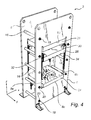
- a press frame module 2 comprises a front plate 4 and a rear plate 6, each having a rectangular plate opening 8 with opposing first and second sides 8a, 8b and opposing third and forth sides 8c, 8d.
- Spacer elements 16 are arranged along the longsides of and between the plates 4, 6, such that they are parallely arranged with aligned plate openings 8, between which a press chamber is formed.
- a press platen 26 is displaceable in the press chamber along the first and second opening sides 8a, 8b.
- the press chamber is delimited in z direction by a stationary lower platen 24 and a stationary upper platen 28, between which the displaceable press platen 26 is displaceable. Press forces are transferred via the upper and lower stationary platens to the front and rear plates 4, 6 and the connecting bars 16.
- a cage structure is formed comprising the spacer elements in form of connecting bars 16, connecting the front and rear plates 4, 6, and guide rails 34, attached to the first and second side openings 8a and 8b for guiding the displaceable press platen.
- the cage structure resists bending and shearing forces on the frame arising when pressing.
- This structure comprises the spacer elements in form of connecting bars 16 for maintaining stability in a yz-plane, the displaceable press platen 26 for maintaining stability in a xy-plane and guide rails 34 for guiding the displaceable press platen and preventing the first and second opening sides from bending.
- X, y and z are coordinates of a three dimensional Cartesian coordinate system as is shown in Figs. 1 , 2 and 4 .
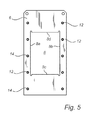
- each plate has two parallel rows of bores 12, with five bores per row.
- the bores 12 are arranged along the longside of the plates.
- Each bore 12 is on the surface to be facing the other plate provided with a surrounding circular guide recess 14 for receiving a connecting bar 16, as is most clearly shown in Figs. 4 and 5 and as will be explained below.
- the number of the bores depends on the size of the press. All bores 12 have the same diameter and all recesses 14 have the same diameter and depth.
- the front plate 4 and the rear plate 6 are identical as regards the size and position of openings and bores. All bore surfaces are finished to achieve a smooth surface impeding formation of cracks.
- the spacer elements comprises ten solid circular connecting bars 16 having a predetermined length. These bars are acting as spacers between the front and the rear plate 4, 6 as well as means for connecting the plates together.
- All bars have a center part 16b with a larger diameter D 2 and end parts 16a with a smaller diameter D 1 .
- the length of the center part 16b is exactly the same for all bars in order to constitue spacers between the front plate 4 and the rear plate 6. Further the smaller diameter end 16a of all bars have the same diameter.
- All the connecting bars 16 are connected to the plates in the same way.
- the smaller diameter ends 16a of a connecting bar 16 are inserted with a tight fit in a pair of aligned bores 12 in the front and the rear plates 4 and 6.
- an end surface of the larger diameter center part 16b of said bar is abutting a recess bottom surface surrounding said bore.
- the recess bottom surface forms a plane surface for receiving the connecting bar 16 in a right-angled fashion.
- the circular recess 14 has a slightly larger diameter than the larger diameter center part 16b.
- each connecting bar 16 is attached to respective plate by means of a screw 18 with a washer 20 fastened in a corresponding threaded hole in the smaller diameter end 16a. There is a clearance 22 between the washer 20 and the plate 4 enabling the plate to be properly biased against the connecting bar 16.
- This construction further provides for a stable, yet easily assembled attachment between connecting bars and plates.
- the displaceable press platen 26 is displaceable along four roller guide rails 34, with two guide rails on each plate, attached to the first and second side opening 8a, 8b in each opening 8, respectively.
- Each rail 34 is carrying a carriage 32 able to glide along the rail.
- Each carriage 32 is in turn attached to a support block 30 at the upper corner of the platen 26 and to a vertical surface of said platen.
- roller guide rails 34 Thanks to the roller guide rails 34 the movement of the displaceable platen 26 is achieved with a high precision.
- the lower platen 24 is a press table protruding into each opening 8 at the third openings sides 8c forming a bottom surface of the press chamber.
- the press table is attached by means of screws 56 to axles which in turn are attached to an anvil table, which could be affected by an anvil cylinder and by means of screws along the third openings sides 8c.
- the upper platen 28 is fixed in essentially the same way and protruding into each opening 8 at the forth openings sides 4d forming a top surface of the press chamber.
- the upper platen 28 is carrying two main cylinders 38 and an additional cylinder 36 of which only a part are visible in Fig. 2 .
- the cylinders are acting on and carrying the displaceable platen 26.
- the additional cylinder is an optional cylinder which could be used for ejection, for example.
- the cylinders are in communication with a highpressure pump via the fluid power conduits 54.
- outer cover plates 42 are arranged between the front and the rear plate 4, 6 outside the connecting bars 12 for preventing unintentional access to the press chamber and for protection in case of bursting conduits.
- inner cover plates 44 are arranged between the front and the rear plate 4, 6 inside the connecting bars 16.
- a door 40 is arranged below the cover plate 42 for allowing access to the press chamber and other interior parts of the press in case of maintenance.
- the press 1 in Fig. 1 is adapted for front feeding but with modified cover plates 42, 44 and door 40 it is easily adapted for side feeding.
- the press frame module according the invention is to be used for a press, such as the press shown in Fig. 1 .
- This press is a hydraulic press 1, though the press frame module 2 could be used for other types of presses, such as mechanical or eccentrical presses.
- the press 1 in Fig. 1 is provided with an operator display 48, an electric cabinet 46 and an inspection balcony 50. Further is shown motor parts 52 and the fluid power conduits 54.
- the method for manufacturing a press frame module for a press comprises first forming the front and the rear plate essentially identical, wherein each plate is provided with an essentially rectangular opening with opposing first and second sides and opposing third and forth sides in a front plate and a rear plate, and perforated with several bores along each longside. Then the spacer elements are formed by cutting a solid circular bar at a predetermined length for preparing a connecting bar for each pair of aligned bores in the front and the rear plates. Each connecting bar is turned to obtain smaller diameter ends for insertion with a tight fit in respective bores. Each bar is inserted in respecive bores such that the plates are parallelly arranged and attached respective plate. Stationary upper and lower platens are attached to the forth and the third side openings, respectively. Further each plate is provided with a pair of parallely arranged and opposing guide rails, and a displaceable press platen is clamped along the guide rails.
- press frame module contains few structural parts it is extremely cost effective to manufacture and simple to assemble. No post treatment is needed.
- the press frame module according the invention is also simple to customize depending on the customer's need.
- the front and rear plates and the connecting bars easily are adapted to different sizes of press tables and press tools without cumbersome reconstruction and machine adjustments at manufacturing of the separate module parts.
- the plates are machined as regarding dimension, size of plate opening, number and dimension of bores and the connecting bars are machined as regarding length and diameters.
Landscapes
- Engineering & Computer Science (AREA)
- Mechanical Engineering (AREA)
- Press Drives And Press Lines (AREA)
Abstract
A press frame module for a press comprises a front plate (4) and a rear plate (6), each having a rectangular plate opening (8) with opposing first and second sides (8a and 8b) and opposing third and forth sides (8c and 8d). Spacer elements (16) are arranged between the plates (4, 6), such that the plates are parallely arranged with aligned plate openings (8) between which a press chamber is formed. A press platen (26), which is arranged in a xy-plane, is displaceable in the press chamber along the first and second opening sides (8a and 8b) in a z direction beween a stationary lower platen (24) and a stationary upper platen (28). Press forces are transferred via the upper and lower stationary platens to the front and rear plates (4 and 6) and the spacer elements (16). A cage structure comprises the spacer elements in form of connecting bars (16), connecting the front and rear plates (4 and 6), and guide rails (34), attached to the first and second side openings (8a and 8b) for guiding the displaceable press platen. Stability is essentially maintained in a yz-plane by the connecting bars (16), in a xy-plane by platens (24, 26, 28) and in a xz-plane by the guide rails (34), wherein x, y and z are coordinates of a three dimensional Cartesian coordinate system.
Description
- The present invention relates to a press frame module for a press comprising a front plate and a rear plate, each having a rectangular plate opening with opposing first and second sides and opposing third and forth sides, wherein spacer elements are arranged between the plates, such that the plates are parallely arranged with aligned plate openings, between which a press chamber is formed, wherein a press platen, which is arranged in a xy-plane, is displaceable in the press chamber along the first and second opening sides in a z direction beween a stationary lower platen and a stationary upper platen, wherein press forces are transferred via the upper and lower stationary platens to the front and rear plates and the spacer elements.
- There are many different constructions of press frames structures for presses. When manufacturing presses welding is often an undesirable operation as it affects the metallic properties and demands special post treatment. This makes assembly at the site of use difficult and requires transport of the often voluminous presses in an assembled form.
-
US 5 027 638 describes a force-resisting structure for a conventionally built press frame. This solid structure is unwelded and comprises metal plates connected and maintained in alignment by a pair of side plates. The plates are connected together with bolts, but the bolts do not participate in resisting the main structural loads. The purpose with this structure is to achieve a structure, where all parts are assembled by means of bolts without welding. This structure is a complex construction with many different parts, such as upper and lower plates with intermediate wedges for transferring forces to load carrying parts. Further it does not allow side feeding of objects to be pressed. - An object of the present invention is to provide a press frame module which is easy and cost effective to produce and mount, and which provides for exactly guided and controlled movements of a press platen. A further object is to achieve a versatile press frame which allows front feeding and side feeding. An additional object is to provide a press frame which is easy to reconstruct and manufacture in different dimensions and for different power sources. Another object of the present invention is to provide a method for manufacturing said press, said method distinguishes itself by being quite simple and yet versatile.
- These objects are achieved as regards the press frame module by means of a press frame module of the above mentioned kind which is characterized by a cage structure comprising the spacer elements in form of connecting bars, connecting the front and rear plates, and guide rails, attached to the first and second side openings for guiding the displaceable press platen, such that stability is essentially maintained in a yz-plane by the connecting bars, in a xy-plane by platens and in a xz-plane by the guide rails, wherein x, y and z are coordinates of a three dimensional Cartesian coordinate system.
- It proves that the connecting bars i combination with the press platens and the guide rails provide for a suffient stability in a press frame.
- Each spacer element comprises several connecting bars, wherein the front and the rear plate have aligned pairs of bores, wherein the two ends of each bar is received in a pair of bores and attached to the plates.
- Preferably each connecting bar is a solid circular bar with a larger diameter center part and smaller diameter ends, wherein each bore has a diameter of essentially the same diameter as the smaller diameter ends for receiving each end with a tight fit, and wherein each bore, on the surface facing the opposite plate, has a surrounding circular recess forming a plane surface for receiving a connecting bar in a right-angled fashion.
- Hence each bar is easily machined and preferably attached by means of screws, though it is also possible to use a key or cotter.
- With all bores machined exactly the same and with identical connecting bars this construction provides for a simple assembly with exactly spaced apart plates. The recesses further improves the stability of the press frame module.
- These objects are achieved as regards the method for manufacturing a press frame by a) forming an essentially rectangular opening with opposing first and second sides and opposing third and forth sides in a front plate, b) drilling several bores in the front plate along each longside, c) performing the steps according to a) and b) on a rear plate such that the opening and bores in the front plate are aligned with the opening and bores in the rear plate, d) providing a solid circular bar having a predetermined length for preparing a connecting bar for each pair of aligned bores in the front and the rear plates, wherein each connecting bar has smaller diameter ends for insertion with a tight fit in respective bores, e) inserting each bar in respecive bores such that the plates are parallelly arranged, f) attaching each bar to respective plate, g) attaching a lower stationary platen to the third side openings and an upper stationary platen to the forth side openings, h) providing each plate with a pair of parallely arranged and opposing guide rails, and i) clamping a platen for displacement along the guide rails.
- This method provides for achieving a frame structure which to a great extent facilitates manufacturing of the separate parts as well mounting of said parts as the frame structure comprises few different structural elements without need of welding. The method enables facilitate prefabrication and post assembly at site which in turn reduces transport costs.
- Further objects and features of the present invention will be apparent from the description and the claims.
- The invention will now be described in more detail with reference to the appended drawings in which:
-
Fig. 1 is a perspective view showing a press with a press frame module according the invention. -
Fig. 2 is a perspective cross section along III-III inFig. 1 . -
Fig. 3 is a cross section in an enlarged scale showing a connecting bar inserted in a plate. -
Fig. 4 is a perspective view of a press frame module according the invention. -
Fig. 5 is a front view of a rear plate in the press frame shown inFig. 1 . - A
press frame module 2 according the invention comprises afront plate 4 and a rear plate 6, each having a rectangular plate opening 8 with opposing first andsecond sides sides Spacer elements 16 are arranged along the longsides of and between theplates 4, 6, such that they are parallely arranged with alignedplate openings 8, between which a press chamber is formed. Apress platen 26 is displaceable in the press chamber along the first and second openingsides - The press chamber is delimited in z direction by a stationary
lower platen 24 and a stationaryupper platen 28, between which thedisplaceable press platen 26 is displaceable. Press forces are transferred via the upper and lower stationary platens to the front andrear plates 4, 6 and the connectingbars 16. Hence a cage structure is formed comprising the spacer elements in form of connectingbars 16, connecting the front andrear plates 4, 6, andguide rails 34, attached to the first andsecond side openings - The cage structure resists bending and shearing forces on the frame arising when pressing. This structure comprises the spacer elements in form of connecting
bars 16 for maintaining stability in a yz-plane, thedisplaceable press platen 26 for maintaining stability in a xy-plane andguide rails 34 for guiding the displaceable press platen and preventing the first and second opening sides from bending. X, y and z are coordinates of a three dimensional Cartesian coordinate system as is shown inFigs. 1 ,2 and4 . - In the embodiment shown in the drawings each plate has two parallel rows of
bores 12, with five bores per row. Thebores 12 are arranged along the longside of the plates. Eachbore 12 is on the surface to be facing the other plate provided with a surrounding circular guide recess 14 for receiving a connectingbar 16, as is most clearly shown inFigs. 4 and5 and as will be explained below. The number of the bores depends on the size of the press. Allbores 12 have the same diameter and allrecesses 14 have the same diameter and depth. Thefront plate 4 and the rear plate 6 are identical as regards the size and position of openings and bores. All bore surfaces are finished to achieve a smooth surface impeding formation of cracks. - The spacer elements comprises ten solid circular connecting
bars 16 having a predetermined length. These bars are acting as spacers between the front and therear plate 4, 6 as well as means for connecting the plates together. - All bars have a
center part 16b with a larger diameter D2 andend parts 16a with a smaller diameter D1. The length of thecenter part 16b is exactly the same for all bars in order to constitue spacers between thefront plate 4 and the rear plate 6. Further thesmaller diameter end 16a of all bars have the same diameter. - All the connecting
bars 16 are connected to the plates in the same way. Thesmaller diameter ends 16a of a connectingbar 16 are inserted with a tight fit in a pair of alignedbores 12 in the front and therear plates 4 and 6. When asmaller diameter end 16a of a bar is inserted in a bore, an end surface of the largerdiameter center part 16b of said bar is abutting a recess bottom surface surrounding said bore. The recess bottom surface forms a plane surface for receiving the connectingbar 16 in a right-angled fashion. Thecircular recess 14 has a slightly larger diameter than the largerdiameter center part 16b. - With this construction the plates will be parallely arranged at a exact fixed distance from each other with the bars in a right angle in relation to the plates. Each connecting
bar 16 is attached to respective plate by means of ascrew 18 with awasher 20 fastened in a corresponding threaded hole in thesmaller diameter end 16a. There is aclearance 22 between thewasher 20 and theplate 4 enabling the plate to be properly biased against the connectingbar 16. This construction further provides for a stable, yet easily assembled attachment between connecting bars and plates. - The
displaceable press platen 26 is displaceable along fourroller guide rails 34, with two guide rails on each plate, attached to the first and second side opening 8a, 8b in eachopening 8, respectively. Eachrail 34 is carrying acarriage 32 able to glide along the rail. Eachcarriage 32 is in turn attached to asupport block 30 at the upper corner of theplaten 26 and to a vertical surface of said platen. - Thanks to the
roller guide rails 34 the movement of thedisplaceable platen 26 is achieved with a high precision. - The
lower platen 24 is a press table protruding into eachopening 8 at the third openings sides 8c forming a bottom surface of the press chamber. The press table is attached by means ofscrews 56 to axles which in turn are attached to an anvil table, which could be affected by an anvil cylinder and by means of screws along the third openings sides 8c. - The
upper platen 28 is fixed in essentially the same way and protruding into eachopening 8 at the forth openings sides 4d forming a top surface of the press chamber. Theupper platen 28 is carrying twomain cylinders 38 and anadditional cylinder 36 of which only a part are visible inFig. 2 . The cylinders are acting on and carrying thedisplaceable platen 26. - The additional cylinder is an optional cylinder which could be used for ejection, for example. The cylinders are in communication with a highpressure pump via the
fluid power conduits 54. - As seen in
Fig. 1 outer cover plates 42 are arranged between the front and therear plate 4, 6 outside the connectingbars 12 for preventing unintentional access to the press chamber and for protection in case of bursting conduits. - Further,
inner cover plates 44 are arranged between the front and therear plate 4, 6 inside the connecting bars 16. Adoor 40 is arranged below thecover plate 42 for allowing access to the press chamber and other interior parts of the press in case of maintenance. - The
press 1 inFig. 1 is adapted for front feeding but with modifiedcover plates door 40 it is easily adapted for side feeding. - The press frame module according the invention is to be used for a press, such as the press shown in
Fig. 1 . This press is ahydraulic press 1, though thepress frame module 2 could be used for other types of presses, such as mechanical or eccentrical presses. Thepress 1 inFig. 1 is provided with anoperator display 48, anelectric cabinet 46 and aninspection balcony 50. Further is shownmotor parts 52 and thefluid power conduits 54. - The method for manufacturing a press frame module for a press comprises first forming the front and the rear plate essentially identical, wherein each plate is provided with an essentially rectangular opening with opposing first and second sides and opposing third and forth sides in a front plate and a rear plate, and perforated with several bores along each longside. Then the spacer elements are formed by cutting a solid circular bar at a predetermined length for preparing a connecting bar for each pair of aligned bores in the front and the rear plates. Each connecting bar is turned to obtain smaller diameter ends for insertion with a tight fit in respective bores. Each bar is inserted in respecive bores such that the plates are parallelly arranged and attached respective plate. Stationary upper and lower platens are attached to the forth and the third side openings, respectively. Further each plate is provided with a pair of parallely arranged and opposing guide rails, and a displaceable press platen is clamped along the guide rails.
- As the press frame module contains few structural parts it is extremely cost effective to manufacture and simple to assemble. No post treatment is needed.
- The press frame module according the invention is also simple to customize depending on the customer's need. The front and rear plates and the connecting bars easily are adapted to different sizes of press tables and press tools without cumbersome reconstruction and machine adjustments at manufacturing of the separate module parts. Depending on the chosen size of press frame the plates are machined as regarding dimension, size of plate opening, number and dimension of bores and the connecting bars are machined as regarding length and diameters.
Claims (4)
- Press frame module for a press comprising
a front plate (4) and a rear plate (6), each having a rectangular plate opening (8) with opposing first and second sides (8a and 8b) and opposing third and forth sides (8c and 8d), wherein spacer elements (16) are arranged between the plates (4, 6), such that the plates are parallely arranged with aligned plate openings (8), between which a press chamber is formed, wherein a press platen (26), which is arranged in a xy-plane, is displaceable in the press chamber along the first and second opening sides (8a and 8b) in a z direction beween a stationary lower platen (24) and a stationary upper platen (28), wherein press forces are transferred via the upper and lower stationary platens to the front and rear plates (4 and 6) and the spacer elements (16),
characterized by a cage structure comprising the spacer elements in form of connecting bars (16), connecting the front and rear plates (4 and 6), and guide rails (34), attached to the first and second side openings (8a and 8b) for guiding the displaceable press platen,
such that stability is essentially maintained in a yz-plane by the connecting bars (16), in a xy-plane by platens (24, 26, 28) and in a xz-plane by the guide rails (34), wherein x, y and z are coordinates of a three dimensional Cartesian coordinate system. - Press frame module according to claim 1, wherein the front and the rear plates (4 and 6) have aligned pairs of bores (12), wherein the two ends (16a) of each bar is received in a pair of bores (12) and attached to the plates (4, 6).
- Press frame module according to claim 2, wherein each connecting bar (16) is a solid circular bar with a larger diameter center part (16b) and smaller diameter ends (16a), wherein each bore (12) has a diameter of essentially the same diameter as the smaller diameter ends (16a) for receiving each end with a tight fit, and wherein each bore (12), on the surface facing the opposite plate, has a surrounding circular recess (14) forming a plane surface for receiving a connecting bar (16) in a right-angled fashion.
- Method for manufacturing press frame module for a press comprising the steps ofa) forming an essentially rectangular opening (8) with opposing first and second sides (8a and 8b) and opposing third and forth sides (8c and 8d) in a front plate (4),b) drilling several bores (12) in the front plate along each plate longside,c) performing the steps according to a) and b) on a rear plate (6) such that the opening (8) and bores (12) in the front plate (4) are aligned with the opening (8) and bores (12) in the rear plate,d) providing a solid circular bar (12) having a predetermined length for preparing a connecting bar for each pair of aligned bores (12) in the front and the rear plates (4 and 6), wherein each connecting bar has smaller diameter ends (16a) for insertion with a tight fit in respective bores (12),e) inserting each bar (12) in respecive bores such that the plates are parallelly arranged,f) attaching each bar (12) to respective plate (4, 6),g) attaching a lower stationary platen (24) to the third side openings (8c) and an upper stationary platen 28) to the forth side openings (8a)h) providing each plate (4, 6) with a pair of parallely arranged and opposing guide rails (34), andi) clamping a platen (26) for displacement along the guide rails (34).
Priority Applications (2)
| Application Number | Priority Date | Filing Date | Title |
|---|---|---|---|
| EP08159699A EP2141006A1 (en) | 2008-07-04 | 2008-07-04 | Press frame module |
| PCT/EP2009/058410 WO2010000837A1 (en) | 2008-07-04 | 2009-07-03 | Press frame module |
Applications Claiming Priority (1)
| Application Number | Priority Date | Filing Date | Title |
|---|---|---|---|
| EP08159699A EP2141006A1 (en) | 2008-07-04 | 2008-07-04 | Press frame module |
Publications (1)
| Publication Number | Publication Date |
|---|---|
| EP2141006A1 true EP2141006A1 (en) | 2010-01-06 |
Family
ID=39739434
Family Applications (1)
| Application Number | Title | Priority Date | Filing Date |
|---|---|---|---|
| EP08159699A Withdrawn EP2141006A1 (en) | 2008-07-04 | 2008-07-04 | Press frame module |
Country Status (2)
| Country | Link |
|---|---|
| EP (1) | EP2141006A1 (en) |
| WO (1) | WO2010000837A1 (en) |
Cited By (4)
| Publication number | Priority date | Publication date | Assignee | Title |
|---|---|---|---|---|
| EP2527114A1 (en) * | 2011-05-27 | 2012-11-28 | Siempelkamp Maschinen- und Anlagenbau GmbH & Co. KG | Continuous press |
| RU180040U1 (en) * | 2017-08-25 | 2018-06-01 | Федеральное государственное бюджетное образовательное учреждение высшего образования "Московский государственный технологический университет "СТАНКИН" (ФГБОУ ВО "МГТУ "СТАНКИН") | Bed press |
| US10011041B2 (en) | 2015-05-15 | 2018-07-03 | Usnr, Llc | Modular press |
| US20220314569A1 (en) * | 2021-04-02 | 2022-10-06 | Joseph Gambino | Retrofit systems for converting manual presses to automated presses |
Families Citing this family (1)
| Publication number | Priority date | Publication date | Assignee | Title |
|---|---|---|---|---|
| CZ307557B6 (en) | 2010-10-07 | 2018-12-05 | Tescan Orsay Holding, A.S. | A scintillation detection unit for detecting backscattered electrons for electron or ion microscopes |
Citations (9)
| Publication number | Priority date | Publication date | Assignee | Title |
|---|---|---|---|---|
| US3523443A (en) * | 1967-08-30 | 1970-08-11 | Cameron Iron Works Inc | Hydraulic press |
| DE1752352A1 (en) * | 1968-05-14 | 1971-05-19 | Eugen Siempelkamp | Frame press |
| GB2235410A (en) * | 1989-08-29 | 1991-03-06 | Dorstener Maschf Ag | Hydraulic press |
| US5027638A (en) | 1990-06-22 | 1991-07-02 | Friestad Roland W | Force-resisting structure |
| DE19607257A1 (en) * | 1996-02-27 | 1997-08-28 | Hydrap Pressen Maschinenbau | Hydraulic pressing machine for shaping sheet metal parts |
| EP0916461A1 (en) * | 1997-11-17 | 1999-05-19 | Sama S.R.L. | Pressing device |
| JPH11267897A (en) * | 1998-03-23 | 1999-10-05 | Senyo Kk | Hydraulic press |
| DE19949473C1 (en) * | 1999-10-14 | 2000-10-05 | Joachim Utsch | Hydraulic bench press to emboss vehicle number plates has a frame composed of a number of vertical and parallel spaced frame plates locked together by bolts in a lightweight and inexpensive appts |
| DE102004032259A1 (en) * | 2004-07-03 | 2006-01-26 | Siempelkamp Maschinen- Und Anlagenbau Gmbh & Co. Kg | Press, in particular multi-daylight press |
Family Cites Families (4)
| Publication number | Priority date | Publication date | Assignee | Title |
|---|---|---|---|---|
| DE471188C (en) * | 1929-02-08 | Fried Krupp Grusonwerk Akt Ges | Press frame with fixed and rigidly interconnected special bars | |
| CH290080A (en) * | 1951-12-29 | 1953-04-15 | Isler Fritz | Stand. |
| DE2023334A1 (en) * | 1970-05-13 | 1971-12-02 | Lohrengel, Heinz, Dipl.-Ing., 61O2Pfungstadt | Press frame |
| JPS50110166A (en) * | 1974-02-09 | 1975-08-29 |
-
2008
- 2008-07-04 EP EP08159699A patent/EP2141006A1/en not_active Withdrawn
-
2009
- 2009-07-03 WO PCT/EP2009/058410 patent/WO2010000837A1/en not_active Ceased
Patent Citations (9)
| Publication number | Priority date | Publication date | Assignee | Title |
|---|---|---|---|---|
| US3523443A (en) * | 1967-08-30 | 1970-08-11 | Cameron Iron Works Inc | Hydraulic press |
| DE1752352A1 (en) * | 1968-05-14 | 1971-05-19 | Eugen Siempelkamp | Frame press |
| GB2235410A (en) * | 1989-08-29 | 1991-03-06 | Dorstener Maschf Ag | Hydraulic press |
| US5027638A (en) | 1990-06-22 | 1991-07-02 | Friestad Roland W | Force-resisting structure |
| DE19607257A1 (en) * | 1996-02-27 | 1997-08-28 | Hydrap Pressen Maschinenbau | Hydraulic pressing machine for shaping sheet metal parts |
| EP0916461A1 (en) * | 1997-11-17 | 1999-05-19 | Sama S.R.L. | Pressing device |
| JPH11267897A (en) * | 1998-03-23 | 1999-10-05 | Senyo Kk | Hydraulic press |
| DE19949473C1 (en) * | 1999-10-14 | 2000-10-05 | Joachim Utsch | Hydraulic bench press to emboss vehicle number plates has a frame composed of a number of vertical and parallel spaced frame plates locked together by bolts in a lightweight and inexpensive appts |
| DE102004032259A1 (en) * | 2004-07-03 | 2006-01-26 | Siempelkamp Maschinen- Und Anlagenbau Gmbh & Co. Kg | Press, in particular multi-daylight press |
Cited By (8)
| Publication number | Priority date | Publication date | Assignee | Title |
|---|---|---|---|---|
| EP2527114A1 (en) * | 2011-05-27 | 2012-11-28 | Siempelkamp Maschinen- und Anlagenbau GmbH & Co. KG | Continuous press |
| WO2012163729A1 (en) * | 2011-05-27 | 2012-12-06 | Siempelkamp Maschinen- Und Anlagenbau Gmbh & Co. Kg | Continuous press |
| US10011041B2 (en) | 2015-05-15 | 2018-07-03 | Usnr, Llc | Modular press |
| EP3297826A4 (en) * | 2015-05-15 | 2019-05-29 | Usnr, Llc | MODULAR PRESS |
| US11192275B2 (en) | 2015-05-15 | 2021-12-07 | Usnr, Llc | Modular press |
| RU180040U1 (en) * | 2017-08-25 | 2018-06-01 | Федеральное государственное бюджетное образовательное учреждение высшего образования "Московский государственный технологический университет "СТАНКИН" (ФГБОУ ВО "МГТУ "СТАНКИН") | Bed press |
| US20220314569A1 (en) * | 2021-04-02 | 2022-10-06 | Joseph Gambino | Retrofit systems for converting manual presses to automated presses |
| US11529784B2 (en) * | 2021-04-02 | 2022-12-20 | Rogue Fabrication, LLC | Retrofit systems for converting manual presses to automated presses |
Also Published As
| Publication number | Publication date |
|---|---|
| WO2010000837A1 (en) | 2010-01-07 |
Similar Documents
| Publication | Publication Date | Title |
|---|---|---|
| DE102018102314B4 (en) | Matrix arrangement for an embossing press | |
| AT390598B (en) | MACHINE TABLE IN MODULAR DESIGN FOR PRODUCTION EQUIPMENT | |
| WO2010000837A1 (en) | Press frame module | |
| EP2210681A2 (en) | Bending press with a multi-part press bar | |
| EP2762271A1 (en) | Modular system for holding operating modules of a processing unit and processing installation | |
| KR101056469B1 (en) | Bus Bar Processing Equipment | |
| EP1242212B1 (en) | Machine tool | |
| CN217860063U (en) | Brace is used in movable cutting | |
| DE10229341A1 (en) | processing plant | |
| CN210881054U (en) | Digital servo hydraulic press | |
| EP2509724B1 (en) | Method for forming the body of a press brake, and a press brake | |
| DE10155632C1 (en) | Frame for switch cabinet has vertical support secured to corner of baseplate via socket plate with 2 right angle bearing surfaces | |
| US4192209A (en) | Hydraulically actuated cutting and punching assembly | |
| CN212793851U (en) | Assembling device for stainless steel cabinet frame | |
| CN210676550U (en) | Multi-station punching equipment for cold roll forming | |
| KR100377899B1 (en) | a piercing machine for manufacturing steel door | |
| DE102012102526B4 (en) | C-frame press | |
| EP1867469B1 (en) | Stamping and forming machine | |
| CN217680201U (en) | Combined building material decorative plate | |
| CN210358737U (en) | Adjustable punching mechanism for punching machine | |
| DE2608159A1 (en) | Sheet and strip folding press - has forming tool and offset carrier with right angled seating faces and tapered dowels | |
| CN217291322U (en) | Firm type machining center stand | |
| CN213288991U (en) | Square steel plate flame cutting and trimming device | |
| CN212577285U (en) | Support frame for punching angle steel | |
| CN218906383U (en) | Convenient-to-detach packer |
Legal Events
| Date | Code | Title | Description |
|---|---|---|---|
| PUAI | Public reference made under article 153(3) epc to a published international application that has entered the european phase |
Free format text: ORIGINAL CODE: 0009012 |
|
| AK | Designated contracting states |
Kind code of ref document: A1 Designated state(s): AT BE BG CH CY CZ DE DK EE ES FI FR GB GR HR HU IE IS IT LI LT LU LV MC MT NL NO PL PT RO SE SI SK TR |
|
| AX | Request for extension of the european patent |
Extension state: AL BA MK RS |
|
| AKY | No designation fees paid | ||
| REG | Reference to a national code |
Ref country code: DE Ref legal event code: 8566 |
|
| STAA | Information on the status of an ep patent application or granted ep patent |
Free format text: STATUS: THE APPLICATION IS DEEMED TO BE WITHDRAWN |
|
| 18D | Application deemed to be withdrawn |
Effective date: 20100707 |