EP2140961A1 - Machine with UV Illumination - Google Patents
Machine with UV Illumination Download PDFInfo
- Publication number
- EP2140961A1 EP2140961A1 EP09162848A EP09162848A EP2140961A1 EP 2140961 A1 EP2140961 A1 EP 2140961A1 EP 09162848 A EP09162848 A EP 09162848A EP 09162848 A EP09162848 A EP 09162848A EP 2140961 A1 EP2140961 A1 EP 2140961A1
- Authority
- EP
- European Patent Office
- Prior art keywords
- machine
- light
- light source
- workpiece
- markings
- Prior art date
- Legal status (The legal status is an assumption and is not a legal conclusion. Google has not performed a legal analysis and makes no representation as to the accuracy of the status listed.)
- Withdrawn
Links
- 238000005286 illumination Methods 0.000 title description 2
- 230000007246 mechanism Effects 0.000 claims abstract description 16
- 230000003213 activating effect Effects 0.000 claims abstract description 4
- 238000009958 sewing Methods 0.000 claims description 16
- 238000000034 method Methods 0.000 claims description 7
- 238000005520 cutting process Methods 0.000 description 11
- 239000000463 material Substances 0.000 description 10
- 238000005304 joining Methods 0.000 description 4
- 239000004744 fabric Substances 0.000 description 3
- 239000000428 dust Substances 0.000 description 2
- 230000000694 effects Effects 0.000 description 2
- 238000000227 grinding Methods 0.000 description 2
- 239000010985 leather Substances 0.000 description 2
- 238000012986 modification Methods 0.000 description 2
- 230000004048 modification Effects 0.000 description 2
- 230000005855 radiation Effects 0.000 description 2
- OKTJSMMVPCPJKN-UHFFFAOYSA-N Carbon Chemical compound [C] OKTJSMMVPCPJKN-UHFFFAOYSA-N 0.000 description 1
- 230000008901 benefit Effects 0.000 description 1
- 239000003610 charcoal Substances 0.000 description 1
- 230000000295 complement effect Effects 0.000 description 1
- 238000005553 drilling Methods 0.000 description 1
- 229910002804 graphite Inorganic materials 0.000 description 1
- 239000010439 graphite Substances 0.000 description 1
- 239000004519 grease Substances 0.000 description 1
- 230000008676 import Effects 0.000 description 1
- 239000003550 marker Substances 0.000 description 1
- 239000002184 metal Substances 0.000 description 1
- 239000004033 plastic Substances 0.000 description 1
- 230000004044 response Effects 0.000 description 1
- 238000005096 rolling process Methods 0.000 description 1
- 239000004753 textile Substances 0.000 description 1
- 239000002023 wood Substances 0.000 description 1
Images



Classifications
-
- B—PERFORMING OPERATIONS; TRANSPORTING
- B23—MACHINE TOOLS; METAL-WORKING NOT OTHERWISE PROVIDED FOR
- B23D—PLANING; SLOTTING; SHEARING; BROACHING; SAWING; FILING; SCRAPING; LIKE OPERATIONS FOR WORKING METAL BY REMOVING MATERIAL, NOT OTHERWISE PROVIDED FOR
- B23D59/00—Accessories specially designed for sawing machines or sawing devices
- B23D59/001—Measuring or control devices, e.g. for automatic control of work feed pressure on band saw blade
- B23D59/002—Measuring or control devices, e.g. for automatic control of work feed pressure on band saw blade for the position of the saw blade
-
- B—PERFORMING OPERATIONS; TRANSPORTING
- B23—MACHINE TOOLS; METAL-WORKING NOT OTHERWISE PROVIDED FOR
- B23D—PLANING; SLOTTING; SHEARING; BROACHING; SAWING; FILING; SCRAPING; LIKE OPERATIONS FOR WORKING METAL BY REMOVING MATERIAL, NOT OTHERWISE PROVIDED FOR
- B23D49/00—Machines or devices for sawing with straight reciprocating saw blades, e.g. hacksaws
- B23D49/10—Hand-held or hand-operated sawing devices with straight saw blades
- B23D49/16—Hand-held or hand-operated sawing devices with straight saw blades actuated by electric or magnetic power or prime movers
- B23D49/162—Pad sawing devices
-
- D—TEXTILES; PAPER
- D05—SEWING; EMBROIDERING; TUFTING
- D05B—SEWING
- D05B79/00—Incorporations or adaptations of lighting equipment
Definitions
- the present teachings relate to machines and more particularly relate to a machine having a UV light source for illuminating markings on a workpiece.
- Machines are provided in many varieties, such as handheld power tools for example that can be used to manipulate (such as cut) a workpiece (i.e., a jigsaw, rotary tool, circular saw, grinder, etc.).
- Other machines can include sewing machines or other machines that are used to manipulate a workpiece (i.e., sew or employ stitching with a thread to a material such as fabric, or leather for example).
- manipulating a workpiece can include joining multiple workpieces together.
- a user may mark onto a workpiece with a writing instrument a desired working path. The working path can then be followed by the working member (i.e., saw blade, bit, needle, etc.).
- a machine can include a machine housing and a drive mechanism disposed in the machine housing and driving an output member.
- An input member can be associated with the machine housing for activating the drive mechanism.
- a working member can be driven by the output member.
- a light source can be coupled to the machine housing that projects UV light onto an area proximate to the working member.
- the light source can comprise a UV light source.
- the light source can collectively define a light emitting device and a filter.
- the filter can allow black light to pass therethrough.
- the light emitting device can comprise an incandescent bulb, a light emitting diode, or a fluorescent bulb according to various examples.
- a writing instrument can be operable to place markings onto a workpiece.
- the markings can correspond to a working pattern.
- the UV light can illuminate the working pattern relative to the area proximate to the working member.
- the light source according to one example can be disposed on the machine housing generally proximate to the working member.
- the light source can be powered by a power source that is internal to the machine housing.
- the light source can be powered by a common power source as the drive mechanism.
- the machine can further comprise a switch that selectively electrically connects the light source to the common power source.
- the light source can be disposed in a light housing that is portable and comprises an internal power source.
- the machine can comprise a sewing machine.
- the working member can comprise a needle.
- the input member can comprise a foot pedal.
- the machine can comprise one of a rotary tool, a grinder, a circular saw and a jigsaw.
- the drive mechanism can be hand driven.
- a method of manipulating a workpiece with a machine can include marking a pattern onto the workpiece with a writing instrument.
- a UV light source associated with the workpiece can be activated.
- the UV light source can emit light that makes the markings of the pattern appear optically brighter relative to the surrounding areas of the workpiece in range of the emitted light.
- the workpiece can be manipulated with a working member on the machine while directing the working member substantially along the markings.
- the working member can include a needle.
- Manipulating the workpiece can include repeatedly passing the needle through the workpiece to secure a flexible member carried by the needle substantially along the markings.
- the power tool 10 can generally comprise a housing 12 containing a motor 14.
- the housing 12 can generally comprise a main body 16, a front portion 18, a rear portion 20, an upper portion 22 and a lower portion 24.
- the upper portion 22 can define a handle 30 having a trigger assembly 32.
- a power switch 34 can be provided on the upper portion 22 of the tool 10.
- the motor 14 When activated by the trigger assembly 32, the motor 14 can provide a reciprocating and/or pendulum motion to an output member, such as a cutting blade holder 40, on an end of a reciprocating shaft to drive a cutting blade 42.
- a control member 44 can be provided on the main body 16 of the housing 12. In one example, the control member 44 can control a rate of reciprocation and/or a magnitude of a pendulum motion of the cutting blade 42.
- handheld power tool 10 is represented in the figures as a jigsaw
- teachings of the present disclosure are also applicable to other handheld power tools, such as, but not limited to, circulating saws, reciprocating saws, scroll saws, miter saw, band saws, portable band saws, rotary tools, cut-out tools, drills, routers, grinders, or any other tool in which an illumination of an area or path would assist the user in seeing a cutting or working line.
- the present teachings are applicable to machines in general or any device where following a path is recommended during use.
- a shoe member 50 can be coupled to the lower portion 24 of the housing 12. During use, a bottom surface 54 of the shoe member 50 can abut a workpiece 56, which can be wood, plastic, metal, other suitable materials and one or more combinations thereof and can be in the form of pipe, sheet material, stock material, other suitable forms and/or materials and one or more combinations thereof.
- the handheld power tool 10 can further comprise a rolling blade guide 60 that can guide the blade 42 during reciprocating motion.
- a dust blower 62 can be disposed in the housing 12, such as near the lower portion 24. The dust blower 62 can be configured to blow air onto the workpiece 56 in a direction generally proximate to the cutting area of the blade 42 to disperse debris from the workpiece 56 at an area adjacent to the blade 42.
- the handheld power tool 10 can further comprise a light source 70 having a light outlet 72.
- the light source 70 can be disposed generally on the front portion 18 of the housing 12.
- the light source 70 according to the present teachings can comprise an ultraviolet (UV) light.
- the UV light can be in the form of a bulb, a light-emitting diode (LED), or other forms.
- the UV light source 70 can include a black light.
- the light source 70 can be configured to shine light out of the light outlet 72 and onto a work area 76 of the workpiece 56.
- the light source 70 can emit a generally wide beam 80 of UV light onto the work area 76 of the workpiece 56.
- the light source 70 can emit the beam 80 onto the work area 76 of the workpiece 56 to illuminate markings drawn by the user onto the workpiece 56 that identify an area of interest such as a desired cut pattern for example.
- a writing instrument 84 can be provided for drawing markings 86 onto the workpiece 56.
- a writing instrument 84 can comprise any writing tool that can mark a workpiece, such as a highlighter, a pencil, a pen, a marker, or other writing tool.
- the pencil can comprise a graphite pencil, a charcoal pencil, a crayon, a grease pencil, or other variety of pencil.
- the highlighter can comprise any color, such as yellow for example. In this way, a user can draw the markings 86 onto the workpiece 56 to identify a desired line of cut.
- the light source 70 can be adapted to transmit UV light onto the surrounding work area 76 rather than simply project a line of light, such as provided by a laser, for example. By shining on an area, the UV light can shine on markings that are within the work area 76.
- the handheld power tool 10 is shown cutting the workpiece 56 along the marking 86.
- the beam 80 of the light source 70 illuminates the markings 86 by way of the UV light.
- the UV light can transmit radiation prompting visible effects of fluorescence and phosphorescence. More specifically, the beam 80 of UV light illuminates the markings 86 relative to the surrounding work area 76 to make the markings easily visible by the user.
- the UV light may be projected onto the work area 76 of the workpiece 56, the work area 76 does not necessarily illuminate as would be the case with a conventional incandescent (or other) light bulb.
- the UV light will cause the markings 86 to illuminate significantly relative to the remainder of the work area 76 (i.e., areas without the markings 86 but within the work area 76). Also, as can be appreciated, the beam 80 of UV light can effectively illuminate a curved path of the markings 86, such that a user can effectively anticipate movements of the tool 10 as the user cuts through the workpiece 56.
- the power tool 110 can generally define a tool housing 112. While not specifically shown in Fig. 4 , the power tool 110 can generally take the form of the handheld power tool 10 described above with respect to Fig. 1 . It is appreciated that while specific components shown in the power tool 10 of Fig. 1 have been omitted in the illustration of the power tool 110 of Fig. 4 that they are simply omitted for clarity purposes.
- the power tool 110 can comprise a light source 170 having a light outlet 172.
- the light source 170 having the light outlet 172 can be generally provided as part of a light housing 174.
- the light source 170 can be configured to emit UV light as described above with respect to the light source 170.
- the power tool 110 can further comprise a power distributor/converter that can convert alternating current (AC) from a power cord 178 into usable power for the power tool 110.
- the power tool 110 can include an on/off switch 180.
- the on/off switch 180 can be turned to an "on" position to communicate electrical power from the power distributor/converter 176 to the light source 170.
- the light source 170 can be powered by the same source as other components (i.e., the motor) of the power tool 110.
- the on/off switch 180 By turning the on/off switch 180 to an "off" position, a user can disable power communication to the light source 170 when the light source 170 is not needed.
- the power tool 110 has been shown with a standard AC power cord 178, the power tool 110 can alternatively be powered by an onboard power source, such as batteries, for example.
- the power tool 210 can be configured similar to the power tool 10 illustrated in Fig. 1 . In this way, features shown and described above with respect to the power tool 10 (or machines 310, 410) can likewise be included on the power tool 210 of Fig. 5 .
- the power tool 210 can include a receiving member 220 that can selectively couple with an attachment member 224 defined on a light housing 274 of the light source 270.
- the light source 270 can be configured to transmit UV light, such as described above in relation to the power tools 10 and 110 described above.
- the light source 270 can be a self-contained light source having an onboard power supply 276 (such as batteries for example) electrically coupled to an on/off switch 280 provided on the light housing 274.
- the light source 270 can define a light outlet 272 for emitting UV light onto a workpiece.
- the receiving member 220 and attachment member 224 can take various forms.
- the receiving member 220 and the attachment member 224 can comprise a combination of fasteners that are configured to selectively mate with complementary features for securing the light source 270 to the tool 210.
- the receiving member 220 and the attachment member 224 can take on other forms, such as, but not limited to, magnets.
- the receiving member 220 can be arranged such that when the attachment member 224 is coupled with the receiving member 220, the light outlet 272 is aligned for emitting the UV light onto the work area (i.e., work area 76, Fig. 1 ).
- the light outlet 272 can be adjustable, such that a user can alter the direction of emitted light from the light outlet 272. It is also contemplated that the light source 70 ( Fig. 1 ) and the light source 170 ( Fig. 4 ) can also include an adjustable light outlet 72 and 172, respectively, such that a user can adjust the direction that the light is emitted onto in the work area 76 of the workpiece 56.
- the machine 310 can generally comprise a machine housing 312 containing a drive mechanism 314.
- An input member 332 can be coupled to the housing 312.
- An output member 340 can be driven by the drive mechanism 314 in response to an input from the input member 332 and provide a resultant motion onto a working member 342.
- the machine 310 can further comprise a light source 370 operable to shine a light out of the light source 370 and onto a work area 376 of a workpiece 356.
- the light source 370 can emit a generally wide beam 380 of UV light onto the work area 376 of the workpiece 356.
- the machine 310 can comprise any machine used to perform a task on a workpiece. More particularly, the machine 310 can comprise any machine used to manipulate (i.e., cut, drill, grind, join, sew, weld, etc.) a workpiece 356 (including multiple workpieces concurrently) where an operator may follow a path identified on the workpiece 356 (markings, etc) with the working member 342.
- the working member can include, for example, a blade, a bit, a grinding wheel, a needle, other cutting instruments or joining instruments, and others.
- the drive mechanism 314 can comprise a motor such as described above with respect to the motor 14.
- the drive mechanism 314 can also comprise non-motorized devices such as hand operated devices or other apparatus that can impart motion onto an output member 340.
- the sewing machine 410 can generally comprise a sewing machine housing 412 having a drive mechanism 414 in the form of a motor.
- An input member 432 can be coupled to the sewing machine 410 for providing a signal to the drive mechanism 414.
- the input member 432 according to one example can comprise a foot pedal.
- the drive mechanism 414 can drive an output member 440 such as a needle holder.
- the output member 440 can selectively retain a working member such as a needle 442.
- the needle 442 can be adapted to carry a flexible member such as a thread 446.
- a light source 470 can project light onto the workpiece 456.
- the light source 470 can emit a generally wide beam 480 of UV light onto a work area 476 of the workpiece 456.
- the exemplary workpiece 456 of Fig. 7 can be any material suitable for sewing such as, but not limited to fabric, textiles or leather for example.
- the sewing machine 410 can further comprise a power distributor/converter that can convert alternating current (AC) from a power cord into usable power as described above in relation to the power tool 110 in Fig. 4 .
- AC alternating current
- a writing instrument (such as the writing instrument 84 described above and shown in Fig. 2 ) can be used for drawing markings 486 onto the workpiece 456.
- a user can draw the markings 486 onto the workpiece 456 to identify a desired sewing line.
- the sewing line 486 may be identified along a single workpiece (a single piece of material such as fabric) or can alternatively represent a line indicating where multiple pieces of material will be joined by the thread 446 during a sewing operation.
- the light source 470 can be adapted to transmit UV light onto the surrounding work area 476 rather than simply project a line of light, such as provided by a laser, for example. By shining light onto an area, the UV light can shine on markings that are within the work area 476. As shown in Fig. 8 , the machine 410 is shown sewing along the marking 486 of the workpiece 456. The beam 480 of the light source 470 illuminates the markings 486 by way of the UV light. As described above, the UV light can transmit radiation prompting visible effects of fluorescence and phosphorescence. Also as described above, the UV light will cause the markings 486 to illuminate significantly relative to the remainder of the work area 476 (i.e., areas without the markings 486, but within the work area 476).
- the light source 570 can be collectively defined by a light emitting device 574 and a filter 578.
- the light emitting device 574 can include any light source, such as an incandescent bulb, a light emitting diode, a fluorescent bulb or others that is capable of emitting at least partially a percentage of UV light.
- the light source 570 can be configured to emit a percentage of black light and a remaining percentage of other light.
- the filter 578 can be a black light filter or other filter that is operable to filter out visible light (i.e., other light identified above) and only allow black light to pass through.
- the light source 470 can be substituted for any of the light sources 70, 170, 270 or 370 described herein.
Landscapes
- Engineering & Computer Science (AREA)
- Mechanical Engineering (AREA)
- Textile Engineering (AREA)
- Details Of Spanners, Wrenches, And Screw Drivers And Accessories (AREA)
Abstract
A machine (10,110,210,310,410) according to the present teachings includes a machine housing (12,112,312,412) and a drive mechanism (14,314,414) disposed in the machine housing and driving an output member (40,340,440). An input member (32,332,432) is associated with the machine housing for activating the drive mechanism. A working member (42,342,442) is driven by the output member. A light source is coupled to the machine housing that projects UV light onto an area proximate to the working member. According to additional features, the light source can comprise a UV light source. According to other features, the light source can collectively define a light emitting device and a filter. The filter can allow black light to pass therethrough. The light emitting device can comprise an incandescent bulb, a light emitting diode, or a fluorescent bulb according to various examples.
Description
- This application is a continuation-in-part of United States Patent Application No.
12/166,089 filed on July 1, 2008 - The present teachings relate to machines and more particularly relate to a machine having a UV light source for illuminating markings on a workpiece.
- This section provides background information related to the present disclosure which is not necessarily prior art.
- Machines are provided in many varieties, such as handheld power tools for example that can be used to manipulate (such as cut) a workpiece (i.e., a jigsaw, rotary tool, circular saw, grinder, etc.). Other machines can include sewing machines or other machines that are used to manipulate a workpiece (i.e., sew or employ stitching with a thread to a material such as fabric, or leather for example). It is appreciated that manipulating a workpiece can include joining multiple workpieces together. In some instances, prior to performing a manipulating operation, a user may mark onto a workpiece with a writing instrument a desired working path. The working path can then be followed by the working member (i.e., saw blade, bit, needle, etc.). Sometimes, it may be difficult for a user to effectively view such markings while performing a cutting operation (or other material working operation, such as joining, sewing, grinding and drilling for example) on the workpiece. Furthermore, while many examples require a working path along a straight line, some applications may require a working path (such as a cutting path or joining path) that defines curves or other non-linear shapes.
- This section provides a general summary of the disclosure, and is not a comprehensive disclosure of its full scope or all of its features.
- A machine according to the present teachings can include a machine housing and a drive mechanism disposed in the machine housing and driving an output member. An input member can be associated with the machine housing for activating the drive mechanism. A working member can be driven by the output member. A light source can be coupled to the machine housing that projects UV light onto an area proximate to the working member.
- According to additional features, the light source can comprise a UV light source. According to other features, the light source can collectively define a light emitting device and a filter. The filter can allow black light to pass therethrough. The light emitting device can comprise an incandescent bulb, a light emitting diode, or a fluorescent bulb according to various examples.
- A writing instrument can be operable to place markings onto a workpiece. The markings can correspond to a working pattern. The UV light can illuminate the working pattern relative to the area proximate to the working member. The light source according to one example can be disposed on the machine housing generally proximate to the working member.
- The light source can be powered by a power source that is internal to the machine housing. In other features, the light source can be powered by a common power source as the drive mechanism. The machine can further comprise a switch that selectively electrically connects the light source to the common power source. The light source can be disposed in a light housing that is portable and comprises an internal power source.
- In one example, the machine can comprise a sewing machine. The working member can comprise a needle. The input member can comprise a foot pedal. In other features, the machine can comprise one of a rotary tool, a grinder, a circular saw and a jigsaw. According to one example, the drive mechanism can be hand driven.
- A method of manipulating a workpiece with a machine can include marking a pattern onto the workpiece with a writing instrument. A UV light source associated with the workpiece can be activated. The UV light source can emit light that makes the markings of the pattern appear optically brighter relative to the surrounding areas of the workpiece in range of the emitted light. The workpiece can be manipulated with a working member on the machine while directing the working member substantially along the markings. The working member can include a needle. Manipulating the workpiece can include repeatedly passing the needle through the workpiece to secure a flexible member carried by the needle substantially along the markings.
- Further areas of applicability will become apparent from the description provided herein. The description and specific examples in this summary are intended for purposes of illustration only and are not intended to limit the scope of the present disclosure.
- The drawings described herein are for illustrative purposes only of selected embodiments and not all possible implementations, and are not intended to limit the scope of the present disclosure.
-
Fig. 1 is a front perspective view of an exemplary power hand tool having a UV light source according to one example of the present teachings; -
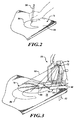
Fig. 2 is a perspective view of an exemplary workpiece having markings drawn on it by a writing instrument; -
Fig. 3 is a partial side perspective view of the power hand tool ofFig. 1 and shown cutting through the workpiece ofFig. 2 along the marking lines while the UV light illuminates the markings; -
Fig. 4 is an exemplary schematic view of a power tool constructed in accordance to additional features of the present teachings; -
Fig. 5 is an exemplary schematic view of a power tool constructed in accordance to the present teachings and cooperating with a portable UV light source; -
Fig. 6 is an exemplary schematic view of a machine constructed in accordance to various examples of the present teachings; -
Fig. 7 is a front perspective view of an exemplary sewing machine having a light source according to one example of the present teachings; -
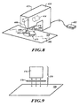
Fig. 8 is a partial side perspective view of the machine ofFig. 7 and shown performing a sewing stitch through an exemplary workpiece along the marking lines while the light source illuminates the markings; and -
Fig. 9 is a side perspective view of a light source according to additional features of the present teachings and including a light emitting member and a film. - Corresponding reference numerals indicate corresponding parts throughout the several views of the drawings.
- The following description is merely exemplary in nature and is not intended to limit the present teachings, their application or uses. It should be understood that throughout the drawings, corresponding reference numerals can indicate like or corresponding parts and features.
- Moreover, certain terminology can be used for the purpose of reference only and do not limit the present teachings. For example, terms such as "upper," "lower," "above" and "below" can refer to directions in the drawings to which reference is made. Terms such as "front," "back," "rear" and "side" can describe the orientation of portions of the component, function, system, etc. within a consistent but arbitrary frame of reference which can be made more clear by reference to the text and the associated drawings describing the component, function, system, etc. under discussion. Such terminology may include the words specifically mentioned above, derivatives thereof and words of similar import. Similarly, the terms "first," "second" and other such numerical terms referring to structures, systems and/or methods do not imply a sequence or order unless clearly indicated by the context.
- With initial reference to
Fig. 1 , a power tool constructed in accordance with the present teachings is shown and generally identified atreference numeral 10. Thepower tool 10 can generally comprise a housing 12 containing amotor 14. The housing 12 can generally comprise amain body 16, afront portion 18, arear portion 20, anupper portion 22 and alower portion 24. In one example, theupper portion 22 can define ahandle 30 having atrigger assembly 32. Apower switch 34 can be provided on theupper portion 22 of thetool 10. - When activated by the
trigger assembly 32, themotor 14 can provide a reciprocating and/or pendulum motion to an output member, such as acutting blade holder 40, on an end of a reciprocating shaft to drive acutting blade 42. Acontrol member 44 can be provided on themain body 16 of the housing 12. In one example, thecontrol member 44 can control a rate of reciprocation and/or a magnitude of a pendulum motion of thecutting blade 42. - While the
handheld power tool 10 is represented in the figures as a jigsaw, the teachings of the present disclosure are also applicable to other handheld power tools, such as, but not limited to, circulating saws, reciprocating saws, scroll saws, miter saw, band saws, portable band saws, rotary tools, cut-out tools, drills, routers, grinders, or any other tool in which an illumination of an area or path would assist the user in seeing a cutting or working line. As will be discussed in greater detail, the present teachings are applicable to machines in general or any device where following a path is recommended during use. - A
shoe member 50 can be coupled to thelower portion 24 of the housing 12. During use, abottom surface 54 of theshoe member 50 can abut aworkpiece 56, which can be wood, plastic, metal, other suitable materials and one or more combinations thereof and can be in the form of pipe, sheet material, stock material, other suitable forms and/or materials and one or more combinations thereof. Thehandheld power tool 10 can further comprise arolling blade guide 60 that can guide theblade 42 during reciprocating motion. Adust blower 62 can be disposed in the housing 12, such as near thelower portion 24. Thedust blower 62 can be configured to blow air onto theworkpiece 56 in a direction generally proximate to the cutting area of theblade 42 to disperse debris from theworkpiece 56 at an area adjacent to theblade 42. - The
handheld power tool 10 can further comprise alight source 70 having alight outlet 72. In one example, thelight source 70 can be disposed generally on thefront portion 18 of the housing 12. Thelight source 70 according to the present teachings can comprise an ultraviolet (UV) light. The UV light can be in the form of a bulb, a light-emitting diode (LED), or other forms. In one example, theUV light source 70 can include a black light. Thelight source 70 can be configured to shine light out of thelight outlet 72 and onto awork area 76 of theworkpiece 56. In one example, thelight source 70 can emit a generallywide beam 80 of UV light onto thework area 76 of theworkpiece 56. As will become appreciated from the following discussion, thelight source 70 can emit thebeam 80 onto thework area 76 of theworkpiece 56 to illuminate markings drawn by the user onto theworkpiece 56 that identify an area of interest such as a desired cut pattern for example. - With continual reference to
Fig. 1 and additional reference now toFigs. 2 and 3 , thehandheld power tool 10 and an exemplary method of using thehandheld power tool 10 will be described in greater detail. A writinginstrument 84 can be provided for drawingmarkings 86 onto theworkpiece 56. According to various examples, a writinginstrument 84 can comprise any writing tool that can mark a workpiece, such as a highlighter, a pencil, a pen, a marker, or other writing tool. According to various examples, the pencil can comprise a graphite pencil, a charcoal pencil, a crayon, a grease pencil, or other variety of pencil. The highlighter, according to various examples, can comprise any color, such as yellow for example. In this way, a user can draw themarkings 86 onto theworkpiece 56 to identify a desired line of cut. - As can be appreciated, in some examples, it may be desirable to cut along a curved cutting path (such as shown in
Fig. 2 ). According to one advantage of the present teachings, thelight source 70 can be adapted to transmit UV light onto the surroundingwork area 76 rather than simply project a line of light, such as provided by a laser, for example. By shining on an area, the UV light can shine on markings that are within thework area 76. - As shown in
Fig. 3 , thehandheld power tool 10 is shown cutting theworkpiece 56 along the marking 86. Thebeam 80 of thelight source 70 illuminates themarkings 86 by way of the UV light. In one example, the UV light can transmit radiation prompting visible effects of fluorescence and phosphorescence. More specifically, thebeam 80 of UV light illuminates themarkings 86 relative to the surroundingwork area 76 to make the markings easily visible by the user. As can be appreciated by those skilled in the art that while the UV light may be projected onto thework area 76 of theworkpiece 56, thework area 76 does not necessarily illuminate as would be the case with a conventional incandescent (or other) light bulb. Instead, the UV light will cause themarkings 86 to illuminate significantly relative to the remainder of the work area 76 (i.e., areas without themarkings 86 but within the work area 76). Also, as can be appreciated, thebeam 80 of UV light can effectively illuminate a curved path of themarkings 86, such that a user can effectively anticipate movements of thetool 10 as the user cuts through theworkpiece 56. - With reference now to
Fig. 4 , ahandheld power tool 110 according to additional features is shown. Thepower tool 110 can generally define atool housing 112. While not specifically shown inFig. 4 , thepower tool 110 can generally take the form of thehandheld power tool 10 described above with respect toFig. 1 . It is appreciated that while specific components shown in thepower tool 10 ofFig. 1 have been omitted in the illustration of thepower tool 110 ofFig. 4 that they are simply omitted for clarity purposes. - The
power tool 110 can comprise alight source 170 having alight outlet 172. Thelight source 170 having thelight outlet 172 can be generally provided as part of a light housing 174. Thelight source 170 can be configured to emit UV light as described above with respect to thelight source 170. Thepower tool 110 can further comprise a power distributor/converter that can convert alternating current (AC) from apower cord 178 into usable power for thepower tool 110. According to the example shown inFig. 4 , thepower tool 110 can include an on/offswitch 180. The on/offswitch 180 can be turned to an "on" position to communicate electrical power from the power distributor/converter 176 to thelight source 170. In one example, thelight source 170 can be powered by the same source as other components (i.e., the motor) of thepower tool 110. As can be appreciated, by turning the on/offswitch 180 to an "off" position, a user can disable power communication to thelight source 170 when thelight source 170 is not needed. It is appreciated that while thepower tool 110 has been shown with a standardAC power cord 178, thepower tool 110 can alternatively be powered by an onboard power source, such as batteries, for example. - Turning now to
Fig. 5 , a handheld power tool 210 will be described in cooperation with a portablelight source 270. Again, it is appreciated that the power tool 210 can be configured similar to thepower tool 10 illustrated inFig. 1 . In this way, features shown and described above with respect to the power tool 10 (ormachines 310, 410) can likewise be included on the power tool 210 ofFig. 5 . According to the example shown inFig. 5 , the power tool 210 can include a receivingmember 220 that can selectively couple with anattachment member 224 defined on a light housing 274 of thelight source 270. Thelight source 270 can be configured to transmit UV light, such as described above in relation to thepower tools light source 270 according to the example ofFig. 5 can be a self-contained light source having an onboard power supply 276 (such as batteries for example) electrically coupled to an on/offswitch 280 provided on the light housing 274. Thelight source 270 can define alight outlet 272 for emitting UV light onto a workpiece. - The receiving
member 220 andattachment member 224 can take various forms. In one example, the receivingmember 220 and theattachment member 224 can comprise a combination of fasteners that are configured to selectively mate with complementary features for securing thelight source 270 to the tool 210. It is appreciated that the receivingmember 220 and theattachment member 224 can take on other forms, such as, but not limited to, magnets. It is contemplated that the receivingmember 220 can be arranged such that when theattachment member 224 is coupled with the receivingmember 220, thelight outlet 272 is aligned for emitting the UV light onto the work area (i.e.,work area 76,Fig. 1 ). According to other features, it is contemplated that thelight outlet 272 can be adjustable, such that a user can alter the direction of emitted light from thelight outlet 272. It is also contemplated that the light source 70 (Fig. 1 ) and the light source 170 (Fig. 4 ) can also include an adjustablelight outlet work area 76 of theworkpiece 56. - Turning now to
Fig. 6 , a machine constructed in accordance with additional features of the present teachings is shown and generally identified atreference numeral 310. Themachine 310 can generally comprise a machine housing 312 containing adrive mechanism 314. Aninput member 332 can be coupled to the housing 312. Anoutput member 340 can be driven by thedrive mechanism 314 in response to an input from theinput member 332 and provide a resultant motion onto a working member 342. Themachine 310 can further comprise alight source 370 operable to shine a light out of thelight source 370 and onto awork area 376 of aworkpiece 356. Thelight source 370 can emit a generallywide beam 380 of UV light onto thework area 376 of theworkpiece 356. By way of example, themachine 310 can comprise any machine used to perform a task on a workpiece. More particularly, themachine 310 can comprise any machine used to manipulate (i.e., cut, drill, grind, join, sew, weld, etc.) a workpiece 356 (including multiple workpieces concurrently) where an operator may follow a path identified on the workpiece 356 (markings, etc) with the working member 342. In this way, the working member can include, for example, a blade, a bit, a grinding wheel, a needle, other cutting instruments or joining instruments, and others. Thedrive mechanism 314 can comprise a motor such as described above with respect to themotor 14. Thedrive mechanism 314 can also comprise non-motorized devices such as hand operated devices or other apparatus that can impart motion onto anoutput member 340. - Turning now to
Fig. 7 , asewing machine 410 constructed in accordance to one example of the present teachings is shown. Thesewing machine 410 can generally comprise asewing machine housing 412 having a drive mechanism 414 in the form of a motor. Aninput member 432 can be coupled to thesewing machine 410 for providing a signal to the drive mechanism 414. Theinput member 432 according to one example can comprise a foot pedal. The drive mechanism 414 can drive anoutput member 440 such as a needle holder. Theoutput member 440 can selectively retain a working member such as aneedle 442. As can be appreciated, theneedle 442 can be adapted to carry a flexible member such as athread 446. As can be appreciated, repeatedly passing theneedle 442 through aworkpiece 456 can secure theflexible member 446 to theworkpiece 456 along a path. Alight source 470 can project light onto theworkpiece 456. Thelight source 470 can emit a generallywide beam 480 of UV light onto awork area 476 of theworkpiece 456. Theexemplary workpiece 456 ofFig. 7 can be any material suitable for sewing such as, but not limited to fabric, textiles or leather for example. Thesewing machine 410 can further comprise a power distributor/converter that can convert alternating current (AC) from a power cord into usable power as described above in relation to thepower tool 110 inFig. 4 . - With continued reference to
Fig. 7 and additional reference now toFig. 8 , themachine 410 and an exemplary method of using themachine 410 will be described in greater detail. A writing instrument (such as the writinginstrument 84 described above and shown inFig. 2 ) can be used for drawingmarkings 486 onto theworkpiece 456. In one example, a user can draw themarkings 486 onto theworkpiece 456 to identify a desired sewing line. Those skilled in the art will appreciate that thesewing line 486 may be identified along a single workpiece (a single piece of material such as fabric) or can alternatively represent a line indicating where multiple pieces of material will be joined by thethread 446 during a sewing operation. As with the examples described above, thelight source 470 can be adapted to transmit UV light onto the surroundingwork area 476 rather than simply project a line of light, such as provided by a laser, for example. By shining light onto an area, the UV light can shine on markings that are within thework area 476. As shown inFig. 8 , themachine 410 is shown sewing along the marking 486 of theworkpiece 456. Thebeam 480 of thelight source 470 illuminates themarkings 486 by way of the UV light. As described above, the UV light can transmit radiation prompting visible effects of fluorescence and phosphorescence. Also as described above, the UV light will cause themarkings 486 to illuminate significantly relative to the remainder of the work area 476 (i.e., areas without themarkings 486, but within the work area 476). - Turning now to
Fig. 9 , a light source 570 according to additional features of the present teachings is shown. The light source 570 can be collectively defined by alight emitting device 574 and afilter 578. Thelight emitting device 574 can include any light source, such as an incandescent bulb, a light emitting diode, a fluorescent bulb or others that is capable of emitting at least partially a percentage of UV light. Explained differently, the light source 570 can be configured to emit a percentage of black light and a remaining percentage of other light. Thefilter 578 can be a black light filter or other filter that is operable to filter out visible light (i.e., other light identified above) and only allow black light to pass through. Thelight source 470 can be substituted for any of thelight sources - While specific aspects have been described in the specification and illustrated in the drawings, it will be understood by those skilled in the art that various changes can be made and equivalents can be substituted for elements and components thereof without departing from the scope of the present teachings, as defined in the claims. Furthermore, the mixing and matching of features, elements, components and/or functions between various aspects of the present teachings are expressly contemplated herein so that one skilled in the art will appreciate from the present teachings that features, elements, components and/or functions of one aspect of the present teachings can be incorporated into another aspect, as appropriate, unless described otherwise above. Moreover, many modifications may be made to adapt a particular situation, configuration or material to the present teachings without departing from the essential scope thereof. Therefore, it is intended that the present teachings not be limited to the particular aspects illustrated by the drawings and described in the specification as the best mode presently contemplated for carrying out the present teachings, but that the scope of the present teachings include many aspects and examples following within the foregoing description and the appended claims.
- The foregoing description of the embodiments has been provided for purposes of illustration and description. It is not intended to be exhaustive or to limit the invention. Individual elements or features of a particular embodiment are generally not limited to that particular embodiment, but, where applicable, are interchangeable and can be used in a selected embodiment, even if not specifically shown or described. The same may also be varied in many ways. Such variations are not to be regarded as a departure from the invention, and all such modifications are intended to be included within the scope of the invention.
Claims (15)
- A machine (10, 110, 210, 310, 410) characterized in that it includes:a machine housing (12, 112, 312, 412);a drive mechanism (14, 314, 414) disposed in the machine housing and driving an output member (40, 340, 440);an input member (32, 332, 432) associated with the machine housing for activating the drive mechanism;a working member (42, 342, 442) driven by the output member; anda light source (70, 170, 270, 370, 470, 570) coupled to the machine housing that projects UV light onto an area proximate to the working member.
- The machine of claim 1 wherein the light source comprises a UV light source.
- The machine of claim 1 wherein the light source collectively defines a light emitting device (574) and a filter (578), wherein the filter allows black light to pass therethrough.
- The machine of claim 3 wherein the light emitting device comprises one of an incandescent bulb, a light emitting diode and a fluorescent bulb.
- The machine of claim 1, further comprising a writing instrument (84) operable to place markings onto a workpiece (56, 356, 456), the markings corresponding to a working pattern and wherein the UV light illuminates the working pattern relative to the area proximate to the working member.
- The machine of claim 1 wherein the light source is disposed on the machine housing generally proximate to the working member.
- The machine of claim 6 wherein the light source is powered by a power source (276) internal to the machine housing.
- The machine of claim 7 wherein the light source is powered by a common power source (178) as the drive mechanism.
- The machine of claim 8, further comprising a switch (180) to selectively electrically connect the light source to the common power source.
- The machine of claim 6 wherein the light source is disposed in a light housing (274) that is portable and comprises an internal power source.
- The machine of claim 1 wherein the machine comprises a sewing machine (410).
- The machine of claim 11 wherein the working member comprises a needle (442).
- The machine of claim 12 wherein the input member comprises a foot pedal (432).
- A method of manipulating a workpiece (56, 356, 456) with a machine (10, 110, 210, 310, 410), the method comprising:marking a pattern onto the workpiece with a writing instrument (84);activating a UV light source (70, 170, 270, 370, 470, 570) associated with the workpiece, the UV light source emitting light that makes the markings of the pattern appear optically brighter relative to the surrounding areas of the workpiece in range of the emitted light; andmanipulating the workpiece with a working member (42, 342, 442) on the machine while directing the working member substantially along the markings.
- The method of claim 14 wherein the working member includes a needle (442) and manipulating the workpiece includes repeatedly passing the needle through the workpiece to secure a flexible member (446) carried by the needle substantially along the markings.
Applications Claiming Priority (2)
| Application Number | Priority Date | Filing Date | Title |
|---|---|---|---|
| US12/166,089 US20100000094A1 (en) | 2008-07-01 | 2008-07-01 | Power tool with uv illumination |
| US12/277,953 US20100002415A1 (en) | 2008-07-01 | 2008-11-25 | Machine with uv illumination |
Publications (1)
| Publication Number | Publication Date |
|---|---|
| EP2140961A1 true EP2140961A1 (en) | 2010-01-06 |
Family
ID=41128068
Family Applications (1)
| Application Number | Title | Priority Date | Filing Date |
|---|---|---|---|
| EP09162848A Withdrawn EP2140961A1 (en) | 2008-07-01 | 2009-06-16 | Machine with UV Illumination |
Country Status (3)
| Country | Link |
|---|---|
| US (1) | US20100002415A1 (en) |
| EP (1) | EP2140961A1 (en) |
| CN (1) | CN201470940U (en) |
Families Citing this family (12)
| Publication number | Priority date | Publication date | Assignee | Title |
|---|---|---|---|---|
| US8602578B2 (en) * | 2008-12-17 | 2013-12-10 | Patricia Lynn Risinger | Tabletop light for machine sewing |
| US8317350B2 (en) | 2009-02-25 | 2012-11-27 | Black & Decker Inc. | Power tool with a light for illuminating a workpiece |
| US8328381B2 (en) | 2009-02-25 | 2012-12-11 | Black & Decker Inc. | Light for a power tool and method of illuminating a workpiece |
| US20110058356A1 (en) | 2009-02-25 | 2011-03-10 | Black & Decker Inc. | Power tool with light emitting assembly |
| US9328915B2 (en) | 2010-09-30 | 2016-05-03 | Black & Decker Inc. | Lighted power tool |
| US9028088B2 (en) | 2010-09-30 | 2015-05-12 | Black & Decker Inc. | Lighted power tool |
| US12059780B2 (en) | 2010-09-30 | 2024-08-13 | Black & Decker Inc. | Lighted power tool |
| AU2012202705B8 (en) * | 2011-03-07 | 2014-11-06 | Infusion Brands, Inc. | Dual blade reciprocating saw |
| WO2012121943A2 (en) * | 2011-03-08 | 2012-09-13 | Infusion Brands, Inc. | Dual bladed jig saw |
| RU2013151797A (en) * | 2011-04-21 | 2015-05-27 | Инфьюжн Брэндс, Инк. | MULTI-FUNCTIONAL SAW OF BIDIRECTIONAL VIBRATION ACTION |
| US9242355B2 (en) | 2012-04-17 | 2016-01-26 | Black & Decker Inc. | Illuminated power tool |
| US20140340871A1 (en) * | 2013-05-16 | 2014-11-20 | Judy Cash | Sewing Machine Uplight Assembly |
Citations (5)
| Publication number | Priority date | Publication date | Assignee | Title |
|---|---|---|---|---|
| US3862409A (en) * | 1973-10-11 | 1975-01-21 | Thomas Joella | Lighted table for the use with sewing machines |
| EP0971061A1 (en) * | 1997-03-24 | 2000-01-12 | Hashimoto, Yoshiko | Sewing system and sewing method |
| JP2005066754A (en) * | 2003-08-25 | 2005-03-17 | Ryobi Ltd | Power tool |
| WO2007149131A2 (en) * | 2006-06-20 | 2007-12-27 | Padana Ag | Automatic clipping line |
| US12166089B2 (en) | 2020-07-30 | 2024-12-10 | Taiwan Semiconductor Manufacturing Company Ltd. | Method of manufacturing semiconductor device and associated memory device |
Family Cites Families (19)
| Publication number | Priority date | Publication date | Assignee | Title |
|---|---|---|---|---|
| US3839637A (en) * | 1972-03-22 | 1974-10-01 | A Willis | Textile guiding and measuring indicia |
| US4596172A (en) * | 1983-04-29 | 1986-06-24 | Oliver Machinery Company | Lumber cutting saw |
| US4833782A (en) * | 1987-06-01 | 1989-05-30 | Robert E. Strauss | Saber saw tracing light |
| US5038481A (en) * | 1990-05-04 | 1991-08-13 | Lonnie Smith | Saber saw tracking light |
| US5285708A (en) * | 1992-05-18 | 1994-02-15 | Porter-Cable Corporation | Miter saw alignment system |
| US5446635A (en) * | 1993-06-24 | 1995-08-29 | Quarton, Inc. | Laser assembly for marking a line on a workpiece for guiding a cutting tool |
| US5675899A (en) * | 1996-05-28 | 1997-10-14 | Webb; James | Rotary saw with laser beam alignment |
| DE19631306C2 (en) * | 1996-08-02 | 2001-06-28 | Wolfgang Madlener | Laser light barrier system for tool and workpiece measurement |
| DE69822637T2 (en) * | 1997-07-10 | 2005-02-03 | Avos Developments Ltd., Kelston | LIGHTING DEVICE FOR POWER-OPERATED TOOLS |
| IT1313279B1 (en) * | 1999-07-30 | 2002-07-17 | Makita S P A | LIGHTING DEVICE FOR ELECTRIC MACHINE TOOLS AND MACHINE TOOL INCLUDING SUCH DEVICE. |
| US6692200B2 (en) * | 2001-01-16 | 2004-02-17 | Nesson Enterprises | Alignment system for hand-held tools |
| JP2002337101A (en) * | 2001-05-15 | 2002-11-27 | Makita Corp | Jigsaw |
| US6565227B1 (en) * | 2001-11-13 | 2003-05-20 | Greg Davis | Method and device for tool alignment |
| US6937336B2 (en) * | 2002-08-15 | 2005-08-30 | Black & Decker, Inc. | Optical alignment system for power tool |
| CN2576386Y (en) * | 2002-11-19 | 2003-10-01 | 南京泉峰国际贸易有限公司 | Secondary handle with laser positioning measuring-scale used on drilling tools |
| US7101058B2 (en) * | 2003-10-07 | 2006-09-05 | Robert Bosch Gmbh | Light assembly |
| US7140118B2 (en) * | 2004-09-13 | 2006-11-28 | Merle Skip Adrian | Workpiece center and edge finder having visual light indicator |
| DE102005021383A1 (en) * | 2005-05-04 | 2006-11-09 | Robert Bosch Gmbh | Rechargeable battery-electric hand tool machine, has LED diode utilized as light source, which switches on light system, where light of diode is erected on operating field, and diode and light control system are arranged in light pipe |
| US7331113B1 (en) * | 2007-04-19 | 2008-02-19 | Algird Patrick | Tool alignment device |
-
2008
- 2008-11-25 US US12/277,953 patent/US20100002415A1/en not_active Abandoned
-
2009
- 2009-06-16 EP EP09162848A patent/EP2140961A1/en not_active Withdrawn
- 2009-07-01 CN CN2009201565418U patent/CN201470940U/en not_active Expired - Fee Related
Patent Citations (5)
| Publication number | Priority date | Publication date | Assignee | Title |
|---|---|---|---|---|
| US3862409A (en) * | 1973-10-11 | 1975-01-21 | Thomas Joella | Lighted table for the use with sewing machines |
| EP0971061A1 (en) * | 1997-03-24 | 2000-01-12 | Hashimoto, Yoshiko | Sewing system and sewing method |
| JP2005066754A (en) * | 2003-08-25 | 2005-03-17 | Ryobi Ltd | Power tool |
| WO2007149131A2 (en) * | 2006-06-20 | 2007-12-27 | Padana Ag | Automatic clipping line |
| US12166089B2 (en) | 2020-07-30 | 2024-12-10 | Taiwan Semiconductor Manufacturing Company Ltd. | Method of manufacturing semiconductor device and associated memory device |
Also Published As
| Publication number | Publication date |
|---|---|
| US20100002415A1 (en) | 2010-01-07 |
| CN201470940U (en) | 2010-05-19 |
Similar Documents
| Publication | Publication Date | Title |
|---|---|---|
| US20100002415A1 (en) | Machine with uv illumination | |
| US20100000094A1 (en) | Power tool with uv illumination | |
| JP6715248B2 (en) | Optical display unit for use in a hand-held machine tool, and hand-held machine tool | |
| AU740537B2 (en) | Illumination for power tools | |
| US10174934B2 (en) | Rotary power tool lighting system | |
| US1898956A (en) | Saw attachment for electric drills | |
| US20080229589A1 (en) | Power tool having improved visibility of the cutting area | |
| EP3984675B1 (en) | Compact multi-material cut-off tool | |
| WO2009076875A1 (en) | A table tool | |
| JP5452276B2 (en) | Power tool lighting device | |
| CN102431015A (en) | Hand-held power tool e.g. rechargeable battery-drilling hammer, for drilling work piece and/or wall, has work area grip and handle connected with each other, and lighting unit and charge state display arranged in base area of housing | |
| GB2420087A (en) | Hand machine tool | |
| AU2020274440B2 (en) | Portable machine tool | |
| AU2009200187A1 (en) | Laser line generator and power tool | |
| CN212652811U (en) | Reciprocating saw | |
| CN114074199B (en) | Reciprocating saw | |
| CN1915594A (en) | Hand-held grinding tool | |
| CN119604377A (en) | Removable light module | |
| US11772224B2 (en) | Compact multi-material cut-off tool | |
| JP4923883B2 (en) | Electric tool | |
| JP2005066754A (en) | Power tool | |
| CN101716694A (en) | Machine tool, in particular hand-held machine tool | |
| AU2004100043A4 (en) | Laser line generator and power tool | |
| JP2004284013A (en) | Electric cutting machine | |
| JP7495793B2 (en) | Work Machine |
Legal Events
| Date | Code | Title | Description |
|---|---|---|---|
| PUAI | Public reference made under article 153(3) epc to a published international application that has entered the european phase |
Free format text: ORIGINAL CODE: 0009012 |
|
| AK | Designated contracting states |
Kind code of ref document: A1 Designated state(s): AT BE BG CH CY CZ DE DK EE ES FI FR GB GR HR HU IE IS IT LI LT LU LV MC MK MT NL NO PL PT RO SE SI SK TR |
|
| 17P | Request for examination filed |
Effective date: 20100120 |
|
| 17Q | First examination report despatched |
Effective date: 20100303 |
|
| STAA | Information on the status of an ep patent application or granted ep patent |
Free format text: STATUS: THE APPLICATION IS DEEMED TO BE WITHDRAWN |
|
| 18D | Application deemed to be withdrawn |
Effective date: 20100914 |