EP2140907A1 - Port assembly for use with needleless connector - Google Patents
Port assembly for use with needleless connector Download PDFInfo
- Publication number
- EP2140907A1 EP2140907A1 EP09251635A EP09251635A EP2140907A1 EP 2140907 A1 EP2140907 A1 EP 2140907A1 EP 09251635 A EP09251635 A EP 09251635A EP 09251635 A EP09251635 A EP 09251635A EP 2140907 A1 EP2140907 A1 EP 2140907A1
- Authority
- EP
- European Patent Office
- Prior art keywords
- base
- pivot
- port assembly
- disposed
- port
- Prior art date
- Legal status (The legal status is an assumption and is not a legal conclusion. Google has not performed a legal analysis and makes no representation as to the accuracy of the status listed.)
- Withdrawn
Links
- 239000012530 fluid Substances 0.000 claims abstract description 40
- 239000012528 membrane Substances 0.000 claims abstract description 23
- 238000004891 communication Methods 0.000 claims abstract description 8
- 238000007789 sealing Methods 0.000 claims description 5
- 229940079593 drug Drugs 0.000 description 10
- 239000003814 drug Substances 0.000 description 10
- 239000000243 solution Substances 0.000 description 8
- 230000000712 assembly Effects 0.000 description 5
- 238000000429 assembly Methods 0.000 description 5
- 230000004888 barrier function Effects 0.000 description 5
- 239000000463 material Substances 0.000 description 4
- 230000007246 mechanism Effects 0.000 description 3
- 208000036647 Medication errors Diseases 0.000 description 2
- 238000005516 engineering process Methods 0.000 description 2
- 230000001012 protector Effects 0.000 description 2
- 239000007787 solid Substances 0.000 description 2
- 239000000126 substance Substances 0.000 description 2
- 229920001169 thermoplastic Polymers 0.000 description 2
- 239000004416 thermosoftening plastic Substances 0.000 description 2
- 210000003462 vein Anatomy 0.000 description 2
- 230000000295 complement effect Effects 0.000 description 1
- 238000011109 contamination Methods 0.000 description 1
- 235000015872 dietary supplement Nutrition 0.000 description 1
- 239000011888 foil Substances 0.000 description 1
- 230000006870 function Effects 0.000 description 1
- 239000011521 glass Substances 0.000 description 1
- 230000036512 infertility Effects 0.000 description 1
- 238000002347 injection Methods 0.000 description 1
- 239000007924 injection Substances 0.000 description 1
- 238000001990 intravenous administration Methods 0.000 description 1
- 230000013011 mating Effects 0.000 description 1
- 230000008520 organization Effects 0.000 description 1
- 229920000642 polymer Polymers 0.000 description 1
- 238000000926 separation method Methods 0.000 description 1
- 238000012421 spiking Methods 0.000 description 1
- 238000002560 therapeutic procedure Methods 0.000 description 1
- 239000010409 thin film Substances 0.000 description 1
- 238000012800 visualization Methods 0.000 description 1
- 229940088594 vitamin Drugs 0.000 description 1
- 229930003231 vitamin Natural products 0.000 description 1
- 235000013343 vitamin Nutrition 0.000 description 1
- 239000011782 vitamin Substances 0.000 description 1
- 239000002699 waste material Substances 0.000 description 1
- 238000003466 welding Methods 0.000 description 1
Images



Classifications
-
- A—HUMAN NECESSITIES
- A61—MEDICAL OR VETERINARY SCIENCE; HYGIENE
- A61M—DEVICES FOR INTRODUCING MEDIA INTO, OR ONTO, THE BODY; DEVICES FOR TRANSDUCING BODY MEDIA OR FOR TAKING MEDIA FROM THE BODY; DEVICES FOR PRODUCING OR ENDING SLEEP OR STUPOR
- A61M39/00—Tubes, tube connectors, tube couplings, valves, access sites or the like, specially adapted for medical use
- A61M39/22—Valves or arrangement of valves
- A61M39/221—Frangible or pierceable closures within tubing
-
- A—HUMAN NECESSITIES
- A61—MEDICAL OR VETERINARY SCIENCE; HYGIENE
- A61M—DEVICES FOR INTRODUCING MEDIA INTO, OR ONTO, THE BODY; DEVICES FOR TRANSDUCING BODY MEDIA OR FOR TAKING MEDIA FROM THE BODY; DEVICES FOR PRODUCING OR ENDING SLEEP OR STUPOR
- A61M39/00—Tubes, tube connectors, tube couplings, valves, access sites or the like, specially adapted for medical use
- A61M39/22—Valves or arrangement of valves
- A61M39/26—Valves closing automatically on disconnecting the line and opening on reconnection thereof
-
- Y—GENERAL TAGGING OF NEW TECHNOLOGICAL DEVELOPMENTS; GENERAL TAGGING OF CROSS-SECTIONAL TECHNOLOGIES SPANNING OVER SEVERAL SECTIONS OF THE IPC; TECHNICAL SUBJECTS COVERED BY FORMER USPC CROSS-REFERENCE ART COLLECTIONS [XRACs] AND DIGESTS
- Y10—TECHNICAL SUBJECTS COVERED BY FORMER USPC
- Y10S—TECHNICAL SUBJECTS COVERED BY FORMER USPC CROSS-REFERENCE ART COLLECTIONS [XRACs] AND DIGESTS
- Y10S604/00—Surgery
- Y10S604/905—Aseptic connectors or couplings, e.g. frangible, piercable
Definitions
- This patent is directed to a port assembly for use with a needleless connector, and, in particular, to a port assembly for use with a needleless connector wherein the port assembly includes a pivoting cutting mechanism.
- Intravenous (“I.V.”) therapy involves the delivery of fluids to a patient through a vein.
- a catheter is placed into the vein of the patient, and then fluids are administered to the patient through the catheter.
- the catheter is connected to an administration set in communication with a container, such as a flexible container or bag, from which fluids are infused into the patient.
- the flexible container conventionally has two ports, an administration port (“admin port”) and a medication port (“med port”), each port serving a different purpose.
- the admin port is used to access the solution in the container to infuse fluid from the container into the patient.
- the med port is used by a healthcare worker or a pharmacist to access the solution in the container to aspirate solution or to introduce medication and/or other substances (e.g.., nutritional supplements, vitamins, etc.) into the container.
- the admin port is usually defined a thermoplastic tube or chimney with a solid thermoplastic membrane is disposed in the tube or chimney, the membrane preventing access to the solution in the container.
- a sharp spike (such as may conform to International Organization for Standardization Standard ISO 8536-4) is inserted into the tube or chimney, and advanced along the tube or chimney to pierce the membrane. The spike is attached to the administration set, and thereby establishes fluid communication between the container and the set.
- the med port conventionally usually includes a solid rubber septum that may be pierced using a needle, pointed cannula or other sharp instrument, such as a "reconstitution adapter".
- the sharp, pointed instruments used to access the solution in the container via the admin or med ports represent an accidental puncture hazard to the healthcare worker or the pharmacist using the instrument, as well as a hazard to the patient, the equipment (e.g., the container), and others involved in the patient's healthcare.
- the traditional unshrouded sharp spikes used to access the admin port can cause damage to container upon spiking.
- the spikes also present a puncture hazard to healthcare workers who handle the container as a waste container, especially where the container is a thin-film bag.
- a fluid container includes a receptacle for retaining a fluid, and at least one conduit in communication with the receptacle.
- the at least one conduit is defined, at least in part, by a port assembly.
- the port assembly includes a valve housing with an inlet opening, a valve disposed in the valve housing to control access through the inlet opening, and a base having an outlet opening that is initially occluded by a membrane.
- a pivot is disposed within the base and has a cutting surface disposed within the base, the cutting surface rupturing the membrane at least in part as the pivot is pivoted about an axis between first and second positions.
- a port assembly to be used in a conduit of a fluid container includes a valve housing with an inlet opening, a valve disposed in the valve housing to control access through the inlet opening, and a base having an outlet opening that is initially occluded by a membrane.
- a pivot is disposed within the base and has a cutting surface disposed within the base, the cutting surface rupturing the membrane at least in part as the pivot is pivoted about an axis between first and second positions.
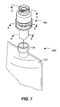
- Fig. 1 is a fragmentary, perspective view of an embodiment of a fluid container with a needleless connector assembly
- Fig. 2 is an exploded, perspective view of a needleless connector assembly as shown in Fig. 1 ;
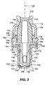
- Fig. 3 is an enlarged, cross-sectional view of the needleless connector assembly of Fig. 1 taken about line 3-3;
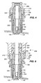
- Fig. 4 is an enlarged, cross-sectional view of the needleless connector assembly of Fig. 1 in a standby state;
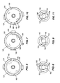
- Fig. 5 is an enlarged, cross-sectional view of the needleless connector assembly of Fig. 1 taken about line 5-5 prior to barrier rupture;
- Fig. 6 is an enlarged, cross-sectional view of the needleless connector assembly of Fig. 1 taken about line 6-6 prior to barrier rupture;
- Fig. 7 is an enlarged, cross-sectional view of the needleless connector assembly of Fig. 1 taken about line 5-5 prior to during rupture;
- Fig. 8 is an enlarged, cross-sectional view of the needleless connector assembly of Fig. 1 taken about line 6-6 prior to during rupture;
- Fig. 9 is a combination of the male needleless connector and the needleless connector assembly in an inserted state, after rupture of the barrier;
- Fig. 10 is an enlarged, cross-sectional view of the needleless connector assembly of Fig. 1 taken about line 5-5 after to barrier rupture;
- Fig. 11 is an enlarged, cross-sectional view of the needleless connector assembly of Fig. 1 taken about line 6-6 after to barrier rupture;
- Fig. 12 is a perspective view of a two-port fluid container with a needleless connector assembly introduced into one port;
- Fig. 13 is a perspective view of a two-port fluid container with a needleless connector assembly introduced into both ports;
- Fig. 14 is a perspective view of a one-port fluid container with a needleless connector assembly introduced into the port;
- Fig. 15 is a perspective view of a two-port fluid container having a gondola with a needleless connector assembly introduced into one port;
- Fig. 16 is a perspective view of a two-port fluid container having a gondola with a needleless connector assembly introduced into both ports.
- Fig. 1 illustrates a fluid container 100 according to the present disclosure.
- the fluid container 100 includes a receptacle 102 for retaining a fluid, and at least one conduit 104 in communication with the receptacle 102.
- the receptacle 102 is a flexible bag formed using a polymer.
- the receptacle 102 could be a rigid-wall container, such as a glass bottle, or other container, such as a cartridge, unfilled flexible container, etc.
- the fluid container of Fig. 1 is illustrated in combination with a first embodiment of a needleless port assembly, or port assembly, 106.
- the needleless port assembly 106 is disposed in a port tube, as illustrated, to define the conduit 104.
- the port assembly 106 is shown separately from the port tube in the embodiment illustrated in Fig. 1 , the port assembly 106 may include one or more structures that are integral with the remainder of the conduit 104, as illustrated and explained below.
- the port assembly 106 includes a valve housing 108 with an inlet opening 110, and a valve 112 disposed in the valve housing 108 to control access through the inlet opening 110.
- the valve 112 may be, as illustrated, a luer activated valve. As seen in Fig. 3 , a first end 114 of the valve 112 abuts a seat 116 disposed at a first end 118 of the housing 108 about the inlet opening 110.
- the seat 116 may be defined by one or more shoulders that abut against one or more cooperating shoulders formed at the first end 114 of the valve 112. The valve 112 and the seat 116 fit together to form a seal to limit passage through the opening 110.
- the port assembly 106 also includes a base 120.
- certain structures of the port assembly 106 may be formed integrally (e.g., molded) with the structures that define the conduit 104 (e.g., the chimney of a gondola, as explained in greater detail below relative to Figs. 15-16 ); the base 120 is one such structure.
- the base 120 may have at least one outlet opening 122 that is initially occluded by a membrane 124; as illustrated in Fig. 3 , the base 120 includes two such outlet openings 122 that are initially occluded by a membrane 124. It will be recognized that the number of openings included in a particular embodiment of the port assembly 106 may vary.
- a pivot 126 is disposed, in part, within the base 120 and has a cutting surface 130 disposed within the base 120, the cutting surface 130 rupturing the membrane 124 at least in part as the pivot 126 is pivoted about an axis 128 between first and second positions (compare Figs. 4-6 with Figs. 9-11 ). As illustrated, the axis 128 is centered relative to the housing 108, the base 120, and the pivot 126, although this need not be the case according to all embodiments.
- the base 120 has a longitudinal bore 132 with a first open end 134 and a second closed end 136, the second closed end 136 defined in part by the membrane 124.
- the pivot 126 has an elongated shaft 138, the elongate shaft 138 being disposed in the longitudinal bore 132 with the cutting surface 130 disposed adjacent the second end 136 of the bore 132.
- the cutting surface 130 may be defined on one or more arms 140 that depend radially outwardly from an end 142 of the shaft 138. As illustrated, each arm 140 includes an angled edge that defines in part the cutting surface 130. The operation of the cutting surface 130 will be explained in greater detail below with reference to Figs. 4-11 .
- a sealing member 144 may be disposed about the elongated shaft 138, with the sealing member 144 being disposed between the longitudinal bore 132 and the elongated shaft 138 with the elongated shaft 138 disposed within the longitudinal bore 132.
- the shaft 138 may have a groove 146 formed in an outer surface 148 of the shaft 138 between the first end 142 of the shaft 138 and a second end 150.
- the sealing member 144 which may be an O-ring, for example, is seated within the groove 146, and is compressed between the bore 132 and shaft 138 to limit the passage of materials past the seal thus formed.
- the valve housing 108 is attached to the pivot 126 with the valve 112 disposed therebetween.
- the pivot 126 may have an annular ring 152 that defines a shoulder 154 with a surface 156 of a flange 158.
- a rim 160 of the valve housing 108 fits about the ring 152 with an end 162 of the valve housing 108 abutting the shoulder 154.
- the rim 160 of the valve housing 108 may be attached to the ring 152 of the pivot 126 through ultrasonic welding.
- the pivot 126 is also attached to the base 120, but such that the pivot 126 is free to move about its axis 128 relative to the base 120.
- the base 120 has a flange 164 and the pivot 126 includes at least one lug or hook 166 that cooperates with the base flange 164 to attach the pivot 126 to the base 120; as illustrated, the pivot 126 includes two hooks 166.
- the hooks 166 may depend from the flange 158 of the pivot 126 from a surface 168 opposite the surface 156.
- Each hook 166 has an edge 170 that cooperates with a surface 172 of the base flange 164 to limit the separation of the pivot 126 from the base 120.
- the pivot 126 is pivoted about an axis 128 between first and second positions.
- the base 120 and pivot have structures that cooperate in at least the first and second positions.
- the base 120 has at least one tab or rib 180, 182 and the pivot 126 has at least one notch 184, 186 (which may itself be defined by opposing walls of adjacent tabs or ribs), which tabs 180, 182 and notches 184, 186 fit together to control the movement of the pivot 126 between the first and second positions.
- tabs 180, 182 and notches 184, 186 may be reversed, such that the tabs 180, 182 are disposed on the pivot 126 and the notches 184, 186 are formed by structures associated with the base 120.
- the base 120 has a first tab 180 and the pivot 126 has a first notch 184.
- the first tab 180 is received within the first notch 184 to hold the pivot 126 in a "standby" position until the operator is prepared to move the pivot 126 from the first position to the second position.
- the base 120 also has a second tab 182 and a pivot 126 has a second notch 186.
- the second tab 182 is received within the second notch 186 to lock the pivot 126 in the second position.
- a ramp 188 may also be provided leading up to the second notch 186.
- the base 120 and the pivot 126 may include mating structures that assist the motion of the pivot 126 about the axis 128.
- the base 120 may include a pin or projection 190
- the pivot may include a recess 192 complementary in shape to the center pin 190.
- the pin 190 has a hemispherical shape
- the recess 192 also has a hemispherical shape. The cooperation between the pin 190 and the recess 192 assists in the movement of the pivot 126 about the axis 128, as well as maintaining the pivot 126 aligned with the axis 128.
- pin 190 and the recess 192 may be used for the pin 190 and the recess 192, as well as the fact that the placement of the pin 190 and recess 192 may be reversed, such that the pin 190 depends from the pivot 126 and the recess 192 is formed in the base 120.
- the port assembly 106 is illustrated in Fig. 9 in combination with a male needleless connector 200, which cooperates with the port assembly 106.
- the connector 200 has a luer 202 that is surrounded by a threaded region 204, which is in turn surrounded by a shroud or skirt 206.
- the threaded region 204 of the connector 200 is intended to cooperate with threads 208 on an outer surface 210 of the housing 108; according to other embodiments, the threads 208 may extend to a further or a lesser extent about the housing 108.
- a connector such as a connector 200 may be referred to as a "luer lock.”
- the luer 202 has not yet come into contact with the first end 114 of the valve 112.
- the pivot 126 is at its extrememost first position, such that the tab 180 is received within the notch 184.
- the threaded region 204 is brought into contact with the threads 208 on the outer surface 210 of the housing 108, the luer 202 is advanced into the valve 112.
- the arms 140 located at the end 142 of the shaft 138 are also pivoting about the axis 128.
- the pivoting of the arms 140 brings the edges of the arms into contact with the membrane 124 disposed over the openings 122.
- the motion of the edges across the membrane 124 causes the membrane 124 to rupture, resulting in the opening of the outlet openings 122. Compare Figs. 6, 8 and 11 .
- valve 112 and the pivot 126 have internal passages 220, 222 through which fluid from the luer 202 of the male connector 200 may pass when the connector 200 is attached to the port assembly 106.
- the end 142 of the shaft 138 has openings or lumens 224 defined therein, through which fluid passing through the passages 220, 222 may pass. These openings 224 are in fluid communication with the openings 122 via the space between the bore 132 and the shaft 138.
- a needleless port assembly may be incorporated into a fluid container according to any of a variety of configurations.
- Figs. 12-14 illustrate embodiments wherein a fluid container includes a port tube, the port assembly disposed in the port tube to define the conduit.
- Figs. 15 and 16 illustrate embodiments wherein a fluid container includes a gondola, the gondola including a chimney that is formed integrally with the base of the port assembly to define the conduit.
- the port assemblies would have sterile port protectors or caps covering the ends; the caps have not been shown to facilitate visualization of the port assembly placement.
- the port assembly may have a peelable foil seal disposed over the inlet opening 110 as a sterility protector.
- Fig. 12 illustrates an embodiment wherein the port assembly is utilized in the medication port, and another mechanism, such as a conventional spike, is used in the administration port.
- Fig. 13 illustrates an embodiment wherein a port assembly according to the present disclosure is utilized in both the administration and the medication ports.
- Fig. 14 illustrates an embodiment wherein the port assembly is utilized in a single port embodiment.
- Fluid containers utilizing gondolas have a similar convention relative to the designation of medication and administration ports, the use of the gondola resulting from difficulties occurring in attaching the chimney material to the receptacle material.
- Fig. 15 like Fig. 12
- Fig. 16 like Fig. 13
- the base 120 may be formed integrally (i.e., as one piece) with the gondola, as discussed above.
- the use of the port assembly as described herein eliminates the use of sharp instruments, such as needles and reconstitution adapters, as have been used with conventional med ports, thereby eliminating the hazard posed to the pharmacist and the equipment (e.g., the container). Additionally, because the size of the luer used with luer-activated valves is significantly larger than the lumen size of needles used with the conventional med ports, there may be a reduced force required to aspirate solution or to inject a substance into the container via the port assembly. Further, the port assemblies according to the present disclosure are expected to be significantly more durable relative to conventional med ports, given the quality of the reseal possible with a luer-activated valve relative to a septum that may be repeatedly perforated in use.
- the port assembly may provide one or more of the following advantages relative to conventional admin ports.
- Replacement of the conventional admin port with the port assemblies according to the present disclosure would eliminate use of the conventional sharp spike, thereby eliminating a potential puncture hazard to equipment, patients, and healthcare workers.
- the administration set may now be connected to the container through the threaded engagement of a male luer connector attached to the set to the port assembly as disclosed, accidental disconnects may be limited.
- the threaded engagement of the luer connector to the port assembly according to the present disclosure may provide a discrete feedback to the healthcare worker of complete connection, limiting "no-flow" medication errors.
- the port assemblies according to the present disclosure would limit the ergonomic difficulties in fitting the conventional spikes into flexible tubes or chimneys.
- the port assemblies according to the present disclosure facilitate use of a single port as admin port and med port. That is, convention admin ports did not have a resealable membrane, such that once the membrane was ruptured, leakage would occur. This presents an obstacle to use of conventional admin ports as med ports, which by the nature need to be resealable. Similarly, conventional med ports required a sharp, pointed instrument, such as a needle, to penetrate the septum. The flow rates possible through a needle are insufficient to permit connection of the administration set to the container in this fashion. However, because a male luer will provide flow rates sufficient for use of the port assembly as an admin port, the same luer-activated port assembly used first as a med port may later be used as an admin port as well.
Landscapes
- Health & Medical Sciences (AREA)
- Heart & Thoracic Surgery (AREA)
- Pulmonology (AREA)
- Engineering & Computer Science (AREA)
- Anesthesiology (AREA)
- Biomedical Technology (AREA)
- Hematology (AREA)
- Life Sciences & Earth Sciences (AREA)
- Animal Behavior & Ethology (AREA)
- General Health & Medical Sciences (AREA)
- Public Health (AREA)
- Veterinary Medicine (AREA)
- Infusion, Injection, And Reservoir Apparatuses (AREA)
Abstract
A port assembly (106) includes a valve housing (108) with an inlet opening (110), a valve (112) disposed in the valve housing to control access through the inlet opening, and a base (120) having an outlet opening (122) that is initially occluded by a membrane (124). A pivot (126) is disposed within the base and has a cutting surface (130) disposed within the base, the cutting surface rupturing the membrane at least in part as the pivot is pivoted about an axis between first and second positions. The port assembly may be used in a fluid container (100) that includes a receptacle (102) for retaining a fluid, and at least one conduit (104) in communication with the receptacle. The at least one conduit is defined, at least in part, by the port assembly.
Description
- This patent is directed to a port assembly for use with a needleless connector, and, in particular, to a port assembly for use with a needleless connector wherein the port assembly includes a pivoting cutting mechanism.
- Intravenous ("I.V.") therapy involves the delivery of fluids to a patient through a vein. For example, a catheter is placed into the vein of the patient, and then fluids are administered to the patient through the catheter. Typically, the catheter is connected to an administration set in communication with a container, such as a flexible container or bag, from which fluids are infused into the patient.
- The flexible container conventionally has two ports, an administration port ("admin port") and a medication port ("med port"), each port serving a different purpose. The admin port is used to access the solution in the container to infuse fluid from the container into the patient. The med port is used by a healthcare worker or a pharmacist to access the solution in the container to aspirate solution or to introduce medication and/or other substances (e.g.., nutritional supplements, vitamins, etc.) into the container.
- Both ports conventionally require the use of sharp objects to gain access to the solution in the container. The admin port is usually defined a thermoplastic tube or chimney with a solid thermoplastic membrane is disposed in the tube or chimney, the membrane preventing access to the solution in the container. A sharp spike (such as may conform to International Organization for Standardization Standard ISO 8536-4) is inserted into the tube or chimney, and advanced along the tube or chimney to pierce the membrane. The spike is attached to the administration set, and thereby establishes fluid communication between the container and the set. The med port conventionally usually includes a solid rubber septum that may be pierced using a needle, pointed cannula or other sharp instrument, such as a "reconstitution adapter".
- The sharp, pointed instruments used to access the solution in the container via the admin or med ports represent an accidental puncture hazard to the healthcare worker or the pharmacist using the instrument, as well as a hazard to the patient, the equipment (e.g., the container), and others involved in the patient's healthcare. For example, the traditional unshrouded sharp spikes used to access the admin port can cause damage to container upon spiking. The spikes also present a puncture hazard to healthcare workers who handle the container as a waste container, especially where the container is a thin-film bag.
- Moreover, there are other drawbacks to the conventional mechanisms used to access the solution in the container via conventional admin and med ports. For example, the use of the conventional sharp spike with an admin port can result in accidental disconnect, inadvertent touch contamination, and "no-flow" medication errors, which "no-flow" errors may result from the user failing to advance the spike far enough into the port in the absence of discrete feedback indicating complete connection. The ergonomic difficulty of connection/disconnection of the spike with the admin port may be aggravated where the tube or chimney that defines the admin port is flexible. On the med port side, the injection of medication using a syringe and needle requires non-trivial mechanical effort by the pharmacist or healthcare worker because of the small lumen size of the needle, when compared, for example, with the size of a conventional male luer. Conventional admin ports do not reseal, requiring the user to invert the bag when removing the sharp spike to prevent leakage.
- As set forth in more detail below, the present disclosure sets forth an improved assembly embodying advantageous alternatives to the conventional devices discussed above.
- According to an aspect, a fluid container is provided that includes a receptacle for retaining a fluid, and at least one conduit in communication with the receptacle. The at least one conduit is defined, at least in part, by a port assembly. The port assembly includes a valve housing with an inlet opening, a valve disposed in the valve housing to control access through the inlet opening, and a base having an outlet opening that is initially occluded by a membrane. A pivot is disposed within the base and has a cutting surface disposed within the base, the cutting surface rupturing the membrane at least in part as the pivot is pivoted about an axis between first and second positions.
- According to another aspect, a port assembly to be used in a conduit of a fluid container is provided. The port assembly includes a valve housing with an inlet opening, a valve disposed in the valve housing to control access through the inlet opening, and a base having an outlet opening that is initially occluded by a membrane. A pivot is disposed within the base and has a cutting surface disposed within the base, the cutting surface rupturing the membrane at least in part as the pivot is pivoted about an axis between first and second positions.
- Additional aspects of the disclosure are defined by the claims of this patent.
- It is believed that the disclosure will be more fully understood from the following description taken in conjunction with the accompanying drawings. Some of the figures may have been simplified by the omission of selected elements for the purpose of more clearly showing other elements. Such omissions of elements in some figures are not necessarily indicative of the presence or absence of particular elements in any of the exemplary embodiments, except as may be explicitly delineated in the corresponding written description. None of the drawings are necessarily to scale.
-
Fig. 1 is a fragmentary, perspective view of an embodiment of a fluid container with a needleless connector assembly; -
Fig. 2 is an exploded, perspective view of a needleless connector assembly as shown inFig. 1 ; -
Fig. 3 is an enlarged, cross-sectional view of the needleless connector assembly ofFig. 1 taken about line 3-3; -
Fig. 4 is an enlarged, cross-sectional view of the needleless connector assembly ofFig. 1 in a standby state; -
Fig. 5 is an enlarged, cross-sectional view of the needleless connector assembly ofFig. 1 taken about line 5-5 prior to barrier rupture; -
Fig. 6 is an enlarged, cross-sectional view of the needleless connector assembly ofFig. 1 taken about line 6-6 prior to barrier rupture; -
Fig. 7 is an enlarged, cross-sectional view of the needleless connector assembly ofFig. 1 taken about line 5-5 prior to during rupture; -
Fig. 8 is an enlarged, cross-sectional view of the needleless connector assembly ofFig. 1 taken about line 6-6 prior to during rupture; -
Fig. 9 is a combination of the male needleless connector and the needleless connector assembly in an inserted state, after rupture of the barrier; -
Fig. 10 is an enlarged, cross-sectional view of the needleless connector assembly ofFig. 1 taken about line 5-5 after to barrier rupture; -
Fig. 11 is an enlarged, cross-sectional view of the needleless connector assembly ofFig. 1 taken about line 6-6 after to barrier rupture; -
Fig. 12 is a perspective view of a two-port fluid container with a needleless connector assembly introduced into one port; -
Fig. 13 is a perspective view of a two-port fluid container with a needleless connector assembly introduced into both ports; -
Fig. 14 is a perspective view of a one-port fluid container with a needleless connector assembly introduced into the port; -
Fig. 15 is a perspective view of a two-port fluid container having a gondola with a needleless connector assembly introduced into one port; and -
Fig. 16 is a perspective view of a two-port fluid container having a gondola with a needleless connector assembly introduced into both ports. - Although the following text sets forth a detailed description of different embodiments of the invention, it should be understood that the legal scope of the invention is defined by the words of the claims set forth at the end of this patent. The detailed description is to be construed as exemplary only and does not describe every possible embodiment of the invention since describing every possible embodiment would be impractical, if not impossible. Numerous alternative embodiments could be implemented, using either current technology or technology developed after the filing date of this patent, which would still fall within the scope of the claims defining the invention.
- It should also be understood that, unless a term is expressly defined in this patent using the sentence "As used herein, the term ' ' is hereby defined to mean..." or a similar sentence, there is no intent to limit the meaning of that term, either expressly or by implication, beyond its plain or ordinary meaning, and such term should not be interpreted to be limited in scope based on any statement made in any section of this patent (other than the language of the claims). To the extent that any term recited in the claims at the end of this patent is referred to in this patent in a manner consistent with a single meaning, that is done for sake of clarity only so as to not confuse the reader, and it is not intended that such claim term be limited, by implication or otherwise, to that single meaning. Finally, unless a claim element is defined by reciting the word "means" and a function without the recital of any structure, it is not intended that the scope of any claim element be interpreted based on the application of 35 U.S.C. §112, sixth paragraph
-
Fig. 1 illustrates afluid container 100 according to the present disclosure. Thefluid container 100 includes areceptacle 102 for retaining a fluid, and at least oneconduit 104 in communication with thereceptacle 102. As illustrated, thereceptacle 102 is a flexible bag formed using a polymer. However, thereceptacle 102 could be a rigid-wall container, such as a glass bottle, or other container, such as a cartridge, unfilled flexible container, etc. - The fluid container of
Fig. 1 is illustrated in combination with a first embodiment of a needleless port assembly, or port assembly, 106. Theneedleless port assembly 106 is disposed in a port tube, as illustrated, to define theconduit 104. Although theport assembly 106 is shown separately from the port tube in the embodiment illustrated inFig. 1 , theport assembly 106 may include one or more structures that are integral with the remainder of theconduit 104, as illustrated and explained below. - The
port assembly 106 includes avalve housing 108 with aninlet opening 110, and avalve 112 disposed in thevalve housing 108 to control access through theinlet opening 110. Thevalve 112 may be, as illustrated, a luer activated valve. As seen inFig. 3 , afirst end 114 of thevalve 112 abuts aseat 116 disposed at afirst end 118 of thehousing 108 about theinlet opening 110. Theseat 116 may be defined by one or more shoulders that abut against one or more cooperating shoulders formed at thefirst end 114 of thevalve 112. Thevalve 112 and theseat 116 fit together to form a seal to limit passage through theopening 110. - The
port assembly 106 also includes abase 120. As noted generally above, certain structures of theport assembly 106 may be formed integrally (e.g., molded) with the structures that define the conduit 104 (e.g., the chimney of a gondola, as explained in greater detail below relative toFigs. 15-16 ); thebase 120 is one such structure. The base 120 may have at least oneoutlet opening 122 that is initially occluded by amembrane 124; as illustrated inFig. 3 , thebase 120 includes twosuch outlet openings 122 that are initially occluded by amembrane 124. It will be recognized that the number of openings included in a particular embodiment of theport assembly 106 may vary. - A
pivot 126 is disposed, in part, within thebase 120 and has a cuttingsurface 130 disposed within thebase 120, the cuttingsurface 130 rupturing themembrane 124 at least in part as thepivot 126 is pivoted about anaxis 128 between first and second positions (compareFigs. 4-6 withFigs. 9-11 ). As illustrated, theaxis 128 is centered relative to thehousing 108, thebase 120, and thepivot 126, although this need not be the case according to all embodiments. Thebase 120 has alongitudinal bore 132 with a firstopen end 134 and a secondclosed end 136, the secondclosed end 136 defined in part by themembrane 124. Thepivot 126 has an elongatedshaft 138, theelongate shaft 138 being disposed in thelongitudinal bore 132 with the cuttingsurface 130 disposed adjacent thesecond end 136 of thebore 132. - As best seen in
Figs. 6, 8 and 11 , the cuttingsurface 130 may be defined on one ormore arms 140 that depend radially outwardly from anend 142 of theshaft 138. As illustrated, eacharm 140 includes an angled edge that defines in part the cuttingsurface 130. The operation of the cuttingsurface 130 will be explained in greater detail below with reference toFigs. 4-11 . - Returning to
Fig. 3 , a sealingmember 144 may be disposed about theelongated shaft 138, with the sealingmember 144 being disposed between thelongitudinal bore 132 and theelongated shaft 138 with theelongated shaft 138 disposed within thelongitudinal bore 132. As illustrated, theshaft 138 may have agroove 146 formed in anouter surface 148 of theshaft 138 between thefirst end 142 of theshaft 138 and asecond end 150. The sealingmember 144, which may be an O-ring, for example, is seated within thegroove 146, and is compressed between thebore 132 andshaft 138 to limit the passage of materials past the seal thus formed. - As illustrated also in
Fig. 3 , thevalve housing 108 is attached to thepivot 126 with thevalve 112 disposed therebetween. In particular, thepivot 126 may have anannular ring 152 that defines ashoulder 154 with asurface 156 of aflange 158. Arim 160 of thevalve housing 108 fits about thering 152 with anend 162 of thevalve housing 108 abutting theshoulder 154. For example, therim 160 of thevalve housing 108 may be attached to thering 152 of thepivot 126 through ultrasonic welding. - The
pivot 126 is also attached to thebase 120, but such that thepivot 126 is free to move about itsaxis 128 relative to thebase 120. To permit such an attachment, thebase 120 has aflange 164 and thepivot 126 includes at least one lug or hook 166 that cooperates with thebase flange 164 to attach thepivot 126 to thebase 120; as illustrated, thepivot 126 includes twohooks 166. Thehooks 166 may depend from theflange 158 of thepivot 126 from asurface 168 opposite thesurface 156. Eachhook 166 has anedge 170 that cooperates with asurface 172 of thebase flange 164 to limit the separation of thepivot 126 from thebase 120. - As mentioned above, the
pivot 126 is pivoted about anaxis 128 between first and second positions. To control the movement of thepivot 126, thebase 120 and pivot have structures that cooperate in at least the first and second positions. As best seen inFigs. 5, 7, and 10 , thebase 120 has at least one tab orrib pivot 126 has at least onenotch 184, 186 (which may itself be defined by opposing walls of adjacent tabs or ribs), whichtabs notches pivot 126 between the first and second positions. It will be recognized that the placement of thetabs notches tabs pivot 126 and thenotches base 120. - In particular, as shown in
Fig. 5 , thebase 120 has afirst tab 180 and thepivot 126 has afirst notch 184. Thefirst tab 180 is received within thefirst notch 184 to hold thepivot 126 in a "standby" position until the operator is prepared to move thepivot 126 from the first position to the second position. The base 120 also has asecond tab 182 and apivot 126 has asecond notch 186. Thesecond tab 182 is received within thesecond notch 186 to lock thepivot 126 in the second position. Aramp 188 may also be provided leading up to thesecond notch 186. - Further, the
base 120 and thepivot 126 may include mating structures that assist the motion of thepivot 126 about theaxis 128. As illustrated inFig. 3 , thebase 120 may include a pin orprojection 190, and the pivot may include arecess 192 complementary in shape to thecenter pin 190. According to this embodiment, thepin 190 has a hemispherical shape, and therecess 192 also has a hemispherical shape. The cooperation between thepin 190 and therecess 192 assists in the movement of thepivot 126 about theaxis 128, as well as maintaining thepivot 126 aligned with theaxis 128. It will be recognized that other shapes may be used for thepin 190 and therecess 192, as well as the fact that the placement of thepin 190 andrecess 192 may be reversed, such that thepin 190 depends from thepivot 126 and therecess 192 is formed in thebase 120. - The operation of the embodiment of the
port assembly 106 is now discussed with reference toFigs. 4-11 . Theport assembly 106 is illustrated inFig. 9 in combination with a maleneedleless connector 200, which cooperates with theport assembly 106. Theconnector 200 has aluer 202 that is surrounded by a threadedregion 204, which is in turn surrounded by a shroud orskirt 206. The threadedregion 204 of theconnector 200 is intended to cooperate withthreads 208 on anouter surface 210 of thehousing 108; according to other embodiments, thethreads 208 may extend to a further or a lesser extent about thehousing 108. A connector such as aconnector 200 may be referred to as a "luer lock." - As shown in the standby position in
Figs. 4-6 , theluer 202 has not yet come into contact with thefirst end 114 of thevalve 112. Thepivot 126 is at its extrememost first position, such that thetab 180 is received within thenotch 184. As the threadedregion 204 is brought into contact with thethreads 208 on theouter surface 210 of thehousing 108, theluer 202 is advanced into thevalve 112. - With further motion, the threaded
region 204 is fully engaged with thethreads 208 of the housing. The application of further torque causes the movement of the combination of thehousing 108 and thepivot 126 relative to thebase 120. Initially, thetab 180 becomes disengaged from thenotch 184 as thepivot 126 begins to move relative to the base 120 from the position illustrated inFigs. 4-6 to that shown inFigs. 9-11 . - As illustrated in
Figs. 7 and 8 , further application of torque causes further motion of the pivot about theaxis 128, with thetab 182 coming into contact with theramp 188. The movement of thetab 182 along theramp 188 provides a tactile indication of the motion of thepivot 126 as it moves from the position illustrated inFigs. 4-6 to that shown inFigs. 9-11 . After thetab 182 traverses theramp 188, thetab 182 is received within thenotch 186, as shown inFig. 10 . - At the same time, the
arms 140 located at theend 142 of theshaft 138 are also pivoting about theaxis 128. The pivoting of thearms 140 brings the edges of the arms into contact with themembrane 124 disposed over theopenings 122. The motion of the edges across themembrane 124 causes themembrane 124 to rupture, resulting in the opening of theoutlet openings 122. CompareFigs. 6, 8 and 11 . - It will be recognized, with respect to
Figs. 4 and 9 , that thevalve 112 and thepivot 126 haveinternal passages luer 202 of themale connector 200 may pass when theconnector 200 is attached to theport assembly 106. Additionally, theend 142 of theshaft 138 has openings orlumens 224 defined therein, through which fluid passing through thepassages openings 224 are in fluid communication with theopenings 122 via the space between thebore 132 and theshaft 138. - As illustrated in
Figs. 12-16 , a needleless port assembly according to any of the embodiments described above may be incorporated into a fluid container according to any of a variety of configurations.Figs. 12-14 illustrate embodiments wherein a fluid container includes a port tube, the port assembly disposed in the port tube to define the conduit.Figs. 15 and 16 illustrate embodiments wherein a fluid container includes a gondola, the gondola including a chimney that is formed integrally with the base of the port assembly to define the conduit. It will be recognized that typically the port assemblies would have sterile port protectors or caps covering the ends; the caps have not been shown to facilitate visualization of the port assembly placement. As a further alternative, the port assembly may have a peelable foil seal disposed over the inlet opening 110 as a sterility protector. - It will be recognized that in a fluid container having two port tubes, at least one of the port tubes is used by a pharmacist to add medication or other materials to the fluids in the bag, and is referred to as the medication port, while at least one of the other port tubes is used by the healthcare professionals to connect the fluid container to the line, and is referred to as the administration port.
Fig. 12 illustrates an embodiment wherein the port assembly is utilized in the medication port, and another mechanism, such as a conventional spike, is used in the administration port.Fig. 13 illustrates an embodiment wherein a port assembly according to the present disclosure is utilized in both the administration and the medication ports. By contrast,Fig. 14 illustrates an embodiment wherein the port assembly is utilized in a single port embodiment. - Fluid containers utilizing gondolas have a similar convention relative to the designation of medication and administration ports, the use of the gondola resulting from difficulties occurring in attaching the chimney material to the receptacle material.
Fig. 15 , likeFig. 12 , thus illustrates an embodiment wherein the port assembly is utilized in the medication port.Fig. 16 , likeFig. 13 , illustrates an embodiment wherein the port assembly is utilized in the administration and medication ports. In particular, relative to the embodiment utilizing a gondola, thebase 120 may be formed integrally (i.e., as one piece) with the gondola, as discussed above. - Use of the above-mentioned port assembly, according to any of the various embodiments described herein, as the med port for a container may provide one or more of the following advantages relative to conventional med ports. As an initial matter, the use of the port assembly as described herein eliminates the use of sharp instruments, such as needles and reconstitution adapters, as have been used with conventional med ports, thereby eliminating the hazard posed to the pharmacist and the equipment (e.g., the container). Additionally, because the size of the luer used with luer-activated valves is significantly larger than the lumen size of needles used with the conventional med ports, there may be a reduced force required to aspirate solution or to inject a substance into the container via the port assembly. Further, the port assemblies according to the present disclosure are expected to be significantly more durable relative to conventional med ports, given the quality of the reseal possible with a luer-activated valve relative to a septum that may be repeatedly perforated in use.
- Similarly, use of the port assembly, according to any of the various embodiments described above, as the administration port may provide one or more of the following advantages relative to conventional admin ports. Replacement of the conventional admin port with the port assemblies according to the present disclosure would eliminate use of the conventional sharp spike, thereby eliminating a potential puncture hazard to equipment, patients, and healthcare workers. Furthermore, given that the administration set may now be connected to the container through the threaded engagement of a male luer connector attached to the set to the port assembly as disclosed, accidental disconnects may be limited. Further, the threaded engagement of the luer connector to the port assembly according to the present disclosure may provide a discrete feedback to the healthcare worker of complete connection, limiting "no-flow" medication errors. Additionally, the port assemblies according to the present disclosure would limit the ergonomic difficulties in fitting the conventional spikes into flexible tubes or chimneys.
- Further, it will also be recognized that the port assemblies according to the present disclosure facilitate use of a single port as admin port and med port. That is, convention admin ports did not have a resealable membrane, such that once the membrane was ruptured, leakage would occur. This presents an obstacle to use of conventional admin ports as med ports, which by the nature need to be resealable. Similarly, conventional med ports required a sharp, pointed instrument, such as a needle, to penetrate the septum. The flow rates possible through a needle are insufficient to permit connection of the administration set to the container in this fashion. However, because a male luer will provide flow rates sufficient for use of the port assembly as an admin port, the same luer-activated port assembly used first as a med port may later be used as an admin port as well.
Claims (14)
- A port assembly to be used in a conduit of a fluid container, the port assembly comprising:a valve housing with an inlet opening;a valve disposed in the valve housing to control access through the inlet opening;a base having an outlet opening that is initially occluded by a membrane; anda pivot disposed within the base and having a cutting surface disposed within the base, the cutting surface rupturing the membrane at least in part as the pivot is pivoted about an axis between first and second positions.
- The port assembly according to claim 1, wherein the valve housing is attached to the pivot with the valve disposed therebetween.
- The port assembly according to claim 1 or 2, wherein the pivot is rotatably attached to the base.
- The port assembly according to claim 3, wherein the base has a base flange and the pivot includes at least one hook that cooperates with the base flange to attach the pivot to the base.
- The port assembly according to any one of the preceding claims, wherein the base has a longitudinal bore with a first open end and a second closed end, the second closed end defined in part by the membrane, and the pivot has an elongated shaft, the elongated shaft being disposed in the longitudinal bore with the cutting surface disposed adjacent the second end of the longitudinal bore.
- The port assembly according to claim 5, further comprising a sealing member disposed about the elongated shaft, the sealing member disposed between the longitudinal bore and the elongated shaft with the elongated shaft disposed within the longitudinal bore.
- The port assembly according to claim 5 or 6, wherein the elongated shaft includes a fluid passage therethrough.
- The port assembly according to any one of the preceding claims, wherein the base has a tab and the pivot has a notch, the tab being received within the notch to lock the pivot in the second position.
- The port assembly according to claim 8, wherein the base has a second tab and the pivot has a second notch, the second tab being received with the second notch to limit movement of the pivot from the first position to the second position.
- The port assembly according to any one of the preceding claims, wherein the valve comprises a luer activated valve.
- A fluid container comprising:a receptacle for retaining a fluid;at least one conduit in communication with the receptacle; andthe at least one conduit defined, at least in part, by a port assembly,the port assembly including a valve housing with an inlet opening, a valve disposed in the valve housing to control access through the inlet opening, a base having an outlet opening that is initially occluded by a membrane, and a pivot disposed within the base and having a cutting surface disposed within the base, the cutting surface rupturing the membrane at least in part as the pivot is pivoted about an axis between first and second positions.
- A fluid container comprising:a receptacle for retaining a fluid;at least one conduit in communication with the receptacle; andthe at least one conduit defined, at least in part, by a port assembly as claimed in any one of claims 1 to 10.
- The fluid container according to claim 11 or 12, wherein the fluid container comprises a gondola, the base formed integrally with the gondola and defining the at least one conduit.
- The fluid container according to any one of claims 11 to 13, wherein the fluid container comprises a port tube, the base disposed in the port tube to define the at least one conduit.
Applications Claiming Priority (1)
| Application Number | Priority Date | Filing Date | Title |
|---|---|---|---|
| US12/167,272 US7905873B2 (en) | 2008-07-03 | 2008-07-03 | Port assembly for use with needleless connector |
Publications (1)
| Publication Number | Publication Date |
|---|---|
| EP2140907A1 true EP2140907A1 (en) | 2010-01-06 |
Family
ID=41212190
Family Applications (1)
| Application Number | Title | Priority Date | Filing Date |
|---|---|---|---|
| EP09251635A Withdrawn EP2140907A1 (en) | 2008-07-03 | 2009-06-23 | Port assembly for use with needleless connector |
Country Status (2)
| Country | Link |
|---|---|
| US (1) | US7905873B2 (en) |
| EP (1) | EP2140907A1 (en) |
Cited By (3)
| Publication number | Priority date | Publication date | Assignee | Title |
|---|---|---|---|---|
| EP2809385A4 (en) * | 2012-02-01 | 2015-10-28 | Hospi Corp | ENTERAL ADMINISTRATION SET WITH VALVE |
| WO2019238773A1 (en) * | 2018-06-14 | 2019-12-19 | Rockfield Medical Devices Limited | An enteral feeding device |
| US11305100B2 (en) | 2007-10-10 | 2022-04-19 | Hospi Corporation | Apparatuses and methods for medication administration |
Families Citing this family (23)
| Publication number | Priority date | Publication date | Assignee | Title |
|---|---|---|---|---|
| US6695817B1 (en) | 2000-07-11 | 2004-02-24 | Icu Medical, Inc. | Medical valve with positive flow characteristics |
| US20060161115A1 (en) | 2004-11-05 | 2006-07-20 | Fangrow Thomas F | Soft-grip medical connector |
| US7473246B2 (en) * | 2006-06-22 | 2009-01-06 | Baxter International Inc. | Medicant reconstitution container and system |
| AU2009246225B2 (en) | 2008-05-14 | 2012-07-19 | J&J Solutions, Inc. | Systems and methods for safe medicament transport |
| US8454579B2 (en) | 2009-03-25 | 2013-06-04 | Icu Medical, Inc. | Medical connector with automatic valves and volume regulator |
| USD644731S1 (en) | 2010-03-23 | 2011-09-06 | Icu Medical, Inc. | Medical connector |
| US8758306B2 (en) | 2010-05-17 | 2014-06-24 | Icu Medical, Inc. | Medical connectors and methods of use |
| NZ714715A (en) | 2010-05-27 | 2016-11-25 | J&J Solutions Inc | Closed fluid transfer system |
| US8734420B2 (en) | 2010-08-25 | 2014-05-27 | Baxter International Inc. | Packaging assembly to prevent premature activation |
| KR102253635B1 (en) | 2010-08-25 | 2021-05-20 | 박스앨타 게엠베하 | Assembly to facilitate user reconstitution |
| JP6053462B2 (en) * | 2012-11-09 | 2016-12-27 | 日本クロージャー株式会社 | Break-out spout, spout with spout and method for producing the same |
| DE102013106550A1 (en) * | 2013-06-24 | 2014-12-24 | B. Braun Avitum Ag | Luer lock connector with grooves |
| CA2920199C (en) | 2013-08-02 | 2018-06-12 | J&J SOLUTIONS, INC. d.b.a CORVIDA MEDICAL | Compounding systems and methods for safe medicament transport |
| EP3079739B1 (en) | 2013-12-11 | 2023-02-22 | ICU Medical, Inc. | Check valve |
| USD786427S1 (en) | 2014-12-03 | 2017-05-09 | Icu Medical, Inc. | Fluid manifold |
| USD793551S1 (en) | 2014-12-03 | 2017-08-01 | Icu Medical, Inc. | Fluid manifold |
| WO2017049107A1 (en) | 2015-09-17 | 2017-03-23 | J&J SOLUTIONS, INC. d/b/a Corvida Medical | Medicament vial assembly |
| EP3362114B1 (en) | 2015-10-13 | 2024-03-27 | Cormed Ltd | Automated compounding equipment for closed fluid transfer system |
| WO2018213524A1 (en) | 2017-05-17 | 2018-11-22 | Klim-Loc, Llc | Devices and methods for needleless extraction and administration of contents from vials |
| AU2021356704A1 (en) | 2020-10-09 | 2023-06-01 | Icu Medical, Inc. | Fluid transfer device and method of use for same |
| US11007120B1 (en) | 2020-10-15 | 2021-05-18 | Klim-Loc, Llc | Devices and methods for needleless and needled extraction of contents from vials |
| CN114425120B (en) * | 2020-10-29 | 2025-07-29 | 贝克顿·迪金森公司 | Catheter Assemblies and Diaphragms |
| US12357808B1 (en) * | 2023-12-27 | 2025-07-15 | Asset Medical, Inc. | Connector assembly for communication of medical liquids |
Citations (5)
| Publication number | Priority date | Publication date | Assignee | Title |
|---|---|---|---|---|
| US4747501A (en) | 1987-07-08 | 1988-05-31 | National Plastics Limited | Container closure method |
| US5425920A (en) | 1994-02-23 | 1995-06-20 | Carlo Erba Reagenti S.R.L. | Vial for chemical reagents |
| EP0819440A2 (en) | 1996-07-19 | 1998-01-21 | B. Braun Melsungen Ag | Infusion set |
| WO1999044652A1 (en) | 1998-03-06 | 1999-09-10 | Baxter International Inc. | Breakable cannula assemblies and methods for manipulating them |
| WO2007022646A1 (en) | 2005-08-25 | 2007-03-01 | Hoffmann Neopac Ag | Break-open valve for a container |
Family Cites Families (85)
| Publication number | Priority date | Publication date | Assignee | Title |
|---|---|---|---|---|
| US3368560A (en) | 1965-10-07 | 1968-02-13 | Theodore H. Gewecke | Outlet fitting for plastic parenteral solution container |
| US3509879A (en) | 1967-11-24 | 1970-05-05 | American Hospital Supply Corp | Parenteral liquid container having frangible part structure |
| US3915212A (en) | 1973-12-10 | 1975-10-28 | Abbott Lab | Flexible medical fluid container having a combined fill and administration port and reinforced hanger |
| US4294247A (en) | 1977-07-25 | 1981-10-13 | Baxter Travenol Laboratories, Inc. | Frangible, resealable closure for a flexible tube |
| US4181140A (en) | 1978-02-10 | 1980-01-01 | Baxter Travenol Laboratories, Inc. | Frangible resealable closure for a flexible tube having hold open means |
| US4187893A (en) | 1978-07-19 | 1980-02-12 | Abbott Laboratories | Combined additive and administration port for a container |
| US4270534A (en) | 1979-08-08 | 1981-06-02 | Baxter Travenol Laboratories, Inc. | Frangible valve assembly for blood bags and the like |
| US4340049A (en) | 1979-10-18 | 1982-07-20 | Baxter Travenol Laboratories, Inc. | Breakaway valve |
| US4386622A (en) | 1979-10-18 | 1983-06-07 | Baxter Travenol Laboratories, Inc. | Breakaway valve |
| US4435179A (en) | 1981-11-09 | 1984-03-06 | Biotest-Serum-Institut Gmbh | Blood bags with interconnecting system |
| US4458733A (en) | 1982-04-06 | 1984-07-10 | Baxter Travenol Laboratories, Inc. | Mixing apparatus |
| US4410321A (en) | 1982-04-06 | 1983-10-18 | Baxter Travenol Laboratories, Inc. | Closed drug delivery system |
| US4479989A (en) | 1982-12-02 | 1984-10-30 | Cutter Laboratories, Inc. | Flexible container material |
| US4484351A (en) | 1983-05-23 | 1984-11-20 | Union Carbide Corporation | Non-glass chemical container |
| JPS607833U (en) | 1983-06-27 | 1985-01-19 | テルモ株式会社 | blood bag device |
| US4507114A (en) | 1983-10-21 | 1985-03-26 | Baxter Travenol Laboratories, Inc. | Multiple chamber container having leak detection compartment |
| US4589879A (en) | 1983-11-04 | 1986-05-20 | Baxter Travenol Laboratories, Inc. | Cannula assembly having closed, pressure-removable piercing tip |
| SE442264B (en) | 1983-12-23 | 1985-12-16 | Bengt Gustavsson | AMPOULE |
| US4583971A (en) | 1984-02-10 | 1986-04-22 | Travenol European Research And Development Centre (Teradec) | Closed drug delivery system |
| US4637934A (en) | 1984-04-12 | 1987-01-20 | Baxter Travenol Laboratories, Inc. | Liquid container with integral opening apparatus |
| US4722727A (en) | 1984-07-18 | 1988-02-02 | Abbott Laboratories | Flexible container |
| US4586928A (en) | 1984-10-09 | 1986-05-06 | Miles Laboratories, Inc. | Pivoting frangible valve for plastic bags |
| CA2006582A1 (en) | 1988-12-27 | 1990-06-27 | Gabriel Meyer | Storage and transfer bottle for storing two components of a medicinal substance |
| US5304163A (en) | 1990-01-29 | 1994-04-19 | Baxter International Inc. | Integral reconstitution device |
| US5065783A (en) | 1990-09-20 | 1991-11-19 | George Braddock Ogle, II | Valve with self-sealing internal cannula |
| US5122123A (en) | 1991-01-30 | 1992-06-16 | Vaillancourt Vincent L | Closed system connector assembly |
| US5308347A (en) | 1991-09-18 | 1994-05-03 | Fujisawa Pharmaceutical Co., Ltd. | Transfusion device |
| US5694686A (en) | 1991-12-18 | 1997-12-09 | Icu Medical, Inc. | Method for assembling a medical valve |
| PT681493E (en) | 1991-12-18 | 2000-12-29 | Icu Medical Inc | MEDICAL VALVE |
| JPH05212090A (en) | 1992-02-04 | 1993-08-24 | Material Eng Tech Lab Inc | Transfusion container |
| US5330464A (en) | 1992-03-11 | 1994-07-19 | Baxter International Inc. | Reliable breakable closure mechanism |
| US5810398A (en) | 1992-10-02 | 1998-09-22 | Pall Corporation | Fluid delivery systems and methods and assemblies for making connections |
| US5514123A (en) | 1993-04-01 | 1996-05-07 | Abbott Laboratories | Sterile formed, filled and sealed flexible container |
| US5334180A (en) | 1993-04-01 | 1994-08-02 | Abbott Laboratories | Sterile formed, filled and sealed flexible container |
| US5540674A (en) | 1993-09-28 | 1996-07-30 | Abbott Laboratories | Solution container with dual use access port |
| JPH10504736A (en) | 1994-06-24 | 1998-05-12 | アイシーユー メディカル、インコーポレイティッド | Fluid transfer device and method of use |
| US5700248A (en) | 1995-12-15 | 1997-12-23 | Icu Medical, Inc. | Medical valve with tire seal |
| US5738663A (en) | 1995-12-15 | 1998-04-14 | Icu Medical, Inc. | Medical valve with fluid escape space |
| US20020024036A1 (en) | 1996-08-01 | 2002-02-28 | Rohrbough John D. | Indwelling catheter valve |
| US6883778B1 (en) | 1996-11-18 | 2005-04-26 | Nypro Inc. | Apparatus for reducing fluid drawback through a medical valve |
| JP2001506156A (en) | 1996-12-16 | 2001-05-15 | アイシーユー メディカル、インコーポレイテッド | Positive flow valve |
| DE19717765C1 (en) | 1997-04-26 | 1999-02-25 | Fresenius Ag | Sterile connector and foil pouch with a sterile connector |
| EP1716885A3 (en) | 1997-05-09 | 2006-11-15 | Pall Corporation | Connector assemblies, fluid systems, and methods for making a connection |
| US6050978A (en) | 1997-05-09 | 2000-04-18 | Becton Dickinson And Company | Needleless valve connector |
| SE512489C2 (en) | 1997-07-14 | 2000-03-27 | Arom Pak Ab | Aseptic connection device |
| US6029946A (en) | 1997-09-15 | 2000-02-29 | Tiva Medical Inc. | Needleless valve |
| US6491679B1 (en) | 1997-10-20 | 2002-12-10 | Rodney Okamoto | System for infusing intravenous nutrition solutions |
| US5902298A (en) | 1997-11-07 | 1999-05-11 | Bracco Research Usa | Medicament container stopper with integral spike access means |
| US6003566A (en) * | 1998-02-26 | 1999-12-21 | Becton Dickinson And Company | Vial transferset and method |
| US6681946B1 (en) | 1998-02-26 | 2004-01-27 | Becton, Dickinson And Company | Resealable medical transfer set |
| US6378714B1 (en) * | 1998-04-20 | 2002-04-30 | Becton Dickinson And Company | Transferset for vials and other medical containers |
| US6179821B1 (en) | 1998-06-18 | 2001-01-30 | Glenn A. Caspary | Membrane port for a container |
| US7425209B2 (en) | 1998-09-15 | 2008-09-16 | Baxter International Inc. | Sliding reconstitution device for a diluent container |
| US7074216B2 (en) | 1998-09-15 | 2006-07-11 | Baxter International Inc. | Sliding reconstitution device for a diluent container |
| US6113583A (en) | 1998-09-15 | 2000-09-05 | Baxter International Inc. | Vial connecting device for a sliding reconstitution device for a diluent container |
| AR021220A1 (en) | 1998-09-15 | 2002-07-03 | Baxter Int | CONNECTION DEVICE FOR ESTABLISHING A FLUID COMMUNICATION BETWEEN A FIRST CONTAINER AND A SECOND CONTAINER. |
| US6113068A (en) | 1998-10-05 | 2000-09-05 | Rymed Technologies | Swabbable needleless injection port system having low reflux |
| US6280431B1 (en) | 1998-10-23 | 2001-08-28 | Abbott Laboratories | Sterile formed, filled and sealed flexible container and draining administration port therefor |
| US6126618A (en) | 1999-01-14 | 2000-10-03 | Baxter International Inc. | Apparatus for obtaining liquid samples |
| US6585229B2 (en) | 1999-01-27 | 2003-07-01 | Nypro Inc. | Medical nozzle securing apparatus |
| US6156025A (en) * | 1999-06-17 | 2000-12-05 | Bracco Research Usa Inc. | Twist valve |
| US6364869B1 (en) * | 2000-06-07 | 2002-04-02 | Creative Plastics Technology, Llc | Medical connector with swabbable stopper |
| FR2819418B1 (en) | 2001-01-17 | 2003-03-14 | Technoflex Sa | TRANSFER SET, ESPECIALLY FOR THE ADMINISTRATION OF A MIXTURE OF LIQUIDS FOR MEDICAL PURPOSES |
| DK1262412T3 (en) * | 2001-05-29 | 2006-12-04 | Tetra Laval Holdings & Finance | Re-sealable opening device for sealed packages with pourable food products |
| US6745998B2 (en) | 2001-08-10 | 2004-06-08 | Alaris Medical Systems, Inc. | Valved male luer |
| JP2005500142A (en) | 2001-08-22 | 2005-01-06 | ナイプロ・インク | Medical valve with expansion member |
| US7004934B2 (en) | 2001-09-06 | 2006-02-28 | Vaillancourt Vincent L | Closed system connector assembly |
| US7037302B2 (en) | 2001-09-07 | 2006-05-02 | Patricia B. Vaillancourt, legal representative | Positive flow needleless connector |
| US6869426B2 (en) | 2001-11-13 | 2005-03-22 | Nypro Inc. | Anti-drawback medical valve |
| US6802490B2 (en) | 2001-11-29 | 2004-10-12 | Alaris Medical Systems, Inc. | Needle free medical connector with expanded valve mechanism and method of fluid flow control |
| US6651956B2 (en) | 2002-01-31 | 2003-11-25 | Halkey-Roberts Corporation | Slit-type swabable valve |
| FR2836129B1 (en) * | 2002-02-20 | 2004-04-02 | Biodome | CONNECTION DEVICE BETWEEN A CONTAINER AND A CONTAINER AND READY-TO-USE ASSEMBLY COMPRISING SUCH A DEVICE |
| US7350669B2 (en) | 2002-10-11 | 2008-04-01 | Novartis Ag | Closure device for flexible pouches |
| US7470262B2 (en) | 2003-03-17 | 2008-12-30 | Nipro Corporation | Medical valve |
| US7040598B2 (en) | 2003-05-14 | 2006-05-09 | Cardinal Health 303, Inc. | Self-sealing male connector |
| US7025389B2 (en) | 2003-06-06 | 2006-04-11 | Baxter International Inc. | Method and device for transferring fluid |
| US20070066965A1 (en) | 2003-07-14 | 2007-03-22 | Coambs David J | Coupling device for medical lines |
| US20050090805A1 (en) | 2003-10-28 | 2005-04-28 | Shaw Scott R. | Reconnectable disconnect device for fluid transfer line |
| ITTO20040524A1 (en) | 2004-07-27 | 2004-10-27 | Borla Ind | VALVE CONNECTOR FOR MEDICAL INFUSION LINES |
| EP1787667A4 (en) * | 2004-08-04 | 2010-07-07 | Ajinomoto Kk | COMMUNICATION NEEDLE USED TO COMMUNICATE TWO OR MORE CONTAINERS |
| DE102004044288A1 (en) | 2004-09-10 | 2006-04-06 | Haindl, Hans, Dr.med. | Device for connecting a tubular part, in particular a cannula, to the inside of a bottle or the like |
| US7396051B2 (en) | 2005-01-14 | 2008-07-08 | Baxa Corporation | Swabable fluid connectors and fluid connector pairs |
| US7857285B2 (en) | 2005-07-13 | 2010-12-28 | Baxter International Inc. | Lubricious or/and wettable or/and anti-thrombin elastomeric gland materials in luer activated devices |
| US7473246B2 (en) | 2006-06-22 | 2009-01-06 | Baxter International Inc. | Medicant reconstitution container and system |
| US8167863B2 (en) | 2006-10-16 | 2012-05-01 | Carefusion 303, Inc. | Vented vial adapter with filter for aerosol retention |
-
2008
- 2008-07-03 US US12/167,272 patent/US7905873B2/en not_active Expired - Fee Related
-
2009
- 2009-06-23 EP EP09251635A patent/EP2140907A1/en not_active Withdrawn
Patent Citations (5)
| Publication number | Priority date | Publication date | Assignee | Title |
|---|---|---|---|---|
| US4747501A (en) | 1987-07-08 | 1988-05-31 | National Plastics Limited | Container closure method |
| US5425920A (en) | 1994-02-23 | 1995-06-20 | Carlo Erba Reagenti S.R.L. | Vial for chemical reagents |
| EP0819440A2 (en) | 1996-07-19 | 1998-01-21 | B. Braun Melsungen Ag | Infusion set |
| WO1999044652A1 (en) | 1998-03-06 | 1999-09-10 | Baxter International Inc. | Breakable cannula assemblies and methods for manipulating them |
| WO2007022646A1 (en) | 2005-08-25 | 2007-03-01 | Hoffmann Neopac Ag | Break-open valve for a container |
Cited By (6)
| Publication number | Priority date | Publication date | Assignee | Title |
|---|---|---|---|---|
| US11305100B2 (en) | 2007-10-10 | 2022-04-19 | Hospi Corporation | Apparatuses and methods for medication administration |
| US9775980B2 (en) | 2008-09-23 | 2017-10-03 | Hospi Corporation | Valved enteral administration assembly |
| EP2809385A4 (en) * | 2012-02-01 | 2015-10-28 | Hospi Corp | ENTERAL ADMINISTRATION SET WITH VALVE |
| WO2019238773A1 (en) * | 2018-06-14 | 2019-12-19 | Rockfield Medical Devices Limited | An enteral feeding device |
| EP4098240A1 (en) * | 2018-06-14 | 2022-12-07 | Rockfield Medical Devices Limited | An enteral feeding device |
| US12138225B2 (en) | 2018-06-14 | 2024-11-12 | Rockfield Medical Devices Limited | Enteral feeding device |
Also Published As
| Publication number | Publication date |
|---|---|
| US7905873B2 (en) | 2011-03-15 |
| US20100004618A1 (en) | 2010-01-07 |
Similar Documents
| Publication | Publication Date | Title |
|---|---|---|
| US7905873B2 (en) | Port assembly for use with needleless connector | |
| US8062280B2 (en) | Port assembly for use with needleless connector | |
| US8172823B2 (en) | Port assembly for use with needleless connector | |
| EP1398053B1 (en) | Medical adapter having sharpened cannula | |
| US6758833B2 (en) | Medical value | |
| EP1492590B1 (en) | Device for mixing medical fluids | |
| US5833674A (en) | Needleless IV medical delivery system | |
| CN102389371B (en) | Access port | |
| US20040204699A1 (en) | Intravenous drug access system | |
| WO2010138357A2 (en) | Apparatus and methods for administration of reconstituted medicament | |
| WO1995005863A1 (en) | Needleless iv medical delivery system | |
| AU683226B2 (en) | Needleless IV medical delivery system | |
| CA2170237A1 (en) | Needleless iv medical delivery system | |
| HK1064059B (en) | Medical adapter having sharpened cannula | |
| HK1167591B (en) | Access port | |
| HK1118444A (en) | Access port with safety tab and fluid container employing same | |
| HK1015291B (en) | Medical adapter having needleless valve and sharpened cannula | |
| AU3679599A (en) | Medical adapter |
Legal Events
| Date | Code | Title | Description |
|---|---|---|---|
| PUAI | Public reference made under article 153(3) epc to a published international application that has entered the european phase |
Free format text: ORIGINAL CODE: 0009012 |
|
| 17P | Request for examination filed |
Effective date: 20090702 |
|
| AK | Designated contracting states |
Kind code of ref document: A1 Designated state(s): AT BE BG CH CY CZ DE DK EE ES FI FR GB GR HR HU IE IS IT LI LT LU LV MC MK MT NL NO PL PT RO SE SI SK TR |
|
| STAA | Information on the status of an ep patent application or granted ep patent |
Free format text: STATUS: THE APPLICATION HAS BEEN WITHDRAWN |
|
| 18W | Application withdrawn |
Effective date: 20151005 |