EP2140901A2 - Dispositif auxiliaire respiratoire - Google Patents
Dispositif auxiliaire respiratoire Download PDFInfo
- Publication number
- EP2140901A2 EP2140901A2 EP09008638A EP09008638A EP2140901A2 EP 2140901 A2 EP2140901 A2 EP 2140901A2 EP 09008638 A EP09008638 A EP 09008638A EP 09008638 A EP09008638 A EP 09008638A EP 2140901 A2 EP2140901 A2 EP 2140901A2
- Authority
- EP
- European Patent Office
- Prior art keywords
- conduits
- conduit
- auxiliary device
- end portions
- respiratory auxiliary
- Prior art date
- Legal status (The legal status is an assumption and is not a legal conclusion. Google has not performed a legal analysis and makes no representation as to the accuracy of the status listed.)
- Withdrawn
Links
Images


Classifications
-
- A—HUMAN NECESSITIES
- A61—MEDICAL OR VETERINARY SCIENCE; HYGIENE
- A61M—DEVICES FOR INTRODUCING MEDIA INTO, OR ONTO, THE BODY; DEVICES FOR TRANSDUCING BODY MEDIA OR FOR TAKING MEDIA FROM THE BODY; DEVICES FOR PRODUCING OR ENDING SLEEP OR STUPOR
- A61M16/00—Devices for influencing the respiratory system of patients by gas treatment, e.g. mouth-to-mouth respiration; Tracheal tubes
- A61M16/06—Respiratory or anaesthetic masks
- A61M16/0666—Nasal cannulas or tubing
-
- A—HUMAN NECESSITIES
- A61—MEDICAL OR VETERINARY SCIENCE; HYGIENE
- A61M—DEVICES FOR INTRODUCING MEDIA INTO, OR ONTO, THE BODY; DEVICES FOR TRANSDUCING BODY MEDIA OR FOR TAKING MEDIA FROM THE BODY; DEVICES FOR PRODUCING OR ENDING SLEEP OR STUPOR
- A61M16/00—Devices for influencing the respiratory system of patients by gas treatment, e.g. mouth-to-mouth respiration; Tracheal tubes
- A61M16/06—Respiratory or anaesthetic masks
- A61M16/0683—Holding devices therefor
-
- A—HUMAN NECESSITIES
- A61—MEDICAL OR VETERINARY SCIENCE; HYGIENE
- A61M—DEVICES FOR INTRODUCING MEDIA INTO, OR ONTO, THE BODY; DEVICES FOR TRANSDUCING BODY MEDIA OR FOR TAKING MEDIA FROM THE BODY; DEVICES FOR PRODUCING OR ENDING SLEEP OR STUPOR
- A61M16/00—Devices for influencing the respiratory system of patients by gas treatment, e.g. mouth-to-mouth respiration; Tracheal tubes
- A61M16/08—Bellows; Connecting tubes ; Water traps; Patient circuits
- A61M16/0816—Joints or connectors
- A61M16/0825—Joints or connectors with ball-sockets
-
- A—HUMAN NECESSITIES
- A61—MEDICAL OR VETERINARY SCIENCE; HYGIENE
- A61M—DEVICES FOR INTRODUCING MEDIA INTO, OR ONTO, THE BODY; DEVICES FOR TRANSDUCING BODY MEDIA OR FOR TAKING MEDIA FROM THE BODY; DEVICES FOR PRODUCING OR ENDING SLEEP OR STUPOR
- A61M16/00—Devices for influencing the respiratory system of patients by gas treatment, e.g. mouth-to-mouth respiration; Tracheal tubes
- A61M16/08—Bellows; Connecting tubes ; Water traps; Patient circuits
- A61M16/0816—Joints or connectors
- A61M16/0833—T- or Y-type connectors, e.g. Y-piece
-
- A—HUMAN NECESSITIES
- A61—MEDICAL OR VETERINARY SCIENCE; HYGIENE
- A61M—DEVICES FOR INTRODUCING MEDIA INTO, OR ONTO, THE BODY; DEVICES FOR TRANSDUCING BODY MEDIA OR FOR TAKING MEDIA FROM THE BODY; DEVICES FOR PRODUCING OR ENDING SLEEP OR STUPOR
- A61M16/00—Devices for influencing the respiratory system of patients by gas treatment, e.g. mouth-to-mouth respiration; Tracheal tubes
- A61M16/08—Bellows; Connecting tubes ; Water traps; Patient circuits
- A61M16/0816—Joints or connectors
- A61M16/0841—Joints or connectors for sampling
- A61M16/085—Gas sampling
-
- A—HUMAN NECESSITIES
- A61—MEDICAL OR VETERINARY SCIENCE; HYGIENE
- A61M—DEVICES FOR INTRODUCING MEDIA INTO, OR ONTO, THE BODY; DEVICES FOR TRANSDUCING BODY MEDIA OR FOR TAKING MEDIA FROM THE BODY; DEVICES FOR PRODUCING OR ENDING SLEEP OR STUPOR
- A61M16/00—Devices for influencing the respiratory system of patients by gas treatment, e.g. mouth-to-mouth respiration; Tracheal tubes
- A61M16/08—Bellows; Connecting tubes ; Water traps; Patient circuits
- A61M16/0816—Joints or connectors
- A61M16/0841—Joints or connectors for sampling
- A61M16/0858—Pressure sampling ports
-
- A—HUMAN NECESSITIES
- A61—MEDICAL OR VETERINARY SCIENCE; HYGIENE
- A61M—DEVICES FOR INTRODUCING MEDIA INTO, OR ONTO, THE BODY; DEVICES FOR TRANSDUCING BODY MEDIA OR FOR TAKING MEDIA FROM THE BODY; DEVICES FOR PRODUCING OR ENDING SLEEP OR STUPOR
- A61M16/00—Devices for influencing the respiratory system of patients by gas treatment, e.g. mouth-to-mouth respiration; Tracheal tubes
- A61M16/20—Valves specially adapted to medical respiratory devices
- A61M16/208—Non-controlled one-way valves, e.g. exhalation, check, pop-off non-rebreathing valves
- A61M16/209—Relief valves
-
- A—HUMAN NECESSITIES
- A61—MEDICAL OR VETERINARY SCIENCE; HYGIENE
- A61M—DEVICES FOR INTRODUCING MEDIA INTO, OR ONTO, THE BODY; DEVICES FOR TRANSDUCING BODY MEDIA OR FOR TAKING MEDIA FROM THE BODY; DEVICES FOR PRODUCING OR ENDING SLEEP OR STUPOR
- A61M16/00—Devices for influencing the respiratory system of patients by gas treatment, e.g. mouth-to-mouth respiration; Tracheal tubes
- A61M16/0003—Accessories therefor, e.g. sensors, vibrators, negative pressure
- A61M2016/0027—Accessories therefor, e.g. sensors, vibrators, negative pressure pressure meter
-
- A—HUMAN NECESSITIES
- A61—MEDICAL OR VETERINARY SCIENCE; HYGIENE
- A61M—DEVICES FOR INTRODUCING MEDIA INTO, OR ONTO, THE BODY; DEVICES FOR TRANSDUCING BODY MEDIA OR FOR TAKING MEDIA FROM THE BODY; DEVICES FOR PRODUCING OR ENDING SLEEP OR STUPOR
- A61M16/00—Devices for influencing the respiratory system of patients by gas treatment, e.g. mouth-to-mouth respiration; Tracheal tubes
- A61M16/10—Preparation of respiratory gases or vapours
- A61M16/1005—Preparation of respiratory gases or vapours with O2 features or with parameter measurement
- A61M2016/102—Measuring a parameter of the content of the delivered gas
- A61M2016/103—Measuring a parameter of the content of the delivered gas the CO2 concentration
-
- A—HUMAN NECESSITIES
- A61—MEDICAL OR VETERINARY SCIENCE; HYGIENE
- A61M—DEVICES FOR INTRODUCING MEDIA INTO, OR ONTO, THE BODY; DEVICES FOR TRANSDUCING BODY MEDIA OR FOR TAKING MEDIA FROM THE BODY; DEVICES FOR PRODUCING OR ENDING SLEEP OR STUPOR
- A61M2230/00—Measuring parameters of the user
- A61M2230/40—Respiratory characteristics
- A61M2230/43—Composition of exhalation
- A61M2230/432—Composition of exhalation partial CO2 pressure (P-CO2)
Definitions
- This invention relates to an improved respiratory auxiliary device.
- a conventional respiratory auxiliary device 1 includes a first conduit 11, a pair of nasal prongs 12 projecting from and communicating fluidly with the first conduit 11, two second conduits 13, 14 connected respectively to two opposite ends of the first conduit 11, a headgear unit 15 placed onto the head of a patient, for example a small child or infant, and a pressure-measuring pipe 16.
- the second conduits 13, 14 are connected respectively to an air inlet and an air outlet of an air supply device (not shown) .
- the nasal prongs 12 are disposed toward the patient' s nostrils. Air flows into the patient' s nostrils through the nasal prongs 12 for inhalation by the patient.
- the pressure-measuring pipe 16 has one end disposed in the first conduit 11, and the other end connected to a pressure-measuring device (not shown) so as to determine whether the airflow pressure and the concentration of carbon dioxide gas inside the tubes of the conventional respiratory auxiliary device 1 are maintained at normal levels.
- the headgear unit 15 has a looped marginal end provided with two spaced-apart loop fasteners 151 at two opposite sides thereof.
- Two hook fasteners 131, 141 are sleeved respectively on the second conduits 13, 14 to engage respectively the loop fasteners 151. Through inter- engagement of the hook and loop fasteners 131, 141, 151, the second conduits 13, 14 can be positioned respectively on two opposite sides of the head of the patient.
- the hook fasteners 131, 141 are sleeved respectively on the second conduits 13, 14, they easily move upwardly and downwardly along the respective second conduits 13, 14 when the patient turns his/her head. Further, since the pressure-measuring pipe 16 is exposed, it is easily entangled around the second conduit 14. Moreover, since the first conduit 11 is made of silicone and has a smooth outer surface, such that the first conduit 11 easily presses against the philtrum of the patient, and is adhered thereto. This can bring discomfort to the patient, even resulting in injury to the skin of the patient, as well as suppressing the growth of facial skin tissues of the patient. This is particularly the case when the patient is a small child or infant.
- the object of the present invention is to provide a respiratory auxiliary device that is capable of overcoming the aforementioned drawbacks of the prior art.
- a respiratory auxiliary device comprises a first conduit provided with a pair of nasal prongs and having two opposite end portions, two second conduits connected fluidly and respectively to the end portions, and a pressure-measuring pipe adapted for connection with a pressure-measuring device.
- One of the second conduits is adapted for discharging air exhaled by a patient.
- the other one of the second conduits is adapted to be connected to an air supply device.
- the pressure-measuring pipe is disposed within said one of the second conduits, and has one end extending into the first conduit in proximity to the nasal prongs.
- a respiratory auxiliary device comprises a first conduit and two second conduits.
- the first conduit includes two opposite end portions, an intermediate portion between the end portions, and a pair of nasal prongs provided on the intermediate portion.
- the intermediate portion has a tubular wall with a cross section resembling the shape of a segment so that the tubular wall has a chordal wall section that is flat in a chordal direction, and an arc-shaped wall section opposite to the chordal wall section.
- the chordal wall section extends axially between the end portions, and is concaved gradually from the end portions to a midpart of the chordal wall section so that the chordal wall section does not pressurize the philtrum of a patient.
- the nasal prongs project outwardly from the arc-shaped wall section.
- the second conduits are connected fluidly and respectively to the end portions.
- a respiratory auxiliary device comprises a first conduit provided with a pair of nasal prongs and having two opposite end portions, two second conduits connected fluidly and respectively to the end portions, and a fixing unit including a head accessory for being placed onto the head of a patient, a support frame which includes a plate body positioned removably on the head accessory, and a C-shaped clamp projecting outwardly from one side of the plate body to clamp the one of the second conduits, and a positioning member to position removably the plate body on the head accessory.
- a respiratory auxiliary device 2 according to the preferred embodiment of the present invention is shown to comprise a first conduit 21, two second conduits 22, and a fixing unit 24.
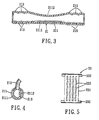
- the first conduit 21 is made of a resilient material, and has left and right end portions 210, and an intermediate portion 211 between the left and right end portions 210.
- Each of the left and right end portions 210 has a plurality of first annular bulges 213 of arc-shaped cross section, and a plurality of valleys 215 each formed between two adjacent ones of the first annular bulges 213.
- Each valley 215 can be used as a reference for cutting off at least one of the first annular bulges 213 at each of the left and right end portions 210 of the first conduit 21, so that the length of the first conduit 21 can be adjusted to suit a patient.
- the intermediate portion 211 has a tubular wall with a cross section resembling the shape of a segment so that the tubular wall has a chordal wall section 2112 that is flat in a chordal direction, and an arc-shaped wall section 2111 opposite to the chordal wall section 2112.
- the chordal wall section 2112 extends axially between the left and right end portions 210, and is concaved gradually from the left and right end portions 210 to a midpart of the chordal wall section 2112 so that the chordal wall section 2112 does not pressurize the philtrum of a patient.
- a pair of nasal prongs 212 projects upwardly from the arc-shaped wall section 2111, and is adapted to be inserted into the nostrils of the patient.
- the arc-shaped wall section 2111 has a concaved surface 214 formed between the nasal prongs 212, and is adapted to abut against a bottom of the nose of the patient.
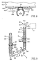
- Each of the second conduits 22 includes a corrugated tube 221, and a connecting tube 222 connected to a bottom end of the corrugated tube 221 and one of the left and right end portions 210 of the first conduit 21.
- the connecting tube 222 is angled into a substantially L-shaped configuration, and has a first end 223 formed with a second annular bulge 225 that mates rotatably with an outermost first annular bulge 213 at one of the left or right end portion of the first conduit 21, and a second end 224 opposite to the first end 223 and connected fluidly to the bottom end of the corrugated tube 221.
- first ends 223 of the connecting tubes 222 are configured to form the second annular bulges 225, respectively, that mate rotatably with the outermost first annular bulges 213 at the respective left and right end portions 210 of the first conduit 21, so that angular adjustment of the second conduits 22 relative to the first conduit 21 can be achieved.
- the fixing unit 24 includes two support frames 23, each of which includes a plate body 231, and two spaced-apart C-shaped clamps 232 that extend outwardly and respectively from top and bottom ends of the plate body 231 and that are disposed on a same one side of the plate body 231 to clamp the corrugated tube 221 of one of the second conduits 22.
- the other side of the plate body 231 is formed with an array of grooves 233 (see Fig. 5 ), the purpose of which is not only to minimize the amount of material needed for the plate body 231, but also to reduce frictional contact between the other side of the plate body 231 and a positioning surface of another component of the fixing unit 24, i.e., a head accessory 241 which will be described later in the description, and the static force.
- the fixing unit 24 further includes a head accessory 241, and two positioning members 242 (only one is visible in Fig. 7 ) disposed respectively on two opposite sides of the head accessory 241.
- the head accessory 241 is configured as headgear that is placed onto the head of the patient, and is made of a fabric material to enhance the degree of comfort during use of the head accessory or headgear 241.
- An elastic band may be provided on a loopedmarginal end243 of the headgear 241 to accommodate different patient head sizes.
- each of the positioning members 242 has a strap with two connecting ends 2421, 2422, and a mid-portion 2423 between the connecting ends 2421, 2422.
- the connecting end 2421 is fixed to the looped marginal end 243.
- the connecting end 2422 is connected releasably to the looped marginal end 243 through hook and loop fasteners (not shown) provided respectively on the connecting end 2422 and the looped marginal end 243 of the headgear 241.
- the mid-portion 2423 extends into the gap 234 (see Fig. 9 ) so as to confine the plate body 231 of the support frame 23 within a receiving space 245 cooperatively defined by the mid-portion 2423 and the looped marginal end 243 of the headgear 241.
- the respiratory auxiliary device 2 of the present invention is particularly suitable for use on a small child or infant, but is not limited thereto.
- the headgear 241 is then placed onto the head of a small child, as best shown in Fig. 7 .
- the nasal prongs 212 are inserted into the nostrils of the small child with the concaved surface 214 abutting against the bottom of the nose of the small child.
- each positioning member 242 passes through the gap 234, and engages releasably the looped marginal end 243 of the headgear 241, thereby quickly mounting the assembly of the first conduit 21, the corrugated tubes 221 and the connecting tubes 222 of the second conduits 22, and the support frames 23 to the head of the small child.
- the second conduit 22 that is connected to the left end portion 210 of the first conduit 21 (or the "left second conduit 22") is adapted to be connected to an air supply device (not shown) for supply of air to be inhaled by the small child via the first conduit 21 and the nasal prongs 212
- the second conduit 22 that is connected to the right end portion 210 of the first conduit 21 (or the "right second conduit 22") is adapted for discharging air exhaled by the small child and the excess air in the first conduit 21.
- a pressure-measuring device 3 may be connected to the right second conduit 22. Since the pressure-measuring device 3 is known in the art, a detailed description of the same is dispensed herewith.
- a pressure- measuring pipe 31 is disposed within the right second conduit 22, and has one end 311 extending into the first conduit 21 in proximity to the nasal prongs 212.
- the respiratory auxiliary device 2 further comprises a T-shaped connector 25 having a main tube 251 connected fluidly to the right second conduit 22, and a side tube 254 projecting transversely from the main tube 251.
- the main tube 251 has one end 253 connected to a top end of the corrugated tube 221 of the right second conduit 22, and the other end 250 opposite to the end 253 in an axial direction for discharging of air.
- the side tube 254 has an outer end 2541 adapted to be connected with the pressure-measuring device 3, and an inner end 2542 connected to the main tube 251.
- the T-shaped connector 25 further has an inner tube 252 disposed within the main tube 251, connected integrally to the inner end 2542 of the side tube 254, and bending from the inner end 2542 of the side tube 254 into the main tube 251 and partially out of the end 253 of the main tube 251 so as to connect with the other end 312 of the pressure-measuring pipe 31.
- the pressure-measuring pipe 31 is disposed stably within the right second conduit 22 through the T-shaped connector 25. This prevents the pressure-measuring pipe 31 from being entangled around the right second conduit 22, which could if the pressure-measuring pipe 31 was disposed externally of the right second conduit 22. Further, the end 311 of the pressure-measuring pipe 31 can be disposed closer to the nasal prongs 212, so that, in comparison with a conventional pressure-measuring method, the airflow pressure and the concentration of the carbon dioxide gas inside the tubes of the respiratory auxiliary device 2 can be measured more accurately.
- the bottom end of the corrugated tube 221 of the right second conduit 22 may be provided with a pressure valve (not shown) for adjusting suitably the pressure inside the tubes of the respiratory auxiliary device 2, thereby effectively preventing the formation of inappropriate pressure inside the tubes of the respiratory auxiliary device 2 which could bring discomfort to the small child during breathing.
- a pressure valve (not shown) for adjusting suitably the pressure inside the tubes of the respiratory auxiliary device 2, thereby effectively preventing the formation of inappropriate pressure inside the tubes of the respiratory auxiliary device 2 which could bring discomfort to the small child during breathing.
- the first conduit 21 ismade of a resilient material, and since the chordal wall section 2112 is concaved, the first conduit 21 is prevented from pressing against the philtrum of the small child and from suppressing the growth of facial skin tissues of the small child. Hence, the concave configuration of the chordal wall section 2112 does not inhibit the growth of facial skin tissues of the small child or infant. Moreover, because the chordal wall section 2112 is concaved, the position of the first conduit 21 can be fixed and the first conduit 21 can be prevented from turning due to an external force. Additionally, an outer surface of the chordal wall section 2112 has a matte finish surface, so that the outer surface of the chordal wall section 2112 is not slippery. As a result, the outer surface of the chordal wall section 2112 will not adhere to the skin of the small child or infant, which could hurt or injure the skin of the small child or infant.
- the two connecting ends 2421, 2422 of the positioning member 242 may be sewn to the looped marginal end 243 of the headgear 241, and the mid-portion 2423 has one end sewn to the looped marginal end 243 so that the receiving space 245 has a closed end 2451 and an open end 2452.
- the support frame 23 may be provided with only one C-shaped clamp 232 that extends outwardly from the top end of the plate body 2311 of the support frame 23. Through such a configuration, the plate body 2311 may be inserted into the receiving space 245 via the open end 2452. Hence, the support frame 23 can be similarly and easily positioned on the positioning member 242.
- the side of the plate body of each support frame 23 (see Fig. 2 ) that is opposite to the C-shaped clamps may be provided with a hook fastener (not shown), and the looped marginal end 243 (see Fig. 7 ) of the headgear may be provided with a loop fastener (not shown), so that the plate body of each support frame 23 may be directly connected to the looped marginal end 243 of the headgear through the hook and loop fasteners.
- the positioning member 242 may be dispensed herewith.
Applications Claiming Priority (1)
| Application Number | Priority Date | Filing Date | Title |
|---|---|---|---|
| TW097211749U TWM349271U (en) | 2008-07-02 | 2008-07-02 | Auxiliary device for breathing |
Publications (2)
| Publication Number | Publication Date |
|---|---|
| EP2140901A2 true EP2140901A2 (fr) | 2010-01-06 |
| EP2140901A3 EP2140901A3 (fr) | 2010-03-17 |
Family
ID=41112479
Family Applications (1)
| Application Number | Title | Priority Date | Filing Date |
|---|---|---|---|
| EP09008638A Withdrawn EP2140901A3 (fr) | 2008-07-02 | 2009-07-01 | Dispositif auxiliaire respiratoire |
Country Status (3)
| Country | Link |
|---|---|
| US (1) | US8511312B2 (fr) |
| EP (1) | EP2140901A3 (fr) |
| TW (1) | TWM349271U (fr) |
Cited By (5)
| Publication number | Priority date | Publication date | Assignee | Title |
|---|---|---|---|---|
| EP2578262A1 (fr) * | 2011-10-06 | 2013-04-10 | Heinen & Löwenstein GmbH & Co. KG | Distributeur d'oxygène utilisable dans le traitement par inhalation d'oxygène |
| CN104667398A (zh) * | 2015-01-29 | 2015-06-03 | 深圳市科曼医疗设备有限公司 | 呼吸机及其气道辅助装置 |
| WO2017182757A1 (fr) | 2016-04-22 | 2017-10-26 | Georges Boussignac | Cathéter de mesures mixtes pour sonde d'intubation respiratoire |
| TWI682792B (zh) * | 2019-01-30 | 2020-01-21 | 奇美醫療財團法人奇美醫院 | 供氧呼吸器防壓固定構造 |
| US20220409845A1 (en) * | 2008-06-05 | 2022-12-29 | ResMed Pty Ltd | Treatment of respiratory conditions |
Families Citing this family (6)
| Publication number | Priority date | Publication date | Assignee | Title |
|---|---|---|---|---|
| CA2757588C (fr) | 2009-04-02 | 2017-01-03 | Breathe Technologies, Inc. | Procedes, systemes et dispositifs de ventilation ouverte non invasive a l'aide d'ajutages de fourniture de gaz a l'air libre |
| TWI454294B (zh) * | 2009-08-03 | 2014-10-01 | Univ Nat Cheng Kung | 基於腦波訊號之呼吸輔助裝置及其方法 |
| CA3177429A1 (fr) | 2010-10-18 | 2012-04-26 | Fisher & Paykel Healthcare Limited | Canule nasale, conduit et systeme de fixation |
| TWI747175B (zh) * | 2011-04-08 | 2021-11-21 | 紐西蘭商費雪 & 佩凱爾關心健康有限公司 | 鼻套管、導管及固定系統 |
| WO2012160458A1 (fr) * | 2011-05-20 | 2012-11-29 | Koninklijke Philips Electronics N.V. | Mécanisme de fixation crânien pour un dispositif d'interface patient |
| CN107647999B (zh) * | 2017-10-23 | 2019-06-04 | 张洁 | 一种可防止儿童随意晃动的儿科专用手术治疗台 |
Citations (10)
| Publication number | Priority date | Publication date | Assignee | Title |
|---|---|---|---|---|
| US4774946A (en) * | 1983-11-28 | 1988-10-04 | Ackrad Laboratories, Inc. | Nasal and endotracheal tube apparatus |
| US4838258A (en) * | 1987-10-26 | 1989-06-13 | Gibeck-Dryden Corporation | Gas sampling lumen for breathing system |
| US4986269A (en) * | 1985-05-23 | 1991-01-22 | Etela-Hameen Keuhkovammayhdistys R.Y. | Respiration therapy apparatus |
| US5099836A (en) * | 1987-10-05 | 1992-03-31 | Hudson Respiratory Care Inc. | Intermittent oxygen delivery system and cannula |
| EP0505232A1 (fr) * | 1991-03-21 | 1992-09-23 | Taema | Installation de fourniture de surpression de gaz respiratoire et procédé de commande d'une telle installation |
| WO1995017220A1 (fr) * | 1993-12-21 | 1995-06-29 | Maersk Medical A/S | Dispositif servant a administrer de l'oxygene et/ou d'autres gaz a un patient |
| US5682881A (en) * | 1996-10-21 | 1997-11-04 | Winthrop; Neil | Nasal CPAP/Cannula and securement apparatus |
| FR2827778A1 (fr) * | 2001-07-30 | 2003-01-31 | Vygon | Appareil nasal d'assistance respiratoire |
| US20050033247A1 (en) * | 2003-08-06 | 2005-02-10 | Thompson Paul S. | Nasal cannula assembly |
| US20050139214A1 (en) * | 2003-10-28 | 2005-06-30 | Ngk Spark Plug Co., Ltd. | Oxygen concentrating apparatus |
Family Cites Families (7)
| Publication number | Priority date | Publication date | Assignee | Title |
|---|---|---|---|---|
| US4485822A (en) * | 1983-01-28 | 1984-12-04 | G & R Instrument Company, Inc. | Multi-phase interfacing system and method |
| US5400781A (en) * | 1993-08-03 | 1995-03-28 | Davenport; Richard A. | CO2 gas sampling mask having a bevelled sampling tube extending into the mask |
| US5617847A (en) * | 1995-10-12 | 1997-04-08 | Howe; Stephen L. | Assisted breathing apparatus and tubing therefore |
| US7066180B2 (en) * | 2003-07-09 | 2006-06-27 | Airmatrix Technologies, Inc. | Method and system for measuring airflow of nares |
| US20080099012A1 (en) * | 2004-10-08 | 2008-05-01 | Johnson Mark R | Snorkel clip |
| US7823585B2 (en) * | 2004-10-08 | 2010-11-02 | Mark Johnson | Snorkel clip |
| US9962512B2 (en) * | 2009-04-02 | 2018-05-08 | Breathe Technologies, Inc. | Methods, systems and devices for non-invasive ventilation including a non-sealing ventilation interface with a free space nozzle feature |
-
2008
- 2008-07-02 TW TW097211749U patent/TWM349271U/zh not_active IP Right Cessation
-
2009
- 2009-06-29 US US12/493,413 patent/US8511312B2/en active Active
- 2009-07-01 EP EP09008638A patent/EP2140901A3/fr not_active Withdrawn
Patent Citations (10)
| Publication number | Priority date | Publication date | Assignee | Title |
|---|---|---|---|---|
| US4774946A (en) * | 1983-11-28 | 1988-10-04 | Ackrad Laboratories, Inc. | Nasal and endotracheal tube apparatus |
| US4986269A (en) * | 1985-05-23 | 1991-01-22 | Etela-Hameen Keuhkovammayhdistys R.Y. | Respiration therapy apparatus |
| US5099836A (en) * | 1987-10-05 | 1992-03-31 | Hudson Respiratory Care Inc. | Intermittent oxygen delivery system and cannula |
| US4838258A (en) * | 1987-10-26 | 1989-06-13 | Gibeck-Dryden Corporation | Gas sampling lumen for breathing system |
| EP0505232A1 (fr) * | 1991-03-21 | 1992-09-23 | Taema | Installation de fourniture de surpression de gaz respiratoire et procédé de commande d'une telle installation |
| WO1995017220A1 (fr) * | 1993-12-21 | 1995-06-29 | Maersk Medical A/S | Dispositif servant a administrer de l'oxygene et/ou d'autres gaz a un patient |
| US5682881A (en) * | 1996-10-21 | 1997-11-04 | Winthrop; Neil | Nasal CPAP/Cannula and securement apparatus |
| FR2827778A1 (fr) * | 2001-07-30 | 2003-01-31 | Vygon | Appareil nasal d'assistance respiratoire |
| US20050033247A1 (en) * | 2003-08-06 | 2005-02-10 | Thompson Paul S. | Nasal cannula assembly |
| US20050139214A1 (en) * | 2003-10-28 | 2005-06-30 | Ngk Spark Plug Co., Ltd. | Oxygen concentrating apparatus |
Cited By (7)
| Publication number | Priority date | Publication date | Assignee | Title |
|---|---|---|---|---|
| US20220409845A1 (en) * | 2008-06-05 | 2022-12-29 | ResMed Pty Ltd | Treatment of respiratory conditions |
| US11878123B2 (en) * | 2008-06-05 | 2024-01-23 | ResMed Pty Ltd | Treatment of respiratory conditions |
| EP2578262A1 (fr) * | 2011-10-06 | 2013-04-10 | Heinen & Löwenstein GmbH & Co. KG | Distributeur d'oxygène utilisable dans le traitement par inhalation d'oxygène |
| CN104667398A (zh) * | 2015-01-29 | 2015-06-03 | 深圳市科曼医疗设备有限公司 | 呼吸机及其气道辅助装置 |
| WO2017182757A1 (fr) | 2016-04-22 | 2017-10-26 | Georges Boussignac | Cathéter de mesures mixtes pour sonde d'intubation respiratoire |
| FR3050381A1 (fr) * | 2016-04-22 | 2017-10-27 | Georges Boussignac | Catheter de mesures mixtes pour sonde d'intubation respiratoire |
| TWI682792B (zh) * | 2019-01-30 | 2020-01-21 | 奇美醫療財團法人奇美醫院 | 供氧呼吸器防壓固定構造 |
Also Published As
| Publication number | Publication date |
|---|---|
| TWM349271U (en) | 2009-01-21 |
| EP2140901A3 (fr) | 2010-03-17 |
| US20100000545A1 (en) | 2010-01-07 |
| US8511312B2 (en) | 2013-08-20 |
Similar Documents
| Publication | Publication Date | Title |
|---|---|---|
| US8511312B2 (en) | Respiratory auxiliary device | |
| US11565067B2 (en) | Asymmetrical nasal delivery elements and fittings for nasal interfaces | |
| JP6783331B2 (ja) | 患者用インタフェース及びヘッドギア | |
| US10842957B2 (en) | Nasal assembly | |
| JP6742289B2 (ja) | 鼻用インターフェイス | |
| JP6356756B2 (ja) | フレームを有する人間工学に基づいた調節可能な呼吸用マスクアセンブリ | |
| US8522785B2 (en) | Inextensible headgear and CPAP or ventilator mask assembly with the same | |
| US20060090760A1 (en) | Release mechanism for masks | |
| US20170151406A1 (en) | Oxygenation mask with integrated end-tidal carbon dioxide monitoring | |
| US10441737B2 (en) | Strapless nasal interface device | |
| CN211705566U (zh) | 新型吸氧面罩 | |
| US20230277795A1 (en) | Headgear Assembly for Securing a Fluid Tube | |
| AU2007221908A1 (en) | Release Mechanism for Masks | |
| EP3727275A1 (fr) | Dispositif inter-facial nasal sans sangle |
Legal Events
| Date | Code | Title | Description |
|---|---|---|---|
| PUAI | Public reference made under article 153(3) epc to a published international application that has entered the european phase |
Free format text: ORIGINAL CODE: 0009012 |
|
| AK | Designated contracting states |
Kind code of ref document: A2 Designated state(s): AT BE BG CH CY CZ DE DK EE ES FI FR GB GR HR HU IE IS IT LI LT LU LV MC MK MT NL NO PL PT RO SE SI SK SM TR |
|
| PUAL | Search report despatched |
Free format text: ORIGINAL CODE: 0009013 |
|
| AK | Designated contracting states |
Kind code of ref document: A3 Designated state(s): AT BE BG CH CY CZ DE DK EE ES FI FR GB GR HR HU IE IS IT LI LT LU LV MC MK MT NL NO PL PT RO SE SI SK SM TR |
|
| AX | Request for extension of the european patent |
Extension state: AL BA RS |
|
| STAA | Information on the status of an ep patent application or granted ep patent |
Free format text: STATUS: THE APPLICATION IS DEEMED TO BE WITHDRAWN |
|
| 18D | Application deemed to be withdrawn |
Effective date: 20100918 |