EP2140780B1 - Table - Google Patents
Table Download PDFInfo
- Publication number
- EP2140780B1 EP2140780B1 EP09008534A EP09008534A EP2140780B1 EP 2140780 B1 EP2140780 B1 EP 2140780B1 EP 09008534 A EP09008534 A EP 09008534A EP 09008534 A EP09008534 A EP 09008534A EP 2140780 B1 EP2140780 B1 EP 2140780B1
- Authority
- EP
- European Patent Office
- Prior art keywords
- fixing device
- table top
- leg
- fixing
- disposed
- Prior art date
- Legal status (The legal status is an assumption and is not a legal conclusion. Google has not performed a legal analysis and makes no representation as to the accuracy of the status listed.)
- Not-in-force
Links
- 230000008878 coupling Effects 0.000 claims abstract description 10
- 238000010168 coupling process Methods 0.000 claims abstract description 10
- 238000005859 coupling reaction Methods 0.000 claims abstract description 10
- 239000000463 material Substances 0.000 claims description 14
- 238000004026 adhesive bonding Methods 0.000 claims description 4
- 125000006850 spacer group Chemical group 0.000 claims description 4
- 239000002344 surface layer Substances 0.000 description 4
- 230000000712 assembly Effects 0.000 description 2
- 238000000429 assembly Methods 0.000 description 2
- 239000011248 coating agent Substances 0.000 description 2
- 238000000576 coating method Methods 0.000 description 2
- 239000011324 bead Substances 0.000 description 1
- 230000015572 biosynthetic process Effects 0.000 description 1
- 239000011093 chipboard Substances 0.000 description 1
- 238000005253 cladding Methods 0.000 description 1
- 230000000295 complement effect Effects 0.000 description 1
- 238000010276 construction Methods 0.000 description 1
- 238000004512 die casting Methods 0.000 description 1
- 238000005516 engineering process Methods 0.000 description 1
- 239000011888 foil Substances 0.000 description 1
- 238000001746 injection moulding Methods 0.000 description 1
- 239000004922 lacquer Substances 0.000 description 1
- 229910001092 metal group alloy Inorganic materials 0.000 description 1
- 238000000034 method Methods 0.000 description 1
- 238000012986 modification Methods 0.000 description 1
- 230000004048 modification Effects 0.000 description 1
- 239000000123 paper Substances 0.000 description 1
- 239000011087 paperboard Substances 0.000 description 1
- 230000003014 reinforcing effect Effects 0.000 description 1
- 239000007787 solid Substances 0.000 description 1
- 239000000243 solution Substances 0.000 description 1
- 230000003313 weakening effect Effects 0.000 description 1
- 239000002023 wood Substances 0.000 description 1
Images

Classifications
-
- A—HUMAN NECESSITIES
- A47—FURNITURE; DOMESTIC ARTICLES OR APPLIANCES; COFFEE MILLS; SPICE MILLS; SUCTION CLEANERS IN GENERAL
- A47B—TABLES; DESKS; OFFICE FURNITURE; CABINETS; DRAWERS; GENERAL DETAILS OF FURNITURE
- A47B13/00—Details of tables or desks
- A47B13/02—Underframes
- A47B13/023—Underframes with a central column
-
- A—HUMAN NECESSITIES
- A47—FURNITURE; DOMESTIC ARTICLES OR APPLIANCES; COFFEE MILLS; SPICE MILLS; SUCTION CLEANERS IN GENERAL
- A47B—TABLES; DESKS; OFFICE FURNITURE; CABINETS; DRAWERS; GENERAL DETAILS OF FURNITURE
- A47B13/00—Details of tables or desks
- A47B13/003—Connecting table tops to underframes
-
- A—HUMAN NECESSITIES
- A47—FURNITURE; DOMESTIC ARTICLES OR APPLIANCES; COFFEE MILLS; SPICE MILLS; SUCTION CLEANERS IN GENERAL
- A47B—TABLES; DESKS; OFFICE FURNITURE; CABINETS; DRAWERS; GENERAL DETAILS OF FURNITURE
- A47B13/00—Details of tables or desks
- A47B13/02—Underframes
- A47B13/021—Fastening devices of the feet or legs
Definitions
- the present invention relates to a table comprising a table top of a predetermined thickness, at least one vertically adjustable leg with a vertical adjustment device and at least one fixing device for fixing the leg to the table top, the fixing device being designed so as to be at least partly recessed from beneath into and secured to the table top.
- Vertically adjustable tables are known in numerous different versions. Thus, the number of legs may vary from a single, powerfully dimensioned central column to two or perhaps even four separate legs. Vertical adjustment takes place by means of adjustment devices integrated in the legs which may be operated either manually or electrically.
- the drive motor is integrated in the leg or the legs. Power for the drive motor is taken from the mains via a transformer.
- U1 is disclosed a table having a table top on a number of legs, the table top has an upper panel element and a lower panel element and therebetween a filling material.
- Each leg has a mounting device with movable clamping jaws to engage in corresponding openings in a fastening unit comprising a fixing element and one intermediate element. The fixing and intermediate elements are screwed together.
- the fastening unit is countersunk from below into the table top and the upper surface of the fastening unit is glued to the lower surface of the upper panel.
- This table has a table top supported on a base having two telescopic legs, the lower legs being inter-connected by means of a horizontal beam. Both the upper legs have on top thereof actuating assemblies comprising drive motors for operating a screw jack in each leg.
- the drive assemblies are mounted on the lower surface of the table top. Also mounted and extending downwardly the lower surface of the table top arc a motor control unit and an operator control.
- the present invention has for its object to improve the table intimated by way of introduction such that the drawback inherent in the prior art technology arc obviated.
- the present invention has for its object to design the table such that, taking as the point of departure a table top and components mounted thereon, it is possible to optionally retrofit one of several alternative legs.
- the present invention also has for its object to design the table so that its underside will, as far as possible, be free of wiring and other devices.
- the table intimated by way of introduction is characterised in that the drive motor is disposed in the fixing device and that the leg is fixable in the fixing device and its vertical adjustment device connectable to the drive motor.
- reference numeral 1 relates to a table top or a part thereof, reference numeral 2 to a vertically adjustable furniture leg and reference numeral 3 to an anchorage for fixing the furniture leg to the table top 1.
- table top 1 this may be of any optional shape and any optional dimensions apart from in one respect, namely its thickness.
- table tops with different surface materials and different designs in other respects, and which thereby may belong to a plurality of different furniture series, may be used according to the present invention.
- a table top 1 One common method of constructing a table top 1 entails that the table top, on its upper side, has an upper surface layer consisting of a panel material and on its underside of a lower surface layer, this also consisting of a panel material such as MDF panel or HDF panel. On the visible sides of the panel material, there is some suitable surface coating such as lacquer or paintwork, foil cladding, veneer or a coating consisting of a suitable high pressure laminate. Between the two surface layers, there is disposed a spacer material which is of low weight and which, for example, may consist or expanded plastic but may also consist of a fluted structure of paperboard or paper. The interconnection of the two surface layers and the spacer material takes place by gluing.
- a spacer material which is of low weight and which, for example, may consist or expanded plastic but may also consist of a fluted structure of paperboard or paper.
- Table tops of the type outlined here normally display a thickness of the order of magnitude of 50 mm, but lesser and greater thicknesses may also come into consideration.
- the furniture leg 2 has at least two mutually vertically adjustable sections, a lower section 4 and an upper section 5. How these sections arc guided in relation to one another is of no consequence according to the present invention, but one embodiment may be of the type illustrated in the Drawing, where both of the sections 4 and 5 are designed as tubular profiles of square cross section.
- This vertical adjustment device for adjustment of the relative positions between the two leg sections 4 and 5.
- This vertical adjustment device may, for example, be designed as a screw device, but may also include wires, chains or similar components.
- This vertical adjustment device is an integrated part of the furniture leg 2 proper and is fixedly mounted therein.
- the upper section 5 of the furniture leg 2 displays an anchorage in the form of a laterally projecting fixing flange 6. Regardless of how the rest of the furniture leg 2 is constructed and designed, this fixing flange 6 is standardized and thus has the same formation and dimensions on a plurality of different conceivable alternative furniture legs 2.
- the vertical adjustment device interiorly disposed in the furniture leg 2 has a drive coupling 7 (see Fig. 3 ) which, in the embodiment illustrated in the figures, is in the form of a drive shaft displaying, for example, polygonal cross section.
- the design is such that the drive shaft 7 may, in the axial direction, be inserted in a correspondingly, possibly complementary, designed recess.
- a fixing device which, in its entirety, carries reference numeral 8.
- This fixing device 8 is in the form of a box with an upper wall 9 and a circumferential wall 10.
- the fixing device may have a square or substantially rectangular design.
- a laterally projecting fixing surface 11 in the form of a projecting flange.
- the fixing device 8 is secured in the table top 1 in that it is at least partly countersunk from beneath and up into the material of the table top.
- the dimensioning is made in such a manner that the upper side of the upper wall 9 of the fixing device abuts against the lower side of the upper panel material of the table top and is fixedly glued in position there.
- the laterally projecting Fixing surface 11 of the fixing device 8 abuts against the underside of the lower panel material of the table top and is fixedly glued thereagainst.
- the spacer material which was in position in the region of the fixing device has been removed so that the fixing device is countersunk in the table top.
- the construction will be extremely strong and rigid and, because of the circumferential wall 10 of the fixing device 8, implies no local weakening of the table top.
- the distance between the upper side of the upper wall 9 and the upper side of the flange 11 is adapted such that gluing in position can take place.
- the fixing device 8 is dimensioned and designed in such a manner that there may be disposed therein a drive motor 12 and a reduction gear 13. Both of these components should be considered as components integrated in the fixing device.
- the reduction gear 13 may possibly be dispensed with.
- the reduction gear 13 has an output drive coupling 14 for cooperation with the drive coupling 7 of the furniture leg 2.
- the drive coupling is designed as a sleeve which per se may accommodate the shaft-shaped drive coupling 7 on the furniture leg and realise a rotational interconnection between them.
- the dimensions of the drive motor 12 and the reduction gear 13 are such that the fixing device 8 cannot display fully square configuration, but has an outward bulging 15 which accommodates a certain part of the drive motor 12.
- the outward bulging 15 also displays the above mentioned circumferential wall 10.
- the fixing device 8 is produced by injection moulding in plastic, die casting in a suitable metal alloy, or by other suitable means.
- the fixing elements of the fixing device 8 are formed as threaded bushings for accommodating corresponding screws which extend through apertures 16 in the fixing flange 6 of the furniture leg 2.
- the positioning and the mutual spacing between the fixing elements of the fixing device 8 and the furniture leg 2 are standardised so that one fixing device 8 can cooperate with any one furniture leg selected from among a plurality of different alternatives and otherwise differently designed furniture legs.
- the same relationship applies to both of the drive couplings 7 and 14 and their positioning in relation to the fixing elements so that any one optional furniture leg can always be interconnected to a fixing device 8.
- table top 1 of lightweight type, but other types of table tops may also be employed.
- table tops produced from solid wood, laminated board, different forms of panel material such as chipboard, MDF board, HDF board etc.
- the depth of the recess is adapted in such a manner that the upper wall 9 of the fixing device 8 may be glued against a corresponding surface in the bottom of the recess and the projecting flange 11 against the underside of the table top 1 or against the bottom of a recess therein.
- a mains-connected transformer For driving the drive motor 12, use is normally made of a mains-connected transformer. According to the present invention, this transformer is appropriately recessed in from beneath into the material of the table top 1 so that it does not encroach upon the space under the table.
- the wiring leads to the drive motor 12 are disposed to the fixing device 8, which thereby avoids more or less specifically adapted wiring to the different legs mounted on a table if the drive motor is mounted interiorly therein together with the vertical adjustment device.
Landscapes
- Tables And Desks Characterized By Structural Shape (AREA)
- Legs For Furniture In General (AREA)
Abstract
Description
- The present invention relates to a table comprising a table top of a predetermined thickness, at least one vertically adjustable leg with a vertical adjustment device and at least one fixing device for fixing the leg to the table top, the fixing device being designed so as to be at least partly recessed from beneath into and secured to the table top.
- Vertically adjustable tables are known in numerous different versions. Thus, the number of legs may vary from a single, powerfully dimensioned central column to two or perhaps even four separate legs. Vertical adjustment takes place by means of adjustment devices integrated in the legs which may be operated either manually or electrically.
- In the alternative involving electric operation, the drive motor is integrated in the leg or the legs. Power for the drive motor is taken from the mains via a transformer.
- In the alternative involving a plurality of legs, there arc moreover required control electronics which ensure that the drive motors in the different legs cause the legs to "march in step". Electrically operated legs moreover require extensive wiring on the underside of the table, and in addition wiring to the individual legs. This naturally implies that the underside of the table will become cluttered and that there are certain risks that, if a foreign object were to stand under a thus designed table when the table top is lowered so far that the object may come into contact with the wiring or components mounted on the underside of the table and possibly damage them.
- In
DE 20 2006 007 300 U1 is disclosed a table having a table top on a number of legs, the table top has an upper panel element and a lower panel element and therebetween a filling material. Each leg has a mounting device with movable clamping jaws to engage in corresponding openings in a fastening unit comprising a fixing element and one intermediate element. The fixing and intermediate elements are screwed together. The fastening unit is countersunk from below into the table top and the upper surface of the fastening unit is glued to the lower surface of the upper panel. - There is no means for adjusting the height of the table.
-
US 6 595 144 B1 describes a table having adjustable height. - This table has a table top supported on a base having two telescopic legs, the lower legs being inter-connected by means of a horizontal beam. Both the upper legs have on top thereof actuating assemblies comprising drive motors for operating a screw jack in each leg. The drive assemblies are mounted on the lower surface of the table top. Also mounted and extending downwardly the lower surface of the table top arc a motor control unit and an operator control.
- The present invention has for its object to improve the table intimated by way of introduction such that the drawback inherent in the prior art technology arc obviated. In particular, the present invention has for its object to design the table such that, taking as the point of departure a table top and components mounted thereon, it is possible to optionally retrofit one of several alternative legs. The present invention also has for its object to design the table so that its underside will, as far as possible, be free of wiring and other devices.
- The objects forming the basis of the present invention will be attained if the table intimated by way of introduction is characterised in that the drive motor is disposed in the fixing device and that the leg is fixable in the fixing device and its vertical adjustment device connectable to the drive motor.
- The present invention will now be described in greater detail hereinbelow, with reference to the accompanying Drawings. In the accompanying Drawings;
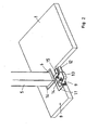
- Fig. 1
- is a perspective view from beneath of a part of a table top and a vertically adjustable leg according to the present invention mounted thereon;
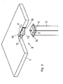
- Fig. 2
- is a view corresponding to that of
Fig. 1 , but with certain components cut away and presented as an exploded view; and - Fig. 3
- shows the device illustrated in
Fig. 2 seen obliquely from above. - Referring to the Drawings, in
Fig. 1 reference numeral 1 relates to a table top or a part thereof,reference numeral 2 to a vertically adjustable furniture leg andreference numeral 3 to an anchorage for fixing the furniture leg to thetable top 1. - As regards the
table top 1, this may be of any optional shape and any optional dimensions apart from in one respect, namely its thickness. Thus, a plurality of different table tops with different surface materials and different designs in other respects, and which thereby may belong to a plurality of different furniture series, may be used according to the present invention. - One common method of constructing a
table top 1 entails that the table top, on its upper side, has an upper surface layer consisting of a panel material and on its underside of a lower surface layer, this also consisting of a panel material such as MDF panel or HDF panel. On the visible sides of the panel material, there is some suitable surface coating such as lacquer or paintwork, foil cladding, veneer or a coating consisting of a suitable high pressure laminate. Between the two surface layers, there is disposed a spacer material which is of low weight and which, for example, may consist or expanded plastic but may also consist of a fluted structure of paperboard or paper. The interconnection of the two surface layers and the spacer material takes place by gluing. Along the periphery of the table top there is an edge bead or strip and possibly inside this a reinforcing framework. Table tops of the type outlined here normally display a thickness of the order of magnitude of 50 mm, but lesser and greater thicknesses may also come into consideration. - According to the present invention, the
furniture leg 2 has at least two mutually vertically adjustable sections, alower section 4 and anupper section 5. How these sections arc guided in relation to one another is of no consequence according to the present invention, but one embodiment may be of the type illustrated in the Drawing, where both of thesections - Interiorly in the
furniture leg 2, there is disposed a vertical adjustment device for adjustment of the relative positions between the twoleg sections furniture leg 2 proper and is fixedly mounted therein. - As is apparent principally from
Figs. 2 and3 , theupper section 5 of thefurniture leg 2 displays an anchorage in the form of a laterally projectingfixing flange 6. Regardless of how the rest of thefurniture leg 2 is constructed and designed, thisfixing flange 6 is standardized and thus has the same formation and dimensions on a plurality of different conceivablealternative furniture legs 2. - The vertical adjustment device interiorly disposed in the
furniture leg 2 has a drive coupling 7 (seeFig. 3 ) which, in the embodiment illustrated in the figures, is in the form of a drive shaft displaying, for example, polygonal cross section. The design is such that the drive shaft 7 may, in the axial direction, be inserted in a correspondingly, possibly complementary, designed recess. - For fixing the
furniture leg 2 on thetable top 1, use is made of a fixing device which, in its entirety, carriesreference numeral 8. Thisfixing device 8 is in the form of a box with anupper wall 9 and acircumferential wall 10. In one practical version, the fixing device may have a square or substantially rectangular design. Along the lower edge of thecircumferential wall 10, there is disposed a laterally projectingfixing surface 11 in the form of a projecting flange. - The
fixing device 8 is secured in thetable top 1 in that it is at least partly countersunk from beneath and up into the material of the table top. In the illustrated embodiment, the dimensioning is made in such a manner that the upper side of theupper wall 9 of the fixing device abuts against the lower side of the upper panel material of the table top and is fixedly glued in position there. Correspondingly, the laterally projectingFixing surface 11 of thefixing device 8 abuts against the underside of the lower panel material of the table top and is fixedly glued thereagainst. The spacer material which was in position in the region of the fixing device has been removed so that the fixing device is countersunk in the table top. As a result of large gluing surfaces, the construction will be extremely strong and rigid and, because of thecircumferential wall 10 of thefixing device 8, implies no local weakening of the table top. - Regardless of how the
fixing device 8 is recessed in thetable top 1, the distance between the upper side of theupper wall 9 and the upper side of theflange 11 is adapted such that gluing in position can take place. - The fixing
device 8 is dimensioned and designed in such a manner that there may be disposed therein adrive motor 12 and areduction gear 13. Both of these components should be considered as components integrated in the fixing device. - In certain cases, depending upon the design of the vertical adjustment device disposed in the
furniture leg 2, thereduction gear 13 may possibly be dispensed with. - In the embodiment illustrated on the Drawings, the
reduction gear 13 has anoutput drive coupling 14 for cooperation with the drive coupling 7 of thefurniture leg 2. In the illustrated embodiment, the drive coupling is designed as a sleeve which per se may accommodate the shaft-shaped drive coupling 7 on the furniture leg and realise a rotational interconnection between them. - In the illustrated embodiment, the dimensions of the
drive motor 12 and thereduction gear 13 are such that the fixingdevice 8 cannot display fully square configuration, but has an outward bulging 15 which accommodates a certain part of thedrive motor 12. The outward bulging 15 also displays the above mentionedcircumferential wall 10. Suitably, there may be provided in this outward bulge a cable passage for connection of an electric cable connected to thedrive motor 12. - In the transitional region between the
circumferential wall 10 of the fixingdevice 8 and the laterally projectingflange 11, there are provided fixing elements for interconnection with corresponding fixingelements 16 on thefurniture leg 2. In one practical version, the fixingdevice 8 is produced by injection moulding in plastic, die casting in a suitable metal alloy, or by other suitable means. Tn such embodiments, the fixing elements of the fixingdevice 8 are formed as threaded bushings for accommodating corresponding screws which extend throughapertures 16 in the fixingflange 6 of thefurniture leg 2. In such instance, the positioning and the mutual spacing between the fixing elements of the fixingdevice 8 and thefurniture leg 2 are standardised so that onefixing device 8 can cooperate with any one furniture leg selected from among a plurality of different alternatives and otherwise differently designed furniture legs. The same relationship applies to both of thedrive couplings 7 and 14 and their positioning in relation to the fixing elements so that any one optional furniture leg can always be interconnected to afixing device 8. - The present invention is not restricted to the above-described
table top 1 of lightweight type, but other types of table tops may also be employed. For example, table tops produced from solid wood, laminated board, different forms of panel material such as chipboard, MDF board, HDF board etc. - On making the recesses in which the
fixing device 8 is disposed, the depth of the recess is adapted in such a manner that theupper wall 9 of the fixingdevice 8 may be glued against a corresponding surface in the bottom of the recess and the projectingflange 11 against the underside of thetable top 1 or against the bottom of a recess therein. - For driving the
drive motor 12, use is normally made of a mains-connected transformer. According to the present invention, this transformer is appropriately recessed in from beneath into the material of thetable top 1 so that it does not encroach upon the space under the table. The wiring leads to thedrive motor 12 are disposed to thefixing device 8, which thereby avoids more or less specifically adapted wiring to the different legs mounted on a table if the drive motor is mounted interiorly therein together with the vertical adjustment device. - The present invention should not be considered as restricted to that described above and shown on the Drawings, many modifications being conceivable without departing from the scope of the appended Claims.
Claims (7)
- A table comprising a table top (1) of a predetermined thickness, with at least one vertically adjustable leg (2) with a vertical adjustment device and at least one fixing device (8) for fixing the leg to the table top, the fixing device (8) being designed so as to be at least partly recessed from beneath into and secured in the table top (1), characterised in that a drive motor (12) is disposed in the fixing device (8), and that the leg (2) is fixable in the fixing device and its vertical adjustment device (7, 14) connectable to the drive motor.
- The table as claimed in Claim 1, where the table top (1) has an upper panel, a lower panel and a spacer material therebetween, characterised in that the fixing device (8) has an upper surface (9) which is disposed to be connected to the upper panel, and an anchorage surface (11) which is disposed at its lower end and is laterally projecting and which is disposed to be interconnected to the lower panel.
- The table as claimed in Claim 2, characterised in that the upper surface (9) of the fixing device (8) as well as the anchorage surface (11) arc secured in each respective panel by gluing.
- The table as claimed in any of Claims 1 to 3, characterised in that a reduction gear (13) is disposed in the fixing device (8), that the reduction gear has coupling means (14) and that the leg (2) has a corresponding coupling means (7) for positive interconnection with the coupling means (14) of the reduction gear.
- The table as claimed in any of Claims 2 to 4, characterised in that the distance between the upper surface (9) of the fixing device (8) and the anchorage surface (11) substantially coincides with the thickness of the table top (1).
- The table as claimed in any of Claims 2 to 5, characterised in that the fixing device (8) is in the form of a box with a circumferential wall (10) between the upper surface (9) and the anchorage surface (11), and that there is disposed, in the region of the anchorage surface and the circumferential wall, fixing means for cooperation with corresponding fixing means (16) on the leg.
- The table as claimed in any of Claims 4 to 6, characterised in that the fixing device (8), the drive motor (12) and the gear (13) form an integrated unit.
Applications Claiming Priority (1)
| Application Number | Priority Date | Filing Date | Title |
|---|---|---|---|
| SE0801614A SE532645C2 (en) | 2008-07-04 | 2008-07-04 | Table |
Publications (2)
| Publication Number | Publication Date |
|---|---|
| EP2140780A1 EP2140780A1 (en) | 2010-01-06 |
| EP2140780B1 true EP2140780B1 (en) | 2012-04-18 |
Family
ID=41137681
Family Applications (1)
| Application Number | Title | Priority Date | Filing Date |
|---|---|---|---|
| EP09008534A Not-in-force EP2140780B1 (en) | 2008-07-04 | 2009-06-30 | Table |
Country Status (3)
| Country | Link |
|---|---|
| EP (1) | EP2140780B1 (en) |
| AT (1) | ATE553670T1 (en) |
| SE (1) | SE532645C2 (en) |
Families Citing this family (3)
| Publication number | Priority date | Publication date | Assignee | Title |
|---|---|---|---|---|
| USD659426S1 (en) | 2011-04-22 | 2012-05-15 | Steelcase Inc. | Furniture piece |
| EP3624639A1 (en) | 2017-05-15 | 2020-03-25 | Actiforce International B.V. | Table with top of variable height |
| DE102018110261A1 (en) | 2018-04-27 | 2019-10-31 | Yaasa Living Ag | Table top, base and worktable with a table top and feet |
Family Cites Families (4)
| Publication number | Priority date | Publication date | Assignee | Title |
|---|---|---|---|---|
| US6595144B1 (en) * | 2000-05-17 | 2003-07-22 | Suspa Incorporated | Adjustable leg assembly |
| US6435048B1 (en) * | 2001-02-02 | 2002-08-20 | Suspa Incorporated | Multi-leg telescopic linear actuator |
| SE527764C2 (en) * | 2004-10-19 | 2006-05-30 | Oestergrens Elmotor Ab | Height adjustable furniture and method of raising and lowering height adjustable furniture |
| DE202006007300U1 (en) * | 2006-05-05 | 2007-09-06 | Hettich-Heinze Gmbh & Co. Kg | Connecting device for furniture |
-
2008
- 2008-07-04 SE SE0801614A patent/SE532645C2/en not_active IP Right Cessation
-
2009
- 2009-06-30 AT AT09008534T patent/ATE553670T1/en active
- 2009-06-30 EP EP09008534A patent/EP2140780B1/en not_active Not-in-force
Also Published As
| Publication number | Publication date |
|---|---|
| EP2140780A1 (en) | 2010-01-06 |
| SE0801614L (en) | 2010-01-05 |
| SE532645C2 (en) | 2010-03-09 |
| ATE553670T1 (en) | 2012-05-15 |
Similar Documents
| Publication | Publication Date | Title |
|---|---|---|
| EP3440958B1 (en) | Motorized adjustable height table | |
| US11045933B2 (en) | Device for inserting a tongue | |
| AU2002365623B2 (en) | A lifting column, preferably for height adjustable tables and method for manufacturing thereof | |
| US9703278B2 (en) | Electrical actuator system for adjustable furniture with control box having ports in opposing walls | |
| EP2823731B1 (en) | Vertically adjustable table construction | |
| US6676231B1 (en) | Modular furniture system | |
| CN101835404A (en) | Table | |
| EP3942967B1 (en) | Kit comprising an adjustable leg | |
| EP2140780A1 (en) | Table | |
| KR101037276B1 (en) | Packing box with reinforced corners and packing box manufacturing apparatus for manufacturing the same | |
| US8056489B2 (en) | Telescopic column, especially for height adjustable tables | |
| KR101688694B1 (en) | Lift table | |
| EP4110139A1 (en) | Sheet for assembling a drawer | |
| DE102007034818A1 (en) | Platform system to operate as a rotating/navigable device adapts to a wide range of uses as a piece of furniture, a desk, an office tool or a piece of kitchen furniture | |
| JP5532757B2 (en) | Cabinet equipment | |
| HK40000307A (en) | Motorized adjustable height table | |
| KR101564873B1 (en) | Desk | |
| CN108045094B (en) | Low-resistance double-power-operated ink stack of pictorial machine | |
| EP1815085A1 (en) | Support structure for elevated floor assembly | |
| CN210452996U (en) | Environment-friendly polymer automotive interior sheet drilling equipment who makes things convenient for location | |
| JP2018171134A (en) | Lightweight base plate unit | |
| CN209324812U (en) | Laminating frock for sound-insulating cotton for automobile spare tire cover | |
| JP6855260B2 (en) | Connection structure and fixtures | |
| EP1335139A1 (en) | Substructure for height adjustable table | |
| CN219041211U (en) | Frock is used in cubical switchboard equipment |
Legal Events
| Date | Code | Title | Description |
|---|---|---|---|
| PUAI | Public reference made under article 153(3) epc to a published international application that has entered the european phase |
Free format text: ORIGINAL CODE: 0009012 |
|
| AK | Designated contracting states |
Kind code of ref document: A1 Designated state(s): AT BE BG CH CY CZ DE DK EE ES FI FR GB GR HR HU IE IS IT LI LT LU LV MC MK MT NL NO PL PT RO SE SI SK TR |
|
| 17P | Request for examination filed |
Effective date: 20100706 |
|
| GRAP | Despatch of communication of intention to grant a patent |
Free format text: ORIGINAL CODE: EPIDOSNIGR1 |
|
| GRAS | Grant fee paid |
Free format text: ORIGINAL CODE: EPIDOSNIGR3 |
|
| GRAA | (expected) grant |
Free format text: ORIGINAL CODE: 0009210 |
|
| AK | Designated contracting states |
Kind code of ref document: B1 Designated state(s): AT BE BG CH CY CZ DE DK EE ES FI FR GB GR HR HU IE IS IT LI LT LU LV MC MK MT NL NO PL PT RO SE SI SK TR |
|
| REG | Reference to a national code |
Ref country code: GB Ref legal event code: FG4D |
|
| REG | Reference to a national code |
Ref country code: CH Ref legal event code: EP |
|
| REG | Reference to a national code |
Ref country code: IE Ref legal event code: FG4D |
|
| REG | Reference to a national code |
Ref country code: AT Ref legal event code: REF Ref document number: 553670 Country of ref document: AT Kind code of ref document: T Effective date: 20120515 |
|
| REG | Reference to a national code |
Ref country code: DE Ref legal event code: R096 Ref document number: 602009006305 Country of ref document: DE Effective date: 20120621 |
|
| REG | Reference to a national code |
Ref country code: NL Ref legal event code: VDEP Effective date: 20120418 |
|
| REG | Reference to a national code |
Ref country code: AT Ref legal event code: MK05 Ref document number: 553670 Country of ref document: AT Kind code of ref document: T Effective date: 20120418 |
|
| LTIE | Lt: invalidation of european patent or patent extension |
Effective date: 20120418 |
|
| PG25 | Lapsed in a contracting state [announced via postgrant information from national office to epo] |
Ref country code: FI Free format text: LAPSE BECAUSE OF FAILURE TO SUBMIT A TRANSLATION OF THE DESCRIPTION OR TO PAY THE FEE WITHIN THE PRESCRIBED TIME-LIMIT Effective date: 20120418 Ref country code: IS Free format text: LAPSE BECAUSE OF FAILURE TO SUBMIT A TRANSLATION OF THE DESCRIPTION OR TO PAY THE FEE WITHIN THE PRESCRIBED TIME-LIMIT Effective date: 20120818 Ref country code: CY Free format text: LAPSE BECAUSE OF FAILURE TO SUBMIT A TRANSLATION OF THE DESCRIPTION OR TO PAY THE FEE WITHIN THE PRESCRIBED TIME-LIMIT Effective date: 20120418 Ref country code: LT Free format text: LAPSE BECAUSE OF FAILURE TO SUBMIT A TRANSLATION OF THE DESCRIPTION OR TO PAY THE FEE WITHIN THE PRESCRIBED TIME-LIMIT Effective date: 20120418 Ref country code: PL Free format text: LAPSE BECAUSE OF FAILURE TO SUBMIT A TRANSLATION OF THE DESCRIPTION OR TO PAY THE FEE WITHIN THE PRESCRIBED TIME-LIMIT Effective date: 20120418 Ref country code: NO Free format text: LAPSE BECAUSE OF FAILURE TO SUBMIT A TRANSLATION OF THE DESCRIPTION OR TO PAY THE FEE WITHIN THE PRESCRIBED TIME-LIMIT Effective date: 20120718 Ref country code: SE Free format text: LAPSE BECAUSE OF FAILURE TO SUBMIT A TRANSLATION OF THE DESCRIPTION OR TO PAY THE FEE WITHIN THE PRESCRIBED TIME-LIMIT Effective date: 20120418 |
|
| PG25 | Lapsed in a contracting state [announced via postgrant information from national office to epo] |
Ref country code: SI Free format text: LAPSE BECAUSE OF FAILURE TO SUBMIT A TRANSLATION OF THE DESCRIPTION OR TO PAY THE FEE WITHIN THE PRESCRIBED TIME-LIMIT Effective date: 20120418 Ref country code: HR Free format text: LAPSE BECAUSE OF FAILURE TO SUBMIT A TRANSLATION OF THE DESCRIPTION OR TO PAY THE FEE WITHIN THE PRESCRIBED TIME-LIMIT Effective date: 20120418 Ref country code: LV Free format text: LAPSE BECAUSE OF FAILURE TO SUBMIT A TRANSLATION OF THE DESCRIPTION OR TO PAY THE FEE WITHIN THE PRESCRIBED TIME-LIMIT Effective date: 20120418 Ref country code: PT Free format text: LAPSE BECAUSE OF FAILURE TO SUBMIT A TRANSLATION OF THE DESCRIPTION OR TO PAY THE FEE WITHIN THE PRESCRIBED TIME-LIMIT Effective date: 20120820 Ref country code: GR Free format text: LAPSE BECAUSE OF FAILURE TO SUBMIT A TRANSLATION OF THE DESCRIPTION OR TO PAY THE FEE WITHIN THE PRESCRIBED TIME-LIMIT Effective date: 20120719 |
|
| PG25 | Lapsed in a contracting state [announced via postgrant information from national office to epo] |
Ref country code: BE Free format text: LAPSE BECAUSE OF FAILURE TO SUBMIT A TRANSLATION OF THE DESCRIPTION OR TO PAY THE FEE WITHIN THE PRESCRIBED TIME-LIMIT Effective date: 20120418 |
|
| PG25 | Lapsed in a contracting state [announced via postgrant information from national office to epo] |
Ref country code: NL Free format text: LAPSE BECAUSE OF FAILURE TO SUBMIT A TRANSLATION OF THE DESCRIPTION OR TO PAY THE FEE WITHIN THE PRESCRIBED TIME-LIMIT Effective date: 20120418 Ref country code: AT Free format text: LAPSE BECAUSE OF FAILURE TO SUBMIT A TRANSLATION OF THE DESCRIPTION OR TO PAY THE FEE WITHIN THE PRESCRIBED TIME-LIMIT Effective date: 20120418 Ref country code: MC Free format text: LAPSE BECAUSE OF NON-PAYMENT OF DUE FEES Effective date: 20120630 Ref country code: SK Free format text: LAPSE BECAUSE OF FAILURE TO SUBMIT A TRANSLATION OF THE DESCRIPTION OR TO PAY THE FEE WITHIN THE PRESCRIBED TIME-LIMIT Effective date: 20120418 Ref country code: DK Free format text: LAPSE BECAUSE OF FAILURE TO SUBMIT A TRANSLATION OF THE DESCRIPTION OR TO PAY THE FEE WITHIN THE PRESCRIBED TIME-LIMIT Effective date: 20120418 Ref country code: EE Free format text: LAPSE BECAUSE OF FAILURE TO SUBMIT A TRANSLATION OF THE DESCRIPTION OR TO PAY THE FEE WITHIN THE PRESCRIBED TIME-LIMIT Effective date: 20120418 Ref country code: CZ Free format text: LAPSE BECAUSE OF FAILURE TO SUBMIT A TRANSLATION OF THE DESCRIPTION OR TO PAY THE FEE WITHIN THE PRESCRIBED TIME-LIMIT Effective date: 20120418 Ref country code: RO Free format text: LAPSE BECAUSE OF FAILURE TO SUBMIT A TRANSLATION OF THE DESCRIPTION OR TO PAY THE FEE WITHIN THE PRESCRIBED TIME-LIMIT Effective date: 20120418 |
|
| PLBE | No opposition filed within time limit |
Free format text: ORIGINAL CODE: 0009261 |
|
| STAA | Information on the status of an ep patent application or granted ep patent |
Free format text: STATUS: NO OPPOSITION FILED WITHIN TIME LIMIT |
|
| PG25 | Lapsed in a contracting state [announced via postgrant information from national office to epo] |
Ref country code: IT Free format text: LAPSE BECAUSE OF FAILURE TO SUBMIT A TRANSLATION OF THE DESCRIPTION OR TO PAY THE FEE WITHIN THE PRESCRIBED TIME-LIMIT Effective date: 20120418 Ref country code: MK Free format text: LAPSE BECAUSE OF FAILURE TO SUBMIT A TRANSLATION OF THE DESCRIPTION OR TO PAY THE FEE WITHIN THE PRESCRIBED TIME-LIMIT Effective date: 20120418 |
|
| 26N | No opposition filed |
Effective date: 20130121 |
|
| REG | Reference to a national code |
Ref country code: IE Ref legal event code: MM4A |
|
| REG | Reference to a national code |
Ref country code: FR Ref legal event code: ST Effective date: 20130228 |
|
| REG | Reference to a national code |
Ref country code: DE Ref legal event code: R119 Ref document number: 602009006305 Country of ref document: DE Effective date: 20130101 |
|
| PG25 | Lapsed in a contracting state [announced via postgrant information from national office to epo] |
Ref country code: DE Free format text: LAPSE BECAUSE OF NON-PAYMENT OF DUE FEES Effective date: 20130101 Ref country code: FR Free format text: LAPSE BECAUSE OF NON-PAYMENT OF DUE FEES Effective date: 20120702 Ref country code: IE Free format text: LAPSE BECAUSE OF NON-PAYMENT OF DUE FEES Effective date: 20120630 |
|
| PG25 | Lapsed in a contracting state [announced via postgrant information from national office to epo] |
Ref country code: MT Free format text: LAPSE BECAUSE OF FAILURE TO SUBMIT A TRANSLATION OF THE DESCRIPTION OR TO PAY THE FEE WITHIN THE PRESCRIBED TIME-LIMIT Effective date: 20120418 Ref country code: BG Free format text: LAPSE BECAUSE OF FAILURE TO SUBMIT A TRANSLATION OF THE DESCRIPTION OR TO PAY THE FEE WITHIN THE PRESCRIBED TIME-LIMIT Effective date: 20120718 |
|
| PG25 | Lapsed in a contracting state [announced via postgrant information from national office to epo] |
Ref country code: ES Free format text: LAPSE BECAUSE OF FAILURE TO SUBMIT A TRANSLATION OF THE DESCRIPTION OR TO PAY THE FEE WITHIN THE PRESCRIBED TIME-LIMIT Effective date: 20120729 |
|
| REG | Reference to a national code |
Ref country code: CH Ref legal event code: PL |
|
| GBPC | Gb: european patent ceased through non-payment of renewal fee |
Effective date: 20130630 |
|
| PG25 | Lapsed in a contracting state [announced via postgrant information from national office to epo] |
Ref country code: GB Free format text: LAPSE BECAUSE OF NON-PAYMENT OF DUE FEES Effective date: 20130630 Ref country code: CH Free format text: LAPSE BECAUSE OF NON-PAYMENT OF DUE FEES Effective date: 20130630 Ref country code: LI Free format text: LAPSE BECAUSE OF NON-PAYMENT OF DUE FEES Effective date: 20130630 Ref country code: TR Free format text: LAPSE BECAUSE OF FAILURE TO SUBMIT A TRANSLATION OF THE DESCRIPTION OR TO PAY THE FEE WITHIN THE PRESCRIBED TIME-LIMIT Effective date: 20120418 |
|
| PG25 | Lapsed in a contracting state [announced via postgrant information from national office to epo] |
Ref country code: LU Free format text: LAPSE BECAUSE OF NON-PAYMENT OF DUE FEES Effective date: 20120630 |
|
| PG25 | Lapsed in a contracting state [announced via postgrant information from national office to epo] |
Ref country code: HU Free format text: LAPSE BECAUSE OF FAILURE TO SUBMIT A TRANSLATION OF THE DESCRIPTION OR TO PAY THE FEE WITHIN THE PRESCRIBED TIME-LIMIT Effective date: 20090630 |