EP2140522B1 - Electrical connector comprising a mat seal - Google Patents
Electrical connector comprising a mat seal Download PDFInfo
- Publication number
- EP2140522B1 EP2140522B1 EP07735569A EP07735569A EP2140522B1 EP 2140522 B1 EP2140522 B1 EP 2140522B1 EP 07735569 A EP07735569 A EP 07735569A EP 07735569 A EP07735569 A EP 07735569A EP 2140522 B1 EP2140522 B1 EP 2140522B1
- Authority
- EP
- European Patent Office
- Prior art keywords
- mat seal
- electrical connector
- grid
- face
- mobile part
- Prior art date
- Legal status (The legal status is an assumption and is not a legal conclusion. Google has not performed a legal analysis and makes no representation as to the accuracy of the status listed.)
- Active
Links
Images


Classifications
-
- H—ELECTRICITY
- H01—ELECTRIC ELEMENTS
- H01R—ELECTRICALLY-CONDUCTIVE CONNECTIONS; STRUCTURAL ASSOCIATIONS OF A PLURALITY OF MUTUALLY-INSULATED ELECTRICAL CONNECTING ELEMENTS; COUPLING DEVICES; CURRENT COLLECTORS
- H01R13/00—Details of coupling devices of the kinds covered by groups H01R12/70 or H01R24/00 - H01R33/00
- H01R13/46—Bases; Cases
- H01R13/52—Dustproof, splashproof, drip-proof, waterproof, or flameproof cases
- H01R13/5213—Covers
-
- H—ELECTRICITY
- H01—ELECTRIC ELEMENTS
- H01R—ELECTRICALLY-CONDUCTIVE CONNECTIONS; STRUCTURAL ASSOCIATIONS OF A PLURALITY OF MUTUALLY-INSULATED ELECTRICAL CONNECTING ELEMENTS; COUPLING DEVICES; CURRENT COLLECTORS
- H01R13/00—Details of coupling devices of the kinds covered by groups H01R12/70 or H01R24/00 - H01R33/00
- H01R13/46—Bases; Cases
- H01R13/52—Dustproof, splashproof, drip-proof, waterproof, or flameproof cases
- H01R13/5205—Sealing means between cable and housing, e.g. grommet
- H01R13/5208—Sealing means between cable and housing, e.g. grommet having at least two cable receiving openings
-
- H—ELECTRICITY
- H01—ELECTRIC ELEMENTS
- H01R—ELECTRICALLY-CONDUCTIVE CONNECTIONS; STRUCTURAL ASSOCIATIONS OF A PLURALITY OF MUTUALLY-INSULATED ELECTRICAL CONNECTING ELEMENTS; COUPLING DEVICES; CURRENT COLLECTORS
- H01R13/00—Details of coupling devices of the kinds covered by groups H01R12/70 or H01R24/00 - H01R33/00
- H01R13/62—Means for facilitating engagement or disengagement of coupling parts or for holding them in engagement
- H01R13/629—Additional means for facilitating engagement or disengagement of coupling parts, e.g. aligning or guiding means, levers, gas pressure electrical locking indicators, manufacturing tolerances
- H01R13/62933—Comprising exclusively pivoting lever
- H01R13/62938—Pivoting lever comprising own camming means
Definitions
- the present invention relates to electrical connectors with a mat seal.
- EP-A1-1 296 415 describes an electrical connector of the type comprising :
- the insulative housing comprises a housing body and a contact carrier, able to slide on each other.
- the known electrical connector For assembling the known electrical connector, cables are introduced through the mat seal for accommodating the terminals in the accommodating chambers arranged in the contact carrier.
- the known electrical connector comprises rotatory lever system for locking the connector to a counterpart connector.
- the lever system is arranged so that, when activated, it brings the housing body closer to the contact carrier. The housing body thus drags along the rear grid so that the rear grid compresses the mat seal.
- the invention proposes an electrical connector arranged so that an alternative assembling is possible, permitting an easier bending of the cables.
- the electrical connector 10 is a male connector of a type used in automotive applications, intended to mate with a counterpart female connector.
- the electrical connector according to the invention could be a female connector intended to mate with a counterpart male connector.
- the electrical connector 10 comprises an insulative housing 12, usually made of a plastic material.
- the insulative housing 12 is essentially constituted of a parallelepiped having a front face 14 for being mated with a counterpart female electrical connector (not shown), and a rear face 16 (visible on figures 2 , 3 and 4 ) for inserting cable terminals (not shown).
- a plurality of accommodating chambers 18 are formed in the insulative housing 12. Each accommodating chamber 18 opens, first on the rear face 16 for inserting a respective cable terminal, and second on the front face 14 so that the respective cable terminal accommodated in the accommodating chamber 18 can be connected to a counterpart terminal (not shown), of the counterpart connector.
- a rear skirt 20 extends rearward with respect to the rear face 16.
- the rear skirt 20 is made integral with the housing 12, in a single molding process.
- the rear skirt 20 defines a substantially rectangular rear aperture 22, located opposite the insulative housing 12.
- the rear skirt 20 is provided with two ribs 24, located at two opposite sides of the rear aperture 22.
- the ribs 24 extend transversally relative to the XX' direction. Each rib 24 forms a guide rail for a rear cap 26. The ribs 24 project perpendicularly to the XX' axis, i.e. toward the sides of the electrical connector, so as to form a stop for the rear cap 26 in the XX' direction.
- the rear skirt 20 is also provided with complementary ribs 25 which also extend transversally relative to the XX' direction, but project along the XX' direction, toward the rear face 16 of the connector, so that the complementary ribs 25 form a lateral stop for the rear cap 26, preventing lateral displacement of the rear cap 26.
- the ribs 24 and the complementary ribs 25 are alternatively discontinuous. They complement each other, i.e. the discontinuity of the rib 24 corresponds to the presence of the rib 25. This permits their molding.
- the rear cap 26 is intended to be mounted on the rear skirt 20 so as to cover the rear aperture 22.
- the rear cap 26 comprises two lateral walls 26A provided with respective grooves 27 able to cooperate with the ribs 24 of the rear skirt 20.
- the rear cap 26 is opened on a side between the lateral walls 26A, so as to define a lateral cable entrance 28.
- the mat seal 30 is provided with a plurality of cable passages 32 facing the accommodating chambers 18.
- a clearance is provided laterally between the mat seal 30 and the rear skirt 20.
- the clearance between the rear skirt 20 and the mat seal 30 is from 0.15 to 0.4 millimeters. The clearance insures that no compression is induced on the mat seal 30 by the rear skirt 20. In this way, the cables may be inserted through the mat seal without deteriorating the mat seal 30, since the mat seal is not compressed. In other words, the clearance that is present when the mat seal is not compressed, allows the enlargement of the passages of the mat seal, when the cables are introduced.
- a rear grid 34 is also disposed in the rear skirt 20, against the mat seal 30.
- the rear grid 34 is provided with a plurality of cable passages facing the cable passages of the mat seal 30.
- the rear grid 34 is able to slide along the XX' axis in the rear skirt 20, so as to move forward towards the insulative housing, and in particular towards the rear face 16.
- each cable thus makes a bend inside the rear cap 26, before passing through the rear grid 34 then the mat seal 30, in order to reach an accommodating chamber 18, in which the terminal of the cable lies.
- the rear grid 34 comprises two opposite peripheral latches 36. Each latch 36 is intended to be received in a corresponding recess 38 arranged on the inner side 20A of the rear skirt 20.
- the recesses 38 form a stop for maintaining the rear grid 34 in a pre-locking position against the mat seal 30, via their cooperation with the latches 36.
- the pre-locking position is depicted on figures 1 and 2 . More precisely, the recesses 38 and the latches 36 prevent the rear grid 34 from moving rearward in the rear skirt 20, away from the rear face 20.
- the recesses 38 are placed in the XX' direction so that the rear grid 34 in the pre-locking position does not compress the mat seal 30.
- the cable passages 32 of the mat seal 30 are thus radially uncompressed, which allow an easy insertion/removing of the cables. Furthermore, the easy insertion/removing prevents deterioration of the mat seal.
- the rear grid 34 further comprises two opposite rear flanges 40.
- Each flange 40 projects rearward with respect to the rear grid 34, along the inner side 20A of the rear skirt 20.
- the flanges 40 are chamfered at each of their ends, so as to form ramps 42, see figures 1 and 2 .
- the flanges 40 are thus symmetrical.
- the flanges 40 are preferably made integral and moulded in a single process with the rear grid. The flanges 40 are thus fixed to the rear grid.
- the lateral walls 26A are provided with inner ribs 44 projecting towards the inside of the rear cap 26.
- the inner ribs 44 hit the ramps 42, which causes the rear grid 34 to slide along the XX' direction, toward the mat seal in the rear skirt 20, thus longitudinally compressing the mat seal 20 against the rear face 16 of the insulative housing 12 until an end position is attained. Since the flanges 30 are symmetrical, the rear cap 26 can be mounted from each extremity of the flanges.
- the two flanges 40 can be replaced by a similar but unique flange projecting rearward from a medium line of the rear grid 24 situated between two rows of cable passages and the ribs 44 being replaced by a unique rib projecting toward the grid from a top of the cover 24.
- the height of the flange 40 can be between 3 to 10 mm, preferentially between 4 to 5 mm.
- the rear cap is locked by using clipping means, such as latches provided on the rear cap, so as to enter corresponding holes provided in the housing 12.
- the mat seal is laterally confined by the rear skirt 20, so that the mat seal first extend against the rear skirt, i.e. until the clearance is filled up, then the passages shrink.
- the assembling of the connector 10 is easy, because the mounting of the rear cap 26 automatically induces the sealing of the cables pressing through the mat seal 20.
- the disassembling of the rear cap 26 will let the rear grid 24 free of moving rearward, thus allowing a spring back of the mat seal 20. In this way, the cables may be removed without deteriorating the mat seal 20, which then can be re-used.
- the invention is not limited by the previous described example.
- the electrical connector could only have one flange.
- the guide rails could be formed by grooves instead of ribs.
- the lateral walls of the rear cap would be provided with corresponding ribs.
Landscapes
- Connector Housings Or Holding Contact Members (AREA)
- Resistance Heating (AREA)
- Mattresses And Other Support Structures For Chairs And Beds (AREA)
Abstract
Description
- The present invention relates to electrical connectors with a mat seal.
-
EP-A1-1 296 415 describes an electrical connector of the type comprising : - an insulative housing having:
- a front face for being mated with a counterpart electrical connector, and
- a rear face for inserting cable terminals,
- a plurality of terminal accommodating chambers, which each open on the rear face for inserting of a respective cable terminal, and on the front face so that the respective cable terminal accommodated in the accommodating chamber can be connected to a counterpart terminal of the counterpart connector,
- a rear skirt extending rearward with respect to the rear face,
- a mat seal disposed in the rear skirt against the rear face, and having a plurality of cable passages facing the accommodating chambers,
- a rear grid, disposed in the rear skirt, against the mat seal, and having a plurality of cable passages facing the cable passages of the mat seal.
- In the known electrical connector, the insulative housing comprises a housing body and a contact carrier, able to slide on each other.
- For assembling the known electrical connector, cables are introduced through the mat seal for accommodating the terminals in the accommodating chambers arranged in the contact carrier. The known electrical connector comprises rotatory lever system for locking the connector to a counterpart connector. The lever system is arranged so that, when activated, it brings the housing body closer to the contact carrier. The housing body thus drags along the rear grid so that the rear grid compresses the mat seal.
- This longitudinal compression leads to a shrinking of the cable passages of the mat seal, so that efficient sealing with the cables are obtained.
- Document
JP 2005 123102 A - a mobile part,
- a guide rail fixed to the housing, the guide rail being transverse to the front-rear direction, for transversally guiding the mobile part,
- a ramp system such that, when the mobile part is guided by the guide rail, the ramp system pushes the rear grid against the mat seal so as to compress the mat seal.
- In this electrical connector, the mounting of the mobile part automatically leads to the compressing of the mat seal. In this way, the sealing of the cables occurs when the connector is assembled.
- The invention proposes an electrical connector arranged so that an alternative assembling is possible, permitting an easier bending of the cables.
- The invention will be better understood by reading the following description of a non limitative exemplary embodiment, referring to the drawings in which:
-
Figure 1 is tri-dimensional view of an electrical connector according to the invention, before being assembled. -
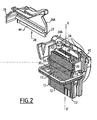
Figure 2 is a tri-dimensional cross-sectional view along the II plane offigure 1 , before the electrical connector is assembled. -
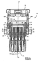
Figures 3 and4 are cross-sectional views along the III, IV plane offigure 1 , the electrical connector being assembled. - Turning to the figures, an
electrical connector 10 according to the invention is depicted. - The
electrical connector 10 is a male connector of a type used in automotive applications, intended to mate with a counterpart female connector. In an alternative embodiment, the electrical connector according to the invention could be a female connector intended to mate with a counterpart male connector. - For the sake of clarity, the figures are orientated according to an XX' axis, which stands for the mating direction. Every direction- or orientation related term in the following description, in particular the terms "rear" and "front", refer to the XX' axis.
- The
electrical connector 10 comprises aninsulative housing 12, usually made of a plastic material. Theinsulative housing 12 is essentially constituted of a parallelepiped having afront face 14 for being mated with a counterpart female electrical connector (not shown), and a rear face 16 (visible onfigures 2 ,3 and4 ) for inserting cable terminals (not shown). - A plurality of
accommodating chambers 18 are formed in theinsulative housing 12. Eachaccommodating chamber 18 opens, first on therear face 16 for inserting a respective cable terminal, and second on thefront face 14 so that the respective cable terminal accommodated in theaccommodating chamber 18 can be connected to a counterpart terminal (not shown), of the counterpart connector. - A
rear skirt 20 extends rearward with respect to therear face 16. Preferably, therear skirt 20 is made integral with thehousing 12, in a single molding process. Therear skirt 20 defines a substantially rectangularrear aperture 22, located opposite theinsulative housing 12. Therear skirt 20 is provided with tworibs 24, located at two opposite sides of therear aperture 22. - The
ribs 24 extend transversally relative to the XX' direction. Eachrib 24 forms a guide rail for arear cap 26. Theribs 24 project perpendicularly to the XX' axis, i.e. toward the sides of the electrical connector, so as to form a stop for therear cap 26 in the XX' direction. - The
rear skirt 20 is also provided withcomplementary ribs 25 which also extend transversally relative to the XX' direction, but project along the XX' direction, toward therear face 16 of the connector, so that thecomplementary ribs 25 form a lateral stop for therear cap 26, preventing lateral displacement of therear cap 26. - The
ribs 24 and thecomplementary ribs 25 are alternatively discontinuous. They complement each other, i.e. the discontinuity of therib 24 corresponds to the presence of therib 25. This permits their molding. - The
rear cap 26 is intended to be mounted on therear skirt 20 so as to cover therear aperture 22. Therear cap 26 comprises twolateral walls 26A provided withrespective grooves 27 able to cooperate with theribs 24 of therear skirt 20. Therear cap 26 is opened on a side between thelateral walls 26A, so as to define alateral cable entrance 28. - Turning to
figures 2 ,3 and4 , amat seal 30, made of elastomer material, is disposed in therear skirt 20, against therear face 16. Themat seal 30 is provided with a plurality ofcable passages 32 facing theaccommodating chambers 18. - As can be seen on
figure 3 , a clearance is provided laterally between themat seal 30 and therear skirt 20. In the depicted example, the clearance between therear skirt 20 and themat seal 30 is from 0.15 to 0.4 millimeters. The clearance insures that no compression is induced on themat seal 30 by therear skirt 20. In this way, the cables may be inserted through the mat seal without deteriorating themat seal 30, since the mat seal is not compressed. In other words, the clearance that is present when the mat seal is not compressed, allows the enlargement of the passages of the mat seal, when the cables are introduced. - A
rear grid 34 is also disposed in therear skirt 20, against themat seal 30. Therear grid 34 is provided with a plurality of cable passages facing the cable passages of themat seal 30. - The
rear grid 34 is able to slide along the XX' axis in therear skirt 20, so as to move forward towards the insulative housing, and in particular towards therear face 16. - Once the
electrical connector 10 is assembled, each cable thus makes a bend inside therear cap 26, before passing through therear grid 34 then themat seal 30, in order to reach anaccommodating chamber 18, in which the terminal of the cable lies. - Turning in particular to
figure 4 , therear grid 34 comprises two oppositeperipheral latches 36. Eachlatch 36 is intended to be received in acorresponding recess 38 arranged on the inner side 20A of therear skirt 20. - In this way, the
recesses 38 form a stop for maintaining therear grid 34 in a pre-locking position against themat seal 30, via their cooperation with thelatches 36. The pre-locking position is depicted onfigures 1 and2 . More precisely, therecesses 38 and thelatches 36 prevent therear grid 34 from moving rearward in therear skirt 20, away from therear face 20. - The
recesses 38 are placed in the XX' direction so that therear grid 34 in the pre-locking position does not compress themat seal 30. Thecable passages 32 of themat seal 30 are thus radially uncompressed, which allow an easy insertion/removing of the cables. Furthermore, the easy insertion/removing prevents deterioration of the mat seal. - The
rear grid 34 further comprises two oppositerear flanges 40. Eachflange 40 projects rearward with respect to therear grid 34, along the inner side 20A of therear skirt 20. Theflanges 40 are chamfered at each of their ends, so as to formramps 42, seefigures 1 and2 . Theflanges 40 are thus symmetrical. - The
flanges 40 are preferably made integral and moulded in a single process with the rear grid. Theflanges 40 are thus fixed to the rear grid. - The
lateral walls 26A are provided withinner ribs 44 projecting towards the inside of therear cap 26. - When the
rear cap 26 is moved perpendicularly to XX' guided by theribs 24, theinner ribs 44 hit theramps 42, which causes therear grid 34 to slide along the XX' direction, toward the mat seal in therear skirt 20, thus longitudinally compressing themat seal 20 against therear face 16 of theinsulative housing 12 until an end position is attained. Since theflanges 30 are symmetrical, therear cap 26 can be mounted from each extremity of the flanges. - Alternatively, the two
flanges 40 can be replaced by a similar but unique flange projecting rearward from a medium line of therear grid 24 situated between two rows of cable passages and theribs 44 being replaced by a unique rib projecting toward the grid from a top of thecover 24. - Since the
ramps 42 are carried by therear flanges 40, a great distance between therear grid 34 and therear cap 26 is obtained. This great distance permits an easy bending of the cables. The cables are thus less likely to deteriorate. For this purpose, the height of theflange 40 can be between 3 to 10 mm, preferentially between 4 to 5 mm. - Once the end position is attained, the rear cap is locked by using clipping means, such as latches provided on the rear cap, so as to enter corresponding holes provided in the
housing 12.. - Turning to
figures 3 and4 , showing the end position, the compression is maintained while therear cap 26 covers therear aperture 22 by thelateral walls 26A of therear cap 26 forming a stop for theflanges 40, preventing a rear ward sliding of therear grid 34. - In the end position, the compression of the
mat seal 20 along the XX' direction leads to a radial shrinking of itspassages 32, which guarantees the sealing of the cables passing trough theseal 30. - More particularly, the mat seal is laterally confined by the
rear skirt 20, so that the mat seal first extend against the rear skirt, i.e. until the clearance is filled up, then the passages shrink. - The assembling of the
connector 10 is easy, because the mounting of therear cap 26 automatically induces the sealing of the cables pressing through themat seal 20. - Similarly, if one needs to remove the cables, the disassembling of the
rear cap 26 will let therear grid 24 free of moving rearward, thus allowing a spring back of themat seal 20. In this way, the cables may be removed without deteriorating themat seal 20, which then can be re-used. - It should be noted that, since it is almost impossible to remove the cables without first disassembling the
rear cap 26, there is no risk that one would try to remove the cables with the mat seal in a compressed state. - The invention is not limited by the previous described example. For instance, the electrical connector could only have one flange.
- Furthermore, the guide rails could be formed by grooves instead of ribs. In that case, the lateral walls of the rear cap would be provided with corresponding ribs.
Claims (6)
- An electrical connector comprising:- an insulative housing (12) having:• a front face (14) for being mated with a counterpart electrical connector, and• a rear face (16) for inserting cable terminals,• a plurality of terminal accommodating chambers (18), which each open on the rear face (16) for inserting of a respective cable terminal, and on the front face (14) so that the respective cable terminal accommodated in the accommodating chamber (18) can be connected to a counterpart terminal of the counterpart connector,- a mat seal (30) against the rear face (16), and having a plurality of cable passages (32) facing the accommodating chambers (18),- a rear grid (34) disposed against the mat seal (30), and having a plurality of cable passages facing the cable passages (32) of the mat seal (30),- a mobile part (26),- a guide rail (24) fixed to the housing, the guide rail being transverse to the front-rear direction (XX'), for transversally guiding the mobile part (26),- a ramp system (40, 42) such that, when the mobile part (26) is guided by the guide rail (24), the ramp system (40, 42) pushes the rear grid (34) against the mat seal (30) so as to compress the mat seal (30).the electrical connector being characterized in that the ramp system (40, 42) is formed by at least one chamfered flange (40) that rises rearward with respect to the rear grid (34) and that is fixed to the rear grid (34),
- The electrical connector according to claim 1, wherein the mobile part (26) is a rear cap covering the rear grid (34).
- The electrical connector according to claim 1 or 2 , comprising a stop (38) for maintaining the rear grid (34) in a pre-locking position against the mat seal (30).
- The electrical connector according to claim 3, wherein the rear grid (34), in the pre-locking position, does not compress the mat seal (30).
- The electrical connector according to claim 3 or 4, wherein the rear grid (34) comprises a peripheral latch (36), and the stop (38) is formed by a recess (38) for receiving the latch (36), the recess being provided in a the rear skirt (20) extending rearward with respect to the rear face (16).
- The electrical connector according to any one of claims 1 to 5, wherein a clearance is provided between the mat seal (30) and a rear skirt (20) extending rearward with respect to the rear face (16), when the mat seal (30) is not compressed by the rear grid (34).
Priority Applications (1)
| Application Number | Priority Date | Filing Date | Title |
|---|---|---|---|
| PL07735569T PL2140522T3 (en) | 2007-03-20 | 2007-03-20 | Electrical connector comprising a mat seal |
Applications Claiming Priority (1)
| Application Number | Priority Date | Filing Date | Title |
|---|---|---|---|
| PCT/IB2007/051436 WO2008114100A2 (en) | 2007-03-20 | 2007-03-20 | Electrical connector comprising a mat seal |
Publications (2)
| Publication Number | Publication Date |
|---|---|
| EP2140522A2 EP2140522A2 (en) | 2010-01-06 |
| EP2140522B1 true EP2140522B1 (en) | 2010-12-08 |
Family
ID=39766549
Family Applications (1)
| Application Number | Title | Priority Date | Filing Date |
|---|---|---|---|
| EP07735569A Active EP2140522B1 (en) | 2007-03-20 | 2007-03-20 | Electrical connector comprising a mat seal |
Country Status (7)
| Country | Link |
|---|---|
| US (1) | US7914309B2 (en) |
| EP (1) | EP2140522B1 (en) |
| CN (1) | CN101542846B (en) |
| AT (1) | ATE491247T1 (en) |
| DE (1) | DE602007011116D1 (en) |
| PL (1) | PL2140522T3 (en) |
| WO (1) | WO2008114100A2 (en) |
Families Citing this family (14)
| Publication number | Priority date | Publication date | Assignee | Title |
|---|---|---|---|---|
| DE602007011116D1 (en) * | 2007-03-20 | 2011-01-20 | Framatome Connectors Int | ELECTRICAL CONNECTOR WITH A MATTRESS SEAL |
| CN102640364B (en) * | 2009-09-11 | 2015-05-06 | 富加宜汽车控股公司 | Mat sealing joint, electrical connector, and method of manufacture |
| DE102011004347A1 (en) * | 2011-02-17 | 2012-08-23 | Tyco Electronics Amp Gmbh | Electrical connector and plug-in system |
| ITTO20120905A1 (en) * | 2012-10-16 | 2014-04-17 | Tyco Electronics Amp Italia Srl | ELECTRIC CONNECTOR WITH SEALING ELEMENT AND PROCEDURE FOR ASSEMBLY |
| FR3015766A1 (en) * | 2013-12-19 | 2015-06-26 | Delphi Int Operations Luxembourg Sarl | SEALED FUSE HOLDER |
| JP2017228442A (en) * | 2016-06-23 | 2017-12-28 | 日本圧着端子製造株式会社 | connector |
| GB2561584B (en) * | 2017-04-19 | 2019-10-02 | Jaguar Land Rover Ltd | Cover system and method |
| JP1595977S (en) * | 2017-08-01 | 2018-01-29 | ||
| CN108832348B (en) * | 2018-06-26 | 2024-01-30 | 合兴汽车电子(太仓)有限公司 | Connector with a plurality of connectors |
| JP7051248B2 (en) * | 2019-10-16 | 2022-04-11 | 矢崎総業株式会社 | connector |
| JP1730746S (en) * | 2022-05-20 | 2022-11-28 | connector | |
| JP1730745S (en) * | 2022-05-20 | 2022-11-28 | connector | |
| JP1742941S (en) * | 2022-09-06 | 2023-04-26 | connector | |
| JP7764993B2 (en) * | 2022-11-29 | 2025-11-06 | ティーイー コネクティビティ インディア プライベート リミテッド | Connector with Perimeter Seal Protection |
Family Cites Families (9)
| Publication number | Priority date | Publication date | Assignee | Title |
|---|---|---|---|---|
| JP3388569B2 (en) * | 1997-03-10 | 2003-03-24 | 矢崎総業株式会社 | Waterproof connector |
| US6116938A (en) * | 1997-08-28 | 2000-09-12 | The Whitaker Corporation | Low profile electrical connector |
| JP3946452B2 (en) * | 2001-02-22 | 2007-07-18 | 矢崎総業株式会社 | Waterproof connector |
| JP4070126B2 (en) * | 2003-10-20 | 2008-04-02 | 矢崎総業株式会社 | connector |
| US7056137B1 (en) * | 2005-02-28 | 2006-06-06 | Lear Corporation | Electrical connectors having a sealing element |
| ITMI20050347A1 (en) * | 2005-03-07 | 2006-09-08 | Ilme Spa | ELECTRIC CONNECTOR ELEMENT FOR CONDUCTORS WITH CRIMPED CONTACTS |
| FR2889626B1 (en) * | 2005-08-03 | 2016-08-19 | Yazaki Corp | WATERPROOF CONNECTOR FOR FLAT CABLE |
| GB2429124B (en) | 2005-08-11 | 2010-10-20 | Otter Controls Ltd | Scale detection on water heating elements |
| DE602007011116D1 (en) * | 2007-03-20 | 2011-01-20 | Framatome Connectors Int | ELECTRICAL CONNECTOR WITH A MATTRESS SEAL |
-
2007
- 2007-03-20 DE DE602007011116T patent/DE602007011116D1/en active Active
- 2007-03-20 AT AT07735569T patent/ATE491247T1/en not_active IP Right Cessation
- 2007-03-20 CN CN2007800430436A patent/CN101542846B/en active Active
- 2007-03-20 US US12/450,261 patent/US7914309B2/en active Active
- 2007-03-20 EP EP07735569A patent/EP2140522B1/en active Active
- 2007-03-20 WO PCT/IB2007/051436 patent/WO2008114100A2/en not_active Ceased
- 2007-03-20 PL PL07735569T patent/PL2140522T3/en unknown
Also Published As
| Publication number | Publication date |
|---|---|
| ATE491247T1 (en) | 2010-12-15 |
| CN101542846A (en) | 2009-09-23 |
| WO2008114100A2 (en) | 2008-09-25 |
| EP2140522A2 (en) | 2010-01-06 |
| US20100075524A1 (en) | 2010-03-25 |
| CN101542846B (en) | 2011-08-24 |
| DE602007011116D1 (en) | 2011-01-20 |
| US7914309B2 (en) | 2011-03-29 |
| PL2140522T3 (en) | 2011-05-31 |
| WO2008114100A3 (en) | 2009-01-29 |
Similar Documents
| Publication | Publication Date | Title |
|---|---|---|
| US7914309B2 (en) | Electrical connector comprising a mat seal and a ramp system for compressing the mat seal | |
| US9666972B2 (en) | Electrical connector | |
| EP1211757B1 (en) | Elektrical connector | |
| CN102255174B (en) | Lever type electrical connector | |
| US7252547B2 (en) | Connector | |
| US9368897B2 (en) | Electrical connector | |
| US7722381B2 (en) | Connector | |
| US8430689B2 (en) | Electrical connector | |
| EP2112719A1 (en) | Electric connector | |
| CN101218714B (en) | Connector Assemblies with Terminal Position Assurance Devices | |
| EP1990869A1 (en) | A connector and assembling method thereof | |
| EP3021423B1 (en) | Electrical connector | |
| CN101779337B (en) | Electric connector | |
| US8113880B2 (en) | Electrical connector | |
| CN107453098B (en) | electrical connector | |
| US20100055954A1 (en) | Sealed electrical connector | |
| CN111052514A (en) | Connector | |
| US10446981B2 (en) | Electrical connector | |
| US7033230B2 (en) | Connector | |
| JP4513677B2 (en) | Waterproof connector | |
| JP2015088359A (en) | connector | |
| CN114824899A (en) | Connector with a locking member | |
| EP0984523A1 (en) | Electrical connector with a cap | |
| EP0994530A2 (en) | Electrical connector |
Legal Events
| Date | Code | Title | Description |
|---|---|---|---|
| PUAI | Public reference made under article 153(3) epc to a published international application that has entered the european phase |
Free format text: ORIGINAL CODE: 0009012 |
|
| 17P | Request for examination filed |
Effective date: 20091020 |
|
| AK | Designated contracting states |
Kind code of ref document: A2 Designated state(s): AT BE BG CH CY CZ DE DK EE ES FI FR GB GR HU IE IS IT LI LT LU LV MC MT NL PL PT RO SE SI SK TR |
|
| GRAP | Despatch of communication of intention to grant a patent |
Free format text: ORIGINAL CODE: EPIDOSNIGR1 |
|
| DAX | Request for extension of the european patent (deleted) | ||
| GRAS | Grant fee paid |
Free format text: ORIGINAL CODE: EPIDOSNIGR3 |
|
| RAP1 | Party data changed (applicant data changed or rights of an application transferred) |
Owner name: FCI |
|
| 17Q | First examination report despatched |
Effective date: 20100823 |
|
| GRAA | (expected) grant |
Free format text: ORIGINAL CODE: 0009210 |
|
| RAP1 | Party data changed (applicant data changed or rights of an application transferred) |
Owner name: FCI |
|
| AK | Designated contracting states |
Kind code of ref document: B1 Designated state(s): AT BE BG CH CY CZ DE DK EE ES FI FR GB GR HU IE IS IT LI LT LU LV MC MT NL PL PT RO SE SI SK TR |
|
| REG | Reference to a national code |
Ref country code: GB Ref legal event code: FG4D |
|
| REG | Reference to a national code |
Ref country code: CH Ref legal event code: EP |
|
| REG | Reference to a national code |
Ref country code: IE Ref legal event code: FG4D |
|
| REF | Corresponds to: |
Ref document number: 602007011116 Country of ref document: DE Date of ref document: 20110120 Kind code of ref document: P |
|
| REG | Reference to a national code |
Ref country code: NL Ref legal event code: VDEP Effective date: 20101208 |
|
| PG25 | Lapsed in a contracting state [announced via postgrant information from national office to epo] |
Ref country code: LT Free format text: LAPSE BECAUSE OF FAILURE TO SUBMIT A TRANSLATION OF THE DESCRIPTION OR TO PAY THE FEE WITHIN THE PRESCRIBED TIME-LIMIT Effective date: 20101208 |
|
| LTIE | Lt: invalidation of european patent or patent extension |
Effective date: 20101208 |
|
| PG25 | Lapsed in a contracting state [announced via postgrant information from national office to epo] |
Ref country code: SI Free format text: LAPSE BECAUSE OF FAILURE TO SUBMIT A TRANSLATION OF THE DESCRIPTION OR TO PAY THE FEE WITHIN THE PRESCRIBED TIME-LIMIT Effective date: 20101208 Ref country code: NL Free format text: LAPSE BECAUSE OF FAILURE TO SUBMIT A TRANSLATION OF THE DESCRIPTION OR TO PAY THE FEE WITHIN THE PRESCRIBED TIME-LIMIT Effective date: 20101208 Ref country code: BG Free format text: LAPSE BECAUSE OF FAILURE TO SUBMIT A TRANSLATION OF THE DESCRIPTION OR TO PAY THE FEE WITHIN THE PRESCRIBED TIME-LIMIT Effective date: 20110308 Ref country code: SE Free format text: LAPSE BECAUSE OF FAILURE TO SUBMIT A TRANSLATION OF THE DESCRIPTION OR TO PAY THE FEE WITHIN THE PRESCRIBED TIME-LIMIT Effective date: 20101208 Ref country code: AT Free format text: LAPSE BECAUSE OF FAILURE TO SUBMIT A TRANSLATION OF THE DESCRIPTION OR TO PAY THE FEE WITHIN THE PRESCRIBED TIME-LIMIT Effective date: 20101208 Ref country code: CY Free format text: LAPSE BECAUSE OF FAILURE TO SUBMIT A TRANSLATION OF THE DESCRIPTION OR TO PAY THE FEE WITHIN THE PRESCRIBED TIME-LIMIT Effective date: 20101208 Ref country code: LV Free format text: LAPSE BECAUSE OF FAILURE TO SUBMIT A TRANSLATION OF THE DESCRIPTION OR TO PAY THE FEE WITHIN THE PRESCRIBED TIME-LIMIT Effective date: 20101208 Ref country code: FI Free format text: LAPSE BECAUSE OF FAILURE TO SUBMIT A TRANSLATION OF THE DESCRIPTION OR TO PAY THE FEE WITHIN THE PRESCRIBED TIME-LIMIT Effective date: 20101208 |
|
| REG | Reference to a national code |
Ref country code: PL Ref legal event code: T3 |
|
| REG | Reference to a national code |
Ref country code: FR Ref legal event code: TP |
|
| PG25 | Lapsed in a contracting state [announced via postgrant information from national office to epo] |
Ref country code: CZ Free format text: LAPSE BECAUSE OF FAILURE TO SUBMIT A TRANSLATION OF THE DESCRIPTION OR TO PAY THE FEE WITHIN THE PRESCRIBED TIME-LIMIT Effective date: 20101208 Ref country code: IS Free format text: LAPSE BECAUSE OF FAILURE TO SUBMIT A TRANSLATION OF THE DESCRIPTION OR TO PAY THE FEE WITHIN THE PRESCRIBED TIME-LIMIT Effective date: 20110408 Ref country code: BE Free format text: LAPSE BECAUSE OF FAILURE TO SUBMIT A TRANSLATION OF THE DESCRIPTION OR TO PAY THE FEE WITHIN THE PRESCRIBED TIME-LIMIT Effective date: 20101208 Ref country code: EE Free format text: LAPSE BECAUSE OF FAILURE TO SUBMIT A TRANSLATION OF THE DESCRIPTION OR TO PAY THE FEE WITHIN THE PRESCRIBED TIME-LIMIT Effective date: 20101208 Ref country code: GR Free format text: LAPSE BECAUSE OF FAILURE TO SUBMIT A TRANSLATION OF THE DESCRIPTION OR TO PAY THE FEE WITHIN THE PRESCRIBED TIME-LIMIT Effective date: 20110309 Ref country code: ES Free format text: LAPSE BECAUSE OF FAILURE TO SUBMIT A TRANSLATION OF THE DESCRIPTION OR TO PAY THE FEE WITHIN THE PRESCRIBED TIME-LIMIT Effective date: 20110319 Ref country code: PT Free format text: LAPSE BECAUSE OF FAILURE TO SUBMIT A TRANSLATION OF THE DESCRIPTION OR TO PAY THE FEE WITHIN THE PRESCRIBED TIME-LIMIT Effective date: 20110408 |
|
| PG25 | Lapsed in a contracting state [announced via postgrant information from national office to epo] |
Ref country code: RO Free format text: LAPSE BECAUSE OF FAILURE TO SUBMIT A TRANSLATION OF THE DESCRIPTION OR TO PAY THE FEE WITHIN THE PRESCRIBED TIME-LIMIT Effective date: 20101208 Ref country code: SK Free format text: LAPSE BECAUSE OF FAILURE TO SUBMIT A TRANSLATION OF THE DESCRIPTION OR TO PAY THE FEE WITHIN THE PRESCRIBED TIME-LIMIT Effective date: 20101208 |
|
| PLBE | No opposition filed within time limit |
Free format text: ORIGINAL CODE: 0009261 |
|
| STAA | Information on the status of an ep patent application or granted ep patent |
Free format text: STATUS: NO OPPOSITION FILED WITHIN TIME LIMIT |
|
| PG25 | Lapsed in a contracting state [announced via postgrant information from national office to epo] |
Ref country code: DK Free format text: LAPSE BECAUSE OF FAILURE TO SUBMIT A TRANSLATION OF THE DESCRIPTION OR TO PAY THE FEE WITHIN THE PRESCRIBED TIME-LIMIT Effective date: 20101208 Ref country code: MC Free format text: LAPSE BECAUSE OF NON-PAYMENT OF DUE FEES Effective date: 20110331 |
|
| REG | Reference to a national code |
Ref country code: CH Ref legal event code: PL |
|
| 26N | No opposition filed |
Effective date: 20110909 |
|
| GBPC | Gb: european patent ceased through non-payment of renewal fee |
Effective date: 20110320 |
|
| PG25 | Lapsed in a contracting state [announced via postgrant information from national office to epo] |
Ref country code: MT Free format text: LAPSE BECAUSE OF FAILURE TO SUBMIT A TRANSLATION OF THE DESCRIPTION OR TO PAY THE FEE WITHIN THE PRESCRIBED TIME-LIMIT Effective date: 20101208 |
|
| REG | Reference to a national code |
Ref country code: IE Ref legal event code: MM4A |
|
| REG | Reference to a national code |
Ref country code: DE Ref legal event code: R097 Ref document number: 602007011116 Country of ref document: DE Effective date: 20110909 |
|
| PG25 | Lapsed in a contracting state [announced via postgrant information from national office to epo] |
Ref country code: IE Free format text: LAPSE BECAUSE OF NON-PAYMENT OF DUE FEES Effective date: 20110320 Ref country code: CH Free format text: LAPSE BECAUSE OF NON-PAYMENT OF DUE FEES Effective date: 20110331 Ref country code: LI Free format text: LAPSE BECAUSE OF NON-PAYMENT OF DUE FEES Effective date: 20110331 |
|
| PG25 | Lapsed in a contracting state [announced via postgrant information from national office to epo] |
Ref country code: GB Free format text: LAPSE BECAUSE OF NON-PAYMENT OF DUE FEES Effective date: 20110320 |
|
| REG | Reference to a national code |
Ref country code: DE Ref legal event code: R081 Ref document number: 602007011116 Country of ref document: DE Owner name: DELPHI INTERNATIONAL OPERATIONS LUXEMBOURG S.A, LU Free format text: FORMER OWNER: FCI, GUYANCOURT, FR Effective date: 20120629 |
|
| PG25 | Lapsed in a contracting state [announced via postgrant information from national office to epo] |
Ref country code: LU Free format text: LAPSE BECAUSE OF NON-PAYMENT OF DUE FEES Effective date: 20110320 |
|
| PG25 | Lapsed in a contracting state [announced via postgrant information from national office to epo] |
Ref country code: TR Free format text: LAPSE BECAUSE OF FAILURE TO SUBMIT A TRANSLATION OF THE DESCRIPTION OR TO PAY THE FEE WITHIN THE PRESCRIBED TIME-LIMIT Effective date: 20101208 |
|
| PG25 | Lapsed in a contracting state [announced via postgrant information from national office to epo] |
Ref country code: HU Free format text: LAPSE BECAUSE OF FAILURE TO SUBMIT A TRANSLATION OF THE DESCRIPTION OR TO PAY THE FEE WITHIN THE PRESCRIBED TIME-LIMIT Effective date: 20101208 |
|
| REG | Reference to a national code |
Ref country code: FR Ref legal event code: TP Owner name: DELPHI INTERNATIONAL OPERATIONS LUXEMBOURG S.A, LU Effective date: 20140715 |
|
| REG | Reference to a national code |
Ref country code: DE Ref legal event code: R082 Ref document number: 602007011116 Country of ref document: DE Representative=s name: BARDEHLE PAGENBERG PARTNERSCHAFT MBB PATENTANW, DE |
|
| REG | Reference to a national code |
Ref country code: DE Ref legal event code: R081 Ref document number: 602007011116 Country of ref document: DE Owner name: DELPHI INTERNATIONAL OPERATIONS LUXEMBOURG S.A, LU Free format text: FORMER OWNER: FCI AUTOMOTIVE HOLDING, GUYANCOURT, FR Effective date: 20141106 Ref country code: DE Ref legal event code: R082 Ref document number: 602007011116 Country of ref document: DE Representative=s name: BARDEHLE PAGENBERG PARTNERSCHAFT MBB PATENTANW, DE Effective date: 20141106 |
|
| REG | Reference to a national code |
Ref country code: FR Ref legal event code: PLFP Year of fee payment: 10 |
|
| REG | Reference to a national code |
Ref country code: FR Ref legal event code: PLFP Year of fee payment: 11 |
|
| REG | Reference to a national code |
Ref country code: FR Ref legal event code: PLFP Year of fee payment: 12 |
|
| REG | Reference to a national code |
Ref country code: DE Ref legal event code: R082 Ref document number: 602007011116 Country of ref document: DE Ref country code: DE Ref legal event code: R081 Ref document number: 602007011116 Country of ref document: DE Owner name: APTIV TECHNOLOGIES LIMITED, BB Free format text: FORMER OWNER: DELPHI INTERNATIONAL OPERATIONS LUXEMBOURG S.A R.L., BASCHARAGE, LU |
|
| PGFP | Annual fee paid to national office [announced via postgrant information from national office to epo] |
Ref country code: PL Payment date: 20220321 Year of fee payment: 16 |
|
| PGFP | Annual fee paid to national office [announced via postgrant information from national office to epo] |
Ref country code: IT Payment date: 20220325 Year of fee payment: 16 |
|
| P01 | Opt-out of the competence of the unified patent court (upc) registered |
Effective date: 20230519 |
|
| PG25 | Lapsed in a contracting state [announced via postgrant information from national office to epo] |
Ref country code: IT Free format text: LAPSE BECAUSE OF NON-PAYMENT OF DUE FEES Effective date: 20230320 |
|
| PG25 | Lapsed in a contracting state [announced via postgrant information from national office to epo] |
Ref country code: PL Free format text: LAPSE BECAUSE OF NON-PAYMENT OF DUE FEES Effective date: 20230320 |
|
| PG25 | Lapsed in a contracting state [announced via postgrant information from national office to epo] |
Ref country code: PL Free format text: LAPSE BECAUSE OF NON-PAYMENT OF DUE FEES Effective date: 20230320 |
|
| REG | Reference to a national code |
Ref country code: DE Ref legal event code: R081 Ref document number: 602007011116 Country of ref document: DE Owner name: APTIV TECHNOLOGIES AG, CH Free format text: FORMER OWNER: APTIV TECHNOLOGIES LIMITED, ST. MICHAEL, BB |
|
| PGFP | Annual fee paid to national office [announced via postgrant information from national office to epo] |
Ref country code: DE Payment date: 20260223 Year of fee payment: 20 |
|
| PGFP | Annual fee paid to national office [announced via postgrant information from national office to epo] |
Ref country code: FR Payment date: 20260303 Year of fee payment: 20 |