EP2140206B1 - Improvements in water heaters - Google Patents
Improvements in water heaters Download PDFInfo
- Publication number
- EP2140206B1 EP2140206B1 EP08747913.5A EP08747913A EP2140206B1 EP 2140206 B1 EP2140206 B1 EP 2140206B1 EP 08747913 A EP08747913 A EP 08747913A EP 2140206 B1 EP2140206 B1 EP 2140206B1
- Authority
- EP
- European Patent Office
- Prior art keywords
- temperature
- water
- level
- time
- predetermined
- Prior art date
- Legal status (The legal status is an assumption and is not a legal conclusion. Google has not performed a legal analysis and makes no representation as to the accuracy of the status listed.)
- Not-in-force
Links
- XLYOFNOQVPJJNP-UHFFFAOYSA-N water Substances O XLYOFNOQVPJJNP-UHFFFAOYSA-N 0.000 title claims description 69
- 238000009835 boiling Methods 0.000 claims description 27
- 238000000034 method Methods 0.000 claims description 23
- 238000010438 heat treatment Methods 0.000 claims description 6
- 230000008859 change Effects 0.000 claims description 4
- 238000010586 diagram Methods 0.000 description 5
- 230000008569 process Effects 0.000 description 5
- 230000006870 function Effects 0.000 description 3
- 235000013361 beverage Nutrition 0.000 description 2
- 239000003990 capacitor Substances 0.000 description 2
- 230000003213 activating effect Effects 0.000 description 1
- 238000013459 approach Methods 0.000 description 1
- 235000012171 hot beverage Nutrition 0.000 description 1
- 238000012986 modification Methods 0.000 description 1
- 230000004048 modification Effects 0.000 description 1
- 230000002093 peripheral effect Effects 0.000 description 1
- 230000004044 response Effects 0.000 description 1
- 230000002277 temperature effect Effects 0.000 description 1
Images

Classifications
-
- F—MECHANICAL ENGINEERING; LIGHTING; HEATING; WEAPONS; BLASTING
- F24—HEATING; RANGES; VENTILATING
- F24H—FLUID HEATERS, e.g. WATER OR AIR HEATERS, HAVING HEAT-GENERATING MEANS, e.g. HEAT PUMPS, IN GENERAL
- F24H9/00—Details
- F24H9/20—Arrangement or mounting of control or safety devices
- F24H9/2007—Arrangement or mounting of control or safety devices for water heaters
- F24H9/2014—Arrangement or mounting of control or safety devices for water heaters using electrical energy supply
- F24H9/2021—Storage heaters
-
- A—HUMAN NECESSITIES
- A47—FURNITURE; DOMESTIC ARTICLES OR APPLIANCES; COFFEE MILLS; SPICE MILLS; SUCTION CLEANERS IN GENERAL
- A47J—KITCHEN EQUIPMENT; COFFEE MILLS; SPICE MILLS; APPARATUS FOR MAKING BEVERAGES
- A47J31/00—Apparatus for making beverages
- A47J31/44—Parts or details or accessories of beverage-making apparatus
- A47J31/54—Water boiling vessels in beverage making machines
- A47J31/56—Water boiling vessels in beverage making machines having water-level controls; having temperature controls
-
- F—MECHANICAL ENGINEERING; LIGHTING; HEATING; WEAPONS; BLASTING
- F24—HEATING; RANGES; VENTILATING
- F24H—FLUID HEATERS, e.g. WATER OR AIR HEATERS, HAVING HEAT-GENERATING MEANS, e.g. HEAT PUMPS, IN GENERAL
- F24H15/00—Control of fluid heaters
- F24H15/10—Control of fluid heaters characterised by the purpose of the control
- F24H15/174—Supplying heated water with desired temperature or desired range of temperature
-
- F—MECHANICAL ENGINEERING; LIGHTING; HEATING; WEAPONS; BLASTING
- F24—HEATING; RANGES; VENTILATING
- F24H—FLUID HEATERS, e.g. WATER OR AIR HEATERS, HAVING HEAT-GENERATING MEANS, e.g. HEAT PUMPS, IN GENERAL
- F24H15/00—Control of fluid heaters
- F24H15/20—Control of fluid heaters characterised by control inputs
- F24H15/212—Temperature of the water
- F24H15/223—Temperature of the water in the water storage tank
- F24H15/225—Temperature of the water in the water storage tank at different heights of the tank
-
- F—MECHANICAL ENGINEERING; LIGHTING; HEATING; WEAPONS; BLASTING
- F24—HEATING; RANGES; VENTILATING
- F24H—FLUID HEATERS, e.g. WATER OR AIR HEATERS, HAVING HEAT-GENERATING MEANS, e.g. HEAT PUMPS, IN GENERAL
- F24H15/00—Control of fluid heaters
- F24H15/20—Control of fluid heaters characterised by control inputs
- F24H15/246—Water level
- F24H15/248—Water level of water storage tanks
-
- F—MECHANICAL ENGINEERING; LIGHTING; HEATING; WEAPONS; BLASTING
- F24—HEATING; RANGES; VENTILATING
- F24H—FLUID HEATERS, e.g. WATER OR AIR HEATERS, HAVING HEAT-GENERATING MEANS, e.g. HEAT PUMPS, IN GENERAL
- F24H15/00—Control of fluid heaters
- F24H15/20—Control of fluid heaters characterised by control inputs
- F24H15/269—Time, e.g. hour or date
-
- F—MECHANICAL ENGINEERING; LIGHTING; HEATING; WEAPONS; BLASTING
- F24—HEATING; RANGES; VENTILATING
- F24H—FLUID HEATERS, e.g. WATER OR AIR HEATERS, HAVING HEAT-GENERATING MEANS, e.g. HEAT PUMPS, IN GENERAL
- F24H15/00—Control of fluid heaters
- F24H15/30—Control of fluid heaters characterised by control outputs; characterised by the components to be controlled
- F24H15/305—Control of valves
- F24H15/31—Control of valves of valves having only one inlet port and one outlet port, e.g. flow rate regulating valves
-
- F—MECHANICAL ENGINEERING; LIGHTING; HEATING; WEAPONS; BLASTING
- F24—HEATING; RANGES; VENTILATING
- F24H—FLUID HEATERS, e.g. WATER OR AIR HEATERS, HAVING HEAT-GENERATING MEANS, e.g. HEAT PUMPS, IN GENERAL
- F24H15/00—Control of fluid heaters
- F24H15/30—Control of fluid heaters characterised by control outputs; characterised by the components to be controlled
- F24H15/355—Control of heat-generating means in heaters
- F24H15/37—Control of heat-generating means in heaters of electric heaters
-
- F—MECHANICAL ENGINEERING; LIGHTING; HEATING; WEAPONS; BLASTING
- F24—HEATING; RANGES; VENTILATING
- F24H—FLUID HEATERS, e.g. WATER OR AIR HEATERS, HAVING HEAT-GENERATING MEANS, e.g. HEAT PUMPS, IN GENERAL
- F24H15/00—Control of fluid heaters
- F24H15/40—Control of fluid heaters characterised by the type of controllers
- F24H15/414—Control of fluid heaters characterised by the type of controllers using electronic processing, e.g. computer-based
-
- F—MECHANICAL ENGINEERING; LIGHTING; HEATING; WEAPONS; BLASTING
- F24—HEATING; RANGES; VENTILATING
- F24H—FLUID HEATERS, e.g. WATER OR AIR HEATERS, HAVING HEAT-GENERATING MEANS, e.g. HEAT PUMPS, IN GENERAL
- F24H15/00—Control of fluid heaters
- F24H15/40—Control of fluid heaters characterised by the type of controllers
- F24H15/486—Control of fluid heaters characterised by the type of controllers using timers
-
- F—MECHANICAL ENGINEERING; LIGHTING; HEATING; WEAPONS; BLASTING
- F24—HEATING; RANGES; VENTILATING
- F24H—FLUID HEATERS, e.g. WATER OR AIR HEATERS, HAVING HEAT-GENERATING MEANS, e.g. HEAT PUMPS, IN GENERAL
- F24H1/00—Water heaters, e.g. boilers, continuous-flow heaters or water-storage heaters
- F24H1/18—Water-storage heaters
- F24H1/20—Water-storage heaters with immersed heating elements, e.g. electric elements or furnace tubes
- F24H1/201—Water-storage heaters with immersed heating elements, e.g. electric elements or furnace tubes using electric energy supply
Definitions
- This invention relates to water heaters and methods of control thereof.
- the invention is applicable to water heaters which are operated at an upper temperature threshold, such as boiling water heaters for providing hot water for beverages.
- Boiling water heaters are usually used to provide hot water for beverages and are required to provide water at close to boiling point.
- the boiling point for water depends on the atmospheric pressure, which can vary according to factors such as weather conditions and altitude.
- minimization of power consumption is now an important factor for equipment suppliers and consumers. Having a continuously boiling heater is wasteful of energy, and generates steam which can also be unacceptable for the user.
- boiling water heater suppliers to provide a heater which heats the water to a temperature threshold a degree or two below the boiling point. This necessitates the calibration of the heater to the local boiling temperature.
- Other refinements, such as the ramping down of the temperature as the water approaches the boiling point have also been adopted to prevent temperature overrun from the thermal inertia of the element.
- a method of calibrating a water heater including the steps of:
- the method can include the steps of:
- the method can include the steps of:
- the first predetermined water level may be less than the full level.
- the first predetermined water level may be at a predetermined height above the element.
- the invention also provides a controller for implementing the method, and a water heater including such a controller.
- FIGURE 1 FIGURE 2
- FIGURE 3 100 TANK 200 CONTROLLER 302 ADD WATER 102 WATER 202 PROCESSOR 304 HEAT 104 ELEMENT 204 BUS 306 MEASURE TEMP 106 SWITCH 206 NVRAM 308 COMPARE TEMP 108 VALVE 208 ROM 310 REDUCE HEAT 110 WATER INLET 210 INPUT I/F 312 START TIMER 112 LEVEL SENSOR 1 212 LEVEL SENSOR 314 TIME 113 LEVEL SENSOR 2 213 UPPER LEVEL SENSOR 316 FULL HEAT 114 OUTLET 216 TEMP SENSOR 318 TEMP/TIME 116 TEMP SENSOR 1 218 SCRATCH PAD 320 MEASURE TEMP 118 TEMP SENSOR 2 220 OUTPUT INTERFACE 322 STORE TEMP 120 CONTROLLER 222 DISPLAY I/F 122 DISPLAY 224
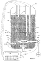
- Figure 1 shows a boiling water heater controlled by a method implementing an embodiment of the invention.
- the tank 100 contains water 102 which has been admitted to the tank at inlet 110 via control valve 108.
- a first level sensor 113 is provided to determine when there is a first predetermined level of water in the tank.
- a second level sensor 112 is provided to indicate to controller 120 when the water has reached the full position. Controller 120 then turns off the valve 108 and stops the water entering the tank 100.
- Additional level sensors can be provided to determine when intermediate levels are reached.
- a third level sensor can be provided to indicate that a minimum level of water is present above the element 104. Thus, if the water level is below this minimum level, the element 104 is inhibited by controller 120 from being turned on.
- a further level sensor can be provided to indicate when the water has fallen below a level at which the controller is programmed to initiate refill. This can prevent the refill starting immediately water is drawn off.
- a continuous level monitor can be provided in the form of a pair of capacitor plates running from the upper level to the bottom of the tank or the minimum level.
- the capacitance varies with the amount of water between the plates.
- the capacitance can be measured by known techniques such as applying a HF signal and calculating the capacitance from the measured parameters and adjusting for temperature effects on the dielectric characteristics of the water.
- the capacitor plates can be formed as concentric cylindrical surfaces with a space between which fills with water to the height of the water in the tank.
- One or more temperature sensors 116, 118 measure the temperature of the water in the tank. Where more than one temperature sensors is provided, they can be located at differing heights within the tank 100. For example, a sensor can be located proximate the minimum water level below which the controller 120 inhibits the element 104. The temperature sensor 116 is located below the fill level. The temperature sensor 118 is located below the predetermined level detected by level detector 113.
- Water can be drawn off via tap 114.
- the controller 120 can include a display 122 and a user interface such as keypad 124. Other interfaces such as touch screen, infrared or wireless interfaces can also be used.
- the controller 120 can be provided with a scrollable function menu which the user can control by one or more function buttons.
- the controller 120 receives input signals from the temperature sensors 116, 118, and from the levels sensors 112, 113. In response to the input conditions meeting operating criteria, the controller controls the inlet valve 108 and the power switch 106.
- Figure 2 schematically illustrates a functional block diagram of a controller adapted for use with the inventive heater.
- a processor 202 and its peripheral elements are interconnected by a bus 204.
- the controller included, for example, a ROM 208 adapted to store programming for the processor 202, an NVRAM 206, a scratch pad memory 218 a clock 230, a user input interface such as keypad interface 224, a display interface 222.
- input interface 210 and output interface 220 are connected to the processor via the bus 204.
- the level sensors and temperature sensors are connected to the input interface 210, and the control outputs for the switch control 226 and the valve control 228 are connected to the output interface 220.
- the input interface and the output interface can be part of a common interface such as a USB interface.
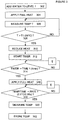
- Figure 3 is a flow diagram of a first mode of operation of the boiling water heater.
- a first step 302 water is added to tank 100 to a predetermined level, such as the level 111 determined by level sensor 113 and the water inlet is then shut off. Full heat is then applied at step 304 via the heating element 104 and the temperature is monitored at step 306 until it reaches a first predetermined temperature threshold T1 (308), which, in this embodiment has been chosen as 88°C. A thermostat can be used to maintain this temperature.
- T1 a first predetermined temperature threshold
- T1 the power supplied by the element 104 is reduced to a level sufficient to maintain the temperature at approximately at T1 at step 310. This can be done by reducing the duty cycle of the heating element 104, ie, by switching the element on and off for periods of time to reduce the average power delivered by the element 104.
- a timing function is initiated at step 312 when the temperature reaches T1 and the temperature is held at T1 for a predetermined period, for example, 4 minutes (314).
- step 316 full heat is again reapplied and the rate of temperature change is monitored at step 318 until it falls to a threshold rate, 0.1C/2.56 sec in this embodiment.
- the rate can be measured for a number of iterations, eg, 8 samples at 2.56 sec intervals at step 318, and when the rate is below the threshold rate for 8 successive samples, the temperature is measured at step 320. This temperature is taken to be the boiling point and is stored in a memory. This can be volatile memory 218 or non-volatile memory 206.
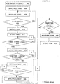
- steps 302 to 320 are repeated as steps 402 to 420.
- Steps 322 can optionally be repeated.
- the temperature is measured at 420.
- step 424 this is held for a time period, in this embodiment 8 minutes.
- Full heat is then applied at 426, and the temperature change rate monitored at 428 until a predetermine rate is reached, again 0.1C/2.56 sec is chosen in this embodiment.
- the temperature is measured at step 430 and stored in memory at step 432. Preferably, this temperature is stored in non-volatile memory 206.
- the double calibration including both steps 302 to 322 and 424 to 432 assist in providing consistent and repeatable calibration temperatures.
- this process can be applied across a range of boiling water heaters, for example, 3 to 40 litre capacities.
- This calibration process can be carried out when the heater has not been previously calibrated.
- the water should boil at greater than 92°C.
- the system can be set to require that the element has been at full power for greater than a further predetermined period, such as 1 minute.
- the timer will run for a further predetermined time period, say 10 minutes, and the temperature then recorded will be taken as the boiling point.
- This time period commences when the temperature exceeds a selected threshold value such as 92°C for mode 1 operation (i.e. 318 & 418) and for mode 2 operation after the 8 minute time period (i.e. 424).
- a calibration reset button can be provided on the controller. This can be used to initiate a calibration process by selecting the calibration item from the menu on the display 122. On initial start up, the unit will calibrate at a low water level, but once commissioned the unit can be re-calibrated anywhere between low level and high level by activating the relevant push buttons.
Landscapes
- Engineering & Computer Science (AREA)
- Physics & Mathematics (AREA)
- Thermal Sciences (AREA)
- Chemical & Material Sciences (AREA)
- Combustion & Propulsion (AREA)
- Mechanical Engineering (AREA)
- General Engineering & Computer Science (AREA)
- Computer Hardware Design (AREA)
- Fluid Mechanics (AREA)
- Food Science & Technology (AREA)
- Cookers (AREA)
- Heat-Pump Type And Storage Water Heaters (AREA)
Description
- This invention relates to water heaters and methods of control thereof.
- The invention is applicable to water heaters which are operated at an upper temperature threshold, such as boiling water heaters for providing hot water for beverages.
- Boiling water heaters are usually used to provide hot water for beverages and are required to provide water at close to boiling point. However, the boiling point for water depends on the atmospheric pressure, which can vary according to factors such as weather conditions and altitude. In addition, minimization of power consumption is now an important factor for equipment suppliers and consumers. Having a continuously boiling heater is wasteful of energy, and generates steam which can also be unacceptable for the user. Thus it is now the practice of boiling water heater suppliers to provide a heater which heats the water to a temperature threshold a degree or two below the boiling point. This necessitates the calibration of the heater to the local boiling temperature. Other refinements, such as the ramping down of the temperature as the water approaches the boiling point have also been adopted to prevent temperature overrun from the thermal inertia of the element.
- According to an embodiment of the invention, there is provided a method of calibrating a water heater, the method including the steps of:
- A. adding water to the tank to a first predetermined water level;
- B. heating the water to a first temperature threshold;
- C. maintaining the temperature at approximately the first temperature threshold for a first period of time;
- D. heating the water until the rate of temperature change is less than a first predetermined rate;
- E. measuring the temperature (T1) when the state of step D is achieved to determine a first iteration temperature.
- F. measuring the time for the water to reach the state of step E, and
- G. comparing the time with a third predetermined time period.
- H. recording the first iteration temperature measured at step E as the boiling point.
- The method can include the steps of:
- I. reducing the power to the element to a level sufficient to maintain the water at the first iteration temperature for a second predetermined period (8 min);
- J. applying full power to the element until the state of step D is achieved;
- K. measuring the temperature attained at step J;
- L. recording the temperature attained measured at step J as the boiling point, wherein steps J, K, and L are carried out instead of or subsequent to, step F.
- The method can include the steps of:
- M. measuring time to achieve step D,
- N. comparing the time measured at step M with a third time period; and, if the time measured at M exceeds the third time period,
- O. measuring the water temperature at the end of the third time period;
- P. recording the water temperature measured at step O as the boiling point.
- The first predetermined water level may be less than the full level.
- The first predetermined water level may be at a predetermined height above the element.
- The invention also provides a controller for implementing the method, and a water heater including such a controller.
- An embodiment or embodiments of the present invention will now be described, by way of example only, with reference to the accompanying drawings, in which:
-
Figure 1 is shows a functional schematic drawing of a boiling water heater embodying the invention; -
Figure 2 is a functional block diagram illustrative of functional elements of a controller adapted for use with the present invention; and -
Figure 3 is a flow diagram of a first mode of operation of the boiling water heater. -
Figure 4 is a flow diagram of both the first and second mode of operation of the boiling water heater. - The following reference numbers are used in the drawings:
FIGURE 1 FIGURE 2 FIGURE 3 100 TANK 200 CONTROLLER 302 ADD WATER 102 WATER 202 PROCESSOR 304 HEAT 104 ELEMENT 204 BUS 306 MEASURE TEMP 106 SWITCH 206 NVRAM 308 COMPARE TEMP 108 VALVE 208 ROM 310 REDUCE HEAT 110 WATER INLET 210 INPUT I/ F 312 START TIMER 112 LEVEL SENSOR 1212 LEVEL SENSOR 314 TIME 113 LEVEL SENSOR 2213 UPPER LEVEL SENSOR 316 FULL HEAT 114 OUTLET 216 TEMP SENSOR 318 TEMP/ TIME 116 TEMP SENSOR 1218 SCRATCH PAD 320 MEASURE TEMP 118 TEMP SENSOR 2220 OUTPUT INTERFACE 322 STORE TEMP 120 CONTROLLER 222 DISPLAY I/ F 122 DISPLAY 224 KEYPAD I/ F 124 KEYPAD 226 SWITCH 228 VALVE 230 CLOCK FIGURE 4 402 ADD WATER 404 HEAT 406 MEASURE TEMP 408 COMPARE TEMP 410 REDUCE HEAT 412 START TIMER 414 TIME 416 FULL HEAT 418 TEMP/ TIME 420 MEASURE TEMP 424 TIME 426 FULL HEAT 428 TEMP/ TIME 430 MEASURE TEMP 432 STORE TEMP - The invention will be described with reference to a boiling water heater.
-
Figure 1 shows a boiling water heater controlled by a method implementing an embodiment of the invention. - As shown in
Figure 1 , thetank 100 containswater 102 which has been admitted to the tank atinlet 110 viacontrol valve 108. Afirst level sensor 113 is provided to determine when there is a first predetermined level of water in the tank. Asecond level sensor 112 is provided to indicate to controller 120 when the water has reached the full position.Controller 120 then turns off thevalve 108 and stops the water entering thetank 100. - Additional level sensors can be provided to determine when intermediate levels are reached. For example, a third level sensor can be provided to indicate that a minimum level of water is present above the
element 104. Thus, if the water level is below this minimum level, theelement 104 is inhibited bycontroller 120 from being turned on. A further level sensor can be provided to indicate when the water has fallen below a level at which the controller is programmed to initiate refill. This can prevent the refill starting immediately water is drawn off. - A continuous level monitor can be provided in the form of a pair of capacitor plates running from the upper level to the bottom of the tank or the minimum level. The capacitance varies with the amount of water between the plates. The capacitance can be measured by known techniques such as applying a HF signal and calculating the capacitance from the measured parameters and adjusting for temperature effects on the dielectric characteristics of the water. The capacitor plates can be formed as concentric cylindrical surfaces with a space between which fills with water to the height of the water in the tank.
- One or
more temperature sensors tank 100. For example, a sensor can be located proximate the minimum water level below which thecontroller 120 inhibits theelement 104. Thetemperature sensor 116 is located below the fill level. Thetemperature sensor 118 is located below the predetermined level detected bylevel detector 113. - Water can be drawn off via
tap 114. - The
controller 120 can include adisplay 122 and a user interface such askeypad 124. Other interfaces such as touch screen, infrared or wireless interfaces can also be used. - The
controller 120 can be provided with a scrollable function menu which the user can control by one or more function buttons. - The
controller 120 receives input signals from thetemperature sensors levels sensors inlet valve 108 and thepower switch 106. -
Figure 2 schematically illustrates a functional block diagram of a controller adapted for use with the inventive heater. - A
processor 202 and its peripheral elements are interconnected by a bus 204. The controller included, for example, aROM 208 adapted to store programming for theprocessor 202, anNVRAM 206, a scratch pad memory 218 aclock 230, a user input interface such askeypad interface 224, adisplay interface 222. Inaddition input interface 210 andoutput interface 220 are connected to the processor via the bus 204. - The level sensors and temperature sensors are connected to the
input interface 210, and the control outputs for theswitch control 226 and thevalve control 228 are connected to theoutput interface 220. - The input interface and the output interface can be part of a common interface such as a USB interface.
-
Figure 3 is a flow diagram of a first mode of operation of the boiling water heater. - In a
first step 302, water is added totank 100 to a predetermined level, such as thelevel 111 determined bylevel sensor 113 and the water inlet is then shut off. Full heat is then applied atstep 304 via theheating element 104 and the temperature is monitored atstep 306 until it reaches a first predetermined temperature threshold T1 (308), which, in this embodiment has been chosen as 88°C. A thermostat can be used to maintain this temperature. When T1 is reached, the power supplied by theelement 104 is reduced to a level sufficient to maintain the temperature at approximately at T1 atstep 310. This can be done by reducing the duty cycle of theheating element 104, ie, by switching the element on and off for periods of time to reduce the average power delivered by theelement 104. - A timing function is initiated at
step 312 when the temperature reaches T1 and the temperature is held at T1 for a predetermined period, for example, 4 minutes (314). - Thereafter, at
step 316, full heat is again reapplied and the rate of temperature change is monitored atstep 318 until it falls to a threshold rate, 0.1C/2.56 sec in this embodiment. - The rate can be measured for a number of iterations, eg, 8 samples at 2.56 sec intervals at
step 318, and when the rate is below the threshold rate for 8 successive samples, the temperature is measured atstep 320. This temperature is taken to be the boiling point and is stored in a memory. This can bevolatile memory 218 ornon-volatile memory 206. - According to a further embodiment of the invention, shown in
Figure 4 ,steps 302 to 320 are repeated assteps 402 to 420.Steps 322 can optionally be repeated. The temperature is measured at 420. Then atstep 424, this is held for a time period, in this embodiment 8 minutes. Full heat is then applied at 426, and the temperature change rate monitored at 428 until a predetermine rate is reached, again 0.1C/2.56 sec is chosen in this embodiment. The temperature is measured atstep 430 and stored in memory atstep 432. Preferably, this temperature is stored innon-volatile memory 206. - The double calibration including both
steps 302 to 322 and 424 to 432 assist in providing consistent and repeatable calibration temperatures. In particular, this process can be applied across a range of boiling water heaters, for example, 3 to 40 litre capacities. - This calibration process can be carried out when the heater has not been previously calibrated.
- Following
step - In the event that boiling is not detected at 318,418 or 428, the timer will run for a further predetermined time period, say 10 minutes, and the temperature then recorded will be taken as the boiling point. This time period commences when the temperature exceeds a selected threshold value such as 92°C for
mode 1 operation (i.e. 318 & 418) and formode 2 operation after the 8 minute time period (i.e. 424). - When the heater has been calibrated, incremental filling from
level 111 to the full level commences as thecontroller 120 opensvalve 108. In this process, water is added until the temperature falls below a chosen value while the heater is at full power. When the water temperature falls to the chosen value, the water inlet is shut off by thecontroller closing valve 108 and is held closed until the temperature rises to a value within an acceptable temperature range suitable for use with hot beverages. This process is repeated until the full level is reached. - A calibration reset button can be provided on the controller. This can be used to initiate a calibration process by selecting the calibration item from the menu on the
display 122. On initial start up, the unit will calibrate at a low water level, but once commissioned the unit can be re-calibrated anywhere between low level and high level by activating the relevant push buttons. - Where ever it is used, the word "comprising" is to be understood in its "open" sense, that is, in the sense of "including", and thus not limited to its "closed" sense, that is the sense of "consisting only of'. A corresponding meaning is to be attributed to the corresponding words "comprise", "comprised" and "comprises" where they appear.
- While particular embodiments of this invention have been described, it will be evident to those skilled in the art that the present invention may be embodied in other specific forms without departing from the essential characteristics thereof. The present embodiments and examples are therefore to be considered in all respects as illustrative and not restrictive, and all modifications within the scope of protection as defined in the claims are therefore intended to be embraced therein.
Claims (8)
- A method of calibrating a water heater, the method including the steps of:A. adding water to the tank to a first predetermined water level (402);B. heating the water to a first temperature threshold (404, 408, 410);C. maintaining the temperature at approximately the first temperature threshold for a first period of time (414);the method being characterized in that these steps are followed byD. heating the water until the rate of temperature change is less than a first predetermined rate (416, 418);E. measuring the temperature (T1) of the water when the state of step D is achieved to determine a first iteration temperature (420);F. measuring the time for the water to reach the state of step E (420), andG. comparing the time with a third predetermined time period (428).
- A method as claimed in claim 1, including the step of:H. recording the first iteration temperature measured at step E as the boiling point.
- A method as claimed in any one of the preceding claims, including the steps of:1. reducing the power to the element to a level sufficient to maintain the water at the first iteration temperature for a second predetermined period (8 min) (424);J. applying full power to the element until the state of step D is achieved (426);K. measuring the temperature attained at step J;L. recording the temperature attained measured at step J as the boiling point, wherein steps J, K, and L are carried out instead of or subsequent to, step F.
- A method as claimed in claim 3, including the steps ofM. measuring time to achieve step J ,N. comparing the time measured at step M with said third time period (428); and, if the time measured at M exceeds the third time period,O. measuring the temperature at the end of the third time period;P. recording the temperature measured at step O as the boiling point.
- A method as claimed in any one of the preceding claims, wherein the first predetermined water level is less than the full level.
- A method as claimed in claim 5, wherein the first predetermined water level is at a predetermined height above the element.
- A controller for a boiling water heater, the controller including a processor programmed to implement the method of any one of claims 1 to 6.
- A boiling water heater including a controller as claimed in claim 7.
Applications Claiming Priority (2)
| Application Number | Priority Date | Filing Date | Title |
|---|---|---|---|
| AU2007901960A AU2007901960A0 (en) | 2007-04-13 | Improvements in Water Heaters | |
| PCT/AU2008/000500 WO2008124865A1 (en) | 2007-04-13 | 2008-04-08 | Improvements in water heaters |
Publications (3)
| Publication Number | Publication Date |
|---|---|
| EP2140206A1 EP2140206A1 (en) | 2010-01-06 |
| EP2140206A4 EP2140206A4 (en) | 2015-05-13 |
| EP2140206B1 true EP2140206B1 (en) | 2017-05-31 |
Family
ID=39863155
Family Applications (1)
| Application Number | Title | Priority Date | Filing Date |
|---|---|---|---|
| EP08747913.5A Not-in-force EP2140206B1 (en) | 2007-04-13 | 2008-04-08 | Improvements in water heaters |
Country Status (5)
| Country | Link |
|---|---|
| EP (1) | EP2140206B1 (en) |
| AU (1) | AU2008238594B2 (en) |
| NZ (1) | NZ579929A (en) |
| WO (1) | WO2008124865A1 (en) |
| ZA (1) | ZA200906713B (en) |
Families Citing this family (4)
| Publication number | Priority date | Publication date | Assignee | Title |
|---|---|---|---|---|
| EP2551605B1 (en) * | 2011-07-29 | 2016-03-30 | STIEBEL ELTRON GmbH & Co. KG | Hot water device and method for operating a hot water device |
| WO2013126945A1 (en) * | 2012-02-27 | 2013-09-06 | Zip Industries (Aust) Pty Ltd | A water heater and a method of operating same |
| AU2014221238B2 (en) * | 2014-05-27 | 2019-01-17 | Supakwik Water Heaters Pty. Ltd. | Water dispensing system |
| CN105919438B (en) * | 2016-05-24 | 2019-03-15 | 平湖科能电器技术有限公司 | A kind of fast electric heating drinking machine |
Family Cites Families (9)
| Publication number | Priority date | Publication date | Assignee | Title |
|---|---|---|---|---|
| JPS58193026A (en) * | 1982-05-04 | 1983-11-10 | Matsushita Electric Ind Co Ltd | Heater with boiling point detector |
| NL8602802A (en) * | 1986-11-05 | 1988-06-01 | Verheijen Bv | DEVICE FOR DELIVERING HOT WATER. |
| AU633042B2 (en) * | 1989-01-26 | 1993-01-21 | Otter Controls Limited | Controls for electrically powered heating elements |
| JP3148914B2 (en) * | 1994-09-28 | 2001-03-26 | 松下電器産業株式会社 | Electric water heater |
| JPH10314030A (en) * | 1997-05-22 | 1998-12-02 | Matsushita Electric Ind Co Ltd | Electric water heater |
| JP4078036B2 (en) * | 2001-02-20 | 2008-04-23 | 東芝キヤリア株式会社 | Heat pump water heater |
| JP3931814B2 (en) * | 2003-01-31 | 2007-06-20 | 株式会社デンソー | Hot water storage water heater |
| US20080257281A1 (en) * | 2004-03-15 | 2008-10-23 | Zip Industries (Aust) Pty Ltd | Water Heater and a Method of Operating Same |
| JP2006200806A (en) * | 2005-01-20 | 2006-08-03 | Matsushita Electric Ind Co Ltd | Water heater |
-
2008
- 2008-04-08 EP EP08747913.5A patent/EP2140206B1/en not_active Not-in-force
- 2008-04-08 WO PCT/AU2008/000500 patent/WO2008124865A1/en not_active Ceased
- 2008-04-08 NZ NZ579929A patent/NZ579929A/en unknown
- 2008-04-08 AU AU2008238594A patent/AU2008238594B2/en active Active
-
2009
- 2009-09-25 ZA ZA200906713A patent/ZA200906713B/en unknown
Also Published As
| Publication number | Publication date |
|---|---|
| WO2008124865A1 (en) | 2008-10-23 |
| EP2140206A4 (en) | 2015-05-13 |
| ZA200906713B (en) | 2010-06-30 |
| AU2008238594A1 (en) | 2008-10-23 |
| NZ579929A (en) | 2012-02-24 |
| EP2140206A1 (en) | 2010-01-06 |
| AU2008238594B2 (en) | 2011-04-28 |
Similar Documents
| Publication | Publication Date | Title |
|---|---|---|
| US10905278B2 (en) | System for precise temperature control of liquids in consumer products | |
| US20240183580A1 (en) | Electronic Control System for Electric Water Heater | |
| AU2008238594B2 (en) | Improvements in water heaters | |
| EP1735569B1 (en) | A water heater and a method of operating same | |
| JPH0252780B2 (en) | ||
| EP2820358B1 (en) | A water heater and a method of operating same | |
| CN100541359C (en) | Fuzzy Control Method of Liquid Heating and Boiling | |
| EP1923764A1 (en) | A method of judging water boiling in electric kettles | |
| GB2463937A (en) | A self-calibrating temperature sensor for a kettle | |
| AU2005222440C1 (en) | A water heater and a method of operating same | |
| HK1022965A (en) | A method for the operation of an electric heating apparatus | |
| JPH0322552B2 (en) | ||
| JPS5840432A (en) | Microwave range | |
| JPH1026416A (en) | Bath burner with hot water feeder | |
| HK1093551B (en) | A water heater and a method of operating same | |
| JPH0531027A (en) | Electric rice boiler | |
| KR980008136A (en) | Electric pressure Rice cooker lid How to prevent water condensation | |
| JPH0468259A (en) | Thermal insulating method for hot water in bath tub | |
| JPS6176845A (en) | Control device for electric water heater | |
| HK1200205B (en) | A water heater and a method of operating same | |
| JPH037114A (en) | Electric water boiler | |
| KR19980073137A (en) | Seasonal judgment method using infrared sensor and temperature control method of menu according to seasonal condition |
Legal Events
| Date | Code | Title | Description |
|---|---|---|---|
| PUAI | Public reference made under article 153(3) epc to a published international application that has entered the european phase |
Free format text: ORIGINAL CODE: 0009012 |
|
| 17P | Request for examination filed |
Effective date: 20091015 |
|
| AK | Designated contracting states |
Kind code of ref document: A1 Designated state(s): AT BE BG CH CY CZ DE DK EE ES FI FR GB GR HR HU IE IS IT LI LT LU LV MC MT NL NO PL PT RO SE SI SK TR |
|
| RIN1 | Information on inventor provided before grant (corrected) |
Inventor name: TROUTE, PATRICK |
|
| DAX | Request for extension of the european patent (deleted) | ||
| RIN1 | Information on inventor provided before grant (corrected) |
Inventor name: ECHTNER, GEORGE Inventor name: TROUTE, PATRICK |
|
| RA4 | Supplementary search report drawn up and despatched (corrected) |
Effective date: 20150414 |
|
| RIC1 | Information provided on ipc code assigned before grant |
Ipc: F24H 1/18 20060101ALI20150408BHEP Ipc: A47J 31/56 20060101ALI20150408BHEP Ipc: F24D 19/10 20060101ALI20150408BHEP Ipc: F24H 1/20 20060101ALI20150408BHEP Ipc: G12B 13/00 20060101ALI20150408BHEP Ipc: F24H 1/08 20060101ALI20150408BHEP Ipc: F24H 9/20 20060101ALI20150408BHEP Ipc: F24D 17/00 20060101AFI20150408BHEP |
|
| GRAP | Despatch of communication of intention to grant a patent |
Free format text: ORIGINAL CODE: EPIDOSNIGR1 |
|
| INTG | Intention to grant announced |
Effective date: 20161103 |
|
| GRAS | Grant fee paid |
Free format text: ORIGINAL CODE: EPIDOSNIGR3 |
|
| GRAA | (expected) grant |
Free format text: ORIGINAL CODE: 0009210 |
|
| AK | Designated contracting states |
Kind code of ref document: B1 Designated state(s): AT BE BG CH CY CZ DE DK EE ES FI FR GB GR HR HU IE IS IT LI LT LU LV MC MT NL NO PL PT RO SE SI SK TR |
|
| REG | Reference to a national code |
Ref country code: CH Ref legal event code: EP Ref country code: GB Ref legal event code: FG4D |
|
| REG | Reference to a national code |
Ref country code: AT Ref legal event code: REF Ref document number: 897855 Country of ref document: AT Kind code of ref document: T Effective date: 20170615 |
|
| REG | Reference to a national code |
Ref country code: IE Ref legal event code: FG4D |
|
| REG | Reference to a national code |
Ref country code: DE Ref legal event code: R096 Ref document number: 602008050481 Country of ref document: DE |
|
| REG | Reference to a national code |
Ref country code: NL Ref legal event code: MP Effective date: 20170531 |
|
| REG | Reference to a national code |
Ref country code: LT Ref legal event code: MG4D |
|
| REG | Reference to a national code |
Ref country code: AT Ref legal event code: MK05 Ref document number: 897855 Country of ref document: AT Kind code of ref document: T Effective date: 20170531 |
|
| PG25 | Lapsed in a contracting state [announced via postgrant information from national office to epo] |
Ref country code: LT Free format text: LAPSE BECAUSE OF FAILURE TO SUBMIT A TRANSLATION OF THE DESCRIPTION OR TO PAY THE FEE WITHIN THE PRESCRIBED TIME-LIMIT Effective date: 20170531 Ref country code: AT Free format text: LAPSE BECAUSE OF FAILURE TO SUBMIT A TRANSLATION OF THE DESCRIPTION OR TO PAY THE FEE WITHIN THE PRESCRIBED TIME-LIMIT Effective date: 20170531 Ref country code: ES Free format text: LAPSE BECAUSE OF FAILURE TO SUBMIT A TRANSLATION OF THE DESCRIPTION OR TO PAY THE FEE WITHIN THE PRESCRIBED TIME-LIMIT Effective date: 20170531 Ref country code: NO Free format text: LAPSE BECAUSE OF FAILURE TO SUBMIT A TRANSLATION OF THE DESCRIPTION OR TO PAY THE FEE WITHIN THE PRESCRIBED TIME-LIMIT Effective date: 20170831 Ref country code: FI Free format text: LAPSE BECAUSE OF FAILURE TO SUBMIT A TRANSLATION OF THE DESCRIPTION OR TO PAY THE FEE WITHIN THE PRESCRIBED TIME-LIMIT Effective date: 20170531 Ref country code: GR Free format text: LAPSE BECAUSE OF FAILURE TO SUBMIT A TRANSLATION OF THE DESCRIPTION OR TO PAY THE FEE WITHIN THE PRESCRIBED TIME-LIMIT Effective date: 20170901 Ref country code: HR Free format text: LAPSE BECAUSE OF FAILURE TO SUBMIT A TRANSLATION OF THE DESCRIPTION OR TO PAY THE FEE WITHIN THE PRESCRIBED TIME-LIMIT Effective date: 20170531 |
|
| PG25 | Lapsed in a contracting state [announced via postgrant information from national office to epo] |
Ref country code: BG Free format text: LAPSE BECAUSE OF FAILURE TO SUBMIT A TRANSLATION OF THE DESCRIPTION OR TO PAY THE FEE WITHIN THE PRESCRIBED TIME-LIMIT Effective date: 20170831 Ref country code: LV Free format text: LAPSE BECAUSE OF FAILURE TO SUBMIT A TRANSLATION OF THE DESCRIPTION OR TO PAY THE FEE WITHIN THE PRESCRIBED TIME-LIMIT Effective date: 20170531 Ref country code: IS Free format text: LAPSE BECAUSE OF FAILURE TO SUBMIT A TRANSLATION OF THE DESCRIPTION OR TO PAY THE FEE WITHIN THE PRESCRIBED TIME-LIMIT Effective date: 20170930 Ref country code: NL Free format text: LAPSE BECAUSE OF FAILURE TO SUBMIT A TRANSLATION OF THE DESCRIPTION OR TO PAY THE FEE WITHIN THE PRESCRIBED TIME-LIMIT Effective date: 20170531 Ref country code: SE Free format text: LAPSE BECAUSE OF FAILURE TO SUBMIT A TRANSLATION OF THE DESCRIPTION OR TO PAY THE FEE WITHIN THE PRESCRIBED TIME-LIMIT Effective date: 20170531 |
|
| PG25 | Lapsed in a contracting state [announced via postgrant information from national office to epo] |
Ref country code: SK Free format text: LAPSE BECAUSE OF FAILURE TO SUBMIT A TRANSLATION OF THE DESCRIPTION OR TO PAY THE FEE WITHIN THE PRESCRIBED TIME-LIMIT Effective date: 20170531 Ref country code: CZ Free format text: LAPSE BECAUSE OF FAILURE TO SUBMIT A TRANSLATION OF THE DESCRIPTION OR TO PAY THE FEE WITHIN THE PRESCRIBED TIME-LIMIT Effective date: 20170531 Ref country code: RO Free format text: LAPSE BECAUSE OF FAILURE TO SUBMIT A TRANSLATION OF THE DESCRIPTION OR TO PAY THE FEE WITHIN THE PRESCRIBED TIME-LIMIT Effective date: 20170531 Ref country code: DK Free format text: LAPSE BECAUSE OF FAILURE TO SUBMIT A TRANSLATION OF THE DESCRIPTION OR TO PAY THE FEE WITHIN THE PRESCRIBED TIME-LIMIT Effective date: 20170531 Ref country code: EE Free format text: LAPSE BECAUSE OF FAILURE TO SUBMIT A TRANSLATION OF THE DESCRIPTION OR TO PAY THE FEE WITHIN THE PRESCRIBED TIME-LIMIT Effective date: 20170531 |
|
| PG25 | Lapsed in a contracting state [announced via postgrant information from national office to epo] |
Ref country code: IT Free format text: LAPSE BECAUSE OF FAILURE TO SUBMIT A TRANSLATION OF THE DESCRIPTION OR TO PAY THE FEE WITHIN THE PRESCRIBED TIME-LIMIT Effective date: 20170531 Ref country code: PL Free format text: LAPSE BECAUSE OF FAILURE TO SUBMIT A TRANSLATION OF THE DESCRIPTION OR TO PAY THE FEE WITHIN THE PRESCRIBED TIME-LIMIT Effective date: 20170531 |
|
| REG | Reference to a national code |
Ref country code: DE Ref legal event code: R097 Ref document number: 602008050481 Country of ref document: DE |
|
| PLBE | No opposition filed within time limit |
Free format text: ORIGINAL CODE: 0009261 |
|
| STAA | Information on the status of an ep patent application or granted ep patent |
Free format text: STATUS: NO OPPOSITION FILED WITHIN TIME LIMIT |
|
| 26N | No opposition filed |
Effective date: 20180301 |
|
| PG25 | Lapsed in a contracting state [announced via postgrant information from national office to epo] |
Ref country code: SI Free format text: LAPSE BECAUSE OF FAILURE TO SUBMIT A TRANSLATION OF THE DESCRIPTION OR TO PAY THE FEE WITHIN THE PRESCRIBED TIME-LIMIT Effective date: 20170531 |
|
| REG | Reference to a national code |
Ref country code: DE Ref legal event code: R119 Ref document number: 602008050481 Country of ref document: DE |
|
| PG25 | Lapsed in a contracting state [announced via postgrant information from national office to epo] |
Ref country code: MC Free format text: LAPSE BECAUSE OF FAILURE TO SUBMIT A TRANSLATION OF THE DESCRIPTION OR TO PAY THE FEE WITHIN THE PRESCRIBED TIME-LIMIT Effective date: 20170531 |
|
| REG | Reference to a national code |
Ref country code: CH Ref legal event code: PL |
|
| REG | Reference to a national code |
Ref country code: BE Ref legal event code: MM Effective date: 20180430 |
|
| PG25 | Lapsed in a contracting state [announced via postgrant information from national office to epo] |
Ref country code: LU Free format text: LAPSE BECAUSE OF NON-PAYMENT OF DUE FEES Effective date: 20180408 Ref country code: DE Free format text: LAPSE BECAUSE OF NON-PAYMENT OF DUE FEES Effective date: 20181101 |
|
| PG25 | Lapsed in a contracting state [announced via postgrant information from national office to epo] |
Ref country code: CH Free format text: LAPSE BECAUSE OF NON-PAYMENT OF DUE FEES Effective date: 20180430 Ref country code: LI Free format text: LAPSE BECAUSE OF NON-PAYMENT OF DUE FEES Effective date: 20180430 Ref country code: BE Free format text: LAPSE BECAUSE OF NON-PAYMENT OF DUE FEES Effective date: 20180430 |
|
| PG25 | Lapsed in a contracting state [announced via postgrant information from national office to epo] |
Ref country code: FR Free format text: LAPSE BECAUSE OF NON-PAYMENT OF DUE FEES Effective date: 20180430 |
|
| PG25 | Lapsed in a contracting state [announced via postgrant information from national office to epo] |
Ref country code: MT Free format text: LAPSE BECAUSE OF NON-PAYMENT OF DUE FEES Effective date: 20180408 |
|
| PG25 | Lapsed in a contracting state [announced via postgrant information from national office to epo] |
Ref country code: TR Free format text: LAPSE BECAUSE OF FAILURE TO SUBMIT A TRANSLATION OF THE DESCRIPTION OR TO PAY THE FEE WITHIN THE PRESCRIBED TIME-LIMIT Effective date: 20170531 |
|
| PG25 | Lapsed in a contracting state [announced via postgrant information from national office to epo] |
Ref country code: HU Free format text: LAPSE BECAUSE OF FAILURE TO SUBMIT A TRANSLATION OF THE DESCRIPTION OR TO PAY THE FEE WITHIN THE PRESCRIBED TIME-LIMIT; INVALID AB INITIO Effective date: 20080408 Ref country code: PT Free format text: LAPSE BECAUSE OF FAILURE TO SUBMIT A TRANSLATION OF THE DESCRIPTION OR TO PAY THE FEE WITHIN THE PRESCRIBED TIME-LIMIT Effective date: 20170531 |
|
| PG25 | Lapsed in a contracting state [announced via postgrant information from national office to epo] |
Ref country code: CY Free format text: LAPSE BECAUSE OF FAILURE TO SUBMIT A TRANSLATION OF THE DESCRIPTION OR TO PAY THE FEE WITHIN THE PRESCRIBED TIME-LIMIT Effective date: 20170531 |
|
| PGFP | Annual fee paid to national office [announced via postgrant information from national office to epo] |
Ref country code: IE Payment date: 20200420 Year of fee payment: 13 |
|
| PGFP | Annual fee paid to national office [announced via postgrant information from national office to epo] |
Ref country code: GB Payment date: 20200427 Year of fee payment: 13 |
|
| GBPC | Gb: european patent ceased through non-payment of renewal fee |
Effective date: 20210408 |
|
| PG25 | Lapsed in a contracting state [announced via postgrant information from national office to epo] |
Ref country code: GB Free format text: LAPSE BECAUSE OF NON-PAYMENT OF DUE FEES Effective date: 20210408 |
|
| PG25 | Lapsed in a contracting state [announced via postgrant information from national office to epo] |
Ref country code: IE Free format text: LAPSE BECAUSE OF NON-PAYMENT OF DUE FEES Effective date: 20210408 |