EP2139625B1 - Die holder for fabricating press and method of using such a die holder - Google Patents
Die holder for fabricating press and method of using such a die holder Download PDFInfo
- Publication number
- EP2139625B1 EP2139625B1 EP20080730267 EP08730267A EP2139625B1 EP 2139625 B1 EP2139625 B1 EP 2139625B1 EP 20080730267 EP20080730267 EP 20080730267 EP 08730267 A EP08730267 A EP 08730267A EP 2139625 B1 EP2139625 B1 EP 2139625B1
- Authority
- EP
- European Patent Office
- Prior art keywords
- die holder
- die
- clamp
- configuration
- actuator
- Prior art date
- Legal status (The legal status is an assumption and is not a legal conclusion. Google has not performed a legal analysis and makes no representation as to the accuracy of the status listed.)
- Not-in-force
Links
- 238000000034 method Methods 0.000 title claims description 17
- 230000033001 locomotion Effects 0.000 claims description 11
- 230000004044 response Effects 0.000 claims description 9
- 230000008569 process Effects 0.000 claims description 7
- 230000006835 compression Effects 0.000 claims description 4
- 238000007906 compression Methods 0.000 claims description 4
- 230000007246 mechanism Effects 0.000 description 9
- 239000002184 metal Substances 0.000 description 8
- 238000004519 manufacturing process Methods 0.000 description 7
- 229910000639 Spring steel Inorganic materials 0.000 description 6
- 238000003825 pressing Methods 0.000 description 4
- 229910001315 Tool steel Inorganic materials 0.000 description 3
- 230000009471 action Effects 0.000 description 3
- 239000000463 material Substances 0.000 description 3
- 230000003466 anti-cipated effect Effects 0.000 description 2
- 230000007423 decrease Effects 0.000 description 2
- 230000000694 effects Effects 0.000 description 2
- 238000009760 electrical discharge machining Methods 0.000 description 2
- 238000001746 injection moulding Methods 0.000 description 2
- 229910052755 nonmetal Inorganic materials 0.000 description 2
- 241000237858 Gastropoda Species 0.000 description 1
- 230000006978 adaptation Effects 0.000 description 1
- 238000005266 casting Methods 0.000 description 1
- 230000008859 change Effects 0.000 description 1
- 230000005484 gravity Effects 0.000 description 1
- 230000006698 induction Effects 0.000 description 1
- 238000005461 lubrication Methods 0.000 description 1
- 230000005291 magnetic effect Effects 0.000 description 1
- 238000003801 milling Methods 0.000 description 1
- 230000004048 modification Effects 0.000 description 1
- 238000012986 modification Methods 0.000 description 1
- 238000002360 preparation method Methods 0.000 description 1
- 238000004080 punching Methods 0.000 description 1
Images

















Classifications
-
- B—PERFORMING OPERATIONS; TRANSPORTING
- B21—MECHANICAL METAL-WORKING WITHOUT ESSENTIALLY REMOVING MATERIAL; PUNCHING METAL
- B21D—WORKING OR PROCESSING OF SHEET METAL OR METAL TUBES, RODS OR PROFILES WITHOUT ESSENTIALLY REMOVING MATERIAL; PUNCHING METAL
- B21D37/00—Tools as parts of machines covered by this subclass
- B21D37/04—Movable or exchangeable mountings for tools
-
- B—PERFORMING OPERATIONS; TRANSPORTING
- B21—MECHANICAL METAL-WORKING WITHOUT ESSENTIALLY REMOVING MATERIAL; PUNCHING METAL
- B21D—WORKING OR PROCESSING OF SHEET METAL OR METAL TUBES, RODS OR PROFILES WITHOUT ESSENTIALLY REMOVING MATERIAL; PUNCHING METAL
- B21D37/00—Tools as parts of machines covered by this subclass
- B21D37/14—Particular arrangements for handling and holding in place complete dies
-
- Y—GENERAL TAGGING OF NEW TECHNOLOGICAL DEVELOPMENTS; GENERAL TAGGING OF CROSS-SECTIONAL TECHNOLOGIES SPANNING OVER SEVERAL SECTIONS OF THE IPC; TECHNICAL SUBJECTS COVERED BY FORMER USPC CROSS-REFERENCE ART COLLECTIONS [XRACs] AND DIGESTS
- Y10—TECHNICAL SUBJECTS COVERED BY FORMER USPC
- Y10T—TECHNICAL SUBJECTS COVERED BY FORMER US CLASSIFICATION
- Y10T29/00—Metal working
- Y10T29/51—Plural diverse manufacturing apparatus including means for metal shaping or assembling
- Y10T29/5168—Multiple-tool holder
-
- Y—GENERAL TAGGING OF NEW TECHNOLOGICAL DEVELOPMENTS; GENERAL TAGGING OF CROSS-SECTIONAL TECHNOLOGIES SPANNING OVER SEVERAL SECTIONS OF THE IPC; TECHNICAL SUBJECTS COVERED BY FORMER USPC CROSS-REFERENCE ART COLLECTIONS [XRACs] AND DIGESTS
- Y10—TECHNICAL SUBJECTS COVERED BY FORMER USPC
- Y10T—TECHNICAL SUBJECTS COVERED BY FORMER US CLASSIFICATION
- Y10T483/00—Tool changing
- Y10T483/17—Tool changing including machine tool or component
- Y10T483/1733—Rotary spindle machine tool [e.g., milling machine, boring, machine, grinding machine, etc.]
- Y10T483/1736—Tool having specific mounting or work treating feature
-
- Y—GENERAL TAGGING OF NEW TECHNOLOGICAL DEVELOPMENTS; GENERAL TAGGING OF CROSS-SECTIONAL TECHNOLOGIES SPANNING OVER SEVERAL SECTIONS OF THE IPC; TECHNICAL SUBJECTS COVERED BY FORMER USPC CROSS-REFERENCE ART COLLECTIONS [XRACs] AND DIGESTS
- Y10—TECHNICAL SUBJECTS COVERED BY FORMER USPC
- Y10T—TECHNICAL SUBJECTS COVERED BY FORMER US CLASSIFICATION
- Y10T83/00—Cutting
- Y10T83/869—Means to drive or to guide tool
- Y10T83/8727—Plural tools selectively engageable with single drive
- Y10T83/8732—Turret of tools
-
- Y—GENERAL TAGGING OF NEW TECHNOLOGICAL DEVELOPMENTS; GENERAL TAGGING OF CROSS-SECTIONAL TECHNOLOGIES SPANNING OVER SEVERAL SECTIONS OF THE IPC; TECHNICAL SUBJECTS COVERED BY FORMER USPC CROSS-REFERENCE ART COLLECTIONS [XRACs] AND DIGESTS
- Y10—TECHNICAL SUBJECTS COVERED BY FORMER USPC
- Y10T—TECHNICAL SUBJECTS COVERED BY FORMER US CLASSIFICATION
- Y10T83/00—Cutting
- Y10T83/869—Means to drive or to guide tool
- Y10T83/8748—Tool displaceable to inactive position [e.g., for work loading]
-
- Y—GENERAL TAGGING OF NEW TECHNOLOGICAL DEVELOPMENTS; GENERAL TAGGING OF CROSS-SECTIONAL TECHNOLOGIES SPANNING OVER SEVERAL SECTIONS OF THE IPC; TECHNICAL SUBJECTS COVERED BY FORMER USPC CROSS-REFERENCE ART COLLECTIONS [XRACs] AND DIGESTS
- Y10—TECHNICAL SUBJECTS COVERED BY FORMER USPC
- Y10T—TECHNICAL SUBJECTS COVERED BY FORMER US CLASSIFICATION
- Y10T83/00—Cutting
- Y10T83/929—Tool or tool with support
- Y10T83/9457—Joint or connection
- Y10T83/9488—Adjustable
Definitions
- the present invention is in the field of die holders for machine tools. More particularly, this invention relates to die holders for metal-fabricating presses.
- each press includes an upper table and a lower table, and at least one die holder adapted for holding a die securely between the upper and lower tables.
- the die holder is adapted to tightly hold the die with a plurality of set screws.
- the set screws must be loosened before the old die can be removed.
- the new die can be loaded into the die holder (e.g., after moving the new die into the space between the upper and lower tables).
- the upper and lower tables of many presses are relatively close together.
- replacing dies can be a difficult and time consuming process.
- the die can be hard to remove from the die holder due to stiction. Stiction occurs when the die becomes stubbornly stuck in the die holder (e.g., due to a close fit between the die and the die holder, and any lubrication present). Stiction causes additional difficulty because the die must be forced from the die holder.
- WO 99/01240 discloses a press brake tool holder having a horizontally elongated clamp to capture the upwardly extending shank of a brake press tool.
- EP 1447154 discloses a punch press employing cartridges which hold tools. Cartridge holding means are supported by a punch frame and have cartridge clamps.
- the invention provides a die holder for a fabricating press.
- the die holder defines an interior recess configured to receive a die.
- the die holder includes a clamp portion and a wall portion.
- the clamp and wall portions are adapted to be positioned in an open configuration or a closed configuration.
- the clamp and wall portions together surround the interior recess when in the closed configuration.
- the die holder can be adjusted from a clamped configuration to an unclamped configuration by performing an unclamping operation. When the die is received in the interior recess and the die holder is in the clamped configuration, the die is clamped securely by the die holder.
- the die holder according to the invention is provided with a single-motion actuator that allows the unclamping operation to be performed in response to a single motion of the actuator.
- the die holder preferably is provided with a tool-free actuator that allows both the clamping and unclamping operations to be tool-free operations.
- the invention provides a die holder for a fabricating press.
- the die holder defines an interior recess configured to receive a die.
- the die holder includes a clamp portion and a wall portion.
- the die holder preferably is adapted to be adjusted from an unclamped, open configuration to a closed, clamped configuration by performing a single step that comprises pushing together the clamp and wall portions.
- the invention provides a method of using a die holder.
- the die holder defines an interior recess in which a die is provided.
- the die holder includes a clamp portion and a wall portion.
- the method comprises adjusting the die holder from an unclamped, open configuration to a closed, clamped configuration by performing a single step that comprises pushing together the clamp and wall portions.
- the invention provides a die holder.
- the die holder defines an interior recess configured to receive a die.
- the die holder includes a clamp portion and a wall portion.
- the clamp portion is adapted to embrace the die such that when the clamp portion is moved away from the wall portion the die moves together with the clamp portion away from the wall portion.
- the interior recess has a generally circular configuration
- the clamp portion has a concave interior surface
- the wall portion has a concave interior surface
- these interior surfaces are adapted to engage the die when the die holder is clamped securely on the die.
- the die holder has an open configuration that involves a side of the die holder being open.
- Such die holders are useful, for example, for mounting and dismounting dies in a confined space, such as between the upper and lower tables of a press.
- Such die holders can be configured to allow a die to be easily inserted in, or removed from, the die holder from the perimeter of the press. This may avoid the need of having to lift a die upwardly during removal from the die holder, which may be difficult due to the limited space between the tables of the press.
- the die holder can be adjusted from an unclamped configuration to a clamped configuration by performing a clamping operation, and the die holder can be adjusted from the clamped configuration to the unclamped configuration by performing an unclamping operation.
- the die holder is provided with a single-motion actuator, such that the die holder is adapted to clamp in response to a single motion of the actuator.
- the die when the clamp and wall portions are positioned in the open configuration, the die can be mounted in the die holder by moving the die sideways through an open side of the die holder, after which the clamp and wall portions can be positioned in the closed configuration and then the clamping operation can be performed to securely clamp the die holder on the die.
- Some embodiments of the invention provide a die holder for a fabricating press, such as a metal-fabricating press.
- the press has an upper table and a lower table.
- a gap between the upper and lower tables is adapted to receive sheet metal or another sheet-like workpiece.
- the upper table may be omitted.
- the lower table preferably is adapted to have mounted thereon at least one die holder (a wall portion 140 of the die holder may be mounted fixedly on the table, and a clamp portion 130 of the die holder may, in some cases, be adapted for being removably attached to the wall portion).
- the lower table commonly has a horizontal surface on which the die holder can be mounted and/or defining a mount opening in which the die holder can be mounted.
- the mount opening in such a press can optionally have a generally circular configuration. In other cases, the mount opening is adapted to receive a polygonal (e.g., generally square) die holder.
- fabricating press 10 is a turret press, although the fabricating press 10 can be a single-station press or any other fabricating press.
- the fabricating press 10 can include any machine useful for the fabrication of sheet-like workpieces, such as sheet metal or other metal parts.
- the fabrication process itself can include any work step, such as punching holes, creating bends, various forms, etc.
- the fabricating press 10 includes (e.g., is) a turret press 20.
- the turret press 20 can include an upper table (e.g., an upper turret) 30 and a lower table (e.g., a lower turret) 40.
- the upper table 30 and lower table 40 can be separated by a turret gap 50 adapted to receive sheet-like workpieces.
- the turret press 20 can include a plurality of stations (reference is made to Figure 31 ), at least one of which is adapted to receive a die holder 70.
- the die holder 70 is adapted for being removably mounted in an opening 80 defined by a table of the fabricating press 10.
- the embodiment shown in Figure 1 has such openings in the lower table 40, but they are not visible because die holders 70 have been mounted therein).
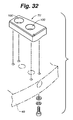
- the die holder is not potted in an opening defined by the lower table, but is bolted or otherwise anchored removably to the table (such as in the same general manner shown in Figure 32 ).
- a wall portion 140 of the die holder 70 can optionally be mounted in a stationary position on the table.
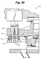
- Metal sheets and/or other workpieces can be placed between the upper and lower turrets, and a punch or other tool mounted on the upper turret (see Figure 30 ) may be caused to act against the workpiece, forcing the workpiece against the die for fabrication.
- the lower and upper tables may be adapted to rotate together to allow any desired tool set to be moved into position to act on the workpiece. In such presses, the dies are changed periodically to accommodate different fabrication operations, and to replace worn dies.
- the die can be moved into the gap and mounted in the die holder.
- the die can be moved into the die holder through an open side of the die holder.
- the open side (which preferably can be closed once the die is mounted on the die holder) may optionally be bounded underneath by an opening base OB of the die holder.
- the opening base OB when provided, desirably has a smaller height than the wall portion 140 of the die holder.
- the opening base OB forms part of the die holder's shelf 110 and defines a portion of the support surface 120 that is adapted to support the bottom of a die.
- the clamp portion 130 of the die holder is in a closed configuration, the clamp portion preferably is carried against (e.g., positioned on top of) at least part of the opening base OB.
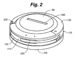
- Figure 2 One exemplary embodiment of a die 90 mounted in a die holder 70 is shown in Figure 2 .
- the clamping operation results in the die holder clamping a single die, although other embodiments involve the clamping operation causing the die holder to simultaneously clamp on at least two dies.
- Figures 39 and 40 depict a multiple-track die holder embodiment wherein the clamping operation causes the die holder to simultaneously clamp on two dies.
- the die holder is used on a single-station fabricating press.
- the press typically does not involve turrets, although the press may still have upper and lower tables (or at least a lower table), as is well known in the present art.
- the die holder 70 can include any apparatus useful for holding a die 90.
- the die holder 70 has an interior recess 100.
- the interior recess 100 may have a generally circular configuration (and/or it may be adapted to receive a die having a generally circular configuration). This, however, is not the case in all embodiments.
- other embodiments involve a polygonal die 90 and a polygonal interior recess 100.
- Polygonal dies of the Salvagnini style are known, and the present die holder can be configured to accommodate such dies.
- Figures 37 and 38 depict one embodiment of a die holder 70 adapted to retain a polygonal (e.g., generally square) die. Embodiments like that of Figures 37 and 38 are described below in more detail.
- the die holder preferably has a shelf 110 adapted to support a bottom (e.g., a planar base) of a die 90.
- the shelf for example, can have (e.g., can define) a support surface 120 on which the bottom of a die is adapted to rest (e.g., when the die is operably mounted in the die holder).
- the die holder has a shoulder 150 defining at least part of the die holder's interior side surface 160, which optionally extends at least generally (e.g., substantially) orthogonally from the shelf 110. The shoulder 150 can bound the interior recess 100.
- the die holder's interior side surface 160 (at least part of which preferably is defined by the shoulder 150) can optionally entirely surround the interior recess 100.
- the die holder 70 can have a central opening 170 (optionally one through which slugs of workpiece material can drop during certain metal fabrication operations), and the shelf 110 can encompass (e.g., can optionally entirely surround) the central opening 170.
- the die holder has an opening base OB one side of which bounds the central opening 170 and another side of which defines an outer perimeter of the die holder.
- the die holder 70 includes a clamp portion 130 and a wall portion 140.
- the clamp portion 130 can optionally comprise (e.g., can be) a concave clamp portion (i.e., it can optionally have a concave interior surface).
- the clamp portion for example, can have a generally C-shaped configuration as shown in many of the drawings.
- the wall portion 140 can optionally comprise (e.g., can be) a concave wall portion.
- the clamp portion 130 and wall portion 140 cooperate to allow the die holder 70 to have a closed configuration, embodiments of which are shown in Figures 1 , 2 , 5 , 8 , 9 , 12 , 13 , 17 , 20 , 21 , 33 , 36 , 38 , 40 , 43 , and 44 , and an open configuration, embodiments of which are shown in Figures 3 , 4 , 6 , 7 , 10 , 11 , 14-16 , 22 , 23 , 34 , 37 , 39 , and 41 .
- the clamp 130 and wall 140 portions together surround the interior recess 100 (optionally entirely surrounding the interior recess, substantially entirely surrounding the interior recess, or surrounding the interior recess to such an extent that a die cannot be mounted in the die holder by simply sliding the die sideways through any side opening).
- the die holder 70 preferably is configured to allow a die 90 to be placed in the die holder 70 or removed from the die holder 70.
- the die holder 70 has a generally annular configuration (and/or at least has a generally circular interior side surface 160 surrounding the interior recess 100).
- the die holder has configurations like those shown in Figures 18 , 19 , or 37-40 . Other die holder configurations can also be provided with the features of any embodiment described in the present disclosure.
- a concave clamp portion 130 has a concave interior surface 180
- a concave wall portion 140 has a concave interior surface 190.
- Those interior surfaces are adapted to surround, abut, and/or engage a die 90 when the die is mounted in the die holder 70 and the die holder is in the closed configuration.
- a concave interior surface 180 of the clamp portion 130 bounds at least 30 degrees, at least 35 degrees, or at least 40 degrees of the interior recess 100 when the clamp and wall portions are in the closed configuration.
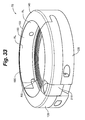
- Figures 33-36 and 41-44 exemplify embodiments wherein the die holder 70 has a clamp portion 130 (optionally defining a concave interior surface 180) that encompasses more than 180 degrees of the interior recess 100.
- a clamp portion 130 can be sized to press fit on, or otherwise embrace, a die such that the clamp portion retains the die when the clamp portion is pulled off (e.g., moved sideways apart from) the wall portion 140.
- the clamp portion when the clamp portion is pulled apart from the wall portion (at such time as a die is mounted in the die holder), the clamp portion holds the die (e.g., holds an exterior sidewall of the die) such that the die and the clamp portion move together away from the die holder's wall portion.
- the present invention covers any die holder that has this functionality, regardless of the details on how the die holder is able to embrace the die.
- the die holder 70 also has a clamped configuration, embodiments of which are shown in Figures 1 , 2 , 5 , 8 , 9 , 12 , 13 , 20 , 21 , 33 , 36 , 38 , 40 , and 43 , and an unclamped configuration, embodiments of which are shown in Figures 3 , 4 , 6 , 7 , 10 , 11 , 14-16 , 22 , 23 , 34 , 37 , 39 , and 41 (also in the open configuration) and in Figures 17 and 44 (also in the closed configuration).
- the clamped configuration is useful for securely clamping a die 90 in the die holder 70.
- the unclamped configuration is useful for allowing the die holder 70 to be reversibly placed in either the open configuration or the closed configuration.
- the die holder can be adjusted from an unclamped configuration to a clamped configuration by performing a clamping operation, and the die holder 70 can be adjusted from the clamped configuration to the unclamped configuration by performing an unclamping operation.
- the die holder 70 includes at least one spring component.
- the spring component is adapted to generate at least part of the clamping force the die holder places on the die.
- the spring component comprises at least one compression spring CSP, optionally provided on the clamp portion 130.
- Figures 41-44 These figures exemplify embodiments wherein the die holder includes at least one engagement body (e.g., at least one axially-moveable locking pin) that is moveable between locked and unlocked positions.
- the engagement body preferably is in the locked position when the die holder is in a clamped position, and the engagement body preferably is in an unlocked position when the die holder is in an unclamped position.
- the (or each) engagement body is resiliently biased (e.g., by a compression spring or other spring component), optionally toward the locked position.
- the (or each) engagement body may be extendable and retractable, and may be resiliently biased toward an extended position.
- FIGS 41-44 there are two engagement bodies (it may be desirable to have a plurality of engagement bodies).
- the engagement bodies shown in Figures 41-44 comprise locking pins adapted to move axially, e.g., between extended and retracted positions (such as between locked and unlocked positions).
- the illustrated locking pins are adapted to move along a vertical axis, i.e., if the die holder is mounted on a horizontal plane. This, however, is not required.
- at least one locking pin or other engagement member is adapted to move along an axis that is oblique to vertical.
- the die holder includes a spring component having a body comprising (e.g., formed of) spring steel.
- a spring steel body (optionally having an arcuate shape) can form at least part of the die holder's clamp portion 130.
- the die holder 70 can apply a clamping force on a die 90 (when the die is in the die holder's interior recess 100) and the optional spring steel body may generate at least part of the clamping force.
- a clamping operation when the clamp and wall portions are in the closed configuration, a clamping operation preferably can be performed so as to decrease a dimension, such as a diameter, of the interior recess (more generally, this can optionally be the case for various embodiments described in this disclosure).
- the die holder includes an actuator 210.
- the actuator is adapted to be moved (e.g., manually, or in some cases robotically or otherwise using hydraulics, pneumatics, electronics, magnetics, or the like) in such a way as to move the die holder between clamped and unclamped configurations.
- the actuator is adapted to be moved in one manner (e.g., in one direction) so as to adjust the die holder from an unclamped position to a clamped position, and the actuator can be moved in a different manner (e.g., in a different direction) so as to adjust the die holder from a clamped position to an unclamped position. This, however, is not the case for all embodiments.
- the die holder is provided with an actuator 210 comprising a body that moves relative to the clamp portion 130 and/or wall portion 140 during clamping and/or unclamping operations.
- This moveable body can optionally be a pivotable body that moves pivotally (e.g., about at least one hinge) during the clamping and/or unclamping operations.
- the pivotable body for example, can be a handle or a latch.
- Figures 33-36 and 41-44 depict exemplary embodiments involving a latch.
- the actuator 210 is a tool-free actuator that allows the unclamping operation, the clamping operation, or both to be tool-free operations (or at least operations that do not involve rotating a set screw or any other threaded fastener).
- the clamping and/or unclamping operations may be performed without a wrench or screw driver.
- Components of the die holder itself, even if removable (e.g., a removable handle actuator), are not considered tools for purposes of the present disclosure.
- some embodiments provide a die holder (which can optionally be a tool-free die holder) that can be clamped and unclamped, and/or adjusted between open and closed configurations, without requiring any assembly or disassembly of the die holder.
- a die holder which can optionally be a tool-free die holder
- These embodiments may involve the die holder having a clamp portion that is pivotally (e.g., hingedly) connected to the die holder's wall portion.
- the actuator 210 is a single-motion actuator that allows the die holder 70 to be unclamped in response to a single motion of the actuator. (In some of these embodiments, the unclamping operation is also a tool-free operation.) Additionally or alternatively, the actuator 210 can be one that allows the die holder to be clamped in response to a single motion of the actuator 210. In some embodiments of this nature, the die holder must be partially assembled (e.g., the clamp portion may need to be joined to the wall portion, and/or a removable handle may need to be joined to the die holder) before the single-motion clamping can be performed.
- the actual clamping in such embodiments preferably occurs in response to a single motion of a single-motion actuator (the same may be true of the actual unclamping).
- Exemplary single motions can be pivoting, pressing, sliding, squeezing, or rotating the actuator 210.
- the die holder 70 is provided with an actuator 210 comprising a body (e.g., a handle) that is moved in one direction (once or repeatedly) during the clamping operation and in another direction (optionally an opposite direction) during the unclamping operation.
- a body e.g., a handle
- the handle or other body can optionally be moveable in a plane that is at least generally parallel (or at least substantially parallel) to the shelfs support surface (such that the handle or other body moves in that plane to cause the clamping and unclamping operations).
- the handle or other body may be adapted to move horizontally.
- the gap 50 can be a generally horizontal gap
- the single-motion actuator 210 can optionally comprise a handle that is moved at least generally horizontally during clamping and unclamping.
- Other examples include moving the actuator (optionally a latch or handle thereof) generally orthogonally to the generally horizontal gap (e.g., in a generally upward or downward direction) or at an oblique angle.
- Figures 41-44 show a latch that is moved in a plane (e.g., a vertical plane) substantially perpendicular to the die holder's support surface 120 during unclamping operations.
- a plane e.g., a vertical plane
- the latch is moved in a plane substantially perpendicular to the die holder's support surface 120 during both clamping and unclamping operations.
- this is not the case in all embodiments.
- a die 90 can be mounted in the die holder 70 by moving the die sideways (in some cases, horizontally) through an open side 220 of the die holder.
- the clamp and wall portions 130, 140 can then be moved toward a closed configuration and a clamping operation can be performed to securely clamp the die holder on the die, as shown in Figures 1 , 2 , 5 , 9 , 12 , 20 , and 38 .
- the die holder can be adjusted (e.g., moved) from an unclamped, open configuration to a closed, clamped configuration by pushing together the clamp and wall portions.
- this can be done (e.g., in a single step) by pushing the die holder's clamp portion onto the wall portion.
- this is a tool-free operation. More will be said of this later.
- the die holder is mounted on a table (optionally a horizontal table) of a fabricating press in such a way that when the clamp and wall portions 130, 140 of the die holder 70 are in the open configuration, an open side of the die holder faces an exterior perimeter 224 of the metal-fabricating press 20.
- a table optionally a horizontal table
- Such embodiments facilitate easy changing of dies in the press by minimizing the amount of work that must be done in the gap between the upper and lower tables.
- Various embodiments of the die holder 70 will now be described in more detail.
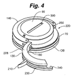
- some embodiments include a die holder 70 with a clamp portion 130 that is hingedly joined (e.g., about a hinge 228) to a wall portion 140 such that the clamp and wall portions can be moved between the closed configuration, as shown in Figure 2 , and the open configuration, as shown in Figures 3 and 4 , by pivoting the clamp portion 130 relative to the wall portion 140.
- the clamp portion 130 can optionally be a concave clamp portion
- the wall portion 140 can optionally be a concave wall portion, or both.
- the clamp portion 130 includes a latch 230, and the latch is hingedly joined to the clamp portion and has a free end 240 that can be hooked onto a catch 250 on the wall portion 140.
- the illustrated latch 230 has a generally arcuate shape, although this is not required.
- the clamp portion also includes an actuator 210 connected to the latch 230 (optionally connected pivotably) and adapted to pull the free end 240 of the latch 230 tight against the catch 250 on the wall portion 140 as part of the clamping operation.
- This exemplifies embodiments where the die holder 70 is adapted for being clamped and unclamped without any assembly or disassembly of the die holder.
- one group of embodiments provides a die holder adapted for being clamped and unclamped without any assembly or disassembly. Another embodiment of this nature is shown in Figure 17 .
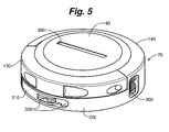
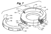
- the closed configuration involves the clamp portion 130 being attached removably to the wall portion 140, as exemplified in Figures 5 , 8 , 9 , 12 , 13 , 33 , 40 , 43 , and 44
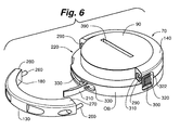
- the open configuration involves the clamp portion being removed from (e.g., completely separated from) the wall portion, as exemplified in Figures 6 , 7 , 10 , 11 , 16 , 34 , 39 and 41 .
- the die holder in some embodiments can be adjusted from the open configuration to a closed configuration, and vice versa, without using any tool.
- the clamp portion 130 has two clamp posts 260 extending respectively from each of its two ends 270, 280.
- the illustrated wall portion 140 has corresponding clamp post apertures 290 adapted to receive the clamp posts 260 when the die holder 70 is placed in the closed configuration.
- This arrangement can optionally be reversed (e.g., the clamp posts can extend from the ends of the wall portion, and the post-receipt apertures can be formed in the ends of the clamp portion), or one end of the clamp portion can have a post while the other end of the clamp portion has a post-receipt aperture adapted to receive a post extending from the wall portion.
- Other variations of this nature are anticipated.
- one or more pinch plates (e.g., a stack of contiguous pinch plates) 300 can be included in the die holder's wall portion 140, as shown best in Figure 8 .
- the pinch plates 300 can have pinch plate apertures 310 aligned with the clamp post apertures 290.
- First and second pinch plate springs 320, 322 can movably hold the pinch plates within a recess defined by the wall portion 140.
- the pinch plate springs 320, 322 hold the illustrated pinch plates 300 in a substantially perpendicular orientation relative to an axis of the clamp post apertures 290 such that the clamp post apertures 290 are aligned (e.g., share a common axis) with the respective pinch plate apertures 310.
- the pinch plate apertures 310 are positioned and sized to receive respective posts 260. For example, when the pinch plates are in a substantially perpendicular orientation relative to the axis of the clamp post aperture 190, the clamp posts can be readily moved through the clamp post apertures 290 and into the pinch plate apertures 310.
- the pinch plates 300 can optionally pull the clamp portion 130 tighter against the wall portion 140 so as to clamp the die holder securely on a die mounted therein.
- the binding forces preferably are large enough to retain the die within the die holder during metal fabrication operations.
- the die holder 70 includes an actuator (optionally comprising a handle) 210 that is pivotably coupled to the die holder. As the actuator is pivoted, it forces an actuating member 330 to articulate along (e.g., through) a wall of the die holder.
- the actuating member 330 has an end portion 340 that exerts force against the pinch plates 300 as the actuator 210 is pivoted in a desired direction.
- the actuator 210 is pivoted in the desired direction to cause end portion 340 to exert force against the pinch plates 300 so as to bind the clamp posts 260 to the wall portion 140 of the die holder 70.
- the actuator 210 can be pivoted in an opposite direction so that the end portion 340 of the actuating member 330 moves away from the pinch plates 300, allowing the springs 320, 322 to move the pinch plates 300 back to their default position (preferably a non-skewed position).
- the actuator 210 causes two actuating members to move respectively toward two stacks of pinch plates, as is perhaps best appreciated with reference to Figure 6 .
- a binding-force mechanism like that in Figures 5-8 can be provided with a variety of different actuator types.
- a powered solenoid can be used to push a stack of pinch plates into a skewed position.
- a ratchet-type handle can be adapted for being cranked repetitively in such a way that pneumatic or hydraulic pressure builds within a chamber of the die holder, causing a piston or the like to move the pinch plates into a skewed position.
- Electromagnetic actuators could also be used to push such pinch plates into a skewed position.
- Other embodiments involve such pneumatic, hydraulic, or electromagnetic actuators being adapted to move a moveable body mounted on the clamp portion or wall portion directly against the die to effect clamping.
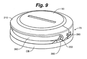
- Figure 9 shows the die holder 70 in the closed and clamped configurations, with a die 90 clamped securely in the interior recess 100 of the die holder 70.
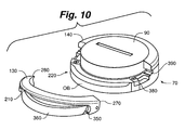
- Figure 10 shows the die holder of Figure 9 in the open and unclamped configurations (here, the die 90 is still mounted on the die holder).
- Figure 11 shows the die holder of Figures 9 and 10 in the open and unclamped configurations after the die has been removed.
- the clamping operation decreases a dimension, such as a diameter, of the die holder's interior recess 100. (This is preferably a result of clamping the die holder in various embodiments.)
- the clamp portion 130 (or a component or section thereof) preferably is forced against the die 90 during the clamping operation.
- Figures 9-12 and 13 exemplify a group of embodiments wherein the die holder has a clamp portion 130 comprising two arcuate bodies (e.g., bars) 210, 360 pivotally joined to each other.
- the two arcuate bodies 210, 360 preferably are resiliently biased so as to assume an expanded configuration unless they are forced to pivot to a compacted configuration.
- the die holder's clamping operation involves one of the two arcuate bodies 210, 360 pivoting relative to the other. This pivoting action can optionally be about an axis at least generally parallel to the die holder's support surface 120.
- the clamp portion 130 includes an actuator 210 adapted to actuate a clamp cam 350, shown best in Figure 12 .
- the clamp cam 350 for example, can be proximate an end portion 270, 280 of the clamp portion 130.
- each end portion of the clamp portion 130 has a clamp cam 350.
- the illustrated actuator 210 is pivotably joined to a clamp bar 360.
- the clamp bar 360 comprises (e.g., is) a spring steel bar.
- the clamp bar 360 can have one or more clamp protrusions 370 extending from each end, as shown best in Figure 12 .
- the die holder 70 can have a clamp shoulder 380 corresponding to each clamp cam 350, and a clamp protrusion receiver (e.g., a recess) 390 corresponding to (e.g., adapted to receive) each clamp protrusion 370.
- a clamp protrusion receiver e.g., a recess
- the die holder is placed in its closed configuration by placing the clamp protrusions 370 in (or proximate to) the corresponding clamp protrusion receivers 390, and then placing (e.g., securing) each clamp cam 350 against its corresponding clamp shoulder 380.
- the clamping operation here includes applying a force (optionally in a generally downward direction) to the actuator 210 so that it tends to pivot relative to the clamp bar 360 in such a manner that each clamp cam 350 articulates against its corresponding clamp shoulder 380 and forces each clamp protrusion 370 further into its corresponding clamp protrusion receiver 390.
- the clamp cam 350 is curved so that, during clamping, it can be articulated to such an extent that an apex 400 of the curve has been articulated against, and forced downwardly past, the contact point with cam shoulder 380.
- the die holder will not release the die until a substantial external force is applied to the actuator 210 in the opposite direction (e.g., in a generally upward direction) to articulate the apex 400 of the clamp cam 350 upwardly past the contact point with the cam shoulder 380.
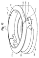
- Figure 13 shows another embodiment of a die holder 70 that includes a clamp portion 130 having a cam 410 with an engagement portion 414.
- the clamp portion 130 includes an actuator 210 that has (e.g., defines) the cam 410.
- the illustrated cam 410 has a generally hook-shaped configuration.
- the actuator is pivotably coupled to a clamp bar 360.
- the clamp bar 360 can optionally comprise (e.g., can be) a spring steel bar.
- the wall portion 140 includes a receiver portion (e.g., a recess) 430 adapted to receive the engagement portion 414 of the clamp portion 130 and a camming surface 420 adapted for articulation against the cam 410.
- the clamp portion 130 is placed against the wall portion 140 such that the engagement portion 414 is proximate (or within) the receiver portion 430 and the cam 410 is proximate or against the camming surface 420.
- a force is applied (e.g., in a generally downward direction) to the actuator 210 to pivot the actuator relative to the clamp bar 360, which causes the cam 410 to articulate against the camming surface 420 so as to force the engagement portion 414 fully into its corresponding recess 430.
- the engagement portion 414 and recess 430 are shaped such that they will not disengage until a substantial force is applied to the actuator in a generally opposite direction (e.g., a generally upward direction).
- Figure 14 shows another die holder embodiment.
- This embodiment includes a clamp portion 130 pivotably coupled with one end of a wall portion 140.
- An actuator 210 is pivotably joined to another end of the wall portion 140.
- the clamp portion 130 is pivoted relative to the wall portion 140 until the free end of the clamp portion abuts (or is simply adjacent to) the wall portion.
- the actuator 210 formed with a latch 230, is pivoted from the opposite end of the wall portion until its latch 230 engages a catch 250 on the clamp portion.
- the catch 250 could be on the actuator 210 and the latch 230 could be on the.clamp portion.
- the latch 230 and catch 250 can respectively include or operate as a cam and camming surface.
- the present embodiment is a doubled-hinged die holder 70.
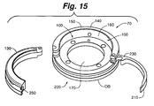
- the clamp portion 130 is detachable from the wall portion 140, as shown in Figure 15 .
- the actuator 210 can also be detachable from the wall portion 140. Further, it is anticipated that the clamp portion could be attached to the right side of the wall portion (as seen in Figure 14 ) and the actuator could be attached to the left side.
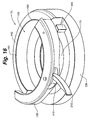
- Figure 16 shows an embodiment of a die holder 70 having a clamp portion 130 with an actuator 210 adapted to cause a cam 410 to cam directly against a surface of a die 90 (not shown in Figure 16 ) so as to clamp the die.
- the die holder 70 can have shoulders 440, and the clamp portion can have corresponding shoulder receivers (not shown in Figure 16 ).
- the clamp portion 130 is set on the die holder 70 such that the shoulders 440 are received within the shoulder receivers.
- the actuator 210 can be actuated (e.g., a handle thereof can be moved) to articulate the cam 410 directly against a surface of the die.
- the cam 410 can be curved to allow it to retain the die within the die holder after it has been articulated to such an extent that an apex of the curve has been articulated against, and forced past, the contact point with the die surface.
- a force can be applied to the actuator in a generally opposite direction to place the die holder in the unclamped configuration.
- Such embodiments can optionally be provided with a removable handle.
- the cam 410 can have an opening (not shown) into which a removable handle can be inserted removably when it is desired to rotate the cam (rather than having the handle be integral to the cam 410 as shown in Figure 16 ).
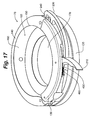
- Figure 17 shows an embodiment of a die holder 70 having a clamp portion 130 hingedly connected to the wall portion 140.
- the embodiment of Figure 17 also includes an actuator 210 coupled to a latch 230.
- a free end 240 of the latch 230 can engage a portion of (e.g., a pin or other catch on) the wall portion, and the actuator 210 can then be pivoted relative to the latch 230 to perform the clamping operation.
- a base end of the latch 230 can be coupled to a rod 450 proximate the actuator 210.
- the rod 450 can be received within a spring 460.
- the actuator 210 is closed during the clamping operation, the end of the latch 230 pushes the rod 450 to compress the spring 460.
- the spring 400 serves to hold the actuator in both the open and closed configurations.
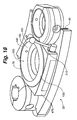
- Figure 18 shows an embodiment of a table 40 of a press 20 carrying a plurality of die holders.
- the middle die holder 70 has a concave clamp portion 130, a concave wall portion 140, and a single-motion actuator 210.
- This embodiment illustrates that the outer surface 470 of the die holder can take any shape.
- the terms "concave wall portion” and “concave clamp portion” refer to the concave interior surfaces of those components: the exteriors of those components need not be concave.
- Figure 19 shows an embodiment of a die holder 70 having an actuator 210 with a removable handle portion 480 and a base portion 490.
- the handle portion 480 can be received removably within the base portion 490, and the actuator 210 can be actuated to perform the clamping operation.
- a removable handle can be provided for other embodiments as well.
- the handle in Figure 16 can be removable in much the same manner as the handle in Figure 19 .
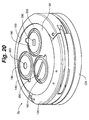
- Figure 20 shows a die holder 70 with its clamp portion 130 and wall portion 140 in the closed and clamped configurations holding a die 90 that is a die cassette 500.
- the die cassette 500 is adapted to receive a plurality of smaller dies 190. It should be noted that the die cassette 500 can be utilized with any embodiment of the present invention. Thus, a die cassette is considered to be a "die" for purposes of this disclosure,
- some embodiments involve an opening 390 that extends entirely through the die. This, however, is not the case in all embodiments.
- Figures 37 and 38 depict exemplary embodiments wherein the die holder is adapted to hold a polygonal die.
- the illustrated die 90 has a generally square configuration.
- the die holder's interior recess 100 has a generally square configuration. Virtually any desired configurations can be used for the die holder's interior recess 100 and the die 90.
- the die holder 70 of Figures 37 and 38 has a wall portion 140 and a clamp portion 130.
- the illustrated clamp portion 130 is joined pivotally to the wall portion 140.
- the die can be moved through the die holder's open side 220 into the interior recess 100.
- the clamp portion 130 can then be pivoted relative to the wall portion 140 until the die holder reaches its closed configuration.
- a latch 230 on the clamp portion 130 is extended so as to attach a hook 240 on the free end of the latch to a catch (e.g., a post, pin, or other suitable structure) 250 on the wall portion 140.
- An actuator 210 on the die holder is operably coupled (e.g., pivotably attached) to the latch 230.
- the latch 230 is pulled tight against the catch 250 on the wall portion 140, thereby causing the clamp portion 130 to clamp on the die 90.
- Figure 38 shows the die 90 in the resulting clamped position.
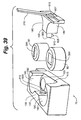
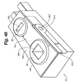
- Figures 39 and 40 depict an exemplary embodiment wherein the die holder 70 is adapted to clamp a plurality of dies 90 simultaneously.
- Figures 39 and 40 also exemplify embodiments wherein the die holder 70 has a configuration that can be characterized as being generally pie-shaped.
- the die holder 70 has a clamp portion 130 and a wall portion 140.
- the die holder 70 here has an actuator 210, which when actuated is adapted to cause the clamp portion 130 to simultaneously clamp two dies 90 mounted on the die holder.
- the clamp portion 130 has two generally opposed concave surfaces 180, which are adapted to respectively engage the two dies 90 mounted on the die holder.
- the clamp portion 130 has a generally T-shaped cross-sectional configuration (e.g., in a cross-section taken parallel to the die holder's shelf 110 and/or support surface 120). Other configurations can alternatively be used.
- the actuator 210 on the die holder 70 of Figures 39 and 40 comprises a handle (on the clamp portion) that moves pivotally to effect clamping and unclamping.
- the actuator 210 here comprises a bar 910, a first end 902 of which is adapted to be received axially in a corresponding recess 810 in the die holder's wall portion 140.
- the first end 902 of the bar 910 is equipped with a transverse pin, which is adapted to be received in a corresponding recess 805 open to recess 810.
- the actuator 210 can be pivoted to clamp the die holder. In more detail, pivoting the actuator 210 causes the bar 910 to rotate about its axis.
- the illustrated actuator 210 is a handle. However, a rotatable knob or the like could alternatively be used.
- the die holder is moved between open and closed configurations, and/or between clamped and unclamped configurations, automatically (i.e., without manually manipulating the die holder, or without any direct human contact).
- an automatic actuator actuated by electrical, hydraulic, and/or pneumatic power can be utilized for automatically configuring the die holder. Controls for such an automatic actuator can be included with the fabricating press or a control panel.
- a programmable robot e.g., a robotic arm
- the various die holder embodiments described above can be configured on a press such that they can be clamped and/or unclamped pneumatically, hydraulically, etc.
- Some embodiments of the fabricating press include a table (optionally a turret table) with a plurality of die holders.
- each die holder can optionally be an independently-operable die holder such that performing a clamping operation clamps a single die holder alone and does not simultaneously clamp any other tool holder (e.g., any other die holder), and/or such that performing an unclamping operation unclamps the die holder alone and does not simultaneously unclamp any other tool holder.
- any of the fabricating presses or die holders described herein can include means to indicate that the die is received within, and securely clamped in, the die holder.
- two electrical contacts can be included within the interior recess and a voltage potential can be applied between the two contacts.
- the contacts can be configured to allow the circuit to be completed only upon successful clamping of the die within the die holder.
- the completed circuit could be used to signal an indication light (or other means) on the die holder, on a fabricating press, or on a control panel to indicate the die is either clamped or unclamped.
- the press, a controller thereof, etc. can be set-up such that it will not initiate pressing operations unless the die holder registers that a (or each) die therein is securely clamped.
- the system can be adapted to indicate whether the correct die is received in the die holder. If the correct die is not in the die holder, the controller can be set-up such that it will not initiate pressing. Any signals transmitted among the die holder, a press (e.g., a controller thereof), and a die can be sent by wire or by wireless RF means.
- a press e.g., a controller thereof
- a die can be sent by wire or by wireless RF means.
- an operator wishing to remove or exchange a die 90 from a fabricating press 10 may do so by first adjusting the die holder 70 from a clamped to an unclamped configuration and from a closed to an open configuration. The die 90 can then be removed from the die holder 70. Another die 90 can be then be placed within the die holder 70, and the die holder can be adjusted to a closed and clamped configuration.
- Figures 41-44 exemplify various die holder embodiments.
- the actuator 210 allows the die holder to be unclamped in response to a single motion of the actuator.
- the actuator shown here is a latch, although any other single-motion actuator can be used.
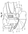
- the unclamping operation can be performed by simply pulling the latch outwardly, e.g., moving it from the latch position shown in Figure 43 to the latch position shown in Figure 44 .
- This movement of the latch causes the two engagement bodies (which are locking pins in the illustrated embodiment) to move from their locked position to an unlocked position.
- the latch 210 here is mounted pivotally (e.g., on a pivot pin PP) on the clamp portion 130 of the die holder.
- the illustrated locking pins are resiliently biased (e.g., by respective compression springs CSP) such that when they are aligned with corresponding locking recesses LOR, they move into locking engagement with those recesses.
- springs CSP move the locking pins LP in this manner, cam surfaces PCS on the locking pins LP bear against (e.g., cam with) corresponding camming surfaces 750 bounding the locking recesses LOR, such that the clamp portion 130 is urged toward the wall portion 140.
- the latch can be moved to the latch position shown in Figure 44 .
- part of the latch e.g., an actuating portion 222
- part of the latch e.g., an actuating portion 222
- the actuating portion 222 (which is shown as being an actuating pin) of the latch lifts upwardly against a lifting surface 313 on each locking pin LP during the unclamping process.
- the angle of the cam surfaces PCS on the locking pins LP and that of the corresponding camming surfaces 750 bounding the locking recesses LOR may range from 1 to 20 degrees from vertical, perhaps optimally being from 2 to 10 degrees from vertical. This, however, is by no means required in other embodiments. Moreover, the noted angle contemplates the die holder being mounted on a horizontal plane, and that is not required.
- Figures 41-44 exemplify embodiments wherein the die holder is adapted to be adjusted from an unclamped, open configuration to a closed, clamped configuration by performing a single step that comprises pushing together the clamp and wall portions.
- the single step is a tool-free operation, although this is not strictly required.
- the wall portion 140 of the die holder may be mounted on a table of a press. Once a die is placed on the die holder's support surface 120, the clamp portion 130 can be pushed (e.g., in a sideways manner, such as in a horizontal direction) onto the wall portion 140 until the locking pins LP move into locking engagement with the locking recesses LOR.
- a bottom surface ACS of each locking pin LP can be tapered, and corresponding angled ramp surfaces RMP can be provided between the outside edge of the die holder's opening base OB and the locking recesses LOR.
- angled bottom surfaces ACS of the locking pins LP ride easily over the angled ramp surfaces RMP to prevent the locking pins from getting hung-up on the outside edge of the die holder's opening base.
- Figures 41-44 show the angle of the ramp (from horizontal) being about 25 degrees. More generally, a range of about 20-30 degrees may be suitable.
- the angle (from horizontal) of the bottom surface ACS of each locking pin LP also has an of about 25 degrees, and a range of about 20-30 degrees may be suitable.
- two springs CSP are shown respectively on the two locking pins LP. In one practical example, these springs have a total rate of 6 pounds. More generally, a range of about 5-20 pounds may be suitable.
- the embodiment of Figure 41 also shows a return spring ACS (although multiple return springs may be desirable).
- the illustrated return spring 601 may have a rate of about 2-10 pounds, such as about 2 pounds in a practical example.
- the opening base OB can be made from a hardenable tool steel such as A2 or pre hard tool steel material such as 4130, then turned on a lathe or turning center to the approximate inner and outer diameters, and then either heat treated for hardness or if a prehard material is used hardening is not required, in either case the unit can be placed in a milling machine after the lathe operation and the front opening portion can be milled, then the pocket features and finish details can be added to the part.
- An added surface preparation such as nitrocarburizing, may be added for surface hardening and or lubricity.
- the illustrated locking recesses LOR may be heat treated with either induction hardening or laser hardening for added durability.
- the opening base OB can be made on a multi axis machine center to avoid costly set up.
- the clamp portion 130 can be made in a similar fashion as the opening base OB, although multiple set-ups may be required to achieve the recess area on the top surface and the pocket openings for the illustrated actuator 210 and lifting pins LP.
- the clamp Portion 130 can be made from a hardenable spring steel such as S2 to enable the clamp portion 130 to spring open to engage the die then embrace a die for removal.
- the actuator 210 can be made with conventional machines such as a mill or can be made by wire EDM (electrical discharge machining) or waterjet. The actuator 210 could also be made by metal injection molding, plastic injection molding or casting.
- the lifting pins LP can be made from hardenable tool steel such as A2 or D2, and can be turned on a turning center then milled to the correct shape and angle on the ends that engage the locking recesses LOR.
- the lifting pins LP can be hardened after the lathe and mill work is complete, and then ground to a proper fit in the clamp portion 130.
Landscapes
- Engineering & Computer Science (AREA)
- Mechanical Engineering (AREA)
- Punching Or Piercing (AREA)
- Mounting, Exchange, And Manufacturing Of Dies (AREA)
- Bending Of Plates, Rods, And Pipes (AREA)
Description
- The present invention is in the field of die holders for machine tools. More particularly, this invention relates to die holders for metal-fabricating presses.
- Metal-fabricating presses, such as turret presses, single-station presses, etc., are used to fabricate sheet metal and other sheet-like workpieces. Commonly, each press includes an upper table and a lower table, and at least one die holder adapted for holding a die securely between the upper and lower tables. In many cases, the die holder is adapted to tightly hold the die with a plurality of set screws. In order to change out a die, the set screws must be loosened before the old die can be removed. Then, the new die can be loaded into the die holder (e.g., after moving the new die into the space between the upper and lower tables). The upper and lower tables of many presses are relatively close together. Thus, replacing dies can be a difficult and time consuming process. In addition, after a pressing operation, the die can be hard to remove from the die holder due to stiction. Stiction occurs when the die becomes stubbornly stuck in the die holder (e.g., due to a close fit between the die and the die holder, and any lubrication present). Stiction causes additional difficulty because the die must be forced from the die holder.
-
WO 99/01240 -
EP 1447154 discloses a punch press employing cartridges which hold tools. Cartridge holding means are supported by a punch frame and have cartridge clamps. - The invention provides a die holder for a fabricating press. The die holder defines an interior recess configured to receive a die. The die holder includes a clamp portion and a wall portion. The clamp and wall portions are adapted to be positioned in an open configuration or a closed configuration. The clamp and wall portions together surround the interior recess when in the closed configuration. The die holder can be adjusted from a clamped configuration to an unclamped configuration by performing an unclamping operation. When the die is received in the interior recess and the die holder is in the clamped configuration, the die is clamped securely by the die holder. The die holder according to the invention is provided with a single-motion actuator that allows the unclamping operation to be performed in response to a single motion of the actuator.
- In some embodiments, the die holder preferably is provided with a tool-free actuator that allows both the clamping and unclamping operations to be tool-free operations.
- The invention provides a die holder for a fabricating press. The die holder defines an interior recess configured to receive a die. The die holder includes a clamp portion and a wall portion. In some embodiments, the die holder preferably is adapted to be adjusted from an unclamped, open configuration to a closed, clamped configuration by performing a single step that comprises pushing together the clamp and wall portions.
- The invention provides a method of using a die holder. The die holder defines an interior recess in which a die is provided. The die holder includes a clamp portion and a wall portion.
- The method comprises adjusting the die holder from an unclamped, open configuration to a closed, clamped configuration by performing a single step that comprises pushing together the clamp and wall portions.
- In one group of embodiments, the invention provides a die holder. The die holder defines an interior recess configured to receive a die. The die holder includes a clamp portion and a wall portion. In some embodiments, the clamp portion is adapted to embrace the die such that when the clamp portion is moved away from the wall portion the die moves together with the clamp portion away from the wall portion. In some cases, the interior recess has a generally circular configuration, the clamp portion has a concave interior surface, the wall portion has a concave interior surface, and these interior surfaces are adapted to engage the die when the die holder is clamped securely on the die.
- In some embodiments, the die holder has an open configuration that involves a side of the die holder being open. Such die holders are useful, for example, for mounting and dismounting dies in a confined space, such as between the upper and lower tables of a press. Such die holders can be configured to allow a die to be easily inserted in, or removed from, the die holder from the perimeter of the press. This may avoid the need of having to lift a die upwardly during removal from the die holder, which may be difficult due to the limited space between the tables of the press.
- According to the invention, the die holder can be adjusted from an unclamped configuration to a clamped configuration by performing a clamping operation, and the die holder can be adjusted from the clamped configuration to the unclamped configuration by performing an unclamping operation. Preferably, when the die is received in the interior recess and the die holder is in the clamped configuration, the die is clamped securely by the die holder. According to the invention, the die holder is provided with a single-motion actuator, such that the die holder is adapted to clamp in response to a single motion of the actuator.
- In some embodiments, when the clamp and wall portions are positioned in the open configuration, the die can be mounted in the die holder by moving the die sideways through an open side of the die holder, after which the clamp and wall portions can be positioned in the closed configuration and then the clamping operation can be performed to securely clamp the die holder on the die.
-
-
Figure 1 is a schematic, broken-away perspective view of a fabricating press in accordance with an embodiment of the invention. -
Figure 2 is a perspective view of a die and a die holder in accordance with an embodiment of the invention. -
Figure 3 is a perspective view of the die holder ofFigure 2 in an open configuration in accordance with an embodiment of the invention. -
Figure 4 is a perspective view of the die and die holder ofFigure 2 in an open configuration in accordance with an embodiment of the invention. -
Figure 5 is a perspective view of a die and a die holder in accordance with another embodiment of the invention. -
Figure 6 is a perspective view of the die and die holder ofFigure 5 in an open configuration in accordance with an embodiment of the invention. -
Figure 7 is a perspective view of the die holder ofFigure 5 in an open configuration in accordance with an embodiment of the invention. -
Figure 8 is a side detail view of a portion of the die holder ofFigure 5 in accordance with an embodiment of the invention. -
Figure 9 is a perspective view of a die and a die holder in accordance with another embodiment of the invention. -
Figure 10 is a perspective view of the die and die holder ofFigure 9 in an open configuration in accordance with an embodiment of the invention. -
Figure 11 is a perspective view of the die holder ofFigure 9 in an open configuration in accordance with an embodiment of the invention. -
Figure 12 is a partially broken-away side view of a portion of the die and the die holder ofFigure 9 in accordance with an embodiment of the invention. -
Figure 13 is a perspective view of a die holder in accordance with another embodiment of the invention. -
Figure 14 is a perspective view of a die holder in accordance with another embodiment of the invention. -
Figure 15 is a perspective view of the die holder ofFigure 14 in a disassembled configuration in accordance with an embodiment of the invention. -
Figure 16 is a perspective view of a die holder in accordance with another embodiment of the invention. -
Figure 17 is a perspective view of a die holder in accordance with another embodiment of the invention. -
Figure 18 is a perspective view of a press table with a plurality of die holders in accordance with another embodiment of the invention. -
Figure 19 is a perspective view of a die holder with a removable handle in accordance with another embodiment of the invention. -
Figure 20 is a perspective view of a die holder with a die cassette and a plurality of dies in accordance with another embodiment of the invention. -
Figure 21 is a perspective view of a die holder with a die-release mechanism in accordance with an exemplifying, embodiment which is not part of the invention. -
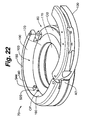
Figure 22 is a perspective view of a die holder with a die-release mechanism in accordance with another exemplifying embodiment which is not part of the invention. -
Figure 23 is a top plan view of the die holder ofFigure 22 . -
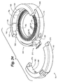
Figure 24 is a schematic, broken-away top plan view of a portion of a die holder having a die-release mechanism in accordance with certain exemplifying embodiments which are not part of the invention. -
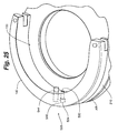
Figure 25 is a broken-away hidden line perspective view of a die holder having a die-release mechanism in accordance with certain exemplifying embodiments which are not part of the invention. -
Figure 26 is a broken-away partial side cut-away view of a die holder with a die-release mechanism in accordance with another exemplifying embodiment which is not part of the invention. -
Figure 27 is a broken-away partial perspective cut-away view of the die holder with the die-release mechanism ofFigure 26 in accordance with an exemplifying embodiment which is not part of the invention. -
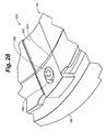
Figure 28 is a broken-away partial perspective view of the die holder with the die-release mechanism ofFigure 26 in accordance with an exemplifying embodiment which is not part of the invention. -
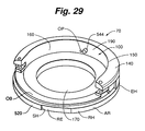
Figure 29 is a perspective view of a die holder in a disassembled configuration in accordance with certain embodiments of the invention. -
Figure 30 is a broken-away, schematic cross-sectional side view of a fabricating press involved in certain embodiments of the invention. -
Figure 31 is a schematic broken-away top view of a turret press involved in certain embodiments of the invention. -
Figure 32 is a schematic broken-away perspective view of one exemplary manner in which a die holder can be mounted on a table of a fabricating press. -
Figure 33 is a perspective view of a die holder in a closed and clamped configuration in accordance with certain exemplifying embodiments which are not part of the invention. -
Figure 34 is a perspective view of the die holder ofFigure 33 in an open configuration. -
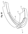
Figure 35 is a perspective view of a clamp portion of the die holder ofFigure 34 . -
Figure 36 is a broken-away schematic cross-sectional side view of the die
holder ofFigure 33 . -
Figure 37 is a perspective view of a die holder and die in accordance with certain embodiments of the invention. -
Figure 38 is a perspective view of the die holder and die ofFigure 37 , with the die holder clamped on the die. -
Figure 39 is a perspective view of a multiple-track die holder and two dies in accordance with certain embodiments of the invention. -
Figure 40 is a perspective view of the die holder and dies ofFigure 39 , with the die holder clamped on the dies. -
Figure 41 is an exploded perspective view of a die holder in accordance with certain embodiments of the invention. -
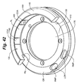
Figure 42 is a perspective view of a portion of the die holder ofFigure 41 . -
Figure 43 is a broken-away partial perspective view of the die holder ofFigure 41 , showing an actuator of the die holder in a locked position. -
Figure 44 is a broken-away partial perspective view of the die holder ofFigure 43 , showing the actuator in an unlocked position. - The following detailed description is to be read with reference to the drawings, in which like elements in different drawings have like reference numerals. The drawings, which are not necessarily to scale, depict selected embodiments and are not intended to limit the scope of the invention. Skilled artisans will recognize that the given examples have many useful alternatives.
- Some embodiments of the invention provide a die holder for a fabricating press, such as a metal-fabricating press. In some cases, the press has an upper table and a lower table. A gap between the upper and lower tables is adapted to receive sheet metal or another sheet-like workpiece. In some cases, the upper table may be omitted. The lower table preferably is adapted to have mounted thereon at least one die holder (a
wall portion 140 of the die holder may be mounted fixedly on the table, and aclamp portion 130 of the die holder may, in some cases, be adapted for being removably attached to the wall portion). The lower table commonly has a horizontal surface on which the die holder can be mounted and/or defining a mount opening in which the die holder can be mounted. The mount opening in such a press can optionally have a generally circular configuration. In other cases, the mount opening is adapted to receive a polygonal (e.g., generally square) die holder. - One type of fabricating press is shown in
Figure 1 . Here, thepress 10 is a turret press, although the fabricatingpress 10 can be a single-station press or any other fabricating press. The fabricatingpress 10 can include any machine useful for the fabrication of sheet-like workpieces, such as sheet metal or other metal parts. The fabrication process itself can include any work step, such as punching holes, creating bends, various forms, etc. - In some embodiments, the fabricating
press 10 includes (e.g., is) aturret press 20. In such embodiments, theturret press 20 can include an upper table (e.g., an upper turret) 30 and a lower table (e.g., a lower turret) 40. The upper table 30 and lower table 40 can be separated by aturret gap 50 adapted to receive sheet-like workpieces. Theturret press 20 can include a plurality of stations (reference is made toFigure 31 ), at least one of which is adapted to receive adie holder 70. In some embodiments, thedie holder 70 is adapted for being removably mounted in anopening 80 defined by a table of the fabricatingpress 10. (The embodiment shown inFigure 1 has such openings in the lower table 40, but they are not visible becausedie holders 70 have been mounted therein). In other cases, the die holder is not potted in an opening defined by the lower table, but is bolted or otherwise anchored removably to the table (such as in the same general manner shown inFigure 32 ). Awall portion 140 of thedie holder 70 can optionally be mounted in a stationary position on the table. Metal sheets and/or other workpieces (including non-metal sheets and other non-metal workpieces requiring bends, holes, forms, or other fabrication) can be placed between the upper and lower turrets, and a punch or other tool mounted on the upper turret (seeFigure 30 ) may be caused to act against the workpiece, forcing the workpiece against the die for fabrication. The lower and upper tables may be adapted to rotate together to allow any desired tool set to be moved into position to act on the workpiece. In such presses, the dies are changed periodically to accommodate different fabrication operations, and to replace worn dies. - For embodiments involving a turret press (or other presses with upper and lower tables separated by a gap), to mount a
die 90 within thedie holder 70, the die can be moved into the gap and mounted in the die holder. - In some embodiments, the die can be moved into the die holder through an open side of the die holder. The open side (which preferably can be closed once the die is mounted on the die holder) may optionally be bounded underneath by an opening base OB of the die holder. The opening base OB, when provided, desirably has a smaller height than the
wall portion 140 of the die holder. Preferably, the opening base OB forms part of the die holder'sshelf 110 and defines a portion of thesupport surface 120 that is adapted to support the bottom of a die. When theclamp portion 130 of the die holder is in a closed configuration, the clamp portion preferably is carried against (e.g., positioned on top of) at least part of the opening base OB. - One exemplary embodiment of a die 90 mounted in a
die holder 70 is shown inFigure 2 . Here, the clamping operation results in the die holder clamping a single die, although other embodiments involve the clamping operation causing the die holder to simultaneously clamp on at least two dies.Figures 39 and40 , for example, depict a multiple-track die holder embodiment wherein the clamping operation causes the die holder to simultaneously clamp on two dies. - In some cases, the die holder is used on a single-station fabricating press. In embodiments of this nature, the press typically does not involve turrets, although the press may still have upper and lower tables (or at least a lower table), as is well known in the present art.
- The
die holder 70 can include any apparatus useful for holding adie 90. Preferably, thedie holder 70 has aninterior recess 100. Theinterior recess 100 may have a generally circular configuration (and/or it may be adapted to receive a die having a generally circular configuration). This, however, is not the case in all embodiments. For example, other embodiments involve apolygonal die 90 and a polygonalinterior recess 100. Polygonal dies of the Salvagnini style are known, and the present die holder can be configured to accommodate such dies.Figures 37 and38 depict one embodiment of adie holder 70 adapted to retain a polygonal (e.g., generally square) die. Embodiments like that ofFigures 37 and38 are described below in more detail. - The die holder preferably has a
shelf 110 adapted to support a bottom (e.g., a planar base) of adie 90. Reference is made toFigure 3 . The shelf, for example, can have (e.g., can define) asupport surface 120 on which the bottom of a die is adapted to rest (e.g., when the die is operably mounted in the die holder). In some embodiments, the die holder has ashoulder 150 defining at least part of the die holder'sinterior side surface 160, which optionally extends at least generally (e.g., substantially) orthogonally from theshelf 110. Theshoulder 150 can bound theinterior recess 100. When the die holder is in a closed configuration, the die holder's interior side surface 160 (at least part of which preferably is defined by the shoulder 150) can optionally entirely surround theinterior recess 100. Further, thedie holder 70 can have a central opening 170 (optionally one through which slugs of workpiece material can drop during certain metal fabrication operations), and theshelf 110 can encompass (e.g., can optionally entirely surround) thecentral opening 170. In some cases, the die holder has an opening base OB one side of which bounds thecentral opening 170 and another side of which defines an outer perimeter of the die holder. - In some embodiments, the
die holder 70 includes aclamp portion 130 and awall portion 140. Theclamp portion 130 can optionally comprise (e.g., can be) a concave clamp portion (i.e., it can optionally have a concave interior surface). The clamp portion, for example, can have a generally C-shaped configuration as shown in many of the drawings. Additionally or alternatively, thewall portion 140 can optionally comprise (e.g., can be) a concave wall portion. - In some embodiments, the
clamp portion 130 andwall portion 140 cooperate to allow thedie holder 70 to have a closed configuration, embodiments of which are shown inFigures 1 ,2 ,5 ,8 ,9 ,12 ,13 ,17 ,20 ,21 ,33 ,36 ,38 ,40 ,43 , and44 , and an open configuration, embodiments of which are shown inFigures 3 ,4 ,6 ,7 ,10 ,11 ,14-16 ,22 ,23 ,34 ,37 ,39 , and41 . Preferably, in the closed configuration, theclamp 130 and wall 140 portions together surround the interior recess 100 (optionally entirely surrounding the interior recess, substantially entirely surrounding the interior recess, or surrounding the interior recess to such an extent that a die cannot be mounted in the die holder by simply sliding the die sideways through any side opening). In the open configuration, thedie holder 70 preferably is configured to allow a die 90 to be placed in thedie holder 70 or removed from thedie holder 70. In some embodiments, when theclamp 130 and wall 140 portions are positioned in the closed configuration, thedie holder 70 has a generally annular configuration (and/or at least has a generally circularinterior side surface 160 surrounding the interior recess 100). In some embodiments, the die holder has configurations like those shown inFigures 18 ,19 , or37-40 . Other die holder configurations can also be provided with the features of any embodiment described in the present disclosure. - The terms "concave clamp portion" and "concave wall portion" do not require the whole of either component to be concave. Preferably, though, a
concave clamp portion 130 has a concaveinterior surface 180, and aconcave wall portion 140 has a concaveinterior surface 190. Those interior surfaces are adapted to surround, abut, and/or engage a die 90 when the die is mounted in thedie holder 70 and the die holder is in the closed configuration. - In some embodiments, a concave
interior surface 180 of theclamp portion 130 bounds at least 30 degrees, at least 35 degrees, or at least 40 degrees of theinterior recess 100 when the clamp and wall portions are in the closed configuration.Figures 33-36 and41-44 exemplify embodiments wherein thedie holder 70 has a clamp portion 130 (optionally defining a concave interior surface 180) that encompasses more than 180 degrees of theinterior recess 100. Embodiments of this nature can be particularly advantageous. For example, such aclamp portion 130 can be sized to press fit on, or otherwise embrace, a die such that the clamp portion retains the die when the clamp portion is pulled off (e.g., moved sideways apart from) thewall portion 140. In such embodiments, when the clamp portion is pulled apart from the wall portion (at such time as a die is mounted in the die holder), the clamp portion holds the die (e.g., holds an exterior sidewall of the die) such that the die and the clamp portion move together away from the die holder's wall portion. The present invention covers any die holder that has this functionality, regardless of the details on how the die holder is able to embrace the die. - In certain embodiments, the
die holder 70 also has a clamped configuration, embodiments of which are shown inFigures 1 ,2 ,5 ,8 ,9 ,12 ,13 ,20 ,21 ,33 ,36 ,38 ,40 , and43 , and an unclamped configuration, embodiments of which are shown inFigures 3 ,4 ,6 ,7 ,10 ,11 ,14-16 ,22 ,23 ,34 ,37 ,39 , and41 (also in the open configuration) and inFigures 17 and44 (also in the closed configuration). The clamped configuration is useful for securely clamping a die 90 in thedie holder 70. The unclamped configuration is useful for allowing thedie holder 70 to be reversibly placed in either the open configuration or the closed configuration. In some embodiments, the die holder can be adjusted from an unclamped configuration to a clamped configuration by performing a clamping operation, and thedie holder 70 can be adjusted from the clamped configuration to the unclamped configuration by performing an unclamping operation. - In certain embodiments, the
die holder 70 includes at least one spring component. Preferably, the spring component is adapted to generate at least part of the clamping force the die holder places on the die. In some cases, the spring component comprises at least one compression spring CSP, optionally provided on theclamp portion 130. Reference is made toFigures 41-44 . These figures exemplify embodiments wherein the die holder includes at least one engagement body (e.g., at least one axially-moveable locking pin) that is moveable between locked and unlocked positions. When provided, the engagement body preferably is in the locked position when the die holder is in a clamped position, and the engagement body preferably is in an unlocked position when the die holder is in an unclamped position. In some cases, the (or each) engagement body is resiliently biased (e.g., by a compression spring or other spring component), optionally toward the locked position. For example, the (or each) engagement body may be extendable and retractable, and may be resiliently biased toward an extended position. - In
Figures 41-44 , there are two engagement bodies (it may be desirable to have a plurality of engagement bodies). The engagement bodies shown inFigures 41-44 comprise locking pins adapted to move axially, e.g., between extended and retracted positions (such as between locked and unlocked positions). Here, the illustrated locking pins are adapted to move along a vertical axis, i.e., if the die holder is mounted on a horizontal plane. This, however, is not required. For examples, it may be desirable to have one or more locking pins or other engagement members tipped at an angle. This may provide advantages, including stronger clamping force or a more secure clamp. Thus, in some embodiments, at least one locking pin or other engagement member is adapted to move along an axis that is oblique to vertical. - In certain embodiments, the die holder includes a spring component having a body comprising (e.g., formed of) spring steel. For example, a spring steel body (optionally having an arcuate shape) can form at least part of the die holder's
clamp portion 130. During a clamping operation, thedie holder 70 can apply a clamping force on a die 90 (when the die is in the die holder's interior recess 100) and the optional spring steel body may generate at least part of the clamping force. In such embodiments, when the clamp and wall portions are in the closed configuration, a clamping operation preferably can be performed so as to decrease a dimension, such as a diameter, of the interior recess (more generally, this can optionally be the case for various embodiments described in this disclosure). - In many embodiments, the die holder includes an
actuator 210. In some of these embodiments, the actuator is adapted to be moved (e.g., manually, or in some cases robotically or otherwise using hydraulics, pneumatics, electronics, magnetics, or the like) in such a way as to move the die holder between clamped and unclamped configurations. In some cases, the actuator is adapted to be moved in one manner (e.g., in one direction) so as to adjust the die holder from an unclamped position to a clamped position, and the actuator can be moved in a different manner (e.g., in a different direction) so as to adjust the die holder from a clamped position to an unclamped position. This, however, is not the case for all embodiments. - In one group of embodiments, the die holder is provided with an
actuator 210 comprising a body that moves relative to theclamp portion 130 and/orwall portion 140 during clamping and/or unclamping operations. This moveable body can optionally be a pivotable body that moves pivotally (e.g., about at least one hinge) during the clamping and/or unclamping operations. The pivotable body, for example, can be a handle or a latch.Figures 33-36 and41-44 depict exemplary embodiments involving a latch. - In certain embodiments, the
actuator 210 is a tool-free actuator that allows the unclamping operation, the clamping operation, or both to be tool-free operations (or at least operations that do not involve rotating a set screw or any other threaded fastener). The clamping and/or unclamping operations, for example, may be performed without a wrench or screw driver. Components of the die holder itself, even if removable (e.g., a removable handle actuator), are not considered tools for purposes of the present disclosure. - As described below, some embodiments provide a die holder (which can optionally be a tool-free die holder) that can be clamped and unclamped, and/or adjusted between open and closed configurations, without requiring any assembly or disassembly of the die holder. These embodiments, for example, may involve the die holder having a clamp portion that is pivotally (e.g., hingedly) connected to the die holder's wall portion.
- In certain embodiments, the
actuator 210 is a single-motion actuator that allows thedie holder 70 to be unclamped in response to a single motion of the actuator. (In some of these embodiments, the unclamping operation is also a tool-free operation.) Additionally or alternatively, theactuator 210 can be one that allows the die holder to be clamped in response to a single motion of theactuator 210. In some embodiments of this nature, the die holder must be partially assembled (e.g., the clamp portion may need to be joined to the wall portion, and/or a removable handle may need to be joined to the die holder) before the single-motion clamping can be performed. However, the actual clamping in such embodiments preferably occurs in response to a single motion of a single-motion actuator (the same may be true of the actual unclamping). Exemplary single motions can be pivoting, pressing, sliding, squeezing, or rotating theactuator 210. - In some embodiments, the
die holder 70 is provided with anactuator 210 comprising a body (e.g., a handle) that is moved in one direction (once or repeatedly) during the clamping operation and in another direction (optionally an opposite direction) during the unclamping operation. In embodiments involving adie holder 70 with ashelf 110 defining asupport surface 120 on which the bottom of a die 90 is adapted to rest, the handle or other body can optionally be moveable in a plane that is at least generally parallel (or at least substantially parallel) to the shelfs support surface (such that the handle or other body moves in that plane to cause the clamping and unclamping operations). If such adie holder 70 is on, for example, a horizontal table (optionally a lower table 40, as shown inFigure 1 ) of a fabricatingpress 10, then during clamping and unclamping operations the handle or other body may be adapted to move horizontally. If such a die holder is mounted on a turret press (or another press having a gap between upper and lower tables), then thegap 50 can be a generally horizontal gap, and the single-motion actuator 210 can optionally comprise a handle that is moved at least generally horizontally during clamping and unclamping. Other examples include moving the actuator (optionally a latch or handle thereof) generally orthogonally to the generally horizontal gap (e.g., in a generally upward or downward direction) or at an oblique angle.Figures 41-44 , for example, show a latch that is moved in a plane (e.g., a vertical plane) substantially perpendicular to the die holder'ssupport surface 120 during unclamping operations. InFigures 33-36 , the latch is moved in a plane substantially perpendicular to the die holder'ssupport surface 120 during both clamping and unclamping operations. However, this is not the case in all embodiments. - In certain embodiments, when the clamp and
wall portions die holder 70 by moving the die sideways (in some cases, horizontally) through anopen side 220 of the die holder. Reference is made toFigures 3 ,4 ,6 ,7 ,10 ,11 ,14 ,15 ,16 ,22 ,23 ,34 ,37 ,41 , and42 . Preferably, the clamp andwall portions Figures 1 ,2 ,5 ,9 ,12 ,20 , and38 . - In some embodiments, the die holder can be adjusted (e.g., moved) from an unclamped, open configuration to a closed, clamped configuration by pushing together the clamp and wall portions. For example, in embodiments like that of
Figures 41-44 , this can be done (e.g., in a single step) by pushing the die holder's clamp portion onto the wall portion. Preferably, this is a tool-free operation. More will be said of this later. - In certain embodiments, the die holder is mounted on a table (optionally a horizontal table) of a fabricating press in such a way that when the clamp and
wall portions die holder 70 are in the open configuration, an open side of the die holder faces anexterior perimeter 224 of the metal-fabricatingpress 20. Reference is made toFigure 1 . Such embodiments facilitate easy changing of dies in the press by minimizing the amount of work that must be done in the gap between the upper and lower tables. Various embodiments of thedie holder 70 will now be described in more detail. - As shown in
Figures 2-4 , some embodiments include adie holder 70 with aclamp portion 130 that is hingedly joined (e.g., about a hinge 228) to awall portion 140 such that the clamp and wall portions can be moved between the closed configuration, as shown inFigure 2 , and the open configuration, as shown inFigures 3 and4 , by pivoting theclamp portion 130 relative to thewall portion 140. Here (as in other embodiments), theclamp portion 130 can optionally be a concave clamp portion, thewall portion 140 can optionally be a concave wall portion, or both. - In the embodiment shown, the
clamp portion 130 includes alatch 230, and the latch is hingedly joined to the clamp portion and has afree end 240 that can be hooked onto acatch 250 on thewall portion 140. The illustratedlatch 230 has a generally arcuate shape, although this is not required. The clamp portion also includes anactuator 210 connected to the latch 230 (optionally connected pivotably) and adapted to pull thefree end 240 of thelatch 230 tight against thecatch 250 on thewall portion 140 as part of the clamping operation. This exemplifies embodiments where thedie holder 70 is adapted for being clamped and unclamped without any assembly or disassembly of the die holder. Thus, one group of embodiments provides a die holder adapted for being clamped and unclamped without any assembly or disassembly. Another embodiment of this nature is shown inFigure 17 . - In other cases, the closed configuration involves the
clamp portion 130 being attached removably to thewall portion 140, as exemplified inFigures 5 ,8 ,9 ,12 ,13 ,33 ,40 ,43 , and44 , and the open configuration involves the clamp portion being removed from (e.g., completely separated from) the wall portion, as exemplified inFigures 6 ,7 ,10 ,11 ,16 ,34 ,39 and41 . Thus, even though the clamp and wall portions may be completely separated from each other when the die holder is in an open configuration, the die holder in some embodiments can be adjusted from the open configuration to a closed configuration, and vice versa, without using any tool. - In the embodiment shown in
Figures 5-8 , theclamp portion 130 has twoclamp posts 260 extending respectively from each of its twoends wall portion 140 has correspondingclamp post apertures 290 adapted to receive the clamp posts 260 when thedie holder 70 is placed in the closed configuration. This arrangement can optionally be reversed (e.g., the clamp posts can extend from the ends of the wall portion, and the post-receipt apertures can be formed in the ends of the clamp portion), or one end of the clamp portion can have a post while the other end of the clamp portion has a post-receipt aperture adapted to receive a post extending from the wall portion. Other variations of this nature are anticipated. - In some embodiments, one or more pinch plates (e.g., a stack of contiguous pinch plates) 300 can be included in the die holder's
wall portion 140, as shown best inFigure 8 . Thepinch plates 300 can havepinch plate apertures 310 aligned with theclamp post apertures 290. In such embodiments, when aclamp post 260 is inserted through aclamp post aperture 290, the post moves into apinch plate aperture 310. First and second pinch plate springs 320, 322 can movably hold the pinch plates within a recess defined by thewall portion 140. In an unbiased configuration (e.g., when thedie holder 70 is in the open configuration), the pinch plate springs 320, 322 hold the illustratedpinch plates 300 in a substantially perpendicular orientation relative to an axis of theclamp post apertures 290 such that theclamp post apertures 290 are aligned (e.g., share a common axis) with the respectivepinch plate apertures 310. Preferably, thepinch plate apertures 310 are positioned and sized to receiverespective posts 260. For example, when the pinch plates are in a substantially perpendicular orientation relative to the axis of theclamp post aperture 190, the clamp posts can be readily moved through theclamp post apertures 290 and into thepinch plate apertures 310. To then place thedie holder 70 in the clamped configuration, significant binding forces are applied on the clamp posts 260 when thepinch plates 300 are moved into a skewed position relative to the clamp posts. During the process of applying binding force on the clamp posts, the pinch plates can optionally pull theclamp portion 130 tighter against thewall portion 140 so as to clamp the die holder securely on a die mounted therein. The binding forces preferably are large enough to retain the die within the die holder during metal fabrication operations. - The
pinch plates 300 can be placed into a significantly skewed position relative to the clamp posts in any suitable manner. In the embodiment shown inFigures 5-8 , thedie holder 70 includes an actuator (optionally comprising a handle) 210 that is pivotably coupled to the die holder. As the actuator is pivoted, it forces an actuatingmember 330 to articulate along (e.g., through) a wall of the die holder. The actuatingmember 330 has anend portion 340 that exerts force against thepinch plates 300 as theactuator 210 is pivoted in a desired direction. In more detail, theactuator 210 is pivoted in the desired direction to causeend portion 340 to exert force against thepinch plates 300 so as to bind the clamp posts 260 to thewall portion 140 of thedie holder 70. When it is desired to unclamp the die holder, theactuator 210 can be pivoted in an opposite direction so that theend portion 340 of the actuatingmember 330 moves away from thepinch plates 300, allowing thesprings pinch plates 300 back to their default position (preferably a non-skewed position). In the embodiment ofFigures 5-8 , theactuator 210 causes two actuating members to move respectively toward two stacks of pinch plates, as is perhaps best appreciated with reference toFigure 6 . - A binding-force mechanism like that in
Figures 5-8 can be provided with a variety of different actuator types. For example, a powered solenoid can be used to push a stack of pinch plates into a skewed position. Alternatively, a ratchet-type handle can be adapted for being cranked repetitively in such a way that pneumatic or hydraulic pressure builds within a chamber of the die holder, causing a piston or the like to move the pinch plates into a skewed position. Electromagnetic actuators could also be used to push such pinch plates into a skewed position. Other embodiments involve such pneumatic, hydraulic, or electromagnetic actuators being adapted to move a moveable body mounted on the clamp portion or wall portion directly against the die to effect clamping. - Another embodiment is shown in
Figures 9-12 .Figure 9 shows thedie holder 70 in the closed and clamped configurations, with a die 90 clamped securely in theinterior recess 100 of thedie holder 70.Figure 10 shows the die holder ofFigure 9 in the open and unclamped configurations (here, thedie 90 is still mounted on the die holder).Figure 11 shows the die holder ofFigures 9 and10 in the open and unclamped configurations after the die has been removed. - In the embodiments of
Figures 9-12 , the clamping operation decreases a dimension, such as a diameter, of the die holder'sinterior recess 100. (This is preferably a result of clamping the die holder in various embodiments.) The clamp portion 130 (or a component or section thereof) preferably is forced against the die 90 during the clamping operation. -
Figures 9-12 and13 exemplify a group of embodiments wherein the die holder has aclamp portion 130 comprising two arcuate bodies (e.g., bars) 210, 360 pivotally joined to each other. The twoarcuate bodies arcuate bodies support surface 120. When such aclamp portion 130 is mounted on thewall portion 140 and clamped, it ends-up being in its compacted configuration (and stays in this configuration when the die holder is in the clamped configuration). - In
Figures 9-12 , theclamp portion 130 includes anactuator 210 adapted to actuate aclamp cam 350, shown best inFigure 12 . Theclamp cam 350, for example, can be proximate anend portion clamp portion 130. In the illustrated embodiment, each end portion of theclamp portion 130 has aclamp cam 350. The illustratedactuator 210 is pivotably joined to aclamp bar 360. In some embodiments, theclamp bar 360 comprises (e.g., is) a spring steel bar. Theclamp bar 360 can have one ormore clamp protrusions 370 extending from each end, as shown best inFigure 12 . (Figure 13 depicts another useful configuration for such a protrusion.) Thedie holder 70 can have aclamp shoulder 380 corresponding to eachclamp cam 350, and a clamp protrusion receiver (e.g., a recess) 390 corresponding to (e.g., adapted to receive) eachclamp protrusion 370. - In such embodiments, the die holder is placed in its closed configuration by placing the
clamp protrusions 370 in (or proximate to) the correspondingclamp protrusion receivers 390, and then placing (e.g., securing) eachclamp cam 350 against itscorresponding clamp shoulder 380. In more detail, the clamping operation here includes applying a force (optionally in a generally downward direction) to theactuator 210 so that it tends to pivot relative to theclamp bar 360 in such a manner that eachclamp cam 350 articulates against itscorresponding clamp shoulder 380 and forces eachclamp protrusion 370 further into its correspondingclamp protrusion receiver 390. In some embodiments, theclamp cam 350 is curved so that, during clamping, it can be articulated to such an extent that an apex 400 of the curve has been articulated against, and forced downwardly past, the contact point withcam shoulder 380. At this point, the die holder will not release the die until a substantial external force is applied to theactuator 210 in the opposite direction (e.g., in a generally upward direction) to articulate the apex 400 of theclamp cam 350 upwardly past the contact point with thecam shoulder 380. -
Figure 13 shows another embodiment of adie holder 70 that includes aclamp portion 130 having acam 410 with anengagement portion 414. In this embodiment, theclamp portion 130 includes anactuator 210 that has (e.g., defines) thecam 410. The illustratedcam 410 has a generally hook-shaped configuration. The actuator is pivotably coupled to aclamp bar 360. Here again, theclamp bar 360 can optionally comprise (e.g., can be) a spring steel bar. Thewall portion 140 includes a receiver portion (e.g., a recess) 430 adapted to receive theengagement portion 414 of theclamp portion 130 and acamming surface 420 adapted for articulation against thecam 410. To place the die holder in its closed configuration, theclamp portion 130 is placed against thewall portion 140 such that theengagement portion 414 is proximate (or within) thereceiver portion 430 and thecam 410 is proximate or against thecamming surface 420. To then clamp the die holder, a force is applied (e.g., in a generally downward direction) to theactuator 210 to pivot the actuator relative to theclamp bar 360, which causes thecam 410 to articulate against thecamming surface 420 so as to force theengagement portion 414 fully into itscorresponding recess 430. In some embodiments, theengagement portion 414 andrecess 430 are shaped such that they will not disengage until a substantial force is applied to the actuator in a generally opposite direction (e.g., a generally upward direction). -
Figure 14 shows another die holder embodiment. This embodiment includes aclamp portion 130 pivotably coupled with one end of awall portion 140. Anactuator 210 is pivotably joined to another end of thewall portion 140. To place thedie holder 70 in a closed configuration, theclamp portion 130 is pivoted relative to thewall portion 140 until the free end of the clamp portion abuts (or is simply adjacent to) the wall portion. To then place the die holder in a clamped configuration, theactuator 210, formed with alatch 230, is pivoted from the opposite end of the wall portion until itslatch 230 engages acatch 250 on the clamp portion. Alternatively, thecatch 250 could be on theactuator 210 and thelatch 230 could be on the.clamp portion. Thelatch 230 and catch 250 can respectively include or operate as a cam and camming surface. The present embodiment is a doubled-hingeddie holder 70. Here, theclamp portion 130 is detachable from thewall portion 140, as shown inFigure 15 . Optionally, theactuator 210 can also be detachable from thewall portion 140. Further, it is anticipated that the clamp portion could be attached to the right side of the wall portion (as seen inFigure 14 ) and the actuator could be attached to the left side. -
Figure 16 shows an embodiment of adie holder 70 having aclamp portion 130 with anactuator 210 adapted to cause acam 410 to cam directly against a surface of a die 90 (not shown inFigure 16 ) so as to clamp the die. In the embodiment ofFigure 16 , thedie holder 70 can haveshoulders 440, and the clamp portion can have corresponding shoulder receivers (not shown inFigure 16 ). In such an embodiment, to place the die holder in a closed configuration, theclamp portion 130 is set on thedie holder 70 such that theshoulders 440 are received within the shoulder receivers. To then clamp the die holder, theactuator 210 can be actuated (e.g., a handle thereof can be moved) to articulate thecam 410 directly against a surface of the die. Thecam 410, for example, can be curved to allow it to retain the die within the die holder after it has been articulated to such an extent that an apex of the curve has been articulated against, and forced past, the contact point with the die surface. A force can be applied to the actuator in a generally opposite direction to place the die holder in the unclamped configuration. Such embodiments can optionally be provided with a removable handle. For example, thecam 410 can have an opening (not shown) into which a removable handle can be inserted removably when it is desired to rotate the cam (rather than having the handle be integral to thecam 410 as shown inFigure 16 ). -
Figure 17 shows an embodiment of adie holder 70 having aclamp portion 130 hingedly connected to thewall portion 140. The embodiment ofFigure 17 also includes anactuator 210 coupled to alatch 230. Afree end 240 of thelatch 230 can engage a portion of (e.g., a pin or other catch on) the wall portion, and theactuator 210 can then be pivoted relative to thelatch 230 to perform the clamping operation. In the embodiment ofFigure 17 , a base end of thelatch 230 can be coupled to arod 450 proximate theactuator 210. Therod 450 can be received within aspring 460. As theactuator 210 is closed during the clamping operation, the end of thelatch 230 pushes therod 450 to compress thespring 460. Thespring 400 serves to hold the actuator in both the open and closed configurations. -
Figure 18 shows an embodiment of a table 40 of apress 20 carrying a plurality of die holders. Themiddle die holder 70 has aconcave clamp portion 130, aconcave wall portion 140, and a single-motion actuator 210. This embodiment illustrates that theouter surface 470 of the die holder can take any shape. Thus, the terms "concave wall portion" and "concave clamp portion" refer to the concave interior surfaces of those components: the exteriors of those components need not be concave. -
Figure 19 shows an embodiment of adie holder 70 having an actuator 210 with aremovable handle portion 480 and abase portion 490. In use, thehandle portion 480 can be received removably within thebase portion 490, and theactuator 210 can be actuated to perform the clamping operation. A removable handle can be provided for other embodiments as well. For example, the handle inFigure 16 can be removable in much the same manner as the handle inFigure 19 . -
Figure 20 shows adie holder 70 with itsclamp portion 130 andwall portion 140 in the closed and clamped configurations holding a die 90 that is adie cassette 500. Thedie cassette 500 is adapted to receive a plurality of smaller dies 190. It should be noted that thedie cassette 500 can be utilized with any embodiment of the present invention. Thus, a die cassette is considered to be a "die" for purposes of this disclosure, - In connection with the die 90, some embodiments involve an
opening 390 that extends entirely through the die. This, however, is not the case in all embodiments. -
Figures 37 and38 depict exemplary embodiments wherein the die holder is adapted to hold a polygonal die. Here, the illustrateddie 90 has a generally square configuration. Likewise, the die holder'sinterior recess 100 has a generally square configuration. Virtually any desired configurations can be used for the die holder'sinterior recess 100 and thedie 90. - The
die holder 70 ofFigures 37 and38 has awall portion 140 and aclamp portion 130. The illustratedclamp portion 130 is joined pivotally to thewall portion 140. When it is desired to mount the die 90 in thedie holder 70, the die can be moved through the die holder'sopen side 220 into theinterior recess 100. Theclamp portion 130 can then be pivoted relative to thewall portion 140 until the die holder reaches its closed configuration. At that point, alatch 230 on theclamp portion 130 is extended so as to attach ahook 240 on the free end of the latch to a catch (e.g., a post, pin, or other suitable structure) 250 on thewall portion 140. Anactuator 210 on the die holder is operably coupled (e.g., pivotably attached) to thelatch 230. Thus, by pivoting theactuator 210 in a desired direction, thelatch 230 is pulled tight against thecatch 250 on thewall portion 140, thereby causing theclamp portion 130 to clamp on thedie 90.Figure 38 shows the die 90 in the resulting clamped position. -
Figures 39 and40 depict an exemplary embodiment wherein thedie holder 70 is adapted to clamp a plurality of dies 90 simultaneously.Figures 39 and40 also exemplify embodiments wherein thedie holder 70 has a configuration that can be characterized as being generally pie-shaped. Again, thedie holder 70 has aclamp portion 130 and awall portion 140. Thedie holder 70 here has anactuator 210, which when actuated is adapted to cause theclamp portion 130 to simultaneously clamp two dies 90 mounted on the die holder. In more detail, theclamp portion 130 has two generally opposedconcave surfaces 180, which are adapted to respectively engage the two dies 90 mounted on the die holder. Theclamp portion 130 has a generally T-shaped cross-sectional configuration (e.g., in a cross-section taken parallel to the die holder'sshelf 110 and/or support surface 120). Other configurations can alternatively be used. - The
actuator 210 on thedie holder 70 ofFigures 39 and40 comprises a handle (on the clamp portion) that moves pivotally to effect clamping and unclamping. Theactuator 210 here comprises abar 910, afirst end 902 of which is adapted to be received axially in acorresponding recess 810 in the die holder'swall portion 140. Thefirst end 902 of thebar 910 is equipped with a transverse pin, which is adapted to be received in acorresponding recess 805 open to recess 810. Once thebar 910 has been inserted intorecess 810, theactuator 210 can be pivoted to clamp the die holder. In more detail, pivoting theactuator 210 causes thebar 910 to rotate about its axis. This in turn causes thetransverse pin 905 on thefirst end 902 of thebar 910 to cam with a sloped surface in a recess (not shown) open to recess 805. The resulting camming action forces the clamp portion n130 to move tightly against the two dies mounted on thedie holder 70. A spring or the like (not show) may provide extra means for keeping the actuator in the clamped position. The illustratedactuator 210 is a handle. However, a rotatable knob or the like could alternatively be used. - In some embodiments, the die holder is moved between open and closed configurations, and/or between clamped and unclamped configurations, automatically (i.e., without manually manipulating the die holder, or without any direct human contact). For example, an automatic actuator actuated by electrical, hydraulic, and/or pneumatic power can be utilized for automatically configuring the die holder. Controls for such an automatic actuator can be included with the fabricating press or a control panel. In some embodiments, a programmable robot (e.g., a robotic arm) can be utilized to automatically actuate the actuator. For example, the various die holder embodiments described above can be configured on a press such that they can be clamped and/or unclamped pneumatically, hydraulically, etc.
- Some embodiments of the fabricating press include a table (optionally a turret table) with a plurality of die holders. In those cases (or any other cases), each die holder can optionally be an independently-operable die holder such that performing a clamping operation clamps a single die holder alone and does not simultaneously clamp any other tool holder (e.g., any other die holder), and/or such that performing an unclamping operation unclamps the die holder alone and does not simultaneously unclamp any other tool holder.
- Further, any of the fabricating presses or die holders described herein can include means to indicate that the die is received within, and securely clamped in, the die holder. For example, two electrical contacts can be included within the interior recess and a voltage potential can be applied between the two contacts. The contacts can be configured to allow the circuit to be completed only upon successful clamping of the die within the die holder. The completed circuit could be used to signal an indication light (or other means) on the die holder, on a fabricating press, or on a control panel to indicate the die is either clamped or unclamped. If desired, the press, a controller thereof, etc. can be set-up such that it will not initiate pressing operations unless the die holder registers that a (or each) die therein is securely clamped. Further, the system can be adapted to indicate whether the correct die is received in the die holder. If the correct die is not in the die holder, the controller can be set-up such that it will not initiate pressing. Any signals transmitted among the die holder, a press (e.g., a controller thereof), and a die can be sent by wire or by wireless RF means.
- In some embodiments, an operator wishing to remove or exchange a die 90 from a fabricating
press 10 may do so by first adjusting thedie holder 70 from a clamped to an unclamped configuration and from a closed to an open configuration. The die 90 can then be removed from thedie holder 70. Another die 90 can be then be placed within thedie holder 70, and the die holder can be adjusted to a closed and clamped configuration. -
Figures 41-44 exemplify various die holder embodiments. Here, theactuator 210 allows the die holder to be unclamped in response to a single motion of the actuator. The actuator shown here is a latch, although any other single-motion actuator can be used. Once this die holder has been clamped on a die, the unclamping operation can be performed by simply pulling the latch outwardly, e.g., moving it from the latch position shown inFigure 43 to the latch position shown inFigure 44 . This movement of the latch causes the two engagement bodies (which are locking pins in the illustrated embodiment) to move from their locked position to an unlocked position. Thelatch 210 here is mounted pivotally (e.g., on a pivot pin PP) on theclamp portion 130 of the die holder. The illustrated locking pins are resiliently biased (e.g., by respective compression springs CSP) such that when they are aligned with corresponding locking recesses LOR, they move into locking engagement with those recesses. As the springs CSP move the locking pins LP in this manner, cam surfaces PCS on the locking pins LP bear against (e.g., cam with) corresponding camming surfaces 750 bounding the locking recesses LOR, such that theclamp portion 130 is urged toward thewall portion 140. When this occurs at such time as a die is mounted on the die holder, it causes the clamp portion to bear forcibly against the die. Later, when it is desired to unclamp the die, the latch can be moved to the latch position shown inFigure 44 . As the latch is moved in this manner, part of the latch (e.g., an actuating portion 222) bears against the locking pins LP, lifting them out of their locked position (in the process overcoming the bias of the springs CSP). In -
Figures 43 and44 , it can be appreciated that the actuating portion 222 (which is shown as being an actuating pin) of the latch lifts upwardly against a liftingsurface 313 on each locking pin LP during the unclamping process. To keep the latch in the position shown inFigure 43 during use, it may be desirable to provide at least one return spring 601 (seeFigure 41 ) that bears against a portion of the latch so as to provide resistance against the latch inadvertently moving to its open position. Since the die holder may spin/rotate during use, it may be desirable to provide areturn spring 601 or some other mechanism that prevents centrifugal force and/or gravity from moving the latch into the position shown inFigure 44 . - Referring to
Figure 43 , the angle of the cam surfaces PCS on the locking pins LP and that of the corresponding camming surfaces 750 bounding the locking recesses LOR may range from 1 to 20 degrees from vertical, perhaps optimally being from 2 to 10 degrees from vertical. This, however, is by no means required in other embodiments. Moreover, the noted angle contemplates the die holder being mounted on a horizontal plane, and that is not required. -
Figures 41-44 exemplify embodiments wherein the die holder is adapted to be adjusted from an unclamped, open configuration to a closed, clamped configuration by performing a single step that comprises pushing together the clamp and wall portions. In the illustrated design, the single step is a tool-free operation, although this is not strictly required. Thewall portion 140 of the die holder may be mounted on a table of a press. Once a die is placed on the die holder'ssupport surface 120, theclamp portion 130 can be pushed (e.g., in a sideways manner, such as in a horizontal direction) onto thewall portion 140 until the locking pins LP move into locking engagement with the locking recesses LOR. During this process, the camming action (described above) causes the clamp portion to bear forcibly against the die. To make it easy to push the clamp portion onto the wall portion, a bottom surface ACS of each locking pin LP can be tapered, and corresponding angled ramp surfaces RMP can be provided between the outside edge of the die holder's opening base OB and the locking recesses LOR. Thus, when the clamp portion is pushed together with the wall portion, angled bottom surfaces ACS of the locking pins LP ride easily over the angled ramp surfaces RMP to prevent the locking pins from getting hung-up on the outside edge of the die holder's opening base. These features, however, are optional. -
Figures 41-44 show the angle of the ramp (from horizontal) being about 25 degrees. More generally, a range of about 20-30 degrees may be suitable. InFigures 41-44 , the angle (from horizontal) of the bottom surface ACS of each locking pin LP also has an of about 25 degrees, and a range of about 20-30 degrees may be suitable. InFigure 41 , two springs CSP are shown respectively on the two locking pins LP. In one practical example, these springs have a total rate of 6 pounds. More generally, a range of about 5-20 pounds may be suitable. The embodiment ofFigure 41 also shows a return spring ACS (although multiple return springs may be desirable). The illustratedreturn spring 601 may have a rate of about 2-10 pounds, such as about 2 pounds in a practical example. - Referring to
Figures 41-44 , the opening base OB can be made from a hardenable tool steel such as A2 or pre hard tool steel material such as 4130, then turned on a lathe or turning center to the approximate inner and outer diameters, and then either heat treated for hardness or if a prehard material is used hardening is not required, in either case the unit can be placed in a milling machine after the lathe operation and the front opening portion can be milled, then the pocket features and finish details can be added to the part. An added surface preparation, such as nitrocarburizing, may be added for surface hardening and or lubricity. The illustrated locking recesses LOR may be heat treated with either induction hardening or laser hardening for added durability. The opening base OB can be made on a multi axis machine center to avoid costly set up. Theclamp portion 130 can be made in a similar fashion as the opening base OB, although multiple set-ups may be required to achieve the recess area on the top surface and the pocket openings for the illustratedactuator 210 and lifting pins LP. Theclamp Portion 130 can be made from a hardenable spring steel such as S2 to enable theclamp portion 130 to spring open to engage the die then embrace a die for removal. Theactuator 210 can be made with conventional machines such as a mill or can be made by wire EDM (electrical discharge machining) or waterjet. Theactuator 210 could also be made by metal injection molding, plastic injection molding or casting. The lifting pins LP can be made from hardenable tool steel such as A2 or D2, and can be turned on a turning center then milled to the correct shape and angle on the ends that engage the locking recesses LOR. The lifting pins LP can be hardened after the lathe and mill work is complete, and then ground to a proper fit in theclamp portion 130. These options, however, are only provided for purposes of example: they are by no means limiting. Rather, the die holder in any embodiment can be manufactured in a various different ways. - While a preferred embodiment of the present invention has been described, it should be understood that various changes, adaptations and modifications may be made therein without departing from the scope of the appended claims.
Claims (25)
- A die holder (70) for a fabricating press (10), the die holder (70) defining an interior recess (100) configured to receive a die (90), characterized in that the die holder (70) includes a clamp portion (130) and a wall portion (140), wherein the clamp and wall portions (130, 140) are adapted to be positioned in an open configuration or a closed configuration, the clamp and wall portions (130, 140) together surrounding said interior recess (100) when in the closed configuration such that surfaces of the clamp and wall portions (130, 140) surround, abut, and/or engage the die (90) when mounted in the die holder (70), wherein the die holder (70) can be adjusted from a clamped configuration to an unclamped configuration by performing an unclamping operation, wherein when the die (90) is received in said interior recess (100) and the die holder (70) is in the clamped configuration the die (90) is clamped securely by the die holder (70), the die holder (70) being provided with a single-motion actuator (210) that allows the unclamping operation to be performed in response to a single motion of the actuator (210).
- The die holder (70) of claim 1 wherein, when the clamp and wall portions (130, 140) are positioned in the open configuration, the die (90) can be mounted in the die holder (70) by moving the die (90) sideways through an open side (220) of the die holder (70).
- The die holder (70) of claim 1 wherein the clamp portion (130) is a concave clamp portion and the wall portion (140) is a concave wall portion, and when the clamp and wall portions (130, 140) are positioned in the closed configuration the die holder (70) has a generally annular configuration.
- The die holder (70) of claim 1 wherein the die holder (70) is an independently-operable die holder such that performing the unclamping operation unclamps the die holder (70) alone and does not simultaneously unclamp any other die holder.
- The die holder (70) of claim 1 wherein said interior recess has a generally circular configuration, the clamp portion has a concave interior surface and the wall portion has a concave interior surface, said interior surfaces being adapted to engage the die when the die holder is clamped securely on the die, wherein the clamp portion (130) has a concave interior surface (180), and wherein, when the clamp and wall portions (130, 140) are positioned in the closed configuration, the concave interior surface (180) of the clamp portion (130) bounds more than 180 degrees of said interior recess (100).
- The die holder (70) of claim 1 wherein said interior recess has a generally circular configuration, the clamp portion has a concave interior surface and the wall portion has a concave interior surface, said interior surfaces being adapted to engage the die when the die holder is clamped securely on the die, wherein the clamp portion (130) has a concave interior surface (180) adapted to embrace the die (90) such that when the clamp portion (130) is moved away from the wall portion (140) the die (90) moves together with the clamp portion (130) away from the wall portion (140).
- The die holder (70) of claim 1 wherein the die holder (70) has a shelf (110) adapted to support a bottom of the die (90), and the die holder (70) has a shoulder (150) defining an interior side surface (160) that extends at least generally orthogonally from the shelf (110), the shoulder (150) bounding said interior recess (100), wherein the die holder (70) has a central opening (170), and the shelf (110) encompasses said central opening (170).
- The die holder (70) of claim 1 wherein said open configuration involves the clamp portion (130) being removed from the wall portion (140), and said closed configuration involves the clamp portion (130) being attached removably to the wall portion (140).
- The die holder (70) of claim 1 wherein the actuator (210) is a tool-free actuator that allows both the unclamping operation and the clamping operation to be tool-free operations.
- The die holder (70) of claim 1 wherein the die holder (70) includes at least one spring component and during a clamping operation the die holder (70) applies a clamping force on the die (90), and wherein the spring component generates at least part of the clamping force.
- The die holder (70) of claim 1 wherein the die holder (70) includes at least one spring component and the spring component comprises at least one compression spring (CSP) provided on the clamp portion (130).
- The die holder (70) of claim 1 wherein the die holder (70) includes at least one spring component and the spring component is adapted to resiliently bias an engagement body that is moveable between locked and unlocked positions, wherein the engagement body is in its locked position when the die holder (70) is in the clamped configuration, and the engagement body is in its unlocked position when the die holder (70) is in the unclamped position.
- The die holder (70) of claim 12 wherein the engagement body comprises a locking pin (LP) that moves axially between its locked and unlocked positions.
- The die holder (70) of claim 1 wherein the die holder (70) can be adjusted from the unclamped configuration to the clamped configuration by performing a clamping operation, and wherein the single-motion actuator (210) allows the clamping operation to be performed in response to a single motion of the actuator (210).
- The die holder (70) of claim 14 wherein the actuator (210) comprises a body that moves in one direction during the clamping operation and in another direction during the unclamping operation.
- The die holder (70) of claim 1 wherein the fabricating press (10) is a turret press (20) having a turret with a plurality of stations adapted to receive respective tool holders, the die holder (70) being mounted removably to the turret.
- The die holder (70) of claim 1 wherein die holder (70) is adapted for being clamped and unclamped without any assembly or disassembly of the die holder (70).
- The die holder (70) of claim 1 wherein the die holder (70) is adapted to be adjusted from an unclamped, open configuration to a closed, clamped configuration by performing a single step that comprises pushing together the clamp and wall portions (130, 140).
- The die holder (70) of claim 18 wherein, when the die holder (70) is in the unclamped, open configuration, the die holder (70) has an open side (220).
- A method of using a die holder (70), the die holder (70) defining an interior recess (100) in which a die (90) is provided, the die holder (70) including a clamp portion (130) and a wall portion (140), the method comprising adjusting the die holder (70) from an unclamped, open configuration to a closed, clamped configuration by performing a single step that comprises pushing together the clamp and wall portions (130, 140) such that surfaces of the clamp and wall portions (130, 140) surround, abut, and/or engage the die (90) when mounted in the die holder (70) characterised in that the clamp and wall portions (130, 140) together surround the interior recess (100) configured to receive the die (90), and wherein the die holder (70) can be adjusted from the closed, clamped configuration to an open, unclamped configuration by performing an unclamping operation, the die holder (70) being provided with a single-motion actuator (210) that allows the unclamping operation to be performed in response to a single motion of the actuator (210).
- The method of claim 20 wherein, when the die holder (70) is in the unclamped, open configuration, the die holder (70) has an open side (220) through which the die (90) can be passed by moving the die (90) sideways.
- The method of claim 20 wherein the fabricating press (10) is a turret press (20) having a turret with a plurality of stations adapted to receive respective tool holders, the die holders (70) being mounted removably to the turret, and wherein said pushing together of the clamp and wall portions (130, 140) involves moving the clamp portion (130) horizontally toward the wall portion (140).
- The method of claim 20 wherein said single step is a tool-free operation.
- The method of claim 20 wherein the die holder (70) includes at least one engagement body that is moveable between locked and unlocked positions, and wherein said pushing together of the clamp and wall portions (130, 140) results in the engagement body being moved resiliently from its unlocked position to its locked position during which process the engagement body moves into a corresponding recess.
- The method of claim 20 wherein the die holder (70) includes a plurality of locking pins (LP) that are moveable axially between locked and unlocked positions, and wherein said pushing together of the clamp and wall portions (130, 140) involves the locking pins (LP) moving axially into corresponding recesses (LOR).
Applications Claiming Priority (2)
| Application Number | Priority Date | Filing Date | Title |
|---|---|---|---|
| US11/684,436 US7874194B2 (en) | 2007-03-09 | 2007-03-09 | Die holder technology for metal-fabricating press |
| PCT/US2008/054430 WO2008112394A2 (en) | 2007-03-09 | 2008-02-20 | Die holder for fabricating press |
Publications (2)
| Publication Number | Publication Date |
|---|---|
| EP2139625A2 EP2139625A2 (en) | 2010-01-06 |
| EP2139625B1 true EP2139625B1 (en) | 2012-11-28 |
Family
ID=39535398
Family Applications (1)
| Application Number | Title | Priority Date | Filing Date |
|---|---|---|---|
| EP20080730267 Not-in-force EP2139625B1 (en) | 2007-03-09 | 2008-02-20 | Die holder for fabricating press and method of using such a die holder |
Country Status (5)
| Country | Link |
|---|---|
| US (2) | US7874194B2 (en) |
| EP (1) | EP2139625B1 (en) |
| CN (1) | CN101687244A (en) |
| BR (1) | BRPI0808692A2 (en) |
| WO (1) | WO2008112394A2 (en) |
Families Citing this family (9)
| Publication number | Priority date | Publication date | Assignee | Title |
|---|---|---|---|---|
| WO2008153824A1 (en) * | 2007-05-30 | 2008-12-18 | Mate Precision Tooling, Inc. | Punch press die holder with hand-operated retaining clamp |
| US9782818B2 (en) * | 2011-06-08 | 2017-10-10 | Wilson Tool International Inc. | Die shoe assembly with bearing surface mechanism, and die for use therewith |
| USD675237S1 (en) | 2012-06-04 | 2013-01-29 | Wilson Tool International Inc. | Die tool |
| CN102896231B (en) * | 2012-11-13 | 2015-07-22 | 北京高孚旋压科技有限责任公司 | Inner wall forming spinning piece core die and unloading method thereof |
| US9233407B2 (en) | 2013-07-16 | 2016-01-12 | Mate Precision Tooling, Inc. | Multipunch with axial retainer for securing multiple dies or strippers |
| DE102014206083A1 (en) * | 2014-03-31 | 2015-10-01 | Foldcore Gmbh | Method for forming a flat sheet material and device |
| CN106041575A (en) * | 2016-06-16 | 2016-10-26 | 安庆市吉安汽车零件锻轧有限公司 | Holding type clamping device for shaft parts |
| EP3856461B1 (en) * | 2018-09-24 | 2023-08-09 | BAE SYSTEMS plc | Releasable clamp |
| CN114472713B (en) * | 2022-01-15 | 2023-08-01 | 江苏亚威机床股份有限公司 | Quick-dismantling die with automatic clamping mechanism |
Family Cites Families (64)
| Publication number | Priority date | Publication date | Assignee | Title |
|---|---|---|---|---|
| US1462556A (en) * | 1922-02-10 | 1923-07-24 | Alfred Nordstrom | Die mounting |
| US2364401A (en) * | 1944-03-06 | 1944-12-05 | Domnic V Stellin | Interchangeable punch and die and retainer for same |
| US2380343A (en) * | 1944-03-06 | 1945-07-10 | Domnic V Stellin | Interchangeable punch and die and retainer for same |
| US2378806A (en) * | 1944-03-06 | 1945-06-19 | Domnic V Stellin | Interchangeable punch and die and retainer for same |
| US3282143A (en) * | 1964-04-02 | 1966-11-01 | Kuhlman Machine Company | Die button |
| US3495495A (en) * | 1968-03-25 | 1970-02-17 | Minster Machine Co | Friction pin unit,especially for quick change dies and the like |
| US3535967A (en) * | 1968-04-01 | 1970-10-27 | Lawrence V Whistler Sr | Die retaining devices |
| FR2243748B1 (en) * | 1973-09-13 | 1978-12-08 | Beauplat Philippe | |
| US4012975A (en) * | 1975-07-31 | 1977-03-22 | Lalone Barry Grant | High speed punching apparatus and tool therefor |
| US4049298A (en) * | 1975-10-16 | 1977-09-20 | The Federal Metal Hose Corporation | Compression coupling |
| US4096774A (en) * | 1976-06-21 | 1978-06-27 | Houdaille Industries, Inc. | Turret punches |
| US4165669A (en) * | 1976-06-21 | 1979-08-28 | Strippit Division, Houdaille Industries, Inc. | Modular turret punch press |
| DE2649796C2 (en) * | 1976-10-29 | 1978-10-26 | Herbert 7853 Steinen Huettlin | Hose coupling |
| US4141264A (en) * | 1977-06-02 | 1979-02-27 | Unipunch Products, Inc. | Adjustable high speed punch |
| GB2030497A (en) | 1978-08-30 | 1980-04-10 | Smeets G | Tool holder |
| US4240314A (en) * | 1979-06-19 | 1980-12-23 | Tlc Engineering, Inc. | Centering and wear compensating means for punch presses and the like |
| US4486941A (en) * | 1981-09-04 | 1984-12-11 | W. A. Whitney Corp. | Punch press with automatic tool changer |
| US4552050A (en) * | 1982-03-29 | 1985-11-12 | Shur-Lok Corporation | Die, platen and joining means for attaching said die to said platen |
| US4756630A (en) * | 1982-05-07 | 1988-07-12 | Teeslink John W | Toolholder guide |
| DE3320825A1 (en) * | 1983-06-09 | 1984-12-13 | Trumpf GmbH & Co, 7257 Ditzingen | LOWER TOOL HOLDER OF A PUNCHING MACHINE FOR INSERTING, IN PARTICULAR A MATRIX |
| US4612796A (en) * | 1984-03-15 | 1986-09-23 | Cincinnati Incorporated | Hydraulically actuated tooling clamps for the ram and bed of a press brake and the like |
| US4643460A (en) * | 1985-02-06 | 1987-02-17 | Construction Forms, Inc. | High pressure concrete line coupling clamp with limit adjust apparatus |
| FR2580988B1 (en) | 1985-04-30 | 1988-11-18 | Esswein Sa | PRESS TOOL WITH INTERCHANGEABLE WORKING PARTS |
| US4627321A (en) * | 1985-12-10 | 1986-12-09 | Moore Scott B | Punch press machine including a workpiece positioning means with a quick change die holder, punch and stripper unit |
| SE453578B (en) * | 1986-10-02 | 1988-02-15 | Pullmax Ab | TOOL EXCHANGER FOR TOOLS IN CUTTING MACHINES |
| US4736612A (en) * | 1987-02-17 | 1988-04-12 | Power Brake Dies, Inc. | Compensating die holder |
| US4790173A (en) * | 1987-05-29 | 1988-12-13 | Amp Incorporated | Shut height adjustment means in pressing apparatus |
| DE3734718A1 (en) * | 1987-10-14 | 1989-04-27 | Chiron Werke Gmbh | TOOL HOLDER FOR A MACHINE TOOL |
| US4898015A (en) * | 1988-07-18 | 1990-02-06 | Houston David L | Press brake deflection compensating device |
| US5081891A (en) * | 1988-08-19 | 1992-01-21 | Mate Punch & Die Co. | Punch assembly |
| US5062337A (en) * | 1989-05-12 | 1991-11-05 | Strippit, Inc. | Indexable multi-tool for punch press |
| US5048385A (en) * | 1989-12-28 | 1991-09-17 | Strippit, Inc. | Indexable multi-tool for punch press |
| EP0455164B1 (en) * | 1990-05-01 | 1995-03-22 | Amada Company Limited | A turret punch press with a die exchanging device |
| US5042352A (en) * | 1990-06-04 | 1991-08-27 | Strippit, Incorporated | Quick change tool holder |
| US5071033A (en) * | 1990-07-26 | 1991-12-10 | Practical Products, Co. | Tablet dispenser |
| SE469111B (en) * | 1991-05-30 | 1993-05-17 | Pullmax Ab | DEVICE MAGAZINE DEVICE FOR PLATEWORKING MACHINERY |
| US5346454A (en) * | 1993-01-21 | 1994-09-13 | Amada Manufacturing America, Inc. | Turret punch press |
| US5392629A (en) * | 1993-10-26 | 1995-02-28 | Canoga Industries Inc. | Method and apparatus for forming multi-level features in an object |
| US5545116A (en) * | 1994-01-13 | 1996-08-13 | Amada Mfg America Inc. | Turret punch press |
| ES2115359T3 (en) * | 1994-01-15 | 1998-06-16 | Korsch Pressen Gmbh | FACON MATRIX FIXING DEVICE |
| DE4401358C2 (en) * | 1994-01-15 | 1995-11-23 | Korsch Pressen Gmbh | Device for fastening the dies in the die table of a rotary tableting machine |
| JP2889951B2 (en) * | 1995-10-02 | 1999-05-10 | 村田機械株式会社 | Turret punch press die lifting mechanism |
| JP2861928B2 (en) * | 1996-04-11 | 1999-02-24 | 村田機械株式会社 | Die holder mounting structure |
| US5906539A (en) * | 1996-07-01 | 1999-05-25 | Certified Tool & Manufacturing Corporation | Work station for turret tooling |
| GB2324755B (en) * | 1997-05-01 | 2001-02-14 | Tradewise Engineering Ltd | Device for converting punch changing in punching machines from manual to quick and automatic |
| US6003360A (en) | 1997-07-01 | 1999-12-21 | Wilson Tool International, Inc. | Press brake tool holder |
| US6047621A (en) * | 1998-02-27 | 2000-04-11 | Elba Electronetics, Inc. | Quick change adjustable punch tool assembly and method of adjustment |
| JP3452491B2 (en) * | 1998-08-04 | 2003-09-29 | 株式会社アマダ | Punch holder device |
| US5988694A (en) * | 1998-11-13 | 1999-11-23 | Brushaber; Donald | Pipe coupling clamp with locking lever |
| JP2000301260A (en) * | 1999-04-19 | 2000-10-31 | Murata Mach Ltd | Die holder |
| IT1309767B1 (en) | 1999-07-30 | 2002-01-30 | Toolspress S R L | TOOL LOCKING GROUP IN BENDING PLATE PRESSES, IN PARTICULAR OF THE LOWER TOOL. |
| DE19939512A1 (en) * | 1999-08-20 | 2001-02-22 | Schuler Hydroforming Gmbh & Co | Fastening device in a tool for hydroforming |
| US6279445B1 (en) * | 1999-11-01 | 2001-08-28 | Wilson Tool International, Inc. | Multi-tool alignment apparatus |
| TW514571B (en) * | 2000-08-02 | 2002-12-21 | Hatebur Umformmaschine Ag | Forming machine with rotary wedge disk |
| US6499330B1 (en) * | 2000-09-11 | 2002-12-31 | Bruno J. Pelech, Jr. | Displacement indicator device for a press brake compensator |
| US6460387B1 (en) * | 2000-11-08 | 2002-10-08 | Amada Mfg America, Inc. | Punch press |
| JP3495335B2 (en) | 2001-01-22 | 2004-02-09 | 株式会社アマダ | Mold support device |
| US20030127851A1 (en) * | 2002-01-08 | 2003-07-10 | Guslick Gordon W. | Auto lock coupling with assymetrically-shaped gasket |
| US7461579B2 (en) | 2003-02-06 | 2008-12-09 | Murata Kikai Kabushiki Kaisha | Punch press |
| US20040237623A1 (en) * | 2003-05-29 | 2004-12-02 | Russell Robert L. | Compensating die holder |
| US20060107727A1 (en) * | 2004-11-23 | 2006-05-25 | Pelech Bruno J | Die lifter device for a press brake |
| US7828340B2 (en) * | 2006-10-18 | 2010-11-09 | Allegheny Coupling Company | Coupling |
| US7971513B2 (en) * | 2007-02-01 | 2011-07-05 | Lee Tack Plastic & Metal Manufactory, Ltd. | Paper punch die and paper punch with such a die |
| WO2008153824A1 (en) * | 2007-05-30 | 2008-12-18 | Mate Precision Tooling, Inc. | Punch press die holder with hand-operated retaining clamp |
-
2007
- 2007-03-09 US US11/684,436 patent/US7874194B2/en active Active
-
2008
- 2008-02-20 BR BRPI0808692A patent/BRPI0808692A2/en not_active IP Right Cessation
- 2008-02-20 EP EP20080730267 patent/EP2139625B1/en not_active Not-in-force
- 2008-02-20 WO PCT/US2008/054430 patent/WO2008112394A2/en not_active Ceased
- 2008-02-20 US US12/530,519 patent/US20100064762A1/en not_active Abandoned
- 2008-02-20 CN CN200880013417A patent/CN101687244A/en active Pending
Also Published As
| Publication number | Publication date |
|---|---|
| BRPI0808692A2 (en) | 2016-11-01 |
| US20100064762A1 (en) | 2010-03-18 |
| CN101687244A (en) | 2010-03-31 |
| EP2139625A2 (en) | 2010-01-06 |
| WO2008112394A3 (en) | 2008-12-31 |
| WO2008112394A2 (en) | 2008-09-18 |
| US7874194B2 (en) | 2011-01-25 |
| US20080216551A1 (en) | 2008-09-11 |
Similar Documents
| Publication | Publication Date | Title |
|---|---|---|
| US20100064762A1 (en) | Die holder technology for fabricating press | |
| EP1199113B1 (en) | Press brake tool holder | |
| EP0779116B1 (en) | A quick clamping device for at least one tool of a machine tool | |
| US6557390B2 (en) | Press brake assemblies, tool holder apparatuses, and components thereof | |
| EP1954439A1 (en) | Workholding device and processing machine equipped with it | |
| EP3027334B1 (en) | Tie bar tensioning system | |
| WO2008153824A1 (en) | Punch press die holder with hand-operated retaining clamp | |
| US20090320550A1 (en) | Anti-Vibration Die Holder Technology for Fabricating Press | |
| JP5276665B2 (en) | Die press assembly for powder press | |
| CN222471654U (en) | Tool changing device | |
| CN218983974U (en) | Clamping mechanism, machining device and machining equipment | |
| CN218746193U (en) | Turnover device | |
| US20070084539A1 (en) | Quick change device for the oscillating tool of a vibration welding machine | |
| US6200246B1 (en) | Gripper element for a punch or a die of a punching machine | |
| EP1117505B1 (en) | Multifunction insert press | |
| US5001922A (en) | Quick change tooling for press machine | |
| US4586364A (en) | Quick-change transfer head | |
| CN104203446A (en) | Processing tools for processing sheet metal | |
| JP2966302B2 (en) | Multi punch mold equipment | |
| JP3098023U (en) | Equipment for connecting metal parts | |
| JPH1177186A (en) | Locking device for tool change table in punch press | |
| EP0985078B1 (en) | Locking squeeze-off clamp | |
| CN115497741A (en) | Clamping method | |
| JP2006239694A (en) | Jig for changing punch | |
| DD235155A3 (en) | APPARATUS FOR AXIS CONCENTRIC RECEIVING AND HOLDING A ROTATING BEAM CUTTING TOOL |
Legal Events
| Date | Code | Title | Description |
|---|---|---|---|
| PUAI | Public reference made under article 153(3) epc to a published international application that has entered the european phase |
Free format text: ORIGINAL CODE: 0009012 |
|
| 17P | Request for examination filed |
Effective date: 20091007 |
|
| AK | Designated contracting states |
Kind code of ref document: A2 Designated state(s): AT BE BG CH CY CZ DE DK EE ES FI FR GB GR HR HU IE IS IT LI LT LU LV MC MT NL NO PL PT RO SE SI SK TR |
|
| 17Q | First examination report despatched |
Effective date: 20100413 |
|
| GRAP | Despatch of communication of intention to grant a patent |
Free format text: ORIGINAL CODE: EPIDOSNIGR1 |
|
| DAX | Request for extension of the european patent (deleted) | ||
| GRAS | Grant fee paid |
Free format text: ORIGINAL CODE: EPIDOSNIGR3 |
|
| GRAA | (expected) grant |
Free format text: ORIGINAL CODE: 0009210 |
|
| AK | Designated contracting states |
Kind code of ref document: B1 Designated state(s): AT BE BG CH CY CZ DE DK EE ES FI FR GB GR HR HU IE IS IT LI LT LU LV MC MT NL NO PL PT RO SE SI SK TR |
|
| REG | Reference to a national code |
Ref country code: GB Ref legal event code: FG4D |
|
| REG | Reference to a national code |
Ref country code: CH Ref legal event code: EP |
|
| REG | Reference to a national code |
Ref country code: AT Ref legal event code: REF Ref document number: 585861 Country of ref document: AT Kind code of ref document: T Effective date: 20121215 |
|
| REG | Reference to a national code |
Ref country code: IE Ref legal event code: FG4D |
|
| REG | Reference to a national code |
Ref country code: DE Ref legal event code: R096 Ref document number: 602008020417 Country of ref document: DE Effective date: 20130117 |
|
| REG | Reference to a national code |
Ref country code: AT Ref legal event code: MK05 Ref document number: 585861 Country of ref document: AT Kind code of ref document: T Effective date: 20121128 |
|
| REG | Reference to a national code |
Ref country code: NL Ref legal event code: VDEP Effective date: 20121128 |
|
| REG | Reference to a national code |
Ref country code: LT Ref legal event code: MG4D |
|
| PG25 | Lapsed in a contracting state [announced via postgrant information from national office to epo] |
Ref country code: LT Free format text: LAPSE BECAUSE OF FAILURE TO SUBMIT A TRANSLATION OF THE DESCRIPTION OR TO PAY THE FEE WITHIN THE PRESCRIBED TIME-LIMIT Effective date: 20121128 Ref country code: NO Free format text: LAPSE BECAUSE OF FAILURE TO SUBMIT A TRANSLATION OF THE DESCRIPTION OR TO PAY THE FEE WITHIN THE PRESCRIBED TIME-LIMIT Effective date: 20130228 Ref country code: ES Free format text: LAPSE BECAUSE OF FAILURE TO SUBMIT A TRANSLATION OF THE DESCRIPTION OR TO PAY THE FEE WITHIN THE PRESCRIBED TIME-LIMIT Effective date: 20130311 Ref country code: SE Free format text: LAPSE BECAUSE OF FAILURE TO SUBMIT A TRANSLATION OF THE DESCRIPTION OR TO PAY THE FEE WITHIN THE PRESCRIBED TIME-LIMIT Effective date: 20121128 |
|
| PGFP | Annual fee paid to national office [announced via postgrant information from national office to epo] |
Ref country code: GB Payment date: 20130227 Year of fee payment: 6 Ref country code: FI Payment date: 20130227 Year of fee payment: 6 Ref country code: FR Payment date: 20130311 Year of fee payment: 6 Ref country code: DE Payment date: 20130227 Year of fee payment: 6 |
|
| PG25 | Lapsed in a contracting state [announced via postgrant information from national office to epo] |
Ref country code: GR Free format text: LAPSE BECAUSE OF FAILURE TO SUBMIT A TRANSLATION OF THE DESCRIPTION OR TO PAY THE FEE WITHIN THE PRESCRIBED TIME-LIMIT Effective date: 20130301 Ref country code: CY Free format text: LAPSE BECAUSE OF FAILURE TO SUBMIT A TRANSLATION OF THE DESCRIPTION OR TO PAY THE FEE WITHIN THE PRESCRIBED TIME-LIMIT Effective date: 20121128 Ref country code: LV Free format text: LAPSE BECAUSE OF FAILURE TO SUBMIT A TRANSLATION OF THE DESCRIPTION OR TO PAY THE FEE WITHIN THE PRESCRIBED TIME-LIMIT Effective date: 20121128 Ref country code: BE Free format text: LAPSE BECAUSE OF FAILURE TO SUBMIT A TRANSLATION OF THE DESCRIPTION OR TO PAY THE FEE WITHIN THE PRESCRIBED TIME-LIMIT Effective date: 20121128 Ref country code: SI Free format text: LAPSE BECAUSE OF FAILURE TO SUBMIT A TRANSLATION OF THE DESCRIPTION OR TO PAY THE FEE WITHIN THE PRESCRIBED TIME-LIMIT Effective date: 20121128 Ref country code: PL Free format text: LAPSE BECAUSE OF FAILURE TO SUBMIT A TRANSLATION OF THE DESCRIPTION OR TO PAY THE FEE WITHIN THE PRESCRIBED TIME-LIMIT Effective date: 20121128 Ref country code: PT Free format text: LAPSE BECAUSE OF FAILURE TO SUBMIT A TRANSLATION OF THE DESCRIPTION OR TO PAY THE FEE WITHIN THE PRESCRIBED TIME-LIMIT Effective date: 20130328 |
|
| PG25 | Lapsed in a contracting state [announced via postgrant information from national office to epo] |
Ref country code: AT Free format text: LAPSE BECAUSE OF FAILURE TO SUBMIT A TRANSLATION OF THE DESCRIPTION OR TO PAY THE FEE WITHIN THE PRESCRIBED TIME-LIMIT Effective date: 20121128 |
|
| PG25 | Lapsed in a contracting state [announced via postgrant information from national office to epo] |
Ref country code: EE Free format text: LAPSE BECAUSE OF FAILURE TO SUBMIT A TRANSLATION OF THE DESCRIPTION OR TO PAY THE FEE WITHIN THE PRESCRIBED TIME-LIMIT Effective date: 20121128 Ref country code: SK Free format text: LAPSE BECAUSE OF FAILURE TO SUBMIT A TRANSLATION OF THE DESCRIPTION OR TO PAY THE FEE WITHIN THE PRESCRIBED TIME-LIMIT Effective date: 20121128 Ref country code: CZ Free format text: LAPSE BECAUSE OF FAILURE TO SUBMIT A TRANSLATION OF THE DESCRIPTION OR TO PAY THE FEE WITHIN THE PRESCRIBED TIME-LIMIT Effective date: 20121128 Ref country code: BG Free format text: LAPSE BECAUSE OF FAILURE TO SUBMIT A TRANSLATION OF THE DESCRIPTION OR TO PAY THE FEE WITHIN THE PRESCRIBED TIME-LIMIT Effective date: 20130228 Ref country code: DK Free format text: LAPSE BECAUSE OF FAILURE TO SUBMIT A TRANSLATION OF THE DESCRIPTION OR TO PAY THE FEE WITHIN THE PRESCRIBED TIME-LIMIT Effective date: 20121128 |
|
| PG25 | Lapsed in a contracting state [announced via postgrant information from national office to epo] |
Ref country code: IT Free format text: LAPSE BECAUSE OF FAILURE TO SUBMIT A TRANSLATION OF THE DESCRIPTION OR TO PAY THE FEE WITHIN THE PRESCRIBED TIME-LIMIT Effective date: 20121128 Ref country code: NL Free format text: LAPSE BECAUSE OF FAILURE TO SUBMIT A TRANSLATION OF THE DESCRIPTION OR TO PAY THE FEE WITHIN THE PRESCRIBED TIME-LIMIT Effective date: 20121128 Ref country code: RO Free format text: LAPSE BECAUSE OF FAILURE TO SUBMIT A TRANSLATION OF THE DESCRIPTION OR TO PAY THE FEE WITHIN THE PRESCRIBED TIME-LIMIT Effective date: 20121128 |
|
| PG25 | Lapsed in a contracting state [announced via postgrant information from national office to epo] |
Ref country code: MC Free format text: LAPSE BECAUSE OF NON-PAYMENT OF DUE FEES Effective date: 20130228 |
|
| REG | Reference to a national code |
Ref country code: CH Ref legal event code: PL |
|
| PLBE | No opposition filed within time limit |
Free format text: ORIGINAL CODE: 0009261 |
|
| STAA | Information on the status of an ep patent application or granted ep patent |
Free format text: STATUS: NO OPPOSITION FILED WITHIN TIME LIMIT |
|
| PG25 | Lapsed in a contracting state [announced via postgrant information from national office to epo] |
Ref country code: LI Free format text: LAPSE BECAUSE OF NON-PAYMENT OF DUE FEES Effective date: 20130228 Ref country code: CH Free format text: LAPSE BECAUSE OF NON-PAYMENT OF DUE FEES Effective date: 20130228 |
|
| 26N | No opposition filed |
Effective date: 20130829 |
|
| REG | Reference to a national code |
Ref country code: IE Ref legal event code: MM4A |
|
| REG | Reference to a national code |
Ref country code: DE Ref legal event code: R097 Ref document number: 602008020417 Country of ref document: DE Effective date: 20130829 |
|
| PG25 | Lapsed in a contracting state [announced via postgrant information from national office to epo] |
Ref country code: IE Free format text: LAPSE BECAUSE OF NON-PAYMENT OF DUE FEES Effective date: 20130220 Ref country code: HR Free format text: LAPSE BECAUSE OF FAILURE TO SUBMIT A TRANSLATION OF THE DESCRIPTION OR TO PAY THE FEE WITHIN THE PRESCRIBED TIME-LIMIT Effective date: 20130731 |
|
| PG25 | Lapsed in a contracting state [announced via postgrant information from national office to epo] |
Ref country code: MT Free format text: LAPSE BECAUSE OF FAILURE TO SUBMIT A TRANSLATION OF THE DESCRIPTION OR TO PAY THE FEE WITHIN THE PRESCRIBED TIME-LIMIT Effective date: 20121128 |
|
| REG | Reference to a national code |
Ref country code: DE Ref legal event code: R119 Ref document number: 602008020417 Country of ref document: DE |
|
| GBPC | Gb: european patent ceased through non-payment of renewal fee |
Effective date: 20140220 |
|
| PG25 | Lapsed in a contracting state [announced via postgrant information from national office to epo] |
Ref country code: FI Free format text: LAPSE BECAUSE OF NON-PAYMENT OF DUE FEES Effective date: 20140220 |
|
| REG | Reference to a national code |
Ref country code: FR Ref legal event code: ST Effective date: 20141031 |
|
| REG | Reference to a national code |
Ref country code: DE Ref legal event code: R119 Ref document number: 602008020417 Country of ref document: DE Effective date: 20140902 |
|
| PG25 | Lapsed in a contracting state [announced via postgrant information from national office to epo] |
Ref country code: FR Free format text: LAPSE BECAUSE OF NON-PAYMENT OF DUE FEES Effective date: 20140228 Ref country code: DE Free format text: LAPSE BECAUSE OF NON-PAYMENT OF DUE FEES Effective date: 20140902 Ref country code: GB Free format text: LAPSE BECAUSE OF NON-PAYMENT OF DUE FEES Effective date: 20140220 |
|
| PG25 | Lapsed in a contracting state [announced via postgrant information from national office to epo] |
Ref country code: TR Free format text: LAPSE BECAUSE OF FAILURE TO SUBMIT A TRANSLATION OF THE DESCRIPTION OR TO PAY THE FEE WITHIN THE PRESCRIBED TIME-LIMIT Effective date: 20121128 |
|
| PG25 | Lapsed in a contracting state [announced via postgrant information from national office to epo] |
Ref country code: LU Free format text: LAPSE BECAUSE OF NON-PAYMENT OF DUE FEES Effective date: 20130220 Ref country code: HU Free format text: LAPSE BECAUSE OF FAILURE TO SUBMIT A TRANSLATION OF THE DESCRIPTION OR TO PAY THE FEE WITHIN THE PRESCRIBED TIME-LIMIT; INVALID AB INITIO Effective date: 20080220 |
|
| PG25 | Lapsed in a contracting state [announced via postgrant information from national office to epo] |
Ref country code: IS Free format text: LAPSE BECAUSE OF FAILURE TO SUBMIT A TRANSLATION OF THE DESCRIPTION OR TO PAY THE FEE WITHIN THE PRESCRIBED TIME-LIMIT Effective date: 20121128 |
|
| P01 | Opt-out of the competence of the unified patent court (upc) registered |
Effective date: 20230524 |