EP2138981A2 - Ticket examining apparatus and ticket examining method - Google Patents
Ticket examining apparatus and ticket examining method Download PDFInfo
- Publication number
- EP2138981A2 EP2138981A2 EP20090156440 EP09156440A EP2138981A2 EP 2138981 A2 EP2138981 A2 EP 2138981A2 EP 20090156440 EP20090156440 EP 20090156440 EP 09156440 A EP09156440 A EP 09156440A EP 2138981 A2 EP2138981 A2 EP 2138981A2
- Authority
- EP
- European Patent Office
- Prior art keywords
- entrance
- exit
- user
- ban
- transmitting
- Prior art date
- Legal status (The legal status is an assumption and is not a legal conclusion. Google has not performed a legal analysis and makes no representation as to the accuracy of the status listed.)
- Withdrawn
Links
Images





Classifications
-
- G—PHYSICS
- G07—CHECKING-DEVICES
- G07B—TICKET-ISSUING APPARATUS; FARE-REGISTERING APPARATUS; FRANKING APPARATUS
- G07B15/00—Arrangements or apparatus for collecting fares, tolls or entrance fees at one or more control points
- G07B15/02—Arrangements or apparatus for collecting fares, tolls or entrance fees at one or more control points taking into account a variable factor such as distance or time, e.g. for passenger transport, parking systems or car rental systems
- G07B15/04—Arrangements or apparatus for collecting fares, tolls or entrance fees at one or more control points taking into account a variable factor such as distance or time, e.g. for passenger transport, parking systems or car rental systems comprising devices to free a barrier, turnstile, or the like
-
- G—PHYSICS
- G07—CHECKING-DEVICES
- G07C—TIME OR ATTENDANCE REGISTERS; REGISTERING OR INDICATING THE WORKING OF MACHINES; GENERATING RANDOM NUMBERS; VOTING OR LOTTERY APPARATUS; ARRANGEMENTS, SYSTEMS OR APPARATUS FOR CHECKING NOT PROVIDED FOR ELSEWHERE
- G07C9/00—Individual registration on entry or exit
- G07C9/10—Movable barriers with registering means
-
- G—PHYSICS
- G07—CHECKING-DEVICES
- G07C—TIME OR ATTENDANCE REGISTERS; REGISTERING OR INDICATING THE WORKING OF MACHINES; GENERATING RANDOM NUMBERS; VOTING OR LOTTERY APPARATUS; ARRANGEMENTS, SYSTEMS OR APPARATUS FOR CHECKING NOT PROVIDED FOR ELSEWHERE
- G07C9/00—Individual registration on entry or exit
- G07C9/20—Individual registration on entry or exit involving the use of a pass
- G07C9/29—Individual registration on entry or exit involving the use of a pass the pass containing active electronic elements, e.g. smartcards
Definitions
- a portable telephone and a body area network (BAN) access point are employed.
- the portable telephone includes a built-in BAN terminal which includes a BAN communication device and an electronic money card.
- the BAN access point is installed in a gate. Because the BAN terminal is built in the portable telephone, a passenger need not use any special device for ticket examination.
- the BAN access point calculates the fare from the boarding station to the alighting station, and deducts the calculated fare from the electronic money card when the electronic money card holds sufficient amount.
- information on the electronic money card is encrypted at the portable telephone and decrypted at the BAN access point. Such encryption is particularly important when a credit card number and the like is transmitted from the portable telephone to the BAN access point.
- the beam pattern of adaptive array antenna is switched from the exit direction to the central direction, as necessary.
- the passenger detection sensor 7 detects the passenger, and then the adaptive array antenna 1 provided on the ground 10 emits the beam pattern 3 toward the exit direction.
- the adaptive array antenna 1 switches the emission direction of the beam pattern 3 toward the central direction.
- the entrance/exit door controlling unit 14 opens the entrance doors 6 and closes the exit doors 5 so that the passenger may go through the gate path during ticket examination processing (Step S4).
- the wireless communication unit 11 emits the beam pattern 3 toward the entrance direction and transmits a request signal for reading out payment information (Step S5).
- the BAN access point 20 performs wireless communication with the BAN terminal 80 while controlling switching of the beam pattern 3. This enables the automatic ticket examination processing at the time of boarding under a good communication environment.
- the encryption unit 84 of the BAN terminal 80 encrypts the electronic money information using the encryption code (Step S33), and transmits the information to the BAN access point 20.
- the decryption unit 15 of the BAN access point 20 decrypts the electronic money information (Step S34), adjusts the fare (Step S35), and transmits a payment result to the BAN terminal 80.
- the controlling unit 85 of the BAN terminal 80 updates the balance of the electronic money card unit 82 (Step S37).
- the entrance/exit door controlling unit 14 of the BAN access point 20 opens the entrance doors 6 so that the passenger can exit the station (Step S36).
- the emission direction switching unit 12 switches the direction of the beam pattern 3 to be emitted from the adaptive array antenna 1 to the entrance direction, the central direction, or the exit direction, according to where the passenger arrives or the movement of the passenger. Accordingly, the automatic ticket examination which requires the passenger only to pass through the gate is realized with a single antenna.
- Step S41 determines that the passenger has arrived at the entrance
- Step S2 the system control goes to Step S2 of FIG. 6 .
- the BAN access point 20 transmits a beacon to the exit direction by emitting a beam (Step S42), and determines whether a response is given in a certain period of time (Step S43).
- the BAN access point 20 can detect the arrival of a passenger, without using passenger detection sensors, by transmitting a beacon to the entrance direction and the exit direction and detecting the response from the BAN terminal 80.
- the information necessary for entering and exiting differs depending on the conditions where the ticket examining apparatuses are provided. For example, information on electronic tickets reserved in advance is required at concert halls, theaters, and stadiums. Information on employee ID numbers is required at offices.
Landscapes
- Physics & Mathematics (AREA)
- General Physics & Mathematics (AREA)
- Business, Economics & Management (AREA)
- Finance (AREA)
- Devices For Checking Fares Or Tickets At Control Points (AREA)
Abstract
Description
- The embodiments discussed herein are directed to a technology that enables ticket examination only by letting a user pass through a ticket gate at stations, recreational facilities, and the like.
- In recent years, users of railroad services can pay a fare by using a card on which electronic money is charged (hereinafter, "electronic money card"), without buying a ticket. The users can easily enter or exit a station only by touching a predetermined portion of a ticket gate with an electronic money card.
- To touch a predetermined portion with an electronic money card, a user needs to find where the user keeps the electronic money card. Users who are carrying baggage with their both hands and those who have physical disabilities, for example, may have difficulty in touching a predetermined portion with their electronic money cards.
- For these reasons, a technology is essential that enables ticket examination only by letting a user pass through a ticket gate without touching a predetermined portion with an electronic money card. For example, Japanese Laid-open Patent Publication No.
2005-69861 - When plural gates are provided next to each other, however, an electric wave emitted from an antenna of one gate may reach other gates. Then, the gate may, by mistake, read data on a wireless tag carried by a person or the like passing through the other gates. Thus, interference occurs between the gates. In Japanese Laid-open Patent Publication No.
2005-69861 2005-69861 - The present invention is achieved in view of the above described problems in the conventional technology. It is desirable to provide an apparatus and a method for examining a ticket simply by letting the user pass through a gate and using only a single antenna.
- According to embodiments of one aspect of the present invention, a ticket examining apparatus includes a transmitting and receiving direction switching unit that switches a transmitting and receiving direction of a signal to be transmitted and received by an antenna, provided within a gate, either toward an entrance direction or an exit direction where a user arrives, and a pass permission determining unit that determines whether to permit the user to pass through the gate, by wirelessly communicating with a portable apparatus of the user using a signal transmitted and received by the antenna and switchably directed by the transmitting and receiving direction switching unit toward one of the entrance direction and the exit direction.
- The desirable outcomes and advantages of the invention will be realized and attained by means of the elements and combinations particularly pointed out in the claims.
- It is to be understood that both the foregoing general description and the following detailed description are exemplary and explanatory and are not restrictive of the invention, as claimed.
- Preferred features of the present invention will now be described, purely by way of example, with reference to the accompanying drawings, in which:
-
FIG. 1 is a schematic of automatic ticket examining apparatuses each having a function of a BAN access point according to an embodiment of the present invention; -
FIG. 2 is a schematic of a beam pattern emitted from an adaptive array antenna toward an entrance direction; -
FIG. 3 is a schematic of a beam pattern emitted from the adaptive array antenna toward an exit direction; -
FIG. 4 is a functional block diagram of the BAN access point depicted inFIG. 1 ; -
FIG. 5 is a functional block diagram of a BAN terminal depicted inFIG. 1 ; -
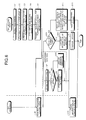
FIG. 6 is a flowchart of a procedure of automatic ticket examination processing performed by the BAN access point when a passenger arrives at an entrance; -
FIG. 7 is a flowchart of a procedure of automatic ticket examination processing performed by the BAN access point when a passenger arrives at an exit; -
FIG. 8 is a schematic of automatic ticket examining apparatuses each including an adaptive array antenna on a side surface thereof; -
FIG. 9 is a schematic of a beam pattern emitted from the adaptive array antenna toward an entrance direction; -
FIG. 10 is a schematic of a beam pattern emitted from the adaptive array antenna toward an exit direction; -
FIGS. 11A and 11B are schematics of automatic ticket examining apparatuses including no passenger detection sensor; and -
FIG. 12 is a flowchart of a procedure of a passenger detection process using no passenger detection sensor. - Exemplary embodiments of a ticket examining apparatus and a ticket examining method according to the present invention are described in detail below with reference to the accompanying drawings.
- The following describes an overview of an automatic ticket examination according to an embodiment of the present invention. In the automatic ticket examination according to the present embodiment, a portable telephone and a body area network (BAN) access point are employed. The portable telephone includes a built-in BAN terminal which includes a BAN communication device and an electronic money card. The BAN access point is installed in a gate. Because the BAN terminal is built in the portable telephone, a passenger need not use any special device for ticket examination.
- When a passenger arrives at the gate, very short distance wireless communication is automatically performed between the BAN terminal and the BAN access point. By performing wireless communication using a BAN, interference between gates is prevented. Further, the wireless communication using the BAN can lower the amount of electric power necessary for communication and reduce the risk of data leakage from the electronic money card.
- The BAN access point includes two passenger detection sensors and an adaptive array antenna. Two passenger detection sensors are respectively provided at the ends of the gate, and the adaptive array antenna is provided either on the ground at a center part of the gate or on one side surface of the gate. The adaptive array antenna emits a beam pattern toward the direction where the passenger arrives so as to access the information on the electronic money card.
- A passenger arrives either from the outside of a station (entrance side) or the inside of the station (exit side). Thus, the adaptive array antenna switches the beam pattern based on the position of the passenger at the gate. Arrival of the passenger is detected by either of the passenger detection sensors.
- When a passenger arrives at the entrance of the station, the BAN access point checks whether the balance on the electronic money card is sufficient for the minimum fare, by performing wireless communication using the BAN. Because the passenger moves inside the gate, the BAN access point switches the beam pattern of the adaptive array antenna from the entrance direction to the central direction to provide good communication, as necessary.
- When a passenger arrives at the exit of the station, the BAN access point calculates the fare from the boarding station to the alighting station, and deducts the calculated fare from the electronic money card when the electronic money card holds sufficient amount. To ensure the security, information on the electronic money card is encrypted at the portable telephone and decrypted at the BAN access point. Such encryption is particularly important when a credit card number and the like is transmitted from the portable telephone to the BAN access point. At the exit as well as the entrance, the beam pattern of adaptive array antenna is switched from the exit direction to the central direction, as necessary.
- The following describes a structure of an automatic ticket examining apparatus having a function of the BAN access point.
FIG. 1 is a schematic of automatic ticket examining apparatuses each including a BAN access point according to the present embodiment. InFIG. 1 , two automatic ticket examining apparatuses are provided next to each other. - As depicted in
FIG. 1 , in the automatic ticket examining apparatus according to the present embodiment, anadaptive array antenna 1 is provided on the ground at a central part of each gate. Theadaptive array antenna 1 emits abeam pattern 3 toward the direction where a passenger arrives. Because theadaptive array antenna 1 is provided on the ground, thebeam pattern 3 is emitted toward the ceiling. This prevents the radio wave from reaching a neighboring gate, i.e., prevents interference between gates. Side surfaces of an automatic ticket examining apparatusmain body 4 are made of metal, and also prevent the radio wave from reaching a neighboring gate. - By providing the
adaptive array antenna 1 on the ground, the distance between a portable telephone and a BAN access point can be made short compared with providing theadaptive array antenna 1 on the ceiling. This enables to suppress the electric power necessary for the communication. Considering that the portable telephone operates by battery, suppressing the electric power is important. Moreover, by shortening the distance between the portable telephone and the BAN access point, the risk of information leakage can be lowered. - To detect arrival of a passenger, a
passenger detection sensor 2 and apassenger detection sensor 7 are provided at the entrance and the exit of each gate, respectively. When no passenger is detected,entrance doors 6 andexit doors 5 are both kept closed. -
FIG. 2 is a schematic of thebeam pattern 3 emitted from theadaptive array antenna 1 toward the entrance direction.FIG. 3 is a schematic of thebeam pattern 3 emitted from theadaptive array antenna 1 toward the exit direction. As depicted inFIG. 2 , when apassenger 9 carrying aportable telephone 8 arrives at the entrance, thepassenger detection sensor 2 detects the passenger, and then theadaptive array antenna 1 provided onground 10 emits thebeam pattern 3 toward the entrance direction. When thepassenger 9 moves toward the exit inside the gate, theadaptive array antenna 1 switches the emission direction of thebeam pattern 3 toward the central direction. - On the other hand, as depicted in
FIG. 3 , when thepassenger 9 carrying theportable telephone 8 arrives at the exit, thepassenger detection sensor 7 detects the passenger, and then theadaptive array antenna 1 provided on theground 10 emits thebeam pattern 3 toward the exit direction. When thepassenger 9 moves toward the entrance inside the gate, theadaptive array antenna 1 switches the emission direction of thebeam pattern 3 toward the central direction. - In this way, the
adaptive array antenna 1 switches the emission direction of thebeam pattern 3 from the entrance direction or the exit direction toward the central direction according to the movement of thepassenger 9. Thus, good communication is maintained between the BAN terminal of theportable telephone 8 and the BAN access point. - The following describes a functional configuration of the BAN access point.
FIG. 4 is a functional block diagram of the BAN access point. As depicted inFIG. 4 , aBAN access point 20 includes awireless communication unit 11, an emissiondirection switching unit 12, apassenger detecting unit 13, an entrance/exitdoor controlling unit 14, adecryption unit 15, afare processing unit 16, adisplay unit 17, and a controllingunit 18. - The
wireless communication unit 11 is a processing unit that performs wireless communication with the BAN terminal of theportable telephone 8, using theadaptive array antenna 1 and the BAN. Thewireless communication unit 11 emits thebeam pattern 3 toward the entrance direction, the exit direction, or the central direction. Moreover, thewireless communication unit 11 estimates a received signal strength indication (RSSI) level of a signal received from the BAN terminal, and transmits the estimated result to the emissiondirection switching unit 12. - The emission
direction switching unit 12 is a processing unit that switches the direction of thebeam pattern 3 to be emitted from thewireless communication unit 11, toward the entrance direction, the exit direction, or the central direction. The emissiondirection switching unit 12 switches the emission direction of thebeam pattern 3, depending on which of thepassenger detection sensors wireless communication unit 11 from the BAN terminal. The emissiondirection switching unit 12 switches the emission direction of thebeam pattern 3, so that good communication is performed with the BAN terminal, using a single antenna. - The
passenger detecting unit 13 is a processing unit that detects arrival of a passenger using thepassenger detection sensors door controlling unit 14 is a processing unit that controls opening and closing of theentrance doors 6 and theexit doors 5. - The
decryption unit 15 is a processing unit that decrypts the information on the electronic money card encrypted and transmitted from the BAN terminal. Thedecryption unit 15 transmits an encryption code necessary for encryption to the BAN terminal. - The
fare processing unit 16 is a processing unit that performs fare processing. Thefare processing unit 16 checks the balance transmitted from the BAN terminal, deducts the fare from the balance, and transmits the remaining balance after deduction of the fare to the BAN communication device. Thefare processing unit 16 instructs thedisplay unit 17 to display a message, such as the remaining balance after deduction of the fare or an error message. Thedisplay unit 17 is a display that displays a message to the passenger. - The controlling
unit 18 is a processing unit that controls the entireBAN access point 20. Specifically, by shifting the control among functioning units or receiving and transmitting data, the controllingunit 18 enables theBAN access point 20 to function as one device. - The following describes a functional configuration of the BAN terminal.
FIG. 5 is a functional block diagram of the BAN terminal. As depicted inFIG. 5 , a BAN terminal 80 includes a wireless communication unit 81, an electronicmoney card unit 82, adata storage unit 83, anencryption unit 84, and a controllingunit 85. - The wireless communication unit 81 is a processing unit that wirelessly communicates with the
BAN access point 20 using the BAN. The electronicmoney card unit 82 is a storage unit that stores therein information such as the balance of electronic money. - The
data storage unit 83 is a storage unit used by the controllingunit 85 to temporally store data. Theencryption unit 84 is a processing unit that encrypts, when information on an electronic money card is transmitted to theBAN access point 20, the information on the electronic money card using an encryption code transmitted from theBAN access point 20. - The controlling
unit 85 is a processing unit that controls the entire BAN terminal 80. Specifically, the controllingunit 85 shifts the control among functional units or receives and transmits data based on the signal received by the wireless communication unit 81 from theBAN access point 20. In this way, the controllingunit 85 enables the BAN terminal 80 to function as one device. - The following describes a procedure of automatic ticket examination processing performed by the
BAN access point 20 when the passenger arrives at the entrance.FIG. 6 is a flowchart of a procedure of automatic ticket examination processing performed by theBAN access point 20 when a passenger arrives at the entrance. - As depicted in
FIG. 6 , in the automatic ticket examination processing, when thepassenger detecting unit 13 detects a passenger with the passenger detection sensor 2 (Step S1), theBAN access point 20 proceeds to an operation mode from a standby mode (Step S2). When no passenger is detected, theBAN access point 20 remains in the standby mode for saving electric power. - While the emission
direction switching unit 12 creates thebeam pattern 3 toward the entrance direction (Step S3), the entrance/exitdoor controlling unit 14 opens theentrance doors 6 and closes theexit doors 5 so that the passenger may go through the gate path during ticket examination processing (Step S4). Thewireless communication unit 11 emits thebeam pattern 3 toward the entrance direction and transmits a request signal for reading out payment information (Step S5). - In response to the request signal for reading out payment information, the BAN terminal 80 reads out the balance information from the electronic
money card unit 82, and transmits a signal to the BAN access point 20 (Step S6). Thewireless communication unit 11 of theBAN access point 20 receives the signal from the BAN terminal 80 and estimates the RSSI level (Step S7). - The emission
direction switching unit 12 determines whether the RSSI level is greater than a threshold (Step S8). If the RSSI level is greater than the threshold, the passenger exists within the current range of thebeam pattern 3, and therefore the emissiondirection switching unit 12 keeps the emission direction of the beam pattern 3 (Step S9). On the contrary, if the RSSI level is less than the threshold, the emissiondirection switching unit 12 determines that the passenger has moved out from the current range of thebeam pattern 3, so as to switch the emission direction of thebeam pattern 3 to the central direction (Step S10). - The
fare processing unit 16 of theBAN access point 20 receives the balance information from thewireless communication unit 11, and determines whether the balance is equal to or more than the minimum fare (Step S11). If the balance is equal to or more than the minimum fare, the passenger can board. Thus, thefare processing unit 16 transmits information of the boarding station to the BAN terminal 80 so that the fare can be calculated at the alighting station (Step S12). The entrance/exitdoor controlling unit 14 opens theexit doors 5 so that the passenger can enter the station (Step S13). - On the contrary, if the balance is not equal to or more than the minimum fare, the passenger cannot board. Because the balance is not sufficient, the
display unit 17 displays a message requesting to charge the electronic money card (Step S14). The entrance/exitdoor controlling unit 14 keeps theexit doors 5 closed so that the passenger cannot enter the station (Step S15). In the BAN terminal 80, upon receiving the information of the boarding station via the wireless communication unit 81, the controllingunit 85 updates the electronic money card with the received information of the boarding station (Step S16). - In this way, the
BAN access point 20 performs wireless communication with the BAN terminal 80 while controlling switching of thebeam pattern 3. This enables the automatic ticket examination processing at the time of boarding under a good communication environment. - The following describes a procedure of automatic ticket examination processing performed by the
BAN access point 20 when a passenger arrives at the exit.FIG. 7 is a flowchart of a procedure of automatic ticket examination processing performed by theBAN access point 20 when a passenger arrives at the exit. - As illustrated in
FIG. 7 , in the automatic ticket examination processing, when thepassenger detecting unit 13 detects a passenger with the passenger detection sensor 7 (Step S18), theBAN access point 20 proceeds to an operation mode from a standby mode (Step S19). - While the emission
direction switching unit 12 creates thebeam pattern 3 toward the exit direction (Step S20), the entrance/exitdoor controlling unit 14 opens theexit doors 5 and closes theentrance doors 6 so that the passenger may go through the gate path during ticket examination processing (Step S21). Thewireless communication unit 11 emits thebeam pattern 3 toward the exit direction and transmits a request signal for reading out payment information (Step S22). - In response to the request signal for reading out the payment information, the BAN terminal 80 reads out the information of the balance and the boarding station from the electronic
money card unit 82, and transmits a signal to the BAN access point 20 (Step S23). Thewireless communication unit 11 of theBAN access point 20 receives the signal from the BAN terminal 80 and estimates the RSSI level (Step S24). - The emission
direction switching unit 12 determines whether the RSSI level is greater than a threshold (Step S25). If the RSSI level is greater than the threshold, the passenger exists within the current range of thebeam pattern 3, and therefore the emissiondirection switching unit 12 keeps the emission direction of the beam pattern 3 (Step S26). On the contrary, if the RSSI level is less than the threshold, the emissiondirection switching unit 12 determines that the passenger has moved out from the current range of thebeam pattern 3, so as to switch the emission direction of the beam pattern 3 (Step S27). - The
fare processing unit 16 of theBAN access point 20 receives the information of the balance and the boarding station from thewireless communication unit 11, calculates a fare (Step S28), and determines whether the balance is equal to or more than the minimum fare (Step S29). If the balance is equal to or more than the minimum fare, payment is possible. Thus, thefare processing unit 16 generates an encryption code for encrypting the information (e.g., electronic money information) on the electronic money card (Step S30) and transmits the code to the BAN terminal 80. - The
encryption unit 84 of the BAN terminal 80 encrypts the electronic money information using the encryption code (Step S33), and transmits the information to theBAN access point 20. Thedecryption unit 15 of theBAN access point 20 decrypts the electronic money information (Step S34), adjusts the fare (Step S35), and transmits a payment result to the BAN terminal 80. The controllingunit 85 of the BAN terminal 80 updates the balance of the electronic money card unit 82 (Step S37). The entrance/exitdoor controlling unit 14 of theBAN access point 20 opens theentrance doors 6 so that the passenger can exit the station (Step S36). - On the contrary, if the balance is not equal to or more than the fare, the balance is not sufficient for the fare. Due to the insufficient balance, the
display unit 17 displays a message requesting to charge the electronic money card (Step S31). The entrance/exitdoor controlling unit 14 keeps theentrance doors 6 closed so that the passenger cannot exit the station (Step S32). - In this way, the
BAN access point 20 performs wireless communication with the BAN terminal 80 while controlling switching of thebeam pattern 3. This enables the automatic ticket examination processing at the time of alighting under a good communication environment. - As described above, according to the present embodiment, the
adaptive array antenna 1 is provided on the ground at a center part of a gate and wireless communication is performed using the BAN. This prevents the interference between gates, realizing wireless communication with less electric power. - According to the present embodiment, the emission
direction switching unit 12 switches the direction of thebeam pattern 3 to be emitted from theadaptive array antenna 1 to the entrance direction, the central direction, or the exit direction, according to where the passenger arrives or the movement of the passenger. Accordingly, the automatic ticket examination which requires the passenger only to pass through the gate is realized with a single antenna. - According to the embodiment, the
adaptive array antenna 1 is provided on the ground at a center part of a gate. Theadaptive array antenna 1 can be provided on a side surface of the automatic ticket examining apparatus.FIG. 8 is a schematic of automatic ticket examining apparatuses each including theadaptive array antenna 1 on a side surface thereof.FIG. 9 is a schematic of thebeam pattern 3 emitted from theadaptive array antenna 1 toward the entrance direction.FIG. 10 is a schematic of thebeam pattern 3 emitted from theadaptive array antenna 1 toward the exit direction. - As illustrated in
FIGS. 8 to 10 , the automatic ticket examining apparatus can emit thebeam pattern 3 from the side surface thereof, by using theadaptive array antenna 1 provided on the side surface and by switching the emission direction to the entrance direction, the central direction, or the exit direction. As such, providing theadaptive array antenna 1 on the side surface of the automatic ticket examining apparatus also prevents the interference between gates, realizing wireless communication with less electric power. - The above describes detection of a passenger using the
passenger detection sensors passenger detection sensors FIGS. 11A and 11B are schematics of automatic ticket examining apparatuses including no passenger detection sensor.FIG. 11A depicts theadaptive array antennas 1 each provided on the ground at each gate, andFIG. 11B depicts theadaptive array antennas 1 provided on one side surfaces of the automatic ticket examining apparatusmain body 4. -
FIG. 12 is a flowchart of a procedure of a passenger detection process using no passenger detection sensor. As depicted inFIG. 12 , when using no passenger detection sensor, theBAN access point 20 transmits a beacon to the entrance direction by emitting a beam (Step S39), and determines whether a response is given in a certain period of time (Step S40). - If a response is given, the
BAN access point 20 determines that the passenger has arrived at the entrance (Step S41), and the system control goes to Step S2 ofFIG. 6 . On the contrary, if no response is given, theBAN access point 20 transmits a beacon to the exit direction by emitting a beam (Step S42), and determines whether a response is given in a certain period of time (Step S43). - If a response is given, the
BAN access point 20 determines that the passenger has arrived at the exit (Step S44), and the system control goes to Step S19 ofFIG. 7 . If no response is given, no passenger has arrived at the entrance or the exit. Thus, the system control goes back to Step S39 and continues the process for detecting the arrival of a passenger. - In this way, the
BAN access point 20 can detect the arrival of a passenger, without using passenger detection sensors, by transmitting a beacon to the entrance direction and the exit direction and detecting the response from the BAN terminal 80. - In the present embodiment, the emission direction of the
beam pattern 3 is switched from the entrance direction or the exit direction to the central direction at one time according to the movement of a passenger inside the gate. Embodiments of the present invention are not limited to this, and thebeam pattern 3 may be switched from the entrance direction or the exit direction to the central direction through several steps. - The present embodiment describes the automatic ticket examination at railway stations. Embodiments of the present invention are not limited to this, and are also applicable to a gate that permits a user to enter a specific region or place, or to exit from a specific region or place. Specifically, embodiments of the present invention are applicable to ticket examining apparatuses provided at bus gates, theaters, concert halls, stadiums, gyms, zoos, and offices.
- The information necessary for entering and exiting, however, differs depending on the conditions where the ticket examining apparatuses are provided. For example, information on electronic tickets reserved in advance is required at concert halls, theaters, and stadiums. Information on employee ID numbers is required at offices.
- According to one embodiment of the present invention, plural antennas are not required. This provides an advantage of reducing cost of the ticket examining apparatus.
- Constituting elements of embodiments of the present invention, representations, or a given combination of such constituting elements may be applied to a method, an apparatus, a system, a computer program, a recording medium, a data structure, and the like. Such application is effective for solving the problems described earlier.
- All examples and conditional language recited herein are intended for pedagogical purposes to aid the reader in understanding the invention and the concepts contributed by the inventor to furthering the art, and are to be construed as being without limitation to such specifically recited examples and conditions, nor does the organization of such examples in the specification relate to a showing of the superiority and inferiority of embodiments of the invention. Although the embodiments of the present inventions have been described in detail, it should be understood that the various changes, substitutions, and alterations could be made hereto without departing from the scope of the invention.
- In any of the above aspects, the various features may be implemented in hardware, or as software modules running on one or more processors. Features of one aspect may be applied to any of the other aspects.
- The invention also provides a computer program product for carrying out any of the methods described herein, and a computer readable medium having stored thereon a program for carrying out any of the methods described herein. A computer program embodying the invention may be stored on a computer-readable medium, or it could, for example, be in the form of a signal such as a downloadable data signal provided from an Internet website, or it could be in any other form.
Claims (8)
- An apparatus for examining a ticket, the apparatus comprising:a transmitting and receiving direction switching unit (12) that switches a transmitting and receiving direction of a signal to be transmitted and received by an antenna (1), provided within a gate, either toward an entrance direction or an exit direction where a user (9) arrives; anda pass permission determining unit that determines whether to permit the user to pass through the gate, by wirelessly communicating with a portable apparatus (8) of the user using a signal transmitted and received by the antenna (1) and switchably directed by the transmitting and receiving direction switching unit (12) toward one of the entrance direction and the exit direction.
- The apparatus according to claim 1, wherein the transmitting and receiving direction switching unit (12) switches, according to movement of the user (9) within the gate, a transmitting and receiving direction of the signal from one of the entrance direction and the exit direction to a movement direction of the user.
- The apparatus according to claim 1 or 2, wherein the transmitting and receiving direction switching unit (12) switches the transmitting and receiving direction from one of the entrance direction and the exit direction to a movement direction of the user (9), when a strength of a received signal is equal to or less than a predetermined threshold.
- The apparatus according to any of claims 1 to 3, wherein the transmitting and receiving direction switching unit (12) switches the transmitting and receiving direction from one of the entrance direction and the exit direction to a central direction of the gate, when a strength of a received signal is equal to or less than a predetermined threshold.
- The apparatus according to any one of claims 1 to 4, further comprising
a user detecting unit that detects arrival of the user at one of an entrance and an exit, by detecting the portable apparatus (8) using a beacon, and
the transmitting and receiving direction switching unit (12) switches the transmitting and receiving direction to one of the entrance direction and the exit direction where the arrival of the user (9) is detected by the user detecting unit. - The apparatus according to any one of claims 1 to 5, wherein a body area network (BAN) is used to wirelessly communicate with the portable apparatus (8).
- The apparatus according to any one of claims 1 to 6, wherein the antenna (1) is provided on ground in the gate.
- A method for examining a ticket, the method comprising:switching a transmitting and receiving direction of a signal to be transmitted and received by an antenna (1), provided within a gate, toward one of an entrance direction and an exit direction where a user (9) arrives; anddetermining whether to permit the user to pass through the gate, by wirelessly communicating with a portable apparatus (8) of the user using a signal transmitted and received by the antenna (1) and switchably directed toward one of the entrance direction and the exit direction in the switching.
Applications Claiming Priority (1)
| Application Number | Priority Date | Filing Date | Title |
|---|---|---|---|
| JP2008163792A JP2010003271A (en) | 2008-06-23 | 2008-06-23 | Ticket gate apparatus and ticket gate method |
Publications (2)
| Publication Number | Publication Date |
|---|---|
| EP2138981A2 true EP2138981A2 (en) | 2009-12-30 |
| EP2138981A3 EP2138981A3 (en) | 2010-04-21 |
Family
ID=40723124
Family Applications (1)
| Application Number | Title | Priority Date | Filing Date |
|---|---|---|---|
| EP20090156440 Withdrawn EP2138981A3 (en) | 2008-06-23 | 2009-03-27 | Ticket examining apparatus and ticket examining method |
Country Status (3)
| Country | Link |
|---|---|
| US (1) | US20090314833A1 (en) |
| EP (1) | EP2138981A3 (en) |
| JP (1) | JP2010003271A (en) |
Cited By (2)
| Publication number | Priority date | Publication date | Assignee | Title |
|---|---|---|---|---|
| WO2016205617A1 (en) * | 2015-06-19 | 2016-12-22 | Cubic Corporation | Rfid for fare collection |
| US11049347B2 (en) | 2017-09-06 | 2021-06-29 | Sony Corporation | Gate apparatus and method in gate apparatus |
Families Citing this family (12)
| Publication number | Priority date | Publication date | Assignee | Title |
|---|---|---|---|---|
| CN102081811A (en) * | 2010-11-17 | 2011-06-01 | 永泰软件有限公司 | Control system of self-service clearance equipment |
| US11055686B2 (en) * | 2012-08-08 | 2021-07-06 | E2Interactive, Inc. | S/M for providing, reloading, and redeeming stored value cards used in transit applications |
| US9805529B2 (en) * | 2012-10-12 | 2017-10-31 | United Parcel Service Of America, Inc. | Concepts for asset identification |
| FR3013493B1 (en) | 2013-11-20 | 2016-01-01 | Thales Sa | SYSTEM FOR CONTROLLING ACCESS TO A RESERVED AREA WITH A LOGE MODULE UNDER THE PASSAGE |
| BR112017016648A2 (en) * | 2015-02-02 | 2018-07-31 | Tma Capital Australia Pty Ltd | computer system, method and program for an access control system |
| BR112019001784A2 (en) | 2016-07-29 | 2019-07-09 | Tma Capital Australia Pty Ltd | computer system, method and program for a monitoring system |
| CN109191619B (en) * | 2018-07-13 | 2021-01-26 | 上海建工集团股份有限公司 | RFID-based construction site informatization access control system and setting and using method thereof |
| IT201900006024A1 (en) * | 2019-04-18 | 2020-10-18 | Blueticketing Srl | Access control device. |
| JP7253443B2 (en) * | 2019-05-16 | 2023-04-06 | マスプロ電工株式会社 | tag reading system |
| CN113379012B (en) * | 2021-05-31 | 2022-06-21 | 长沙中天电子设计开发有限公司 | Method, system and equipment for judging advancing state of personnel in school door area |
| US20220391882A1 (en) * | 2021-06-08 | 2022-12-08 | Phillip Graves | Systems and methods for providing, reloading, and redeeming stored value cards used in transit applications |
| KR102512353B1 (en) * | 2022-07-04 | 2023-03-22 | 삼원에프에이 (주) | Operation method and system of ticket auto-collecting/counting apparatus for real-time demand response |
Citations (1)
| Publication number | Priority date | Publication date | Assignee | Title |
|---|---|---|---|---|
| JP2005069861A (en) | 2003-08-25 | 2005-03-17 | Nec Tokin Corp | Radio communication equipment |
Family Cites Families (15)
| Publication number | Priority date | Publication date | Assignee | Title |
|---|---|---|---|---|
| JPS62128358A (en) * | 1985-11-29 | 1987-06-10 | Toshiba Corp | Admission management system |
| JPH07105329A (en) * | 1993-09-30 | 1995-04-21 | Omron Corp | Non-contact medium processing device |
| JP3526928B2 (en) * | 1994-11-15 | 2004-05-17 | 株式会社ルネサスLsiデザイン | Non-contact IC card system |
| JP4502291B2 (en) * | 2000-04-17 | 2010-07-14 | 国立大学法人横浜国立大学 | Mobile communication system and base station used in this system |
| JP4789321B2 (en) * | 2000-12-27 | 2011-10-12 | キヤノン株式会社 | Wireless communication system, access control apparatus, wireless communication apparatus, control method of wireless communication system, control method of access control apparatus, and control method of wireless communication apparatus |
| EP1320080A1 (en) * | 2001-12-13 | 2003-06-18 | EM Microelectronic-Marin SA | System and method for detecting the passage of a person or an object through an entrance-exit area in a confined space |
| JP2003196692A (en) * | 2001-12-25 | 2003-07-11 | Mitsubishi Electric Corp | Automatic toll collection system |
| FR2849519B1 (en) * | 2002-12-31 | 2005-03-11 | Automatic Systems | AUTOMATED DOOR FOR ALLOWING OR PROHIBITING ACCESS TO A SPACE OR A TRANSPORT VEHICLE, IN PARTICULAR A BOARDING ROOM OR AN AIRCRAFT |
| US7331522B2 (en) * | 2003-08-07 | 2008-02-19 | Cubic Corporation | Virtual gate system |
| JP4618483B2 (en) * | 2004-06-01 | 2011-01-26 | ブラザー工業株式会社 | Interrogator for RFID tag communication system and RFID tag communication system |
| JP4239033B2 (en) * | 2004-06-15 | 2009-03-18 | ブラザー工業株式会社 | Interrogator for RFID tag communication system |
| US20060044112A1 (en) * | 2004-08-31 | 2006-03-02 | Raj Bridgelall | Wearable RFID reader and system |
| JP2006268695A (en) * | 2005-03-25 | 2006-10-05 | Toshiba Tec Corp | Wireless tag communication control device |
| JP4539551B2 (en) * | 2005-12-20 | 2010-09-08 | ソニー株式会社 | Information processing system and method, information processing apparatus and method, and program |
| US7568617B2 (en) * | 2006-12-07 | 2009-08-04 | Specialty Acquirer Llc | Learning fare collection system for mass transit |
-
2008
- 2008-06-23 JP JP2008163792A patent/JP2010003271A/en not_active Withdrawn
-
2009
- 2009-03-26 US US12/382,911 patent/US20090314833A1/en not_active Abandoned
- 2009-03-27 EP EP20090156440 patent/EP2138981A3/en not_active Withdrawn
Patent Citations (1)
| Publication number | Priority date | Publication date | Assignee | Title |
|---|---|---|---|---|
| JP2005069861A (en) | 2003-08-25 | 2005-03-17 | Nec Tokin Corp | Radio communication equipment |
Cited By (3)
| Publication number | Priority date | Publication date | Assignee | Title |
|---|---|---|---|---|
| WO2016205617A1 (en) * | 2015-06-19 | 2016-12-22 | Cubic Corporation | Rfid for fare collection |
| US10282920B2 (en) | 2015-06-19 | 2019-05-07 | Cubic Corporation | RFID for fare collection |
| US11049347B2 (en) | 2017-09-06 | 2021-06-29 | Sony Corporation | Gate apparatus and method in gate apparatus |
Also Published As
| Publication number | Publication date |
|---|---|
| EP2138981A3 (en) | 2010-04-21 |
| US20090314833A1 (en) | 2009-12-24 |
| JP2010003271A (en) | 2010-01-07 |
Similar Documents
| Publication | Publication Date | Title |
|---|---|---|
| EP2138981A2 (en) | Ticket examining apparatus and ticket examining method | |
| US11968592B2 (en) | Position determination system, position determination apparatus, position determination method, position determination program, and computer-readable storage medium and storage device | |
| US10096181B2 (en) | Hands-free fare gate operation | |
| US9972149B2 (en) | Vision-based fare collection | |
| US10282920B2 (en) | RFID for fare collection | |
| US20050241003A1 (en) | Cellular telephone based electronic access control system | |
| US20210141890A1 (en) | Systems and methods for location-based automated authentication | |
| US20160300413A1 (en) | Radio frequency patch antenna and system for permitting secure access to a restricted area | |
| JP6358135B2 (en) | Traffic management system, portable device, gate device, entry notification program, traffic management program, and traffic management method | |
| JP2006161390A (en) | User authentication device and entrance / exit management device | |
| JP2018206355A (en) | Mobile device and reader for facilitating transactions | |
| US20180091641A1 (en) | Repeater for frictionless access control system | |
| JP2007080248A (en) | How to restrict access to areas where people can go in and out, especially spaces closed by doors | |
| WO2018047346A1 (en) | Mobile terminal, power consumption control program, and power consumption control method | |
| JP2006072672A (en) | Entrance / exit management system | |
| JP6592937B2 (en) | Authentication system, authentication control device program | |
| KR20150076528A (en) | Wireless communication terminal, contaceless payment system using the terminal and payment method thereof | |
| KR20150076527A (en) | Wireless communication terminal, contaceless payment system using the terminal and payment method thereof | |
| JP5040410B2 (en) | Authentication information presentation apparatus, program, and portable device | |
| JP5454616B2 (en) | Authentication information presentation apparatus, program, and portable device | |
| JP2019175253A (en) | Authentication system and authentication device | |
| JP4744946B2 (en) | Automatic ticket gate | |
| KR102817347B1 (en) | Bus automatic payment system and method using beacons | |
| JP2019175252A (en) | Authentication system and portable terminal | |
| Tsumachi et al. | Demonstration experiment of a 5g touchless gate utilizing directional beam and mobile edge computing |
Legal Events
| Date | Code | Title | Description |
|---|---|---|---|
| PUAI | Public reference made under article 153(3) epc to a published international application that has entered the european phase |
Free format text: ORIGINAL CODE: 0009012 |
|
| AK | Designated contracting states |
Kind code of ref document: A2 Designated state(s): AT BE BG CH CY CZ DE DK EE ES FI FR GB GR HR HU IE IS IT LI LT LU LV MC MK MT NL NO PL PT RO SE SI SK TR |
|
| AX | Request for extension of the european patent |
Extension state: AL BA RS |
|
| PUAL | Search report despatched |
Free format text: ORIGINAL CODE: 0009013 |
|
| AK | Designated contracting states |
Kind code of ref document: A3 Designated state(s): AT BE BG CH CY CZ DE DK EE ES FI FR GB GR HR HU IE IS IT LI LT LU LV MC MK MT NL NO PL PT RO SE SI SK TR |
|
| AX | Request for extension of the european patent |
Extension state: AL BA RS |
|
| RIC1 | Information provided on ipc code assigned before grant |
Ipc: G01S 3/32 20060101ALI20100318BHEP Ipc: G07C 9/00 20060101ALI20100318BHEP Ipc: G07B 15/04 20060101ALI20100318BHEP Ipc: G07B 15/00 20060101ALI20100318BHEP Ipc: G07C 9/02 20060101AFI20090616BHEP |
|
| AKY | No designation fees paid | ||
| REG | Reference to a national code |
Ref country code: DE Ref legal event code: 8566 |
|
| STAA | Information on the status of an ep patent application or granted ep patent |
Free format text: STATUS: THE APPLICATION IS DEEMED TO BE WITHDRAWN |
|
| 18D | Application deemed to be withdrawn |
Effective date: 20101022 |