EP2138872A1 - Photonic band-gap fiber - Google Patents
Photonic band-gap fiber Download PDFInfo
- Publication number
- EP2138872A1 EP2138872A1 EP07828438A EP07828438A EP2138872A1 EP 2138872 A1 EP2138872 A1 EP 2138872A1 EP 07828438 A EP07828438 A EP 07828438A EP 07828438 A EP07828438 A EP 07828438A EP 2138872 A1 EP2138872 A1 EP 2138872A1
- Authority
- EP
- European Patent Office
- Prior art keywords
- loss
- air holes
- pbgf
- hollow core
- wavelength
- Prior art date
- Legal status (The legal status is an assumption and is not a legal conclusion. Google has not performed a legal analysis and makes no representation as to the accuracy of the status listed.)
- Withdrawn
Links
Images


Classifications
-
- G—PHYSICS
- G02—OPTICS
- G02B—OPTICAL ELEMENTS, SYSTEMS OR APPARATUS
- G02B6/00—Light guides; Structural details of arrangements comprising light guides and other optical elements, e.g. couplings
- G02B6/02—Optical fibres with cladding with or without a coating
- G02B6/02295—Microstructured optical fibre
- G02B6/02314—Plurality of longitudinal structures extending along optical fibre axis, e.g. holes
- G02B6/02342—Plurality of longitudinal structures extending along optical fibre axis, e.g. holes characterised by cladding features, i.e. light confining region
- G02B6/02347—Longitudinal structures arranged to form a regular periodic lattice, e.g. triangular, square, honeycomb unit cell repeated throughout cladding
-
- G—PHYSICS
- G02—OPTICS
- G02B—OPTICAL ELEMENTS, SYSTEMS OR APPARATUS
- G02B6/00—Light guides; Structural details of arrangements comprising light guides and other optical elements, e.g. couplings
- G02B6/02—Optical fibres with cladding with or without a coating
- G02B6/02295—Microstructured optical fibre
- G02B6/02314—Plurality of longitudinal structures extending along optical fibre axis, e.g. holes
- G02B6/02319—Plurality of longitudinal structures extending along optical fibre axis, e.g. holes characterised by core or core-cladding interface features
- G02B6/02323—Core having lower refractive index than cladding, e.g. photonic band gap guiding
- G02B6/02328—Hollow or gas filled core
Definitions
- the present invention relates to a photonic bandgap fiber including a hollow core for propagating a light formed along a center axis of a cladding region and air holes periodically arranged around the hollow core.
- a light in a wavelength range from ultraviolet to visible light is used in a wide range of fields, such as medical care, biotechnology, sensing, measurement, optical recording, and material machining.
- an optical waveguide for guiding a light in the ultraviolet range over a relatively long distance is used. More specifically, in facilities such as a nuclear reactor in which radiation is generated, it is a subject of great importance to measure and control intensity of radiation to ensure safety of people and the facilities. Particularly, in the case of performing a regular inspection of the reactor, for example, which necessitates a person to actually go into the reactor to perform an inspection work, it is necessary to measure the intensity of radiation in advance to ensure safety.
- a scintillator that converts the radiation into a fluorescence is installed, the fluorescence emitted by the scintillator is guided to a safe location using an optical waveguide, and the amount of a guided fluorescence is measured to obtain the intensity of radiation.
- the wavelength of fluorescence emitted by the scintillator is about 0.4 ⁇ m to 0.55 ⁇ m.
- the optical waveguide to guide the light in this wavelength range over a relatively long distance for example, about 100 m, a plastic optical fiber or a silica-based optical fiber widely used for the field of optical communication is used.
- the photonic bandgap fiber includes a hollow core for propagating a light formed along the center axis of the fiber and air holes periodically arranged around the hollow core.
- Nonpatent Literature 1 P. J. Roberts, et al., "Ultimate low loss of hollow-core photonic crystal fibres” Optics Express, v. 13, no. 1, pp. 236-244 (2004 ).
- Nonpatent Literature 2 G. Humbert, et al., "Hollow core photonic crystal fibers for beam delivery” Optics Express, v. 12, no. 8, pp. 1477-1484 (2004 ).
- a current silica-based optical fiber has a high transmission loss of 30 dB/km or more at, for example, a wavelength of 0.4 ⁇ m.
- the plastic optical fiber has an even higher transmission loss, and therefore there is a problem of limitation in an optical waveguide distance.
- the present invention has been achieved to solve the above problems, and it is an object of the present invention to provide a photonic bandgap fiber capable of guiding a light in the ultraviolet to visible range with low loss.
- a photonic bandgap fiber according to the present invention includes a cladding region made of silica glass that includes a hollow core formed along a center axis of the cladding region, through which a light propagates and air holes forming a triangular lattice arranged around the hollow core.
- the air holes have ⁇ of 2.1 ⁇ m or less, where ⁇ is a lattice constant of the triangular lattice. Confinement loss in a predetermined wavelength range including a center wavelength of a photonic bandgap is lower than scattering loss.
- the photonic bandgap fiber according to the present invention has the confinement loss of 10 dB/km or less.
- the photonic bandgap fiber according to the present invention has the center wavelength of 0.4 ⁇ m, the lattice constant ⁇ of 1.05 ⁇ m or less, d/ ⁇ of 0.97 or less, where d is a hole diameter of the air holes, the number of equilateral hexagonal layers formed by the air holes surrounding the hollow core of six or more, and a wavelength range in which the confinement loss of 10 dB/km or less is 20 nm or more.
- a photonic bandgap fiber capable of guiding a light in an ultraviolet to visible range with low loss.
- the photonic bandgap fiber is referred to as a PBGF.
- the ultraviolet to visible range indicates a wavelength of 0.2 ⁇ m to 0.8 ⁇ m.
- Fig. 1 is a schematic cross section and an enlarged center area of a PBGF according to an embodiment of the present invention.
- the PBGF 1 transmits a light having a wavelength of 0.4 ⁇ m with low loss.
- the PBGF 1 includes a hollow core 1b for propagating a light formed along the center axis of the PBGF 1 and a cladding region 1a formed around the hollow core 1b.
- the cladding region 1a is formed with air holes 1c periodically arranged in silica glass and the silica glass covering the periphery of the air holes 1c.
- the periphery of the cladding region 1a is provided with a coating (not shown) made of UV-curing resin or the like.
- the air holes 1c are arranged to form a triangular lattice.
- the diameter of the air holes 1c is d, and a lattice constant of the triangular lattice is ⁇ .
- the shape of the hollow core 1b is an equilateral hexagon whose vertexes are rounded with the size virtually equivalent to the size that is occupied by one of the air holes 1c and six surrounding air holes closest to the hole.
- the air holes 1c are arranged in a plurality of equilateral hexagonal layers surrounding the hollow core 1b, and in the present embodiment, the air holes 1c are arranged in a seven-layer structure.
- ⁇ is set to 1.05 ⁇ m, and d/ ⁇ is set to 0.97, and as a result, a bandgap with a center wavelength of 0.4 ⁇ m is formed, and confinement loss is 10 dB/km or less over a 40 nm-wavelength range including the wavelength of 0.4 ⁇ m.
- the PBGF 1 has the structure shown in Fig. 1 , majority of the light is confined within the hollow core 1b and propagates through the core. Consequently, the scattering loss due to the silica glass during propagation of light is as low as about 13 dB/km in the 40 nm-wavelength range, which means that the confinement loss is lower than the scattering loss.
- the PBGF 1 is low in transmission loss including the confinement loss, the scattering loss, and the absorption loss over the 40 nm-wavelength range including the wavelength of 0.4 ⁇ m, and thus the light in the wavelength range can be guided with low loss.
- Nonpatent Literature 1 the transmission loss of the PBGF is caused by scattering loss mainly on the surfaces of air holes, and it is theoretically and experimentally proved that the wavelength dependency of the scattering loss is proportional to 1/ ⁇ 3 , where ⁇ is the wavelength. Furthermore, a currently available PBGF realizes low transmission loss of 1.2 dB/km at a wavelength of 1.62 ⁇ m, however it is indicated that by optimizing the core structure, the transmission loss can be reduced to about 0.2 dB/km.
- the Rayleigh scattering loss is generated by the silica glass forming the core, and it is known that the Rayleigh scattering loss shows wavelength dependency of 1/ ⁇ 4 .
- Fig. 2 is a graph showing wavelength dependency of scattering loss in the PBGF and in the ordinary silica-based optical fiber.
- a line L1 indicates the scattering loss on the surfaces of the air holes of the PBGF, and a line L2 indicates the Rayleigh scattering loss in the silica-glass core of the ordinary silica-based optical fiber.
- the scattering loss at the wavelength of 1.62 ⁇ m is about 0.2 dB/km.
- values on the line L1 are lower than those on the line L2, which indicates a possibility that the transmission loss of the PBGF is lower than the transmission loss of the silica-based optical fiber.
- the optical loss is increased due to the absorption of ultraviolet accompanied by the electron transition.
- the influence of the absorption loss is significantly large.
- 99% or more of the guided light propagates through the hollow core in the case of the PBGF and the light propagating in the silica glass is as small as about 1%, it is considered that the influence of the absorption loss due to electron transition is considerably small.
- the optical fiber when used for the radiation measurement, it is predicted that there may occur a problem that when the optical fiber is used for a long time in an environment with the radiation, the radiation itself causes a defect in the silica glass and optical loss thereby increases.
- the PBGF in which light propagates through the hollow core, it is predicted that the increase in the optical loss due to such defect is small, and therefore it is thought that the PBGF has merits of lower loss compared with the ordinary silica-based optical fiber.
- the coating should be preferably made of silicon.
- the inventors of the present invention have focused their attention on that the PBGF has the possibility of guiding the light in the ultraviolet to visible range with lower loss for the above-mentioned reasons, and as a result of diligent research on this matter, the inventors have achieved the present invention.
- the PBGF according to the present embodiment is more specifically explained below with reference to a result of simulation using a finite element method (FEM).
- FEM finite element method
- a result of calculation of wavelength dependency of confinement loss of the PBGF is explained first for a PBGF having the same structure as that of the PBGF 1 shown in Fig. 1 , in which ⁇ is set to 1.05 ⁇ m, d/ ⁇ is set to 0.97, and the air holes are arranged in three layers.
- Fig. 3 is a schematic diagram of a field distribution (E x distribution) of a light within the cross section of the PBGF in the first calculation example.
- the lighter region indicates the higher intensity of the field.
- majority of the light is confined within the hollow core located at the center of the PBGF in the first calculation example, however a part of the light leaks from the hollow core.
- Fig. 4 is a graph showing wavelength dependency of confinement loss of the PBGF in the first calculation example. As shown in Fig. 4 , it is confirmed that by setting ⁇ to 1.05 ⁇ m and d/ ⁇ to 0.97 in the PBGF in the first calculation example, the confinement loss is minimized near the wavelength of 0.4 ⁇ m with a formation of a bandgap. However, because the PBGF in the first calculation example includes only three layers of the air holes, as shown in Fig. 3 , the light leaks from the hollow core, and the confinement loss within the bandgap is as high as 1000 dB/km or more.
- Fig. 5 is a schematic diagram of a field distribution (E x distribution) of a light within the cross section of the PBGF having seven layers of air holes in the fifth calculation example. As shown in Fig. 5 , majority of the light is confined within the hollow core located at the center of the PBGF in the fifth calculation example.
- Fig. 6 is a graph showing wavelength dependency of confinement loss of the PBGFs in the second to the fifth calculation examples.
- the confinement loss decreases as the number of layers of the air holes increases.
- the scattering loss of the PBGF at the wavelength of 0.4 ⁇ m is about 13 dB/km, and thus, if the confinement loss is 10 dB/km or less, it is considered that the value is acceptable compared to the scattering loss. Therefore, as shown in Fig.
- the confinement loss in the wavelength range including the center wavelength of the bandgap becomes 10 dB/km or less, which makes it possible to realize allowable confinement loss.
- the wavelength range in which the confinement loss is 10 dB/km or less is 25 nm when the number of layers is six, and is 40 nm when the number of layers is seven in the same manner as the PBGF according to the first embodiment. Furthermore, if the number of layers is seven, it is possible to realize extremely low confinement loss of about 0.1 dB/km.
- the effective area of the PBGFs in the second to the fifth calculation examples is about 3.5 ⁇ m 2 at the wavelength of 0.4 ⁇ m, which is almost constant regardless of the number of layers.
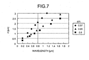
- Fig. 7 is a graph showing a relationship between the center wavelength of the bandgap and the value of ⁇ to obtain the center wavelength in a PBGF having the same structure as that of PBGF 1 shown in Fig. 1 , where d/ ⁇ is set to 0.97, 0.95, and 0.9.
- the center wavelength can be shorter than the visible light range, namely, 0.8 ⁇ m or less.
- d/ ⁇ should be preferably set to 0.97 or less because the thickness of the glass between the air holes is decreased.
- ⁇ needs to be 1.05 ⁇ m or less to obtain the center wavelength of the bandgap of 0.4 ⁇ m.
- the PBGF according to the present embodiment can be easily fabricated by using the well-known stack and draw method. More specifically, silica-glass capillary tubes for forming the air holes are arranged in a triangular lattice shape in a silica-glass jacket tube, and thereafter, one capillary tube located near the center axis of the jacket tube and six capillary tubes around the one capillary tube are removed, an equilateral hexagonal hollow portion is thereby formed as the hollow core, to prepare a preform, and then the preform is drawn to fabricate the PBGF.
- the photonic bandgap fiber according to the present invention is suitable for a waveguide for guiding a light in the ultraviolet to visible range, in a wide range of fields, such as medical care, biotechnology, sensing, measurement, optical recording, and material machining.
Landscapes
- Physics & Mathematics (AREA)
- General Physics & Mathematics (AREA)
- Optics & Photonics (AREA)
- Optical Fibers, Optical Fiber Cores, And Optical Fiber Bundles (AREA)
Abstract
Description
- The present invention relates to a photonic bandgap fiber including a hollow core for propagating a light formed along a center axis of a cladding region and air holes periodically arranged around the hollow core.
- A light in a wavelength range from ultraviolet to visible light (ultraviolet to visible range) is used in a wide range of fields, such as medical care, biotechnology, sensing, measurement, optical recording, and material machining.
- From among the above fields, for example, as an application for radiation measurement, an optical waveguide for guiding a light in the ultraviolet range over a relatively long distance is used. More specifically, in facilities such as a nuclear reactor in which radiation is generated, it is a subject of great importance to measure and control intensity of radiation to ensure safety of people and the facilities. Particularly, in the case of performing a regular inspection of the reactor, for example, which necessitates a person to actually go into the reactor to perform an inspection work, it is necessary to measure the intensity of radiation in advance to ensure safety. Therefore, in the case of measuring the radiation in the reactor, a scintillator that converts the radiation into a fluorescence is installed, the fluorescence emitted by the scintillator is guided to a safe location using an optical waveguide, and the amount of a guided fluorescence is measured to obtain the intensity of radiation.
- The wavelength of fluorescence emitted by the scintillator is about 0.4 µm to 0.55 µm. As the optical waveguide to guide the light in this wavelength range over a relatively long distance, for example, about 100 m, a plastic optical fiber or a silica-based optical fiber widely used for the field of optical communication is used.
- On the other hand, in the field of optical communication using a light in an infrared region, as an optical transmission line, a photonic bandgap fiber (PBGF) is actively researched. The photonic bandgap fiber includes a hollow core for propagating a light formed along the center axis of the fiber and air holes periodically arranged around the hollow core. By forming a Bragg grating with the periodically arranged air holes and creating a bandgap by Bragg reflection from the grating, a light is confined within the hollow core so that the light propagates through the hollow core (see
Nonpatent Literatures 1 and 2). - Nonpatent Literature 1: P. J. Roberts, et al., "Ultimate low loss of hollow-core photonic crystal fibres" Optics Express, v. 13, no. 1, pp. 236-244 (2004).
Nonpatent Literature 2: G. Humbert, et al., "Hollow core photonic crystal fibers for beam delivery" Optics Express, v. 12, no. 8, pp. 1477-1484 (2004). - As described above, there is a wide range of fields using the light in the ultraviolet to visible range, and thus an optical waveguide capable of guiding the light in this wavelength range with low loss is highly required. However, a current silica-based optical fiber has a high transmission loss of 30 dB/km or more at, for example, a wavelength of 0.4 µm. In addition, the plastic optical fiber has an even higher transmission loss, and therefore there is a problem of limitation in an optical waveguide distance.
- The present invention has been achieved to solve the above problems, and it is an object of the present invention to provide a photonic bandgap fiber capable of guiding a light in the ultraviolet to visible range with low loss.
- To solve the above problems and to achieve the object, a photonic bandgap fiber according to the present invention includes a cladding region made of silica glass that includes a hollow core formed along a center axis of the cladding region, through which a light propagates and air holes forming a triangular lattice arranged around the hollow core. The air holes have Λ of 2.1 µm or less, where Λ is a lattice constant of the triangular lattice. Confinement loss in a predetermined wavelength range including a center wavelength of a photonic bandgap is lower than scattering loss.
- Furthermore, the photonic bandgap fiber according to the present invention has the confinement loss of 10 dB/km or less.
- Moreover, the photonic bandgap fiber according to the present invention has the center wavelength of 0.4 µm, the lattice constant Λ of 1.05 µm or less, d/Λ of 0.97 or less, where d is a hole diameter of the air holes, the number of equilateral hexagonal layers formed by the air holes surrounding the hollow core of six or more, and a wavelength range in which the confinement loss of 10 dB/km or less is 20 nm or more.
- According to the present invention, it is possible to realize a photonic bandgap fiber capable of guiding a light in an ultraviolet to visible range with low loss.
-
- [
Fig. 1] Fig. 1 is a schematic cross section and an enlarged center area of a PBGF according to an embodiment of the present invention. - [
Fig. 2] Fig. 2 is a graph showing wavelength dependency of scattering loss in the PBGF and in an ordinary silica-based optical fiber. - [
Fig. 3] Fig. 3 is a schematic diagram of a field distribution of a light within the cross section of the PBGF in a first calculation example. - [
Fig. 4] Fig. 4 is a graph showing wavelength dependency of confinement loss of the PBGF in the first calculation example. - [
Fig. 5] Fig. 5 is a schematic diagram of a field distribution of a light within the cross section of the PBGF in a fifth calculation example. - [
Fig. 6] Fig. 6 is a graph showing wavelength dependency of confinement loss of the PBGF in a second to the fifth calculation examples. - [
Fig. 7] Fig. 7 is a graph showing a relationship between a center wavelength of a bandgap and a value of Λ to obtain the center wavelength in a PBGF having the same structure as that of thePBGF 1 shown inFig. 1 . -
- 1
- PBGF
- 1a
- Cladding region
- 1b
- Hollow core
- 1c
- Air holes
- Exemplary embodiments of a photonic bandgap fiber according to the present invention are explained in detail below. It is noted that the present invention is not limited by the embodiments. Hereinafter, the photonic bandgap fiber is referred to as a PBGF. The ultraviolet to visible range indicates a wavelength of 0.2 µm to 0.8 µm.
-
Fig. 1 is a schematic cross section and an enlarged center area of a PBGF according to an embodiment of the present invention. The PBGF 1 transmits a light having a wavelength of 0.4 µm with low loss. As shown inFig: 1 , the PBGF 1 includes ahollow core 1b for propagating a light formed along the center axis of thePBGF 1 and acladding region 1a formed around thehollow core 1b. Thecladding region 1a is formed withair holes 1c periodically arranged in silica glass and the silica glass covering the periphery of theair holes 1c. The periphery of thecladding region 1a is provided with a coating (not shown) made of UV-curing resin or the like. - The
air holes 1c are arranged to form a triangular lattice. The diameter of theair holes 1c is d, and a lattice constant of the triangular lattice is Λ. On the other hand, the shape of thehollow core 1b is an equilateral hexagon whose vertexes are rounded with the size virtually equivalent to the size that is occupied by one of theair holes 1c and six surrounding air holes closest to the hole. Theair holes 1c are arranged in a plurality of equilateral hexagonal layers surrounding thehollow core 1b, and in the present embodiment, theair holes 1c are arranged in a seven-layer structure. - In the
PBGF 1, Λ is set to 1.05 µm, and d/Λ is set to 0.97, and as a result, a bandgap with a center wavelength of 0.4 µm is formed, and confinement loss is 10 dB/km or less over a 40 nm-wavelength range including the wavelength of 0.4 µm. Furthermore, because thePBGF 1 has the structure shown inFig. 1 , majority of the light is confined within thehollow core 1b and propagates through the core. Consequently, the scattering loss due to the silica glass during propagation of light is as low as about 13 dB/km in the 40 nm-wavelength range, which means that the confinement loss is lower than the scattering loss. Furthermore, absorption loss caused by the electron transition in the silica glass is remarkably low. Therefore, thePBGF 1 is low in transmission loss including the confinement loss, the scattering loss, and the absorption loss over the 40 nm-wavelength range including the wavelength of 0.4 µm, and thus the light in the wavelength range can be guided with low loss. - According to
Nonpatent Literature 1, the transmission loss of the PBGF is caused by scattering loss mainly on the surfaces of air holes, and it is theoretically and experimentally proved that the wavelength dependency of the scattering loss is proportional to 1/λ3, where λ is the wavelength. Furthermore, a currently available PBGF realizes low transmission loss of 1.2 dB/km at a wavelength of 1.62 µm, however it is indicated that by optimizing the core structure, the transmission loss can be reduced to about 0.2 dB/km. On the other hand, in an ordinary silica-based optical fiber in which the core and the cladding are made of silica glass, the Rayleigh scattering loss is generated by the silica glass forming the core, and it is known that the Rayleigh scattering loss shows wavelength dependency of 1/λ4. - The inventors of the present invention have focused their attention on a difference between properties of the scattering loss in the PBGF and in the ordinary silica-based optical fiber, and have examined the wavelength dependency of the scattering loss in both cases.
Fig. 2 is a graph showing wavelength dependency of scattering loss in the PBGF and in the ordinary silica-based optical fiber. A line L1 indicates the scattering loss on the surfaces of the air holes of the PBGF, and a line L2 indicates the Rayleigh scattering loss in the silica-glass core of the ordinary silica-based optical fiber. On the line L1, the scattering loss at the wavelength of 1.62 µm is about 0.2 dB/km. As shown inFig. 2 , in the wavelength range shorter than a wavelength of 0.8 µm, namely, in the wavelength range of visible light or shorter, values on the line L1 are lower than those on the line L2, which indicates a possibility that the transmission loss of the PBGF is lower than the transmission loss of the silica-based optical fiber. - In the silica glass, the optical loss is increased due to the absorption of ultraviolet accompanied by the electron transition. In the case of the ordinary silica-based optical fiber, the influence of the absorption loss is significantly large. However, because 99% or more of the guided light propagates through the hollow core in the case of the PBGF and the light propagating in the silica glass is as small as about 1%, it is considered that the influence of the absorption loss due to electron transition is considerably small.
- Furthermore, when the optical fiber is used for the radiation measurement, it is predicted that there may occur a problem that when the optical fiber is used for a long time in an environment with the radiation, the radiation itself causes a defect in the silica glass and optical loss thereby increases. However, in the case of the PBGF in which light propagates through the hollow core, it is predicted that the increase in the optical loss due to such defect is small, and therefore it is thought that the PBGF has merits of lower loss compared with the ordinary silica-based optical fiber. To prevent degradation of a coating due to the radiation, the coating should be preferably made of silicon.
- Therefore, the inventors of the present invention have focused their attention on that the PBGF has the possibility of guiding the light in the ultraviolet to visible range with lower loss for the above-mentioned reasons, and as a result of diligent research on this matter, the inventors have achieved the present invention.
- The PBGF according to the present embodiment is more specifically explained below with reference to a result of simulation using a finite element method (FEM).
- As a first calculation example, a result of calculation of wavelength dependency of confinement loss of the PBGF is explained first for a PBGF having the same structure as that of the
PBGF 1 shown inFig. 1 , in which Λ is set to 1.05 µm, d/Λ is set to 0.97, and the air holes are arranged in three layers.Fig. 3 is a schematic diagram of a field distribution (Ex distribution) of a light within the cross section of the PBGF in the first calculation example. InFig. 3 , the lighter region indicates the higher intensity of the field. As shown inFig. 3 , majority of the light is confined within the hollow core located at the center of the PBGF in the first calculation example, however a part of the light leaks from the hollow core. -
Fig. 4 is a graph showing wavelength dependency of confinement loss of the PBGF in the first calculation example. As shown inFig. 4 , it is confirmed that by setting Λ to 1.05 µm and d/Λ to 0.97 in the PBGF in the first calculation example, the confinement loss is minimized near the wavelength of 0.4 µm with a formation of a bandgap. However, because the PBGF in the first calculation example includes only three layers of the air holes, as shown inFig. 3 , the light leaks from the hollow core, and the confinement loss within the bandgap is as high as 1000 dB/km or more. - As a second to a fifth calculation examples, results of calculation of wavelength dependency of confinement loss of the PBGF are explained next for PBGFs having the same structure as that of the
PBGF 1 shown inFig. 1 , in which Λ is set to 1.05 µm, d/Λ is set to 0.97, and the air holes are arranged in four to seven layers, respectively.Fig. 5 is a schematic diagram of a field distribution (Ex distribution) of a light within the cross section of the PBGF having seven layers of air holes in the fifth calculation example. As shown inFig. 5 , majority of the light is confined within the hollow core located at the center of the PBGF in the fifth calculation example. -
Fig. 6 is a graph showing wavelength dependency of confinement loss of the PBGFs in the second to the fifth calculation examples. As shown inFig. 6 , the confinement loss decreases as the number of layers of the air holes increases. As shown inFig. 2 , the scattering loss of the PBGF at the wavelength of 0.4 µm is about 13 dB/km, and thus, if the confinement loss is 10 dB/km or less, it is considered that the value is acceptable compared to the scattering loss. Therefore, as shown inFig. 6 , if the PBGF has six or more layers of the air holes, the confinement loss in the wavelength range including the center wavelength of the bandgap becomes 10 dB/km or less, which makes it possible to realize allowable confinement loss. The wavelength range in which the confinement loss is 10 dB/km or less is 25 nm when the number of layers is six, and is 40 nm when the number of layers is seven in the same manner as the PBGF according to the first embodiment. Furthermore, if the number of layers is seven, it is possible to realize extremely low confinement loss of about 0.1 dB/km. The effective area of the PBGFs in the second to the fifth calculation examples is about 3.5 µm2 at the wavelength of 0.4 µm, which is almost constant regardless of the number of layers. - In the above explanation, the reason why Λ is set to 1.05 µm and d/Λ is set to 0.97 is to obtain the center wavelength of the bandgap of 0.4 µm, and thus, Λ and d/Λ can be set as appropriate according to a desired center wavelength of the bandgap.
-
Fig. 7 is a graph showing a relationship between the center wavelength of the bandgap and the value of Λ to obtain the center wavelength in a PBGF having the same structure as that ofPBGF 1 shown inFig. 1 , where d/Λ is set to 0.97, 0.95, and 0.9. As shown inFig. 7 , if Λ is set to 2.1 µm or less, the center wavelength can be shorter than the visible light range, namely, 0.8 µm or less. If d/Λ is increased, d/Λ should be preferably set to 0.97 or less because the thickness of the glass between the air holes is decreased.
When d/Λ is set to 0.97 or less, Λ needs to be 1.05 µm or less to obtain the center wavelength of the bandgap of 0.4 µm. - The PBGF according to the present embodiment can be easily fabricated by using the well-known stack and draw method. More specifically, silica-glass capillary tubes for forming the air holes are arranged in a triangular lattice shape in a silica-glass jacket tube, and thereafter, one capillary tube located near the center axis of the jacket tube and six capillary tubes around the one capillary tube are removed, an equilateral hexagonal hollow portion is thereby formed as the hollow core, to prepare a preform, and then the preform is drawn to fabricate the PBGF.
- The photonic bandgap fiber according to the present invention is suitable for a waveguide for guiding a light in the ultraviolet to visible range, in a wide range of fields, such as medical care, biotechnology, sensing, measurement, optical recording, and material machining.
Claims (3)
- A photonic bandgap fiber comprising:a cladding region made of silica glass, the cladding region includinga hollow core formed along a center axis of the cladding region, through which a light propagates, andair holes forming a triangular lattice arranged around the hollow core, whereinthe air holes have Λ of 2.1 µm or less, where Λ is a lattice constant of the triangular lattice, andconfinement loss in a predetermined wavelength range including a center wavelength of a photonic bandgap is lower than scattering loss.
- The photonic bandgap fiber according to claim 1, wherein the confinement loss is 10 dB/km or less.
- The photonic bandgap fiber according to claim 1 or claim 2, wherein
the center wavelength is 0.4 µm,
the lattice constant Λ is 1.05 µm or less,
d/Λ is 0.97 or less, where d is a hole diameter of the air holes,
number of equilateral hexagonal layers formed by the air holes surrounding the hollow core is six or more, and
a wavelength range in which the confinement loss is 10 dB/km or less is 20 nm or more.
Applications Claiming Priority (1)
| Application Number | Priority Date | Filing Date | Title |
|---|---|---|---|
| PCT/JP2007/068692 WO2009040902A1 (en) | 2007-09-26 | 2007-09-26 | Photonic band-gap fiber |
Publications (2)
| Publication Number | Publication Date |
|---|---|
| EP2138872A1 true EP2138872A1 (en) | 2009-12-30 |
| EP2138872A4 EP2138872A4 (en) | 2014-01-22 |
Family
ID=40471729
Family Applications (1)
| Application Number | Title | Priority Date | Filing Date |
|---|---|---|---|
| EP07828438.7A Withdrawn EP2138872A4 (en) | 2007-09-26 | 2007-09-26 | Photonic band-gap fiber |
Country Status (4)
| Country | Link |
|---|---|
| US (1) | US7657141B2 (en) |
| EP (1) | EP2138872A4 (en) |
| JP (1) | JP5242582B2 (en) |
| WO (1) | WO2009040902A1 (en) |
Cited By (2)
| Publication number | Priority date | Publication date | Assignee | Title |
|---|---|---|---|---|
| CN109491007A (en) * | 2019-01-02 | 2019-03-19 | 京东方科技集团股份有限公司 | A kind of light guide structure, display device and application method |
| CN110927861A (en) * | 2019-11-22 | 2020-03-27 | 中国科学院上海光学精密机械研究所 | 9-core structure thin-diameter polarization-maintaining photonic bandgap fiber and preparation method |
Families Citing this family (11)
| Publication number | Priority date | Publication date | Assignee | Title |
|---|---|---|---|---|
| WO2009107414A1 (en) | 2008-02-27 | 2009-09-03 | 古河電気工業株式会社 | Optical transmission system and multi-core optical fiber |
| JP5415728B2 (en) * | 2008-08-29 | 2014-02-12 | 古河電気工業株式会社 | Multi-core holey fiber and optical transmission system |
| CN102257415B (en) | 2008-12-24 | 2013-10-16 | 古河电气工业株式会社 | Multi-core optical fiber |
| JP5224371B2 (en) * | 2008-12-25 | 2013-07-03 | 古河電気工業株式会社 | Multi-core optical fiber |
| WO2010119930A1 (en) * | 2009-04-16 | 2010-10-21 | 古河電気工業株式会社 | Multi-core optical fiber |
| JP5520622B2 (en) * | 2010-01-29 | 2014-06-11 | 古河電気工業株式会社 | Photonic band gap fiber manufacturing method and photonic band gap fiber |
| US8737793B2 (en) | 2010-03-16 | 2014-05-27 | Furukawa Electric Co., Ltd. | Multi-core optical fiber and method of manufacturing the same |
| WO2015040189A2 (en) | 2013-09-20 | 2015-03-26 | University Of Southampton | Hollow-core photonic bandgap fibers and methods of manufacturing the same |
| FR3016972B1 (en) * | 2014-01-29 | 2022-11-25 | Univ Jean Monnet | DEVICE FOR COVERING THE TRANSMISSION CAPACITIES OF A FIBER LINK SUBJECTED TO IONIZING OR NON-IONIZING RADIATION |
| WO2015179703A1 (en) * | 2014-05-23 | 2015-11-26 | Halliburton Energy Services, Inc. | Band-limited integrated computational elements based on hollow-core fiber |
| CN105511014B (en) * | 2016-01-21 | 2019-05-03 | 燕山大学 | A porous core photonic crystal fiber with nano air holes for light transmission |
Family Cites Families (6)
| Publication number | Priority date | Publication date | Assignee | Title |
|---|---|---|---|---|
| JP2002214466A (en) * | 2001-01-23 | 2002-07-31 | Sumitomo Electric Ind Ltd | Optical fiber |
| JP2003021759A (en) * | 2001-07-10 | 2003-01-24 | Sumitomo Electric Ind Ltd | Optical fiber |
| WO2004106999A1 (en) * | 2003-05-28 | 2004-12-09 | Corning Incorporated | Methods of generating and transporting short wavelength radiation and apparati used therein |
| US20050074215A1 (en) * | 2003-08-01 | 2005-04-07 | United States Of America As Represented By The Secretary Of The Navy | Fabrication of high air fraction photonic band gap fibers |
| JP2007009094A (en) * | 2005-06-30 | 2007-01-18 | Toshiba Corp | Luminescent body using photonic crystal |
| US7242835B2 (en) * | 2005-07-18 | 2007-07-10 | The United States Of America As Represented By The Secretary Of The Navy | Optical fiber clad-protective terminations |
-
2007
- 2007-09-26 EP EP07828438.7A patent/EP2138872A4/en not_active Withdrawn
- 2007-09-26 WO PCT/JP2007/068692 patent/WO2009040902A1/en not_active Ceased
- 2007-09-26 JP JP2009534090A patent/JP5242582B2/en not_active Expired - Fee Related
-
2008
- 2008-08-14 US US12/191,362 patent/US7657141B2/en not_active Expired - Fee Related
Cited By (3)
| Publication number | Priority date | Publication date | Assignee | Title |
|---|---|---|---|---|
| CN109491007A (en) * | 2019-01-02 | 2019-03-19 | 京东方科技集团股份有限公司 | A kind of light guide structure, display device and application method |
| CN110927861A (en) * | 2019-11-22 | 2020-03-27 | 中国科学院上海光学精密机械研究所 | 9-core structure thin-diameter polarization-maintaining photonic bandgap fiber and preparation method |
| CN110927861B (en) * | 2019-11-22 | 2021-05-04 | 中国科学院上海光学精密机械研究所 | 9-core structure thin-diameter polarization-maintaining photonic bandgap fiber and preparation method |
Also Published As
| Publication number | Publication date |
|---|---|
| EP2138872A4 (en) | 2014-01-22 |
| JP5242582B2 (en) | 2013-07-24 |
| WO2009040902A1 (en) | 2009-04-02 |
| US20090080845A1 (en) | 2009-03-26 |
| US7657141B2 (en) | 2010-02-02 |
| JPWO2009040902A1 (en) | 2011-01-13 |
Similar Documents
| Publication | Publication Date | Title |
|---|---|---|
| US7657141B2 (en) | Photonic bandgap fiber | |
| CN108474905B (en) | Hollow core optical fiber and laser system | |
| US5802236A (en) | Article comprising a micro-structured optical fiber, and method of making such fiber | |
| US6990282B2 (en) | Photonic crystal fibers | |
| EP1388018B1 (en) | A microstructured optical fibre | |
| Mangan et al. | Low loss (1.7 dB/km) hollow core photonic bandgap fiber | |
| EP0810453B1 (en) | Article comprising a micro-structured optical fiber, and method of making such fiber | |
| EP1845397B1 (en) | Suppression of transverse modes in bandgap microstructure optical fibers | |
| Knight et al. | Large mode area photonic crystal fibre | |
| US6418258B1 (en) | Microstructured optical fiber with improved transmission efficiency and durability | |
| EP2371043B1 (en) | Improved cladding-pumped optical waveguide | |
| US20130195410A1 (en) | Optical fiber with a variable refractive index profile | |
| US20080138022A1 (en) | Microstructured Optical Fiber | |
| US20120275751A1 (en) | High-Bandwidth, Radiation-Resistant Multimode Optical Fiber | |
| Petrovich et al. | Microstructured fibres for sensing applications | |
| US9448359B2 (en) | Single mode propagation in microstructured optical fibers | |
| US20090065959A1 (en) | Method of Fabricating Optical Fiber | |
| US20240385380A1 (en) | Multicore fiber attenuator | |
| Fini | Suppression of higher-order modes in aircore microstructure fiber designs | |
| Drljača et al. | Improving the bandwidth of microstructured multimode W-type POFs in the visible light range | |
| Li et al. | Numerical analysis of multicore photonic crystal fibers | |
| Torres-Peiro et al. | Fabrication and postprocessing of ge-doped nanoweb fibers | |
| KR20070023693A (en) | Optical fiber | |
| Yu et al. | Low Loss (34 dB/km) Silica Hollow Core Fiber for the 3 μm Spectral Region | |
| Bartelt | Influences of micro-and nanostructuring on light guiding |
Legal Events
| Date | Code | Title | Description |
|---|---|---|---|
| PUAI | Public reference made under article 153(3) epc to a published international application that has entered the european phase |
Free format text: ORIGINAL CODE: 0009012 |
|
| 17P | Request for examination filed |
Effective date: 20090320 |
|
| AK | Designated contracting states |
Kind code of ref document: A1 Designated state(s): AT BE BG CH CY CZ DE DK EE ES FI FR GB GR HU IE IS IT LI LT LU LV MC MT NL PL PT RO SE SI SK TR |
|
| RBV | Designated contracting states (corrected) |
Designated state(s): DK GB |
|
| REG | Reference to a national code |
Ref country code: DE Ref legal event code: 8566 |
|
| DAX | Request for extension of the european patent (deleted) | ||
| RBV | Designated contracting states (corrected) |
Designated state(s): DK GB |
|
| A4 | Supplementary search report drawn up and despatched |
Effective date: 20131220 |
|
| RIC1 | Information provided on ipc code assigned before grant |
Ipc: G02B 6/02 20060101ALI20131216BHEP Ipc: G02B 6/00 20060101AFI20131216BHEP Ipc: G02B 6/032 20060101ALI20131216BHEP |
|
| 17Q | First examination report despatched |
Effective date: 20160315 |
|
| STAA | Information on the status of an ep patent application or granted ep patent |
Free format text: STATUS: EXAMINATION IS IN PROGRESS |
|
| GRAP | Despatch of communication of intention to grant a patent |
Free format text: ORIGINAL CODE: EPIDOSNIGR1 |
|
| STAA | Information on the status of an ep patent application or granted ep patent |
Free format text: STATUS: GRANT OF PATENT IS INTENDED |
|
| INTG | Intention to grant announced |
Effective date: 20180312 |
|
| STAA | Information on the status of an ep patent application or granted ep patent |
Free format text: STATUS: THE APPLICATION IS DEEMED TO BE WITHDRAWN |
|
| 18D | Application deemed to be withdrawn |
Effective date: 20180724 |