EP2138867A1 - Radioactive ray detecting method and device utilizing energy and position information - Google Patents
Radioactive ray detecting method and device utilizing energy and position information Download PDFInfo
- Publication number
- EP2138867A1 EP2138867A1 EP07806417A EP07806417A EP2138867A1 EP 2138867 A1 EP2138867 A1 EP 2138867A1 EP 07806417 A EP07806417 A EP 07806417A EP 07806417 A EP07806417 A EP 07806417A EP 2138867 A1 EP2138867 A1 EP 2138867A1
- Authority
- EP
- European Patent Office
- Prior art keywords
- energy
- detector
- depth direction
- detection position
- radiation
- Prior art date
- Legal status (The legal status is an assumption and is not a legal conclusion. Google has not performed a legal analysis and makes no representation as to the accuracy of the status listed.)
- Withdrawn
Links
- 238000000034 method Methods 0.000 title claims description 19
- 230000002285 radioactive effect Effects 0.000 title 1
- 230000005855 radiation Effects 0.000 claims abstract description 46
- 238000001514 detection method Methods 0.000 claims abstract description 45
- 230000035945 sensitivity Effects 0.000 abstract description 15
- 238000002600 positron emission tomography Methods 0.000 description 26
- 238000012360 testing method Methods 0.000 description 13
- 238000003384 imaging method Methods 0.000 description 4
- 238000012545 processing Methods 0.000 description 4
- 238000001228 spectrum Methods 0.000 description 4
- 230000003247 decreasing effect Effects 0.000 description 3
- 239000000203 mixture Substances 0.000 description 3
- 0 *(C1C=CC1)C1CCCC1 Chemical compound *(C1C=CC1)C1CCCC1 0.000 description 2
- 238000010521 absorption reaction Methods 0.000 description 2
- 238000004364 calculation method Methods 0.000 description 2
- 230000000052 comparative effect Effects 0.000 description 2
- 238000007796 conventional method Methods 0.000 description 2
- 230000006866 deterioration Effects 0.000 description 2
- 238000002059 diagnostic imaging Methods 0.000 description 2
- 230000003993 interaction Effects 0.000 description 2
- 238000004088 simulation Methods 0.000 description 2
- 210000004556 brain Anatomy 0.000 description 1
- 239000013078 crystal Substances 0.000 description 1
- 238000013461 design Methods 0.000 description 1
- 238000005259 measurement Methods 0.000 description 1
- 238000000691 measurement method Methods 0.000 description 1
- MYWUZJCMWCOHBA-VIFPVBQESA-N methamphetamine Chemical compound CN[C@@H](C)CC1=CC=CC=C1 MYWUZJCMWCOHBA-VIFPVBQESA-N 0.000 description 1
- 230000003287 optical effect Effects 0.000 description 1
- 230000000717 retained effect Effects 0.000 description 1
- 239000004065 semiconductor Substances 0.000 description 1
- 230000000007 visual effect Effects 0.000 description 1
- XLYOFNOQVPJJNP-UHFFFAOYSA-N water Substances O XLYOFNOQVPJJNP-UHFFFAOYSA-N 0.000 description 1
Images






Classifications
-
- G—PHYSICS
- G01—MEASURING; TESTING
- G01T—MEASUREMENT OF NUCLEAR OR X-RADIATION
- G01T1/00—Measuring X-radiation, gamma radiation, corpuscular radiation, or cosmic radiation
- G01T1/29—Measurement performed on radiation beams, e.g. position or section of the beam; Measurement of spatial distribution of radiation
- G01T1/2914—Measurement of spatial distribution of radiation
- G01T1/2985—In depth localisation, e.g. using positron emitters; Tomographic imaging (longitudinal and transverse section imaging; apparatus for radiation diagnosis sequentially in different planes, steroscopic radiation diagnosis)
-
- G—PHYSICS
- G01—MEASURING; TESTING
- G01T—MEASUREMENT OF NUCLEAR OR X-RADIATION
- G01T1/00—Measuring X-radiation, gamma radiation, corpuscular radiation, or cosmic radiation
- G01T1/16—Measuring radiation intensity
- G01T1/161—Applications in the field of nuclear medicine, e.g. in vivo counting
- G01T1/164—Scintigraphy
- G01T1/1641—Static instruments for imaging the distribution of radioactivity in one or two dimensions using one or several scintillating elements; Radio-isotope cameras
- G01T1/1647—Processing of scintigraphic data
-
- A—HUMAN NECESSITIES
- A61—MEDICAL OR VETERINARY SCIENCE; HYGIENE
- A61B—DIAGNOSIS; SURGERY; IDENTIFICATION
- A61B6/00—Apparatus or devices for radiation diagnosis; Apparatus or devices for radiation diagnosis combined with radiation therapy equipment
- A61B6/02—Arrangements for diagnosis sequentially in different planes; Stereoscopic radiation diagnosis
- A61B6/03—Computed tomography [CT]
- A61B6/037—Emission tomography
Definitions
- the present invention relates to a radiation detecting method and equipment thereof, and in particular to a radiation detecting method utilizing energy information and positional information preferably used in positron imaging equipment or positron emission tomography (PET) equipment and to the equipment thereof.
- PET positron emission tomography
- PET equipment is known in which positrons emitted from a positron emission nuclide 8 by the decay of + ⁇ undergo pair annihilation with surrounding electrons, and thus generated annihilation radiations 8a, 8b at 511 keV are determined by a pair of radiation detectors 10a, 10b according to the principle of coincidence.
- energy (signal) to be obtained is restricted for a lower limit and an upper limit by an energy window.
- the position at which the nuclide 8 is present can be localized on one line segment connecting between the pair of detectors 10a, 10b (coincidence line: line-of-response: LOR).
- a distribution of the nuclide on a planar surface intersecting perpendicularly with the body axis is obtained by image reconfiguration in two-dimensional mode from data of the coincidence line determined on the planar surface in various directions.
- a PET detector 10 is a collection of micro-detecting elements, the cross section of which is approximately 5 mm by 5 mm, and requires approximately 2 cm to 3 cm in thickness in order to detect at high probability a pair of annihilation radiations 8a, 8b oppositely emitted from the body. Further, in order to capture the pair of annihilation radiations, the detectors 10 are in general arranged in a ring shape so as to cover a subject, as shown in Fig. 2 . However, radiation which is made incident obliquely into the detector 10 will cause a measurement error so as to deteriorate spatial resolution, for which there is no choice but to make the diameter of a ring much larger than the visual field.
- a three-dimensional detector for detecting a depth position as well at which the radiation is made incident into a detecting element.
- detecting elements of the same type 21 to 24 are stacked on a light receiving element 26, and an optical reflector placed between the detecting elements is used to control the path of light, thus making it possible to localize a depth detecting position and energy from a difference in signals output from the light receiving element 26 (refer to Japanese Published Unexamined Patent Application No. 2004-279057 (Patent Document 1), H. Murayama, H. Ishibashi, H. Uchida, T. Omura, T.
- Non-patent Document 1 Japanese Patent Application Laida, "Design of a depth of interaction detector with a PS-PMT for PET,” IEEE Trans. Nucl. Sci., Vol. 47, No. 3, 1045-1050, 2000 (Non-patent Document 1)). Further, two layers are identified for depth in general by stacking two types of detecting elements for each layer to localize a depth detecting position from a time difference in signals output from the light receiving element 26.
- the above-described three-dimensional detector 20 is able to improve the deterioration of spatial resolution resulting from radiation made incident obliquely into the detecting elements. Further, the detector 20 can be brought closer to a body under testing than a detector used in the conventional PET equipment, thereby performing detection at a higher sensitivity.
- a method for improving the sensitivity there is presented an idea of utilizing detector scattering shown in Fig. 4(A) .
- a conventional two-dimensional detector 10 as shown in Fig. 4(B) and (C) , the detector scattering cannot be distinguished from scattering from a body under testing (also referred to as a scatterer) 6. Therefore, as shown in Fig. 5 and Fig. 6 , a lower limit of an energy window is adjusted to that of energy at photoelectric absorption A, by which both scattering events are eliminated as noises.
- a shield 12 for removing low-energy scattered radiation is installed on the upper face of the detector 10, thus making it possible to remove scattered radiation from the body under testing 6.
- the shield also removes partially a photoelectric absorption event (refer to G. Muehllehner: "Position camera with extended counting rate capability," J. Nucl. Med. Vol. 16, 663-657, 1975 (Non-Patent Document 2)).
- PET equipment on which three-dimensional detectors are mounted is able to adopt an arrangement of the detectors so as to give a higher sensitivity than the conventional PET equipment.
- a high sensitivity measurement method and a great amount of information that the PET equipment has in principle are not yet utilized to a full extent.
- the present invention has been made in order to solve the above disadvantage, an object of which is to obtain scattering components inside a detector which would be otherwise discarded, thereby improving the sensitivity of detection.
- An event scattered in the body of a subject undergoes energy loss before being made incident into a detector, and as the event is decreased in energy more greatly than 511 keV at the time when the event is made incident into the detector, there is a higher probability that the event may impart all the energy on an upper layer of the detector and halt.
- an event scattered only at a detecting element has 511 keV in energy at the time when the event is made incident, and scattered inside a crystal once or scattered repeatedly a plurality of times. Thereafter, the event will finally impart all the energy at 511 keV or will impart some of the energy and escape outside the detector, with the remaining energy retained.
- the event does not scatter in the body but imparts all the energy at 511 keV to a detecting element
- the event is detected inside an energy window shown in Fig. 5 .
- the event may be out of the energy window despite the fact that it has useful positional information. Therefore, in the conventional PET equipment, as shown in Fig. 4 , a true coincidence B scattered inside a detector or a scatter coincidence C cannot be identified, whereby the coincidence B having useful positional information for the most part has been discarded.
- the detector 20 is able to utilize as a coincidence the detector scattering B as well by decreasing a lower limit of the energy window to a lower limit of detector scattering energy.
- the present invention is to provide a method in which the above-described events are effectively utilized to improve the sensitivity of radiation detecting equipment.
- a ratio of detector scattering to scattering from a body under testing is expected to be different depending on the depth at which radiation is detected and energy imparted.
- a detection position in a depth direction detected by a three-dimensional detector and energy information it is possible to obtain scattering components inside the detector at a region excluding that large in scattering components from a body under testing. Further, when a detection position in a depth direction detected by the three-dimensional detector and energy information are obtained, energy large in scattering components from the body under testing is decreased in weight and energy few in scattering components from the body under testing is increased in weight to acquire data, thus making it possible to obtain scattering components inside the detector, while a mixture ratio of scattering components from the body under testing is minimized.
- the present invention has been made, with attention given to the above description, and has solved the problem by procedures in which upon detection of radiation by using a detector capable of distinguishing a detection position in a depth direction and energy, an energy window for distinguishing between a signal and noise is changed depending on the detection position in the depth direction, thus making it possible to obtain scattering components inside the detector.
- the present invention is to provide radiation detecting equipment which detects radiation by using a detector capable of distinguishing a detection position in a depth direction and energy, and the radiation detecting equipment utilizing energy information and positional information in which an energy window for distinguishing between a signal and noise is changed depending on a detection position in a depth direction, thus making it possible to obtain scattering components inside the detector.
- the present invention is able to provide different detecting elements depending on a detection position in a depth direction.
- the present invention has solved the above problem by procedures in which upon detection of radiation by using a three-dimensional detector capable of distinguishing a detection position in a depth direction and energy, a weight is given to a detection event depending on the detection position in the depth direction and energy information, thus making it possible to obtain scattering components inside a detector.
- scattering components inside a detector can be obtained to increase the sensitivity of the detector.
- PET equipment, positron imaging equipment and others can be increased in sensitivity.
- a weight is given to a detection event depending on a detection position in a depth direction and energy information to utilize more detailed energy information, by which a mixture ratio of scattering from an object (scatterer) is reduced to utilize a detector scattering event and improve a signal to noise ratio.
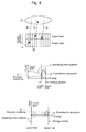
- a first embodiment of the present invention is PET equipment or the like on which, as shown in Fig. 9 , a three-dimensional detector 20 is mounted, and the PET equipment in which, as shown in Fig. 10 , a detection depth is limited at a lower energy region as well to utilize detector scattering and, as shown in Fig. 11 , a mechanism is provided for distinguishing between an event C scattered inside a body under testing 6 and an event B which imparts a portion of energy to the detector 20 after scattering inside the detector 20.
- the PET equipment or the like having a three-dimensional detector can be further increased in sensitivity, while the deterioration of positional information is prevented.
- Fig. 12 shows procedures of coincidence.
- the need is eliminated for using detecting elements of the same type on all layers when the detecting elements are stacked.
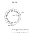
- an inexpensive detecting element 20B lower in effective atomic number is used on a lower layer unlike on an upper layer which requires an expensive detecting element 20A higher in effective atomic number, thus making it possible to use different types of detecting elements.
- the detecting element 20A on the upper layer is made long enough in length to stop scattered radiation but made shorter in length than the detecting element 20B on the lower layer, thereby realizing PET equipment lower in cost but higher in performance.
- a third embodiment of the present invention is PET equipment or the like on which, as shown in Fig. 9 , a three-dimensional detector 20 is mounted, and in which as shown in Fig. 14 , a weight is given to a detection event depending on a detection position and energy, thereby acquiring histograms.
- a fourth embodiment is that in which a detection event is stored as list mode data and, on image reconfiguration, a weight is given to a detection position and energy, thereby performing the reconfiguration.
- a ratio of detector scattering to scattering from a scatterer at a low energy region is calculated in advance by simulation or the like, thereby tabulating a weighting depending on a detection depth (layer) and energy.
- the weight is set in proportion to a ratio of detector scattering to scattering from a scatterer, for example.
- calculation is made by setting the ratio to 1.0. In other cases, the calculation is made by setting the ratio to 0.0.
- more detailed energy information is utilized than in the first or second embodiment, by which a mixture ratio of scattering from an object (scatterer) is reduced to effectively use a detector scattering event and also to improve a signal to noise ratio.
- three-dimensional detectors 20 each of which is made up of four stacked layers of a GSO scintillator measuring 2.9 mm x 2.9 mm x 7.5 mm were used to constitute a detector ring measuring 39 cm in ring diameter and 26 cm in length.
- a cylindrical phantom measuring 20 cm in diameter and 20 cm in length was filled with water and a pair of 20 cm-across linear radiation sources which emit a pair of radiation at 511 keV were installed on the central axis.
- energy windows are the same on all layers, for example, 400 to 600 keV.
- an energy window from 400 to 600 keV was provided on a first layer, while two energy windows from 100 to 300 keV and 400 to 600 keV were provided on a second to a fourth layer. More specifically, provided was an energy window from 100 to 600 keV excluding a range from 300 to 400 keV.
- a plurality of energy windows may be installed whenever necessary, which is different from the conventional PET equipment.
- Fig. 17 shows an energy spectrum of (A) true coincidence and that of (B) scatter coincidence. It is apparent that as the layer goes further down, influence of scattered radiation from a body under testing shown in (B) is reduced.
- Fig. 18 shows a change in (A) relative sensitivity and (B) scatter fraction (ratio at which object scattering is contained in measured data) when the lower limit of an energy window is changed.
- the lower limit 400 keV of the energy window is given as 100.
- the present invention is able to provide a higher sensitivity while suppressing an increase in scatter fraction.
- the present invention is applied to PET equipment.
- the present invention shall not be limited thereto but may be applied to other nuclear medical imaging equipment such as positron imaging equipment and also to radiation detecting equipment in general.
- the three-dimensional detector shall not be limited to the type shown in Fig. 3 and also acceptable is that which is able to distinguish a position in a depth direction in an analog manner.
- the present invention is applicable to nuclear medical imaging equipment such as positron imaging equipment and also to radiation detecting equipment in general, in addition to PET equipment.
Landscapes
- Health & Medical Sciences (AREA)
- Physics & Mathematics (AREA)
- Life Sciences & Earth Sciences (AREA)
- Spectroscopy & Molecular Physics (AREA)
- Molecular Biology (AREA)
- High Energy & Nuclear Physics (AREA)
- General Physics & Mathematics (AREA)
- Biomedical Technology (AREA)
- Optics & Photonics (AREA)
- Nuclear Medicine, Radiotherapy & Molecular Imaging (AREA)
- Medical Informatics (AREA)
- General Health & Medical Sciences (AREA)
- Engineering & Computer Science (AREA)
- Nuclear Medicine (AREA)
- Measurement Of Radiation (AREA)
Abstract
Description
- The present invention relates to a radiation detecting method and equipment thereof, and in particular to a radiation detecting method utilizing energy information and positional information preferably used in positron imaging equipment or positron emission tomography (PET) equipment and to the equipment thereof.
- As shown in
Fig. 1 , PET equipment is known in which positrons emitted from apositron emission nuclide 8 by the decay of +β undergo pair annihilation with surrounding electrons, and thus generatedannihilation radiations nuclide 8 is present can be localized on one line segment connecting between the pair of detectors 10a, 10b (coincidence line: line-of-response: LOR). When an axis from the head of a body under testing to the feet is defined as a body axis, a distribution of the nuclide on a planar surface intersecting perpendicularly with the body axis is obtained by image reconfiguration in two-dimensional mode from data of the coincidence line determined on the planar surface in various directions. - A
PET detector 10 is a collection of micro-detecting elements, the cross section of which is approximately 5 mm by 5 mm, and requires approximately 2 cm to 3 cm in thickness in order to detect at high probability a pair ofannihilation radiations detectors 10 are in general arranged in a ring shape so as to cover a subject, as shown inFig. 2 . However, radiation which is made incident obliquely into thedetector 10 will cause a measurement error so as to deteriorate spatial resolution, for which there is no choice but to make the diameter of a ring much larger than the visual field. - In PET equipment, in order to acquire a higher detectability, a three-dimensional detector has been developed for detecting a depth position as well at which the radiation is made incident into a detecting element. As exemplified in
Fig. 3 , detecting elements of the same type 21 to 24 are stacked on alight receiving element 26, and an optical reflector placed between the detecting elements is used to control the path of light, thus making it possible to localize a depth detecting position and energy from a difference in signals output from the light receiving element 26 (refer to Japanese Published Unexamined Patent Application No.2004-279057 light receiving element 26. - The above-described three-
dimensional detector 20 is able to improve the deterioration of spatial resolution resulting from radiation made incident obliquely into the detecting elements. Further, thedetector 20 can be brought closer to a body under testing than a detector used in the conventional PET equipment, thereby performing detection at a higher sensitivity. - On the other hand, as a method for improving the sensitivity, there is presented an idea of utilizing detector scattering shown in
Fig. 4(A) . In a conventional two-dimensional detector 10, as shown inFig. 4(B) and (C) , the detector scattering cannot be distinguished from scattering from a body under testing (also referred to as a scatterer) 6. Therefore, as shown inFig. 5 andFig. 6 , a lower limit of an energy window is adjusted to that of energy at photoelectric absorption A, by which both scattering events are eliminated as noises. - It is noted that, as shown in
Fig. 7 , ashield 12 for removing low-energy scattered radiation is installed on the upper face of thedetector 10, thus making it possible to remove scattered radiation from the body undertesting 6. However, the shield also removes partially a photoelectric absorption event (refer to G. Muehllehner: "Position camera with extended counting rate capability," J. Nucl. Med. Vol. 16, 663-657, 1975 (Non-Patent Document 2)). - Thus, PET equipment on which three-dimensional detectors are mounted is able to adopt an arrangement of the detectors so as to give a higher sensitivity than the conventional PET equipment. Nevertheless, there is a disadvantage that a high sensitivity measurement method and a great amount of information that the PET equipment has in principle are not yet utilized to a full extent.
- The present invention has been made in order to solve the above disadvantage, an object of which is to obtain scattering components inside a detector which would be otherwise discarded, thereby improving the sensitivity of detection.
- An event scattered in the body of a subject undergoes energy loss before being made incident into a detector, and as the event is decreased in energy more greatly than 511 keV at the time when the event is made incident into the detector, there is a higher probability that the event may impart all the energy on an upper layer of the detector and halt. On the other hand, an event scattered only at a detecting element has 511 keV in energy at the time when the event is made incident, and scattered inside a crystal once or scattered repeatedly a plurality of times. Thereafter, the event will finally impart all the energy at 511 keV or will impart some of the energy and escape outside the detector, with the remaining energy retained. Where the event does not scatter in the body but imparts all the energy at 511 keV to a detecting element, the event is detected inside an energy window shown in
Fig. 5 . However, where the event imparts only some of the energy, the event may be out of the energy window despite the fact that it has useful positional information. Therefore, in the conventional PET equipment, as shown inFig. 4 , a true coincidence B scattered inside a detector or a scatter coincidence C cannot be identified, whereby the coincidence B having useful positional information for the most part has been discarded. - As shown in
Fig. 8 , since the three-dimensional detector 20 is able to reduce scattering from a scatterer (scatter coincidence) C at detecting elements on a lower layer, thedetector 20 is able to utilize as a coincidence the detector scattering B as well by decreasing a lower limit of the energy window to a lower limit of detector scattering energy. The present invention is to provide a method in which the above-described events are effectively utilized to improve the sensitivity of radiation detecting equipment. A ratio of detector scattering to scattering from a body under testing is expected to be different depending on the depth at which radiation is detected and energy imparted. Therefore, if a detection position in a depth direction detected by a three-dimensional detector and energy information can be obtained, it is possible to obtain scattering components inside the detector at a region excluding that large in scattering components from a body under testing. Further, when a detection position in a depth direction detected by the three-dimensional detector and energy information are obtained, energy large in scattering components from the body under testing is decreased in weight and energy few in scattering components from the body under testing is increased in weight to acquire data, thus making it possible to obtain scattering components inside the detector, while a mixture ratio of scattering components from the body under testing is minimized. - The present invention has been made, with attention given to the above description, and has solved the problem by procedures in which upon detection of radiation by using a detector capable of distinguishing a detection position in a depth direction and energy, an energy window for distinguishing between a signal and noise is changed depending on the detection position in the depth direction, thus making it possible to obtain scattering components inside the detector.
- Further, the present invention is to provide radiation detecting equipment which detects radiation by using a detector capable of distinguishing a detection position in a depth direction and energy, and the radiation detecting equipment utilizing energy information and positional information in which an energy window for distinguishing between a signal and noise is changed depending on a detection position in a depth direction, thus making it possible to obtain scattering components inside the detector.
- In this case, the present invention is able to provide different detecting elements depending on a detection position in a depth direction.
- The present invention has solved the above problem by procedures in which upon detection of radiation by using a three-dimensional detector capable of distinguishing a detection position in a depth direction and energy, a weight is given to a detection event depending on the detection position in the depth direction and energy information, thus making it possible to obtain scattering components inside a detector.
- According to the present invention, scattering components inside a detector can be obtained to increase the sensitivity of the detector. Thereby, PET equipment, positron imaging equipment and others can be increased in sensitivity.
- Further, a weight is given to a detection event depending on a detection position in a depth direction and energy information to utilize more detailed energy information, by which a mixture ratio of scattering from an object (scatterer) is reduced to utilize a detector scattering event and improve a signal to noise ratio.
-
-
Fig. 1 is a view showing a principle of PET equipment. -
Fig. 2 is a view showing a whole constitution of the conventional PET equipment. -
Fig. 3 is a perspective view showing a three-dimensional detector presented in Patent Document 1. -
Fig. 4 is a view showing interactions of gamma rays and energy spectrum for describing a principle of the present invention. -
Fig. 5 is a view showing a method for removing scattered radiation by a conventional energy window. -
Fig. 6 is a view showing data processing by a conventional method. -
Fig. 7 is a view showing a method for removing scattered radiation by a conventional shield. -
Fig. 8 is a view showing the principle of the present invention. -
Fig. 9 is a view showing a first embodiment of PET equipment in which the present invention is utilized. -
Fig. 10 is a flow chart showing data processing procedures of the first embodiment. -
Fig. 11 is a view showing a state of radiation made incident of the first embodiment. -
Fig. 12 is a flow chart showing coincidence procedures of the first embodiment. -
Fig. 13 is a view showing a second embodiment of the PET equipment utilizing the present invention. -
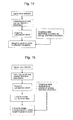
Fig. 14 is also a flow chart showing processing procedures of a third embodiment. -
Fig. 15 is also a flow chart showing processing procedures in a fourth embodiment. -
Fig. 16 is a view showing an energy window of the embodiments. -
Fig. 17 is a view showing an energy spectrum of (A) true coincidence and that of (B) scattered coincidence in a comparative manner. -
Fig. 18 is also a view showing (A) sensitivity and (B) scatter fraction in a comparative manner. - Hereinafter, a description will be given in detail for embodiments of the present invention by referring to the drawings.
- A first embodiment of the present invention is PET equipment or the like on which, as shown in
Fig. 9 , a three-dimensional detector 20 is mounted, and the PET equipment in which, as shown inFig. 10 , a detection depth is limited at a lower energy region as well to utilize detector scattering and, as shown inFig. 11 , a mechanism is provided for distinguishing between an event C scattered inside a body undertesting 6 and an event B which imparts a portion of energy to thedetector 20 after scattering inside thedetector 20. Thereby, the PET equipment or the like having a three-dimensional detector can be further increased in sensitivity, while the deterioration of positional information is prevented. -
Fig. 12 shows procedures of coincidence. - Further, in the present invention, the need is eliminated for using detecting elements of the same type on all layers when the detecting elements are stacked. As described in the second embodiment shown in
Fig. 13 , an inexpensive detectingelement 20B lower in effective atomic number is used on a lower layer unlike on an upper layer which requires an expensive detectingelement 20A higher in effective atomic number, thus making it possible to use different types of detecting elements. In this case, the detectingelement 20A on the upper layer is made long enough in length to stop scattered radiation but made shorter in length than the detectingelement 20B on the lower layer, thereby realizing PET equipment lower in cost but higher in performance. - Alternatively, it is possible to increase the sensitivity of PET equipment in which only detecting elements lower in effective atomic number such as semiconductor detectors are used.
- A third embodiment of the present invention is PET equipment or the like on which, as shown in
Fig. 9 , a three-dimensional detector 20 is mounted, and in which as shown inFig. 14 , a weight is given to a detection event depending on a detection position and energy, thereby acquiring histograms. - Further, as shown in
Fig. 15 , a fourth embodiment is that in which a detection event is stored as list mode data and, on image reconfiguration, a weight is given to a detection position and energy, thereby performing the reconfiguration. - In this case, as shown in
Fig. 8 , a ratio of detector scattering to scattering from a scatterer at a low energy region is calculated in advance by simulation or the like, thereby tabulating a weighting depending on a detection depth (layer) and energy. The weight is set in proportion to a ratio of detector scattering to scattering from a scatterer, for example. Alternatively, in a case where a ratio of detector scattering to scattering from a scatterer is in excess of a predetermined value, calculation is made by setting the ratio to 1.0. In other cases, the calculation is made by setting the ratio to 0.0. - As described in the third and fourth embodiments, more detailed energy information is utilized than in the first or second embodiment, by which a mixture ratio of scattering from an object (scatterer) is reduced to effectively use a detector scattering event and also to improve a signal to noise ratio.
- A simulation was performed by using the test model of PET equipment for the head developed by the applicant and others "jPET-D4" (refertoE.Yoshida, K. Kitamura, T. Tsuda, et. al. : "Energy spectra analysis of four-layer DOI detector for brain PET scanner: jPET-D4," Nucl. Instr. Meth. A, 577, 664-669, 2006 (Non-Patent Document 3). In this equipment, three-
dimensional detectors 20 each of which is made up of four stacked layers of a GSO scintillator measuring 2.9 mm x 2.9 mm x 7.5 mm were used to constitute a detector ring measuring 39 cm in ring diameter and 26 cm in length. As a phantom simulating a body undertesting 6, a cylindrical phantom measuring 20 cm in diameter and 20 cm in length was filled with water and a pair of 20 cm-across linear radiation sources which emit a pair of radiation at 511 keV were installed on the central axis. - In a conventional method, energy windows are the same on all layers, for example, 400 to 600 keV. However, in a method according to the present invention, as shown in
Fig. 16 , an energy window from 400 to 600 keV was provided on a first layer, while two energy windows from 100 to 300 keV and 400 to 600 keV were provided on a second to a fourth layer. More specifically, provided was an energy window from 100 to 600 keV excluding a range from 300 to 400 keV. As described above, a plurality of energy windows may be installed whenever necessary, which is different from the conventional PET equipment. -
Fig. 17 shows an energy spectrum of (A) true coincidence and that of (B) scatter coincidence. It is apparent that as the layer goes further down, influence of scattered radiation from a body under testing shown in (B) is reduced. -
Fig. 18 shows a change in (A) relative sensitivity and (B) scatter fraction (ratio at which object scattering is contained in measured data) when the lower limit of an energy window is changed. In the relative sensitivity, thelower limit 400 keV of the energy window is given as 100. As apparent from this drawing, the present invention is able to provide a higher sensitivity while suppressing an increase in scatter fraction. - In the previous description, the present invention is applied to PET equipment. However, the present invention shall not be limited thereto but may be applied to other nuclear medical imaging equipment such as positron imaging equipment and also to radiation detecting equipment in general. Further, the three-dimensional detector shall not be limited to the type shown in
Fig. 3 and also acceptable is that which is able to distinguish a position in a depth direction in an analog manner. - The present invention is applicable to nuclear medical imaging equipment such as positron imaging equipment and also to radiation detecting equipment in general, in addition to PET equipment.
Claims (9)
- A radiation detecting method utilizing energy information and positional information, wherein
upon detection of radiation by using a detector capable of distinguishing a detection position in a depth direction and energy, an energy window for distinguishing between a signal or noise is changed depending on the detection position in the depth direction, thus making it possible to obtain scattering components inside the detector. - The radiation detecting method utilizing energy information and positional information according to claim 1, wherein
different detecting elements are used depending on a detection position in a depth direction. - Radiation detecting equipment which detects radiation by using a detector capable of distinguishing a detection position in a depth direction and energy, the radiation detecting equipment utilizing energy information and positional information, wherein
an energy window for distinguishing between a signal and noise is changed depending on a detection position in a depth direction, thus making it possible to obtain scattering components inside the detector. - The radiation detecting equipment utilizing energy information and positional information according to claim 3, wherein
different detecting elements are provided depending on a detection position in a depth direction. - The radiation detecting equipment according to claim 3 or claim 4, wherein
information on radiation of two or more energy windows few in scattering components is utilized for monoenergetic radiation, depending on a detection position in a depth direction. - Radiation detecting method utilizing energy information and positional information, wherein
upon detection of radiation by using a detector capable of distinguishing a detection position in a depth direction and energy, a weight is given to a detection event depending on the detection position in the depth direction and energy information, thus making it possible to obtain scattering components inside the detector. - The radiation detecting method utilizing energy information and positional information according to claim 6, wherein
different detecting elements are used depending on a detection position in a depth direction. - Radiation detecting equipment which detects radiation by using a detector capable of distinguishing a detection position in a depth direction and energy, the radiation detecting equipment utilizing energy information and positional information, wherein
a weight is given to a detection event depending on the detection position in the depth direction and the energy information, thus making it possible to obtain scattering components inside the detector. - The radiation detecting equipment utilizing energy information and positional information according to claim 8, wherein
different detecting elements are provided depending on a detection position in a depth direction.
Applications Claiming Priority (2)
| Application Number | Priority Date | Filing Date | Title |
|---|---|---|---|
| JP2007112925A JP2010032214A (en) | 2007-04-23 | 2007-04-23 | Radioactive ray detecting method and device utilizing energy and position information |
| PCT/JP2007/066940 WO2008136141A1 (en) | 2007-04-23 | 2007-08-30 | Radioactive ray detecting method and device utilizing energy and position information |
Publications (2)
| Publication Number | Publication Date |
|---|---|
| EP2138867A1 true EP2138867A1 (en) | 2009-12-30 |
| EP2138867A4 EP2138867A4 (en) | 2016-11-02 |
Family
ID=39943263
Family Applications (1)
| Application Number | Title | Priority Date | Filing Date |
|---|---|---|---|
| EP07806417.7A Withdrawn EP2138867A4 (en) | 2007-04-23 | 2007-08-30 | METHOD AND DEVICE FOR DETECTING RADIOACTIVE RADIATION USING ENERGY AND POSITION INFORMATION |
Country Status (5)
| Country | Link |
|---|---|
| US (1) | US8188437B2 (en) |
| EP (1) | EP2138867A4 (en) |
| JP (2) | JP2010032214A (en) |
| CN (1) | CN101688918B (en) |
| WO (1) | WO2008136141A1 (en) |
Families Citing this family (16)
| Publication number | Priority date | Publication date | Assignee | Title |
|---|---|---|---|---|
| JP5423433B2 (en) * | 2010-01-28 | 2014-02-19 | 株式会社島津製作所 | Nuclear medicine diagnostic equipment |
| JP5794765B2 (en) * | 2010-06-17 | 2015-10-14 | 株式会社東芝 | Nuclear medicine imaging apparatus and method of operating nuclear medicine imaging apparatus |
| JP5750685B2 (en) * | 2011-01-11 | 2015-07-22 | 国立研究開発法人放射線医学総合研究所 | PET apparatus and PET-MRI apparatus |
| US8502154B2 (en) * | 2011-04-21 | 2013-08-06 | Kabushiki Kaisha Toshiba | Method and system for organ specific PET imaging |
| US9207333B2 (en) * | 2011-04-21 | 2015-12-08 | Kabushiki Kaisha Toshiba | Geometry for PET imaging |
| US9322929B2 (en) * | 2011-04-21 | 2016-04-26 | Kabushiki Kaisha Toshiba | PET imaging system including detector elements of different design and performance |
| JP5996847B2 (en) * | 2011-07-06 | 2016-09-21 | 株式会社島津製作所 | Radiation tomography equipment |
| CN102648856B (en) * | 2012-04-28 | 2016-03-30 | 中国科学院高能物理研究所 | PET (positron emission tomography) scanner and meeting wherein sentence choosing method |
| CN103054604B (en) * | 2012-12-25 | 2015-04-01 | 沈阳东软派斯通医疗系统有限公司 | Method and device for converting energy information and position information of positron emission tomography (PET) system and PET system |
| JP5920930B2 (en) * | 2013-03-21 | 2016-05-18 | 株式会社日立製作所 | Gamma camera, SPECT apparatus, PET apparatus, and gamma ray measurement image generation method |
| CN103645491B (en) * | 2013-11-25 | 2016-12-07 | 中国科学院高能物理研究所 | Radioactive source localization method, Apparatus and system |
| CN104807391A (en) * | 2014-01-27 | 2015-07-29 | 核工业航测遥感中心 | Solid radium source central point measuring instrument and detecting method thereof |
| JP6256608B2 (en) * | 2014-07-04 | 2018-01-10 | 株式会社島津製作所 | Image reconstruction processing method |
| CN107970037B (en) * | 2016-10-24 | 2021-01-05 | 上海东软医疗科技有限公司 | Imaging method and imaging system |
| CN116134342A (en) * | 2020-09-09 | 2023-05-16 | 三菱化学株式会社 | Signal processing system, positron emission tomography apparatus and positron emission tomography method |
| CN114711800B (en) * | 2021-11-16 | 2024-07-30 | 武汉联影生命科学仪器有限公司 | Scattering event screening method, apparatus, PET system, electronic device, and storage medium |
Family Cites Families (11)
| Publication number | Priority date | Publication date | Assignee | Title |
|---|---|---|---|---|
| JPS62203078A (en) | 1986-02-28 | 1987-09-07 | Shimadzu Corp | Radiation position detector |
| FR2705791A1 (en) * | 1993-05-28 | 1994-12-02 | Schlumberger Ind Sa | X-ray detector for obtaining selective energy responses |
| JP2743796B2 (en) * | 1993-10-27 | 1998-04-22 | 株式会社島津製作所 | Correction method for nuclear medicine imaging device |
| JPH08136655A (en) * | 1994-11-08 | 1996-05-31 | Hitachi Medical Corp | Data collecting circuit for emission ct device |
| JP4142767B2 (en) * | 1998-05-25 | 2008-09-03 | 株式会社東芝 | Nuclear medicine diagnostic equipment |
| JP4659962B2 (en) * | 2000-10-04 | 2011-03-30 | 株式会社東芝 | Nuclear medicine diagnostic equipment |
| JP3815468B2 (en) * | 2002-10-07 | 2006-08-30 | 株式会社日立製作所 | Radiation detector, radiation detection element, and radiation imaging apparatus |
| JP4338177B2 (en) | 2003-03-12 | 2009-10-07 | 独立行政法人放射線医学総合研究所 | 3D radiation position detector |
| JP4727947B2 (en) * | 2004-05-21 | 2011-07-20 | 株式会社島津製作所 | Photodetection circuit |
| DE102004049677B3 (en) * | 2004-10-12 | 2006-06-14 | Siemens Ag | Detector assembly for use in a combined transmission / emission tomography device |
| WO2006107727A2 (en) * | 2005-04-01 | 2006-10-12 | San Diego State University Foundation | Edge-on sar scintillator devices and systems for enhanced spect, pet, and compton gamma cameras |
-
2007
- 2007-04-23 JP JP2007112925A patent/JP2010032214A/en active Pending
- 2007-08-30 EP EP07806417.7A patent/EP2138867A4/en not_active Withdrawn
- 2007-08-30 JP JP2009512860A patent/JP4660706B2/en not_active Expired - Fee Related
- 2007-08-30 CN CN2007800527130A patent/CN101688918B/en not_active Expired - Fee Related
- 2007-08-30 WO PCT/JP2007/066940 patent/WO2008136141A1/en not_active Ceased
- 2007-08-30 US US12/450,529 patent/US8188437B2/en not_active Expired - Fee Related
Non-Patent Citations (1)
| Title |
|---|
| See references of WO2008136141A1 * |
Also Published As
| Publication number | Publication date |
|---|---|
| WO2008136141A1 (en) | 2008-11-13 |
| EP2138867A4 (en) | 2016-11-02 |
| CN101688918A (en) | 2010-03-31 |
| CN101688918B (en) | 2012-10-10 |
| JP4660706B2 (en) | 2011-03-30 |
| US8188437B2 (en) | 2012-05-29 |
| JP2010032214A (en) | 2010-02-12 |
| US20100032574A1 (en) | 2010-02-11 |
| JPWO2008136141A1 (en) | 2010-07-29 |
Similar Documents
| Publication | Publication Date | Title |
|---|---|---|
| US8188437B2 (en) | Radiation detecting method utilizing energy information and positional information and equipment thereof | |
| CA2252993C (en) | Detector assembly for multi-modality scanners | |
| EP3210042B1 (en) | Detector component for an x-ray or gamma ray detector | |
| KR100991640B1 (en) | Nuclear Medicine Diagnostic Device, Morphological Tomography Diagnostic Device, Nuclear Medicine Data Processing Method and Morphological Tomography Image Processing Method | |
| CN104285161B (en) | SPECT/PET imaging system | |
| WO2016015061A1 (en) | Multiple spatial resolution scintillation detectors | |
| KR20030072328A (en) | Radiation detecting device for nuclear medicine diagnosis device and detecting method therefor | |
| US4843245A (en) | Scintillation detector for tomographs | |
| EP0106267A2 (en) | Apparatus for the diagnosis of body structures into which a gamma-emitting radioactive isotope has been introduced | |
| JP7769338B2 (en) | Apparatus for detecting, identifying, quantifying and/or locating gamma ray and neutron sources simultaneously | |
| Vaquero et al. | Performance characteristics of a compact position-sensitive LSO detector module | |
| JP2019200162A (en) | Pet device and method for acquiring gamma ray generation position of scattering coincidence counting in pet device | |
| WO2007043137A1 (en) | Nuclear medical diagnosis device | |
| JP2005208057A (en) | Gamma ray detector and gamma ray imaging device | |
| US6281504B1 (en) | Diagnostic apparatus for nuclear medicine | |
| CN115516339A (en) | Radiation detection system | |
| Rafecas et al. | A Monte Carlo study of high-resolution PET with granulated dual-layer detectors | |
| KR102568800B1 (en) | Radiation detection collimator and radiation detection device using the same | |
| JPH07113873A (en) | Scattering simultaneous counting measuring method by gamma-ray absorber of positron tomograph and the same tomograph | |
| EP4095565B1 (en) | Device for the detection of gamma rays with interaction depth and time-of-flight encoding | |
| Yamada et al. | Development of a small animal PET scanner using DOI detectors | |
| US7791030B2 (en) | Nuclear medical diagnostic device | |
| McIntosh et al. | Validation of a GATE Model of $^{176} $ Lu Intrinsic Radioactivity in LSO PET Systems | |
| US20230236328A1 (en) | Method and apparatus for improved photosensor light collection in a radiation detector | |
| Inadama et al. | Preliminary evaluation of four-layer BGO DOI-detector for PET |
Legal Events
| Date | Code | Title | Description |
|---|---|---|---|
| PUAI | Public reference made under article 153(3) epc to a published international application that has entered the european phase |
Free format text: ORIGINAL CODE: 0009012 |
|
| 17P | Request for examination filed |
Effective date: 20091007 |
|
| AK | Designated contracting states |
Kind code of ref document: A1 Designated state(s): AT BE BG CH CY CZ DE DK EE ES FI FR GB GR HU IE IS IT LI LT LU LV MC MT NL PL PT RO SE SI SK TR |
|
| DAX | Request for extension of the european patent (deleted) | ||
| RAP1 | Party data changed (applicant data changed or rights of an application transferred) |
Owner name: NATIONAL INSTITUTES FOR QUANTUM AND RADIOLOGICAL S Owner name: SHIMADZU CORPORATION |
|
| RA4 | Supplementary search report drawn up and despatched (corrected) |
Effective date: 20160930 |
|
| RIC1 | Information provided on ipc code assigned before grant |
Ipc: G01T 1/164 20060101ALI20160926BHEP Ipc: G01T 1/161 20060101ALI20160926BHEP Ipc: G01T 1/20 20060101AFI20160926BHEP |
|
| STAA | Information on the status of an ep patent application or granted ep patent |
Free format text: STATUS: THE APPLICATION IS DEEMED TO BE WITHDRAWN |
|
| 18D | Application deemed to be withdrawn |
Effective date: 20170429 |