EP2138746A1 - Gasket - Google Patents
Gasket Download PDFInfo
- Publication number
- EP2138746A1 EP2138746A1 EP08740126A EP08740126A EP2138746A1 EP 2138746 A1 EP2138746 A1 EP 2138746A1 EP 08740126 A EP08740126 A EP 08740126A EP 08740126 A EP08740126 A EP 08740126A EP 2138746 A1 EP2138746 A1 EP 2138746A1
- Authority
- EP
- European Patent Office
- Prior art keywords
- gasket
- metal ring
- foaming
- ring
- face
- Prior art date
- Legal status (The legal status is an assumption and is not a legal conclusion. Google has not performed a legal analysis and makes no representation as to the accuracy of the status listed.)
- Granted
Links
Images





Classifications
-
- F—MECHANICAL ENGINEERING; LIGHTING; HEATING; WEAPONS; BLASTING
- F16—ENGINEERING ELEMENTS AND UNITS; GENERAL MEASURES FOR PRODUCING AND MAINTAINING EFFECTIVE FUNCTIONING OF MACHINES OR INSTALLATIONS; THERMAL INSULATION IN GENERAL
- F16J—PISTONS; CYLINDERS; SEALINGS
- F16J15/00—Sealings
- F16J15/16—Sealings between relatively-moving surfaces
- F16J15/34—Sealings between relatively-moving surfaces with slip-ring pressed against a more or less radial face on one member
- F16J15/38—Sealings between relatively-moving surfaces with slip-ring pressed against a more or less radial face on one member sealed by a packing
-
- F—MECHANICAL ENGINEERING; LIGHTING; HEATING; WEAPONS; BLASTING
- F16—ENGINEERING ELEMENTS AND UNITS; GENERAL MEASURES FOR PRODUCING AND MAINTAINING EFFECTIVE FUNCTIONING OF MACHINES OR INSTALLATIONS; THERMAL INSULATION IN GENERAL
- F16J—PISTONS; CYLINDERS; SEALINGS
- F16J15/00—Sealings
- F16J15/02—Sealings between relatively-stationary surfaces
- F16J15/06—Sealings between relatively-stationary surfaces with solid packing compressed between sealing surfaces
- F16J15/10—Sealings between relatively-stationary surfaces with solid packing compressed between sealing surfaces with non-metallic packing
- F16J15/12—Sealings between relatively-stationary surfaces with solid packing compressed between sealing surfaces with non-metallic packing with metal reinforcement or covering
- F16J15/121—Sealings between relatively-stationary surfaces with solid packing compressed between sealing surfaces with non-metallic packing with metal reinforcement or covering with metal reinforcement
Definitions
- the present invention relates to a gasket used for preventing leakage of sealed fluid such as gas or liquid from a space between components, in, for example, a mechanical seal and the like.
- this invention relates to a gasket having configuration wherein a cylindrical ring is covered by a rubber.
- a sealing device such as a mechanical seal and the like is used for sealing refrigerant at an inside of a machine.
- a gasket is interposed therebetween.
- a gasket having configuration wherein a circumference of a cylindrical ring is covered by a rubber as disclosed in Japanese Patent Laid Open No. 2007-24151 (referred as Patent Document 1).
- a purpose of the invention is to provide a gasket which is available to seal sealed fluid appropriately without foaming breakage of a rubber material even in a high pressure environment with significant pressure variation such as a compressor employing carbon dioxide gas (CO 2 ) as refrigerant.
- CO 2 carbon dioxide gas
- An invention of the present invention as a result of intense study of analyzing foaming breakage occurs at a boundary face of a cylindrical ring and a rubber material, and has found that the foaming breakage occurs by a cause as follows. Namely, a gas as sealed fluid penetrates to a rubber material, however, when a machine inside becomes high pressure, the gas penetrates the robber material, and the penetrated gas exits to the inside of the machine (or exits to environment side) when an inside pressure of the machine depressed relatively by variation of the pressure.
- the gas penetrates to the rubber material has a property that it becomes stable easily at the boundary face of the cylindrical ring (a cylindrical ring surface), the gas exists on the surface of the cylindrical ring can be expanded by small energy with respect to an internal of the rubber material.
- CO 2 carbonate dioxide gas
- the foaming breakage is confirmed at an inboard end portion of the cylindrical ring (corner portion of the edge) is due to that bonding between the cylindrical ring and the rubber material being relatively weak since adhesive agent is difficult to interpose between a space of the cylindrical ring and the rubber material at the edge portion of the cylindrical ring, as a result, non-uniformity arises at somewhere of the bonding portion of the cylindrical ring and the rubber material, the load can be concentrated easily at a portion where the bonding force is weak, thus foaming breakage can easily be occurred at the edge portion.
- a corner portion (edge) does not exist at an end portion of the cylindrical metal ring substantially, since the end portion of the cylindrical metal ring is formed as a curved surface with a radius more than a predetermined length. Therefore, foaming breakage of the rubber material that frequently occurred at the edge portion can be prevented. Further, bondage forces of the cylindrical metal ring and the rubber material becomes about equal at whole area covered by the rubber material. As a result, in a high pressure environment with significant pressure variation such as a compressor employing carbon dioxide gas (CO 2 ) as refrigerant, it is possible to provide a gasket available to seal sealed fluid appropriately without foaming breakage of the rubber material.
- CO 2 carbon dioxide gas
- a gasket of the present invention comprises a cylindrical metal ring, and a rubber layer covering its inner and outer circumferential surfaces and at least one end portion continuously, wherein an angular portion of said end portion of said cylindrical metal ring covered by said rubber material is subjected to corner chamfering (C-chamfering) so that a width of chamfer is 0.1 mm or more and a width of an end face is 0.06 mm or more.
- C-chamfering corner chamfering
- the gasket having such the constitution because the end portion of the metal ring is subjected to C-chamfering with the chamfering width a predetermined length or more as well as the end portion of the metal ring was formed so that a width of an end face rest of the metal ring end portion more than predetermined length, there is no corner portion (edge) substantially at the end portion of the metal ring. Therefore, foaming breakage of the rubber material that frequently occurred at the edge portion can be prevented. Further, bondage forces of the cylindrical metal ring and the rubber material becomes about equal at whole area covered by the rubber material. As a result, in a high pressure environment with significant pressure variation such as a compressor employing carbon dioxide gas (CO 2 ) as refrigerant, it is possible to provide a gasket available to seal sealed fluid appropriately without foaming breakage of the rubber material.
- CO 2 carbon dioxide gas
- a thickness of the rubber layer of the gasket of the present invention is 0.7 mm or less.
- the gasket having such constitution, since a thickness of the rubber material (rubber layer) is formed as thin significantly, gas penetrated into the rubber material exits from the rubber material immediately when an inboard side becomes low pressure. Thus, it is possible to reduce possibility of causing rubber material cracking by foaming the penetrate gas in the rubber member.
- Fig. 1 is a schematic cross sectional view showing a constitution of the sealing device.
- a sealing device 3 is equipped between a housing 1 of a compressor and a shaft 2 which is located so as to communicate an inside (inboard) and an outside (environment) of a compressor with penetrating an axial bore 11 of the housing.
- the shaft 2 drives a mechanism of the inside of the compressor (inboard) by a driving force from a crank axis of an engine at environment side which is transmitted via an electromagnetic crutch and the like not shown and rotated thereby.
- a sealing device 3 comprises a mating ring 30 which is a stationary side sliding ring equipped as a non-rotational status to the housing 1, a seal ring 40 which is a rotational side sliding ring 40 equipped to the shaft 2 side integrally rotates with the shaft 2, and a gasket 50 according to the present invention which is interposed between the mating ring 30 and the housing 1. Also, the sealing device 3 comprises a case 60, a coiled wave spring 70 and an O-ring 81 as a constitution so that the seal ring 40 slides over the shaft 2.
- the mating ring 30 and the seal ling 40 are arranged so as to face each other along an axial direction of the shaft 2 to seal the sealed fluid at a sealed sliding face S.
- the inboard sealed fluid is sealed so as not to leak or flow to the environment side.
- a space P of an outer circumferential side of a right side sealed sliding face S of the housing 1 is an inboard space to which carbon dioxide gas (CO 2 ) as sealed fluid is congested, and a space A from an inner circumferential side of the sealed sliding face S reaches to a left side of the housing 1 is an environment side (outboard) space.
- CO 2 carbon dioxide gas
- the mating ring 30 is received at an annular recess portion 12 formed as diameter expansion at an inboard side opening portion of the axial bore 11 of the housing 1.
- the mating ring 30 is engaged into the annular recess portion 12 with interposing the gasket 50 according to the present invention at an outer circumferential face 30b.
- An end face of the mating ring 30 at the sealing ring 40 side is formed as a sliding face 30a to which an end face 41a of a sliding notch 41, as a sliding face of the seal ring 40, tightly contacts rotatably.
- the seal ring 40 is arranged at the inboard side of the mating ring 30 and is fit to an outer circumferential face of the shaft 2 movably to an axial direction via the O-ring 81.
- a sliding notch 41 projected to a direction of the mating ring 30 is formed at an end face at the mating ring 30 side of the seal ring 40, an end face 41a of the sliding notch 41 slidably contacts tightly to the sliding face 30a of the mating ring 30.
- the seal ring 40 is formed by, for example, carbon sliding material, and the mating ring 30 is formed by rigid sliding material having large Young's modulus with respect to the carbon sliding material (for example, ceramic such as SiC and the like).
- the O-ring 81 is equipped to the seal ring 40 with a status received in an O-ring mount recess portion 43 formed on an inner circumferential face of an end portion at a back face side of the seal ring 40 (a face opposite to the mating ring 30).
- a spring hold 71 which is a metal plate abuts a back face of the seal ring 40, an inside diameter thereof extends so as to cover a rear of the O-ring mount recess portion 43 of the seal ring 40.
- a case 60 composed of a collar shape metal plate is located at a back face side of the spring holder 71.
- the case 60 is locked towards the axial direction of the shaft 2 by abutting to a first gap portion 21 of the outer circumferential surface of the shaft 2.
- the case 60 is composed to engage with a notch 26 portion formed at a part of the first gap portion 21 of the shaft 2, thereby non-movable towards a circumferential direction against the shaft 2, namely, fit with the shaft 2 so as to rotate integrally with the shaft 2 accompanied with rotation of the shaft 2.
- the coiled wave spring 70 is interposed between the spring holder 71 and the case 60 with appropriately compressed status to an axial direction, thereby the seal ring 40 is biased to a direction of the mating ring 30 via the spring holder 71.
- a plurality of engaging pawl 61 extended to the axial direction are formed with equally space, the pawls engage with a plurality of engaging notch 42 formed as equally spaced similarly at an outer circumferential side of the seal ring 40.
- the seal ring 40 becomes a status movable to the axial direction of the shaft 2, and equipped with the shaft 2 with a status not movable (integrally rotating status) to the circumferential direction of the shaft 2 (rotational direction).
- an applying force by the coiled wave spring 70 is given to the seal ring 40 with the axial direction of the shaft 2, and the edge face 41a of the sliding notch 41 is compressed with an appropriate surface pressing force to the sliding face 30a of the mating ring 30.
- the seal ring 40 rotates integrally with the shaft 2 by a rotational torque from the shaft 2 via the case 60.
- the first gap portion 21 is formed having tapered shape wherein the notch portion 26 are formed appropriately at a position to which the end portion of the case 60 is connected, also, a gap portion (a second gap portion) 22 is formed at a position corresponding to an inner circumference of the seal ring 40.
- the first gap portion 21 and the second gap portion 22 are as a boundary, in the shaft 2, a small diameter portion 23 which through an axis hole 11 of the housing 1 at environmental side with respect to the first gap portion 21 and an inner circumferential side of the mating ring 30 is formed, a middle diameter portion 24 to which a seal ring 40 between the first gap portion 21 and the second gap portion 22 slides over movably towards an axial direction via the O-ring 81 is formed, and a large diameter portion 25 of which an inboard portion with respect to the second portion 22 is formed.
- the gasket 50 is interposed between an inner circumferential face of an annular recess portion 12 of the housing 1 and the mating ring 30, the gasket 50 is a cylindrical shape member to prevent sealed fluid leaks from a space between the housing 1 and the mating ring 30 to environmental side.
- Constitution of the gasket is shown in Fig. 2 to Fig. 4 .
- Fig. 2 is a cross sectional view showing whole constitution of the gasket 50
- Fig. 3 and Fig. 4 are enlarged views of an end portion of inboard side of the gasket 50 respectively, and showing two embodiments of the gasket 50.
- the gasket 50 comprises a metal ring 51 which is a thin plate ring member made of metal and a rubber portion 58 which is a thin layer made of rubber member formed on about whole area of a circumferential face thereof. Namely, it has a constitution that the metal ring 51 is covered by the rubber portion 58.
- the rubber portion 58 covers continuously an inner circumferential face 51a and an outer circumferential face 51b and an end face 51c of inboard side (a side exposed to the sealed fluid) of the metal ring 51. Thicknesses of the rubber portion ea and eb are set in response to a seal face pressure and a seal property.
- a rubber portion thickness is preferably less than 0.7 mm considering gas permeability and the like. Note that, a lower limit may be thinner as possibly upon considering its procession.
- an environmental side of an end portion 57 of the gasket 50 (an end portion contacts to a bottom face of the annular recess portion 12 of the housing 1) is formed as having bottom shape by the metal ring 51 is bent to the inner diameter direction. Also, the metal ring 51 of the bent portion is exposed at an inner diameter corner portion of the gasket 50. In this manner, at the bent portion of the metal ring 51, the metal ring 51 contacts with a wall face of the housing 1 directly, heat radiation of the gasket 50 to the housing becomes be available efficiently.
- R-Chamfering is made to a corner portion of an inboard end portion 52 of the metal ring 51 of the gasket 50 as shown in Fig. 3 .
- a corner portion formed by the end face 51 and the inner circumferential face 51a and a corner portion formed by the end face 51c and the outer circumferential face 51b are formed as curved surfaces 53 and 54 having a round radius "R" respectively.
- the metal ring 51 is constituted that two faces does not have such as a right angle or a shape angle so-called "angular”.
- the round radius "R" of the curved surfaces 53 and 54 are preferably that low limits thereof are constituted as 0.1 mm not so as to constitute an angle substantially.
- an upper limit of the round radius "R” is not particularly limited, it is limited by a thickness of the metal ring 51.
- the upper limit of the round radius "R” is 1/2 of thickness of the metal ring 51.
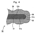
- the inboard end portion 52 of the metal ring 51 of the gasket 50 may be formed that a corner portion is corner chamfered shown in Fig. 4 .
- a corner portion formed by the end face 51c and the inner circumferential face 51a, and a corner portion formed by the end face 51c and the outer circumferential face 51b are chambered as angled by planes 55 and 56 having angle 45° with each faces respectively.
- the metal ring 51 is constituted that two faces does not have such as a right angle or a shape angle so-called "angular”, functions and effects similar with that an angle portion is constituted as a curved surface.
- widths of the C-chamfered face 55 and 56 is preferably their lower limit is 0.1 mm not so as to constitute an angle substantially.
- the end face 51 of the metal ring 41 remained as a result of the C-chamfered is preferably remains a width more than 0.06 mm not so as to constitute an angle substantially as similar.
- an outer diameter a of the gasket is 25.6mm
- an inner diameter b is 21mm
- a width c of the gasket 50 is 5.2mm.
- a thickness d of the metal ring 51 is 0.6mm
- the thicknesses ea and eb of the rubber portion 58 is less than 0.9 mm at the end portion of the metal ring 51.
- the metal ring 51 is formed by carbon steel, it may be formed by material having large heat conductivity such as cold rolled steel, copper alloy, aluminum alloy and the like. Also, it is preferable that material of the rubber member 58 is heat resistant rubber material. For example, FKM (fluoro rubber), CM (chloroprene rubber), H-NBR (hydrogenated nitrile rubber), II (butyl rubber), EPDM (ethylene propylene rubber) and the like are suitable.
- the experiment is performed by that a single body of the gasket which is an object of the verification is sintered in a liquefied carbon gas during of 25°C environment during 24 hours, then, heated in a furnace of 150°C during one hour, and exposing environment similar with an actual usage environment.
- the gasket is cut at a position of the inboard end face 51c of the metal ring 51, namely at a position Y shown in the drawing. Then, the cutting plane is observed from a direction X of Fig. 5B as to whether foaming (crack) is occurred.
- Fig. 6A and Fig. 6B examples are shown wherein the breakage of foaming is there and the breakage of foaming is not there.
- Fig. 6A is a picture showing the breakage of foaming is not occurred at the gasket 50
- Fig. 6B is a picture showing the breakage of foaming is not occurred.
- Fig. 6B it is clearly available to observe in case there is the breakage of foaming, as enclosed by dotted line.
- the gasket 50 wherein the inboard end portion 52 of the metal ring 51 is R chamfered as shown in Fig. 3
- the inboard end portion 52 of the metal ring is C chamfered as shown in Fig. 4 .
- Fig. 7 is a diagram showing as to whether the foaming exists or not at the rubber portion 58 of an end portion of the metal ring 51 in the gasket 50 having shape wherein the inboard end portion 52 of the metal ring 51 is R chamfered as shown in Fig. 3 .
- a lateral axis shows a round radius of a curve of R-chamfering
- a vertical axis shows a thickness of the rubber portion 58.
- white circular marks plotting are a condition wherein the foaming was not found and black circular marks plotting are a condition wherein the foaming was found.
- a thickness of the metal ring 51 is within 0.5 mm in any cases, an inner or an outer curved face 53 and 54 are formed by the same "R" radius.
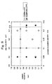
- Fig. 8 is a diagram showing shapes of end portion of the metal ring 51 and whether the foaming exists or not at the rubber portion 58 in the gasket 50 having shape wherein the inboard end portion 52 of the metal ring 51 is C chamfered as shown in Fig. 4 .
- a lateral axis shows a width of C-chamfering
- a vertical axis shows a thickness of the rubber portion 58.
- an upper portion of Fig. 8 a remaining width of the end face 51 of the metal ring 51 defied by chamfering width.
- white circular marks plotting are a condition wherein the foaming was not found and black circular marks plotting are a condition wherein the foaming was found.
- a thickness of the metal ring 51 is within 0.5 mm in any cases, inner and outer C-chamfering portions 55 and 56 are formed by the same C-chamfering width.
- the foaming is confirmed at the rubber portion 58 more than half number of samples, the foaming does not occur under the condition that the chamfering width is more than 0.1mm, despite the thickness of the rubber portion 58.
- the foaming is not confirmed in case that a width of the remaining end face 51c is until 0.06 mm (corresponding to 0.3 mm of the chamfering width), and is confirmed if it is below. It has been confirmed that due to this portion becomes a "corner" substantially, if the remaining end face 51c is too narrow, substantially.
- the foaming of the rubber portion 58 and the breakage of foaming of the rubber portion 58 can be prevented by the C-chamfering so that the a chamfering width of a shape of the inboard end portion 51c of the metal ring 51 is more than 0.1 mm with the end face 51c of the metal ring remains more than 0.06mm.
- Fig. 9 is a diagram showing a result of presence or absence of foaming (crack) by observing a single gasket 50 wherein the R-chamfering is performed to the inboard end portion 52 of the metal ring 51 as shown in Fig. 3 , sintering into a liquefied Freon gas having 25°environment during 24 hours, then heated in a furnace of 150°C during one hour, the gasket is cut at a position of the inboard end face 51c of the metal ring 51.
- white circular marks plotting are a condition wherein the foaming was not found and black circular marks plotting are a condition wherein the foaming was found.
- a thickness of the metal ring 51 is within 0.5 mm in any cases, inner and outer C-chamfering portions 55 and 56 are formed by the same C-chamfering width.
- the sealing device 3 of the present embodiment since a shape of the inboard end portion 52 of the metal ring 51 of the gasket 50 is formed as R chamfered at corner portions shown in Fig. 3 or C chamfered at corner portions shown in Fig. 4 , the angled portions are not substantially existed at the end portion of the metal ring 51. As a result, in a conventional gasket, concentrated foaming occurred in a rubber portion at corner portions of the end portion of the metal ring can be prevented. Also, because the rubber portion 58 can be connected with the metal ring 51 even at the end portion of the metal ring 51, a connecting force of the metal ring 51 and the rubber portion 58 may be uniformed at whole body of the gasket 50. As a result, the breakage of foaming of the rubber portion 58 at a boundary face of the metal ring 51 and the rubber portion 58 can be prevented.
- a gasket of the present invention is a sealing device to seal wherein carbon dioxide gas (CO 2 ) is sealed fluid, and is useful by applying a sealing device used for, e.g., a compressor of an automotive air conditioner. Also, a gasket of the present invention is favorable to use other arbitral sealing device, for example, an oil seal and the like.
Landscapes
- Engineering & Computer Science (AREA)
- General Engineering & Computer Science (AREA)
- Mechanical Engineering (AREA)
- Gasket Seals (AREA)
Abstract
Description
- The present invention relates to a gasket used for preventing leakage of sealed fluid such as gas or liquid from a space between components, in, for example, a mechanical seal and the like. Particularly, this invention relates to a gasket having configuration wherein a cylindrical ring is covered by a rubber.
- In a compressor used for automotive air conditioning apparatus and the like, a sealing device such as a mechanical seal and the like is used for sealing refrigerant at an inside of a machine. Also, for preventing leakage of sealed gas from a space between components of the sealing device or a space between the sealing device and a sealing equipment portion of a compressor, a gasket is interposed therebetween. As a preferable constitutional example, it has been known a gasket having configuration wherein a circumference of a cylindrical ring is covered by a rubber as disclosed in Japanese Patent Laid Open No.
2007-24151 - Patent Document 1: Japanese Patent Laid Open No.
2007-24151 - In the meantime, refrigerant used for an automotive air conditioning apparatus and the like has been changed from Freon R12(CF2CL2) to Freon R-134a which excludes chlorine (CI) which causes ozone depletion as part of depletion of ozone. However, after this, there has been a new problem that Freon greatly relates to a greenhouse effect which causes global warming even it is extremely small amount, because it absorbs long-wave (infrared ray) radiation. Therefore, in recent years, experiment for refrigerant instead of R134a in order to reduce such environmental burden, particularly, it has been considered to switch Freon gas (R-134a) to natural refrigerant such as carbon dioxide gas (CO2) and the like.
- However, when carbon dioxide gas (CO2) is used as refrigerant, an internal pressure of a compressor of an air conditioning apparatus becomes high pressure for example, it becomes 10 times in degree as compared from using Freon gas (R-134a), and its fluctuation range becomes larger. Then, in a sealing device of a compressor used in the condition like this, there is so-called foaming breakage at a rubber material when using a gasket wherein a circumferential cylindrical ring is covered by a rubber material. The foaming breakage of the rubber material at this time occurs at a boundary surface (a bonded part) of the cylindrical ring and the rubber material, particularly occurs concentrically at an edge portion of the cylindrical ring at an inside of a machine.
- The present invention is made by considering these problems, a purpose of the invention is to provide a gasket which is available to seal sealed fluid appropriately without foaming breakage of a rubber material even in a high pressure environment with significant pressure variation such as a compressor employing carbon dioxide gas (CO2) as refrigerant.
- An invention of the present invention, as a result of intense study of analyzing foaming breakage occurs at a boundary face of a cylindrical ring and a rubber material, and has found that the foaming breakage occurs by a cause as follows. Namely, a gas as sealed fluid penetrates to a rubber material, however, when a machine inside becomes high pressure, the gas penetrates the robber material, and the penetrated gas exits to the inside of the machine (or exits to environment side) when an inside pressure of the machine depressed relatively by variation of the pressure. On the other hand, the gas penetrates to the rubber material has a property that it becomes stable easily at the boundary face of the cylindrical ring (a cylindrical ring surface), the gas exists on the surface of the cylindrical ring can be expanded by small energy with respect to an internal of the rubber material. Thus, in compressor wherein carbonate dioxide gas (CO2) is used, since an inside pressure of a machine becomes extremely high pressure and pressure variation becomes larger as compared from using Freon, the gas expands largely before penetrating from the rubber material and the rubber material reaches the foaming breakage.
- Further, the foaming breakage is confirmed at an inboard end portion of the cylindrical ring (corner portion of the edge) is due to that bonding between the cylindrical ring and the rubber material being relatively weak since adhesive agent is difficult to interpose between a space of the cylindrical ring and the rubber material at the edge portion of the cylindrical ring, as a result, non-uniformity arises at somewhere of the bonding portion of the cylindrical ring and the rubber material, the load can be concentrated easily at a portion where the bonding force is weak, thus foaming breakage can easily be occurred at the edge portion.
- Therefore, the gasket of the present invention comprises a cylindrical metal ring, and a rubber layer which covers an inner circumferential face, an outer circumferential face and at least one end portion of said cylindrical metal ring continuously, wherein an angular portion of said end portion of said cylindrical metal ring covered by said rubber material is subjected to round chamfering (R-chamfering) so that a round radius "R" of a curved surface becomes R=0.1 mm or more.
- According to a gasket having such constitution, a corner portion (edge) does not exist at an end portion of the cylindrical metal ring substantially, since the end portion of the cylindrical metal ring is formed as a curved surface with a radius more than a predetermined length. Therefore, foaming breakage of the rubber material that frequently occurred at the edge portion can be prevented. Further, bondage forces of the cylindrical metal ring and the rubber material becomes about equal at whole area covered by the rubber material. As a result, in a high pressure environment with significant pressure variation such as a compressor employing carbon dioxide gas (CO2) as refrigerant, it is possible to provide a gasket available to seal sealed fluid appropriately without foaming breakage of the rubber material.
- Preferably, a gasket of the present invention comprises a cylindrical metal ring, and a rubber layer covering its inner and outer circumferential surfaces and at least one end portion continuously, wherein an angular portion of said end portion of said cylindrical metal ring covered by said rubber material is subjected to corner chamfering (C-chamfering) so that a width of chamfer is 0.1 mm or more and a width of an end face is 0.06 mm or more.
- According to the gasket having such the constitution, because the end portion of the metal ring is subjected to C-chamfering with the chamfering width a predetermined length or more as well as the end portion of the metal ring was formed so that a width of an end face rest of the metal ring end portion more than predetermined length, there is no corner portion (edge) substantially at the end portion of the metal ring. Therefore, foaming breakage of the rubber material that frequently occurred at the edge portion can be prevented. Further, bondage forces of the cylindrical metal ring and the rubber material becomes about equal at whole area covered by the rubber material. As a result, in a high pressure environment with significant pressure variation such as a compressor employing carbon dioxide gas (CO2) as refrigerant, it is possible to provide a gasket available to seal sealed fluid appropriately without foaming breakage of the rubber material.
- Also, preferably, a thickness of the rubber layer of the gasket of the present invention is 0.7 mm or less.
- According to the gasket having such constitution, since a thickness of the rubber material (rubber layer) is formed as thin significantly, gas penetrated into the rubber material exits from the rubber material immediately when an inboard side becomes low pressure. Thus, it is possible to reduce possibility of causing rubber material cracking by foaming the penetrate gas in the rubber member.
-
- [
Fig. 1 ]
Fig. 11 a schematic cross sectional view showing a structure of a sealing device of one embodiment of the present invention. - [
Fig. 2 ]
Fig. 2 is a cross sectional view showing whole structure of a gasket of the sealing device ofFig. 1 . - [
Fig. 3 ]
Fig. 3 is an enlarged view of an inboard end portion of the gasket shown inFig 2 showing a specific embodiment of a metal tube. - [
Fig. 4 ]
Fig. 4 is an enlarged view of an inboard end portion of the gasket shown inFig 2 showing another specific embodiment of the metal tube. - [
Fig. 5A ]
Fig. 5A is a first diagram for explaining an observation method of foaming breakage at a verification experiment of breakage of foaming of a gasket. - [
Fig. 5B ]
Fig. 5B is a second diagram for explaining an observation method of foaming breakage at a verification experiment of breakage of foaming of a gasket. - [
Fig. 6A ]
Fig. 6A is a diagram showing an example of observation image wherein breakage of foaming is not occurred. - [
Fig. 6B ]
Fig. 6B is a diagram showing an example of observation image wherein breakage of foaming is occurred. - [
Fig. 7 ]
Fig. 7 is a diagram showing an experimental result for verifying that the breakage of foaming is not occurred and condition thereof at the gasket shown inFig. 3 . - [
Fig. 8 ]
Fig. 8 is a diagram showing an experimental result for verifying that the breakage of foaming is not occurred and condition thereof at the gasket shown inFig. 4 . - [
Fig. 9 ]
Fig. 9 is a diagram showing a result of verifying experiment for breakage of foaming at the gasket shown inFig. 3 in case that seal object is Freon gas (R-134a) for comparison. - With respect embodiments of the present invention will be specified with reference to
Fig. 1 to Fig. 9 .
In the present embodiment, it will be specified a sealing device to seal carbon dioxide gas (CO2) as refrigerant applied to a compressor for an automotive air conditioner wherein a sealing device using a gasket according to the present invention.
Fig. 1 is a schematic cross sectional view showing a constitution of the sealing device. - As shown in
Fig. 1 , asealing device 3 is equipped between a housing 1 of a compressor and ashaft 2 which is located so as to communicate an inside (inboard) and an outside (environment) of a compressor with penetrating an axial bore 11 of the housing. Theshaft 2 drives a mechanism of the inside of the compressor (inboard) by a driving force from a crank axis of an engine at environment side which is transmitted via an electromagnetic crutch and the like not shown and rotated thereby. - A
sealing device 3 comprises amating ring 30 which is a stationary side sliding ring equipped as a non-rotational status to the housing 1, aseal ring 40 which is a rotationalside sliding ring 40 equipped to theshaft 2 side integrally rotates with theshaft 2, and agasket 50 according to the present invention which is interposed between themating ring 30 and the housing 1. Also, thesealing device 3 comprises acase 60, a coiledwave spring 70 and an O-ring 81 as a constitution so that theseal ring 40 slides over theshaft 2. - The
mating ring 30 and theseal ling 40 are arranged so as to face each other along an axial direction of theshaft 2 to seal the sealed fluid at a sealed sliding face S. Namely, the inboard sealed fluid is sealed so as not to leak or flow to the environment side.
Note that, inFig. 1 , a space P of an outer circumferential side of a right side sealed sliding face S of the housing 1 is an inboard space to which carbon dioxide gas (CO2) as sealed fluid is congested, and a space A from an inner circumferential side of the sealed sliding face S reaches to a left side of the housing 1 is an environment side (outboard) space. - The
mating ring 30 is received at anannular recess portion 12 formed as diameter expansion at an inboard side opening portion of the axial bore 11 of the housing 1. Themating ring 30 is engaged into theannular recess portion 12 with interposing thegasket 50 according to the present invention at an outercircumferential face 30b. An end face of themating ring 30 at the sealingring 40 side is formed as a slidingface 30a to which an end face 41a of a slidingnotch 41, as a sliding face of theseal ring 40, tightly contacts rotatably. - The
seal ring 40 is arranged at the inboard side of themating ring 30 and is fit to an outer circumferential face of theshaft 2 movably to an axial direction via the O-ring 81. A slidingnotch 41 projected to a direction of themating ring 30 is formed at an end face at themating ring 30 side of theseal ring 40, an end face 41a of the slidingnotch 41 slidably contacts tightly to the slidingface 30a of themating ring 30.
Theseal ring 40 is formed by, for example, carbon sliding material, and themating ring 30 is formed by rigid sliding material having large Young's modulus with respect to the carbon sliding material (for example, ceramic such as SiC and the like). - The O-
ring 81 is equipped to theseal ring 40 with a status received in an O-ringmount recess portion 43 formed on an inner circumferential face of an end portion at a back face side of the seal ring 40 (a face opposite to the mating ring 30).
A spring hold 71 which is a metal plate abuts a back face of theseal ring 40, an inside diameter thereof extends so as to cover a rear of the O-ringmount recess portion 43 of theseal ring 40.
Acase 60 composed of a collar shape metal plate is located at a back face side of thespring holder 71. - The
case 60 is locked towards the axial direction of theshaft 2 by abutting to afirst gap portion 21 of the outer circumferential surface of theshaft 2. Thecase 60 is composed to engage with anotch 26 portion formed at a part of thefirst gap portion 21 of theshaft 2, thereby non-movable towards a circumferential direction against theshaft 2, namely, fit with theshaft 2 so as to rotate integrally with theshaft 2 accompanied with rotation of theshaft 2. - The coiled
wave spring 70 is interposed between thespring holder 71 and thecase 60 with appropriately compressed status to an axial direction, thereby theseal ring 40 is biased to a direction of themating ring 30 via thespring holder 71.
Also, a plurality of engaging pawl 61 extended to the axial direction are formed with equally space, the pawls engage with a plurality of engaging notch 42 formed as equally spaced similarly at an outer circumferential side of theseal ring 40. Thereby, theseal ring 40 becomes a status movable to the axial direction of theshaft 2, and equipped with theshaft 2 with a status not movable (integrally rotating status) to the circumferential direction of the shaft 2 (rotational direction). - By the constitution like this, an applying force by the coiled
wave spring 70 is given to theseal ring 40 with the axial direction of theshaft 2, and the edge face 41a of the slidingnotch 41 is compressed with an appropriate surface pressing force to the slidingface 30a of themating ring 30. Also, theseal ring 40 rotates integrally with theshaft 2 by a rotational torque from theshaft 2 via thecase 60.
As a result, accompany with rotation of theshaft 2, the slidingface 30a of themating ring 30 and the sliding face 41 a at an end of the slidingnotch 41 of theseal ring 40 slide with tightly contact status to seal sealed fluid at a contact face (sealing slide face S) of the slidingface 30a of themating ring 30 and the sliding face 41 a of theseal ring 40. - Note that, as mentioned previously, in the
shaft 2, thefirst gap portion 21 is formed having tapered shape wherein thenotch portion 26 are formed appropriately at a position to which the end portion of thecase 60 is connected, also, a gap portion (a second gap portion) 22 is formed at a position corresponding to an inner circumference of theseal ring 40. Thefirst gap portion 21 and thesecond gap portion 22 are as a boundary, in theshaft 2, asmall diameter portion 23 which through an axis hole 11 of the housing 1 at environmental side with respect to thefirst gap portion 21 and an inner circumferential side of themating ring 30 is formed, amiddle diameter portion 24 to which aseal ring 40 between thefirst gap portion 21 and thesecond gap portion 22 slides over movably towards an axial direction via the O-ring 81 is formed, and alarge diameter portion 25 of which an inboard portion with respect to thesecond portion 22 is formed. - The
gasket 50 is interposed between an inner circumferential face of anannular recess portion 12 of the housing 1 and themating ring 30, thegasket 50 is a cylindrical shape member to prevent sealed fluid leaks from a space between the housing 1 and themating ring 30 to environmental side.
Constitution of the gasket is shown inFig. 2 to Fig. 4 .
Fig. 2 is a cross sectional view showing whole constitution of thegasket 50,Fig. 3 andFig. 4 are enlarged views of an end portion of inboard side of thegasket 50 respectively, and showing two embodiments of thegasket 50. - As shown in
Fig. 2 , thegasket 50 comprises ametal ring 51 which is a thin plate ring member made of metal and arubber portion 58 which is a thin layer made of rubber member formed on about whole area of a circumferential face thereof. Namely, it has a constitution that themetal ring 51 is covered by therubber portion 58. Therubber portion 58 covers continuously an innercircumferential face 51a and an outercircumferential face 51b and anend face 51c of inboard side (a side exposed to the sealed fluid) of themetal ring 51.
Thicknesses of the rubber portion ea and eb are set in response to a seal face pressure and a seal property. A rubber portion thickness is preferably less than 0.7 mm considering gas permeability and the like. Note that, a lower limit may be thinner as possibly upon considering its procession. - Also, an environmental side of an
end portion 57 of the gasket 50 (an end portion contacts to a bottom face of theannular recess portion 12 of the housing 1) is formed as having bottom shape by themetal ring 51 is bent to the inner diameter direction. Also, themetal ring 51 of the bent portion is exposed at an inner diameter corner portion of thegasket 50.
In this manner, at the bent portion of themetal ring 51, themetal ring 51 contacts with a wall face of the housing 1 directly, heat radiation of thegasket 50 to the housing becomes be available efficiently. - R-Chamfering is made to a corner portion of an
inboard end portion 52 of themetal ring 51 of thegasket 50 as shown inFig. 3 . Namely, a corner portion formed by theend face 51 and the innercircumferential face 51a and a corner portion formed by theend face 51c and the outercircumferential face 51b are formed ascurved surfaces inboard end portion 52 of thegasket 50, themetal ring 51 is constituted that two faces does not have such as a right angle or a shape angle so-called "angular".
Note that, the round radius "R" of thecurved surfaces metal ring 51. In case that thecurved surface 53 and thecurved surface 54 are formed as a same round radius "R", the upper limit of the round radius "R" is 1/2 of thickness of themetal ring 51. - Also, the
inboard end portion 52 of themetal ring 51 of thegasket 50 may be formed that a corner portion is corner chamfered shown inFig. 4 . Namely, a corner portion formed by theend face 51c and the innercircumferential face 51a, and a corner portion formed by theend face 51c and the outercircumferential face 51b are chambered as angled byplanes inboard end portion 52 of thegasket 50, themetal ring 51 is constituted that two faces does not have such as a right angle or a shape angle so-called "angular", functions and effects similar with that an angle portion is constituted as a curved surface.
Note that, widths of the C-chamferedface end face 51 of themetal ring 41 remained as a result of the C-chamfered is preferably remains a width more than 0.06 mm not so as to constitute an angle substantially as similar. - Note that, in the present embodiment, in the gasket having any shape shown in
Fig. 3 andFig. 4 , as shown inFig. 2 , an outer diameter a of the gasket is 25.6mm, an inner diameter b is 21mm, a width c of thegasket 50 is 5.2mm. Also, a thickness d of themetal ring 51 is 0.6mm, the thicknesses ea and eb of therubber portion 58 is less than 0.9 mm at the end portion of themetal ring 51. - Also, in the present embodiment, the
metal ring 51 is formed by carbon steel, it may be formed by material having large heat conductivity such as cold rolled steel, copper alloy, aluminum alloy and the like.
Also, it is preferable that material of therubber member 58 is heat resistant rubber material. For example, FKM (fluoro rubber), CM (chloroprene rubber), H-NBR (hydrogenated nitrile rubber), II (butyl rubber), EPDM (ethylene propylene rubber) and the like are suitable. - Here, with respect to foam is not occurred at the
rubber portion 58 of thegasket 50 in case that that the gasket is formed according to themetal ring 51 of theinboard end portion 52 of thegasket 50 is processed as such shape, verification results (experimental results) are shown inFig. 5A to Fig. 8 . - The experiment is performed by that a single body of the gasket which is an object of the verification is sintered in a liquefied carbon gas during of 25°C environment during 24 hours, then, heated in a furnace of 150°C during one hour, and exposing environment similar with an actual usage environment. When heating is finished, as shown in
Fig. 5A , the gasket is cut at a position of theinboard end face 51c of themetal ring 51, namely at a position Y shown in the drawing. Then, the cutting plane is observed from a direction X ofFig. 5B as to whether foaming (crack) is occurred. - In
Fig. 6A andFig. 6B , examples are shown wherein the breakage of foaming is there and the breakage of foaming is not there.Fig. 6A is a picture showing the breakage of foaming is not occurred at thegasket 50,Fig. 6B is a picture showing the breakage of foaming is not occurred.
InFig. 6B , it is clearly available to observe in case there is the breakage of foaming, as enclosed by dotted line.
In thegasket 50 wherein theinboard end portion 52 of themetal ring 51 is R chamfered as shown inFig. 3 and in thegasket 50 wherein theinboard end portion 52 of the metal ring is C chamfered as shown inFig. 4 , the above mentioned experiments and observations have been repeated with changing conditions.
The results are shown inFig. 7 andFig. 8 . -
Fig. 7 is a diagram showing as to whether the foaming exists or not at therubber portion 58 of an end portion of themetal ring 51 in thegasket 50 having shape wherein theinboard end portion 52 of themetal ring 51 is R chamfered as shown inFig. 3 . InFig. 7 , a lateral axis shows a round radius of a curve of R-chamfering, a vertical axis shows a thickness of therubber portion 58. In the drawing, white circular marks plotting are a condition wherein the foaming was not found and black circular marks plotting are a condition wherein the foaming was found.
Note that, a thickness of themetal ring 51 is within 0.5 mm in any cases, an inner or an outercurved face - As it is clear from
Fig. 7 , although in case that the radius "R" of the R-chamfering is 0.05mm, the foaming is confirmed at therubber portion 58 more than half number of samples, the foaming does not occur under the condition that the radius "R" is more than 0.1mm, despite the thickness of therubber portion 58.
Therefore, despite other conditions such as the thickness of therubber portion 58, the foaming of therubber portion 58 and the breakage of foaming of therubber portion 58 can be prevented by chamfering procession of theinboard end portion 52 of themetal ring 51 with a curved surface having more than the radius R=0.1mm. - Also,
Fig. 8 is a diagram showing shapes of end portion of themetal ring 51 and whether the foaming exists or not at therubber portion 58 in thegasket 50 having shape wherein theinboard end portion 52 of themetal ring 51 is C chamfered as shown inFig. 4 . InFig. 8 , a lateral axis shows a width of C-chamfering, a vertical axis shows a thickness of therubber portion 58. Also, an upper portion ofFig. 8 , a remaining width of theend face 51 of themetal ring 51 defied by chamfering width. In the drawing, white circular marks plotting are a condition wherein the foaming was not found and black circular marks plotting are a condition wherein the foaming was found.
Note that, a thickness of themetal ring 51 is within 0.5 mm in any cases, inner and outer C-chamferingportions - As it is clear from
Fig. 8 , although in case that the chamfering width of the C-chamfering is 0.05mm, the foaming is confirmed at therubber portion 58 more than half number of samples, the foaming does not occur under the condition that the chamfering width is more than 0.1mm, despite the thickness of therubber portion 58.
On the other hand, the foaming is not confirmed in case that a width of the remainingend face 51c is until 0.06 mm (corresponding to 0.3 mm of the chamfering width), and is confirmed if it is below. It has been confirmed that due to this portion becomes a "corner" substantially, if the remainingend face 51c is too narrow, substantially.
Therefore, when the C-chamfering, despite other conditions such as the thickness of therubber portion 58, the foaming of therubber portion 58 and the breakage of foaming of therubber portion 58 can be prevented by the C-chamfering so that the a chamfering width of a shape of theinboard end portion 51c of themetal ring 51 is more than 0.1 mm with theend face 51c of the metal ring remains more than 0.06mm. - Next, for comparing, a result for performing a similar experiment as to whether the breakage of foaming exist or not when Freon gas (R-134a) is used as an object medium of sealing (sealed fluid). The result is shown in
Fig. 9 .
Fig. 9 is a diagram showing a result of presence or absence of foaming (crack) by observing asingle gasket 50 wherein the R-chamfering is performed to theinboard end portion 52 of themetal ring 51 as shown inFig. 3 , sintering into a liquefied Freon gas having 25°environment during 24 hours, then heated in a furnace of 150°C during one hour, the gasket is cut at a position of theinboard end face 51c of themetal ring 51. In the drawing, white circular marks plotting are a condition wherein the foaming was not found and black circular marks plotting are a condition wherein the foaming was found.
Note that, a thickness of themetal ring 51 is within 0.5 mm in any cases, inner and outer C-chamferingportions - As shown in
Fig. 9 , when the sealing object is Freon gas (R-134a) in any shape of thegasket 50, the breakage of foaming is not occurred at therubber portion 58. As it is clear by comparing withFig. 7 , the breakage of foaming at thegasket 50 is not occurred under any condition including in case that the radius "R" of the R-chamfering is 0.05 mm in which the breakage of foaming was confirmed when the sealing object is carbon dioxide gas (CO2). - In this manner, according to the sealing object is carbon dioxide gas (CO2), it has been confirmed clearly that the foaming and the breakage of foaming of the
rubber portion 58 of thegasket 50 are occurred which were not occurred when the sealing object is Freon gas (R-134a). Then, in case that the sealing object is carbon dioxide gas (CO2), by making a shape of thegasket 50 as the present invention, it is clear that the foaming of therubber portion 58 can be prevented as well as the breakage of foaming of therubber potion 58 can be prevented too. Namely, it is confirmed clearly that thegasket 51 having themetal ring 51 defined be the present invention is quite effective when sealing carbon dioxide gas (CO2). - As explained above, according to the
sealing device 3 of the present embodiment, since a shape of theinboard end portion 52 of themetal ring 51 of thegasket 50 is formed as R chamfered at corner portions shown inFig. 3 or C chamfered at corner portions shown inFig. 4 , the angled portions are not substantially existed at the end portion of themetal ring 51. As a result, in a conventional gasket, concentrated foaming occurred in a rubber portion at corner portions of the end portion of the metal ring can be prevented.
Also, because therubber portion 58 can be connected with themetal ring 51 even at the end portion of themetal ring 51, a connecting force of themetal ring 51 and therubber portion 58 may be uniformed at whole body of thegasket 50. As a result, the breakage of foaming of therubber portion 58 at a boundary face of themetal ring 51 and therubber portion 58 can be prevented. - Note that, the above mentioned embodiments are described for easily understanding of the present invention, and it does not limit the present invention in anyway. Each elements disclosed in the present embodiment include all design around matters included in a technical scope of the present invention and equivalent matters, arbitral various modifications are available.
- A gasket of the present invention is a sealing device to seal wherein carbon dioxide gas (CO2) is sealed fluid, and is useful by applying a sealing device used for, e.g., a compressor of an automotive air conditioner. Also, a gasket of the present invention is favorable to use other arbitral sealing device, for example, an oil seal and the like.
Claims (3)
- A gasket comprising;a cylindrical metal ring, anda rubber layer continuously covering an inner circumferential face, an outer circumferential face and at least one end portion of said cylindrical metal ring, wherein;an angular portion of said end portion of said metal ring covered by said rubber layer is round chamfered so that a round radius "R" of a curved surface becomes R=0.1 mm or more.
- A gasket comprising;a cylindrical metal ring, anda rubber layer continuously covering an inner circumferential face, an outer circumferential face and at least one end portion of said cylindrical metal ring, wherein;an angular portion of said end portion of said metal ring covered by said rubber layer is corner chamfered so that a width of chamfer is 0.1 mm or more and a width of an end face is 0.06 mm or more.
- The gasket according to claims 1 or 2 wherein;a thickness of said rubber layer is 0.7 mm or less.
Applications Claiming Priority (2)
| Application Number | Priority Date | Filing Date | Title |
|---|---|---|---|
| JP2007109810 | 2007-04-18 | ||
| PCT/JP2008/057023 WO2008129950A1 (en) | 2007-04-18 | 2008-04-09 | Gasket |
Publications (3)
| Publication Number | Publication Date |
|---|---|
| EP2138746A1 true EP2138746A1 (en) | 2009-12-30 |
| EP2138746A4 EP2138746A4 (en) | 2011-03-30 |
| EP2138746B1 EP2138746B1 (en) | 2016-01-13 |
Family
ID=39875478
Family Applications (1)
| Application Number | Title | Priority Date | Filing Date |
|---|---|---|---|
| EP08740126.1A Active EP2138746B1 (en) | 2007-04-18 | 2008-04-09 | Gasket |
Country Status (3)
| Country | Link |
|---|---|
| EP (1) | EP2138746B1 (en) |
| JP (1) | JP5194002B2 (en) |
| WO (1) | WO2008129950A1 (en) |
Cited By (4)
| Publication number | Priority date | Publication date | Assignee | Title |
|---|---|---|---|---|
| CN103573777A (en) * | 2012-07-30 | 2014-02-12 | 广西玉柴机器股份有限公司 | Injector high-pressure oil pipe union nut and sealing structure comprising same |
| WO2017114647A1 (en) * | 2015-12-30 | 2017-07-06 | Onesubsea Ip Uk Limited | Multi-material seal having a seal body and core |
| CN111473117A (en) * | 2020-05-14 | 2020-07-31 | Abb瑞士股份有限公司 | Annular sealing member and robot |
| US12320428B2 (en) | 2020-08-28 | 2025-06-03 | Eagle Industry Co., Ltd. | Sealing device |
Families Citing this family (5)
| Publication number | Priority date | Publication date | Assignee | Title |
|---|---|---|---|---|
| JP5729353B2 (en) * | 2012-06-08 | 2015-06-03 | 日本ガスケット株式会社 | Cylinder head gasket |
| CN103195928A (en) * | 2013-04-01 | 2013-07-10 | 丁梦西 | Elastic part |
| CN104121369A (en) * | 2014-07-14 | 2014-10-29 | 洛阳能源密封件有限公司 | High-strength sealing ring |
| CN111164338A (en) * | 2018-01-15 | 2020-05-15 | Nok株式会社 | Sealing structure and seal therefor |
| US11371639B2 (en) | 2018-08-09 | 2022-06-28 | Hanon Systems | Seal configuration to prevent damage from explosive decompression |
Family Cites Families (6)
| Publication number | Priority date | Publication date | Assignee | Title |
|---|---|---|---|---|
| DE2813163A1 (en) | 1978-03-25 | 1979-09-27 | Merkel Kg Martin | SEALING RING, IN PARTICULAR WIPER RING, MADE OF ELASTOMERIC MATERIAL |
| JPH082529Y2 (en) * | 1990-09-27 | 1996-01-29 | 株式会社小松製作所 | Grommet device |
| JPH11108198A (en) * | 1997-10-01 | 1999-04-20 | Nok Corp | Sealing device |
| JP2000320688A (en) * | 1999-05-11 | 2000-11-24 | Nok Corp | Annular member |
| FR2823283B1 (en) | 2001-04-05 | 2003-06-27 | Hutchinson | WATERPROOF FITTING |
| JP2007024151A (en) * | 2005-07-14 | 2007-02-01 | Eagle Ind Co Ltd | Mechanical seal device |
-
2008
- 2008-04-09 EP EP08740126.1A patent/EP2138746B1/en active Active
- 2008-04-09 JP JP2009510827A patent/JP5194002B2/en active Active
- 2008-04-09 WO PCT/JP2008/057023 patent/WO2008129950A1/en not_active Ceased
Cited By (6)
| Publication number | Priority date | Publication date | Assignee | Title |
|---|---|---|---|---|
| CN103573777A (en) * | 2012-07-30 | 2014-02-12 | 广西玉柴机器股份有限公司 | Injector high-pressure oil pipe union nut and sealing structure comprising same |
| WO2017114647A1 (en) * | 2015-12-30 | 2017-07-06 | Onesubsea Ip Uk Limited | Multi-material seal having a seal body and core |
| US9863536B2 (en) | 2015-12-30 | 2018-01-09 | Onesubsea Ip Uk Limited | Multi-material seal having a seal body and core |
| CN111473117A (en) * | 2020-05-14 | 2020-07-31 | Abb瑞士股份有限公司 | Annular sealing member and robot |
| US12031630B2 (en) * | 2020-05-14 | 2024-07-09 | Abb Schweiz Ag | Ring seal and a robot |
| US12320428B2 (en) | 2020-08-28 | 2025-06-03 | Eagle Industry Co., Ltd. | Sealing device |
Also Published As
| Publication number | Publication date |
|---|---|
| EP2138746B1 (en) | 2016-01-13 |
| EP2138746A4 (en) | 2011-03-30 |
| WO2008129950A1 (en) | 2008-10-30 |
| JP5194002B2 (en) | 2013-05-08 |
| JPWO2008129950A1 (en) | 2010-07-22 |
Similar Documents
| Publication | Publication Date | Title |
|---|---|---|
| EP2138746B1 (en) | Gasket | |
| US6834893B2 (en) | Peanut fittings for CO2 air conditioning systems | |
| US8371156B2 (en) | Compression sensor gasket assembly and method of construction | |
| JPWO2008013147A1 (en) | Mechanical seal device | |
| TW201619510A (en) | Fluid pressure cylinder | |
| KR101335636B1 (en) | Seal device | |
| JP6415904B2 (en) | SEALING DEVICE AND PACKING USED FOR THE DEVICE | |
| EP1840426B1 (en) | Rotation shaft seal | |
| KR101331248B1 (en) | Mechanical seal device | |
| CN106402386A (en) | Seal for pressurized fluid and open interface gap | |
| KR101252852B1 (en) | Outer ring and clamp type joint for vacuum device | |
| JP2002156043A (en) | Sealing device | |
| JP2000193099A (en) | Mechanical seal for gas compressor | |
| CN111164338A (en) | Sealing structure and seal therefor | |
| EP3315833A1 (en) | Shaft seal device of refrigerator compressor | |
| JP2001004034A (en) | Mechanical seal for carbon dioxide compressor | |
| EP4409177B1 (en) | Pressure compensated bellows valve | |
| JP3488951B2 (en) | Seal structure | |
| EP2123953B1 (en) | Shaft seal device | |
| JP2000018387A (en) | Seal ring | |
| JP4166072B2 (en) | Gas cock | |
| JP4008098B2 (en) | Shaft seal structure of refrigerator compressor | |
| JP2009108688A (en) | Shaft sealing device for compressor | |
| JP2001050397A (en) | Lip type seal | |
| JP3856152B2 (en) | Carbon dioxide sealing device |
Legal Events
| Date | Code | Title | Description |
|---|---|---|---|
| PUAI | Public reference made under article 153(3) epc to a published international application that has entered the european phase |
Free format text: ORIGINAL CODE: 0009012 |
|
| 17P | Request for examination filed |
Effective date: 20090717 |
|
| AK | Designated contracting states |
Kind code of ref document: A1 Designated state(s): AT BE BG CH CY CZ DE DK EE ES FI FR GB GR HR HU IE IS IT LI LT LU LV MC MT NL NO PL PT RO SE SI SK TR |
|
| DAX | Request for extension of the european patent (deleted) | ||
| A4 | Supplementary search report drawn up and despatched |
Effective date: 20110225 |
|
| GRAP | Despatch of communication of intention to grant a patent |
Free format text: ORIGINAL CODE: EPIDOSNIGR1 |
|
| INTG | Intention to grant announced |
Effective date: 20150811 |
|
| GRAS | Grant fee paid |
Free format text: ORIGINAL CODE: EPIDOSNIGR3 |
|
| GRAA | (expected) grant |
Free format text: ORIGINAL CODE: 0009210 |
|
| AK | Designated contracting states |
Kind code of ref document: B1 Designated state(s): AT BE BG CH CY CZ DE DK EE ES FI FR GB GR HR HU IE IS IT LI LT LU LV MC MT NL NO PL PT RO SE SI SK TR |
|
| REG | Reference to a national code |
Ref country code: GB Ref legal event code: FG4D |
|
| REG | Reference to a national code |
Ref country code: CH Ref legal event code: EP |
|
| REG | Reference to a national code |
Ref country code: IE Ref legal event code: FG4D |
|
| REG | Reference to a national code |
Ref country code: AT Ref legal event code: REF Ref document number: 770752 Country of ref document: AT Kind code of ref document: T Effective date: 20160215 |
|
| REG | Reference to a national code |
Ref country code: DE Ref legal event code: R096 Ref document number: 602008042020 Country of ref document: DE |
|
| REG | Reference to a national code |
Ref country code: LT Ref legal event code: MG4D |
|
| REG | Reference to a national code |
Ref country code: NL Ref legal event code: MP Effective date: 20160113 |
|
| REG | Reference to a national code |
Ref country code: AT Ref legal event code: MK05 Ref document number: 770752 Country of ref document: AT Kind code of ref document: T Effective date: 20160113 |
|
| PG25 | Lapsed in a contracting state [announced via postgrant information from national office to epo] |
Ref country code: NL Free format text: LAPSE BECAUSE OF FAILURE TO SUBMIT A TRANSLATION OF THE DESCRIPTION OR TO PAY THE FEE WITHIN THE PRESCRIBED TIME-LIMIT Effective date: 20160113 |
|
| PG25 | Lapsed in a contracting state [announced via postgrant information from national office to epo] |
Ref country code: IT Free format text: LAPSE BECAUSE OF FAILURE TO SUBMIT A TRANSLATION OF THE DESCRIPTION OR TO PAY THE FEE WITHIN THE PRESCRIBED TIME-LIMIT Effective date: 20160113 Ref country code: NO Free format text: LAPSE BECAUSE OF FAILURE TO SUBMIT A TRANSLATION OF THE DESCRIPTION OR TO PAY THE FEE WITHIN THE PRESCRIBED TIME-LIMIT Effective date: 20160413 Ref country code: ES Free format text: LAPSE BECAUSE OF FAILURE TO SUBMIT A TRANSLATION OF THE DESCRIPTION OR TO PAY THE FEE WITHIN THE PRESCRIBED TIME-LIMIT Effective date: 20160113 Ref country code: FI Free format text: LAPSE BECAUSE OF FAILURE TO SUBMIT A TRANSLATION OF THE DESCRIPTION OR TO PAY THE FEE WITHIN THE PRESCRIBED TIME-LIMIT Effective date: 20160113 Ref country code: HR Free format text: LAPSE BECAUSE OF FAILURE TO SUBMIT A TRANSLATION OF THE DESCRIPTION OR TO PAY THE FEE WITHIN THE PRESCRIBED TIME-LIMIT Effective date: 20160113 Ref country code: GR Free format text: LAPSE BECAUSE OF FAILURE TO SUBMIT A TRANSLATION OF THE DESCRIPTION OR TO PAY THE FEE WITHIN THE PRESCRIBED TIME-LIMIT Effective date: 20160414 |
|
| PG25 | Lapsed in a contracting state [announced via postgrant information from national office to epo] |
Ref country code: LV Free format text: LAPSE BECAUSE OF FAILURE TO SUBMIT A TRANSLATION OF THE DESCRIPTION OR TO PAY THE FEE WITHIN THE PRESCRIBED TIME-LIMIT Effective date: 20160113 Ref country code: PT Free format text: LAPSE BECAUSE OF FAILURE TO SUBMIT A TRANSLATION OF THE DESCRIPTION OR TO PAY THE FEE WITHIN THE PRESCRIBED TIME-LIMIT Effective date: 20160513 Ref country code: IS Free format text: LAPSE BECAUSE OF FAILURE TO SUBMIT A TRANSLATION OF THE DESCRIPTION OR TO PAY THE FEE WITHIN THE PRESCRIBED TIME-LIMIT Effective date: 20160513 Ref country code: SE Free format text: LAPSE BECAUSE OF FAILURE TO SUBMIT A TRANSLATION OF THE DESCRIPTION OR TO PAY THE FEE WITHIN THE PRESCRIBED TIME-LIMIT Effective date: 20160113 Ref country code: AT Free format text: LAPSE BECAUSE OF FAILURE TO SUBMIT A TRANSLATION OF THE DESCRIPTION OR TO PAY THE FEE WITHIN THE PRESCRIBED TIME-LIMIT Effective date: 20160113 Ref country code: BE Free format text: LAPSE BECAUSE OF NON-PAYMENT OF DUE FEES Effective date: 20160430 Ref country code: PL Free format text: LAPSE BECAUSE OF FAILURE TO SUBMIT A TRANSLATION OF THE DESCRIPTION OR TO PAY THE FEE WITHIN THE PRESCRIBED TIME-LIMIT Effective date: 20160113 Ref country code: LT Free format text: LAPSE BECAUSE OF FAILURE TO SUBMIT A TRANSLATION OF THE DESCRIPTION OR TO PAY THE FEE WITHIN THE PRESCRIBED TIME-LIMIT Effective date: 20160113 |
|
| REG | Reference to a national code |
Ref country code: DE Ref legal event code: R097 Ref document number: 602008042020 Country of ref document: DE |
|
| PG25 | Lapsed in a contracting state [announced via postgrant information from national office to epo] |
Ref country code: EE Free format text: LAPSE BECAUSE OF FAILURE TO SUBMIT A TRANSLATION OF THE DESCRIPTION OR TO PAY THE FEE WITHIN THE PRESCRIBED TIME-LIMIT Effective date: 20160113 Ref country code: DK Free format text: LAPSE BECAUSE OF FAILURE TO SUBMIT A TRANSLATION OF THE DESCRIPTION OR TO PAY THE FEE WITHIN THE PRESCRIBED TIME-LIMIT Effective date: 20160113 |
|
| PLBE | No opposition filed within time limit |
Free format text: ORIGINAL CODE: 0009261 |
|
| STAA | Information on the status of an ep patent application or granted ep patent |
Free format text: STATUS: NO OPPOSITION FILED WITHIN TIME LIMIT |
|
| PG25 | Lapsed in a contracting state [announced via postgrant information from national office to epo] |
Ref country code: CZ Free format text: LAPSE BECAUSE OF FAILURE TO SUBMIT A TRANSLATION OF THE DESCRIPTION OR TO PAY THE FEE WITHIN THE PRESCRIBED TIME-LIMIT Effective date: 20160113 Ref country code: RO Free format text: LAPSE BECAUSE OF FAILURE TO SUBMIT A TRANSLATION OF THE DESCRIPTION OR TO PAY THE FEE WITHIN THE PRESCRIBED TIME-LIMIT Effective date: 20160113 Ref country code: SK Free format text: LAPSE BECAUSE OF FAILURE TO SUBMIT A TRANSLATION OF THE DESCRIPTION OR TO PAY THE FEE WITHIN THE PRESCRIBED TIME-LIMIT Effective date: 20160113 |
|
| REG | Reference to a national code |
Ref country code: CH Ref legal event code: PL |
|
| 26N | No opposition filed |
Effective date: 20161014 |
|
| GBPC | Gb: european patent ceased through non-payment of renewal fee |
Effective date: 20160413 |
|
| PG25 | Lapsed in a contracting state [announced via postgrant information from national office to epo] |
Ref country code: LU Free format text: LAPSE BECAUSE OF FAILURE TO SUBMIT A TRANSLATION OF THE DESCRIPTION OR TO PAY THE FEE WITHIN THE PRESCRIBED TIME-LIMIT Effective date: 20160409 Ref country code: BE Free format text: LAPSE BECAUSE OF FAILURE TO SUBMIT A TRANSLATION OF THE DESCRIPTION OR TO PAY THE FEE WITHIN THE PRESCRIBED TIME-LIMIT Effective date: 20160113 |
|
| REG | Reference to a national code |
Ref country code: IE Ref legal event code: MM4A |
|
| REG | Reference to a national code |
Ref country code: FR Ref legal event code: ST Effective date: 20161230 |
|
| PG25 | Lapsed in a contracting state [announced via postgrant information from national office to epo] |
Ref country code: GB Free format text: LAPSE BECAUSE OF NON-PAYMENT OF DUE FEES Effective date: 20160413 Ref country code: FR Free format text: LAPSE BECAUSE OF NON-PAYMENT OF DUE FEES Effective date: 20160502 Ref country code: CH Free format text: LAPSE BECAUSE OF NON-PAYMENT OF DUE FEES Effective date: 20160430 Ref country code: LI Free format text: LAPSE BECAUSE OF NON-PAYMENT OF DUE FEES Effective date: 20160430 |
|
| PG25 | Lapsed in a contracting state [announced via postgrant information from national office to epo] |
Ref country code: SI Free format text: LAPSE BECAUSE OF FAILURE TO SUBMIT A TRANSLATION OF THE DESCRIPTION OR TO PAY THE FEE WITHIN THE PRESCRIBED TIME-LIMIT Effective date: 20160113 Ref country code: BG Free format text: LAPSE BECAUSE OF FAILURE TO SUBMIT A TRANSLATION OF THE DESCRIPTION OR TO PAY THE FEE WITHIN THE PRESCRIBED TIME-LIMIT Effective date: 20160413 |
|
| PG25 | Lapsed in a contracting state [announced via postgrant information from national office to epo] |
Ref country code: IE Free format text: LAPSE BECAUSE OF NON-PAYMENT OF DUE FEES Effective date: 20160409 |
|
| PG25 | Lapsed in a contracting state [announced via postgrant information from national office to epo] |
Ref country code: CY Free format text: LAPSE BECAUSE OF FAILURE TO SUBMIT A TRANSLATION OF THE DESCRIPTION OR TO PAY THE FEE WITHIN THE PRESCRIBED TIME-LIMIT Effective date: 20160113 Ref country code: HU Free format text: LAPSE BECAUSE OF FAILURE TO SUBMIT A TRANSLATION OF THE DESCRIPTION OR TO PAY THE FEE WITHIN THE PRESCRIBED TIME-LIMIT; INVALID AB INITIO Effective date: 20080409 |
|
| PG25 | Lapsed in a contracting state [announced via postgrant information from national office to epo] |
Ref country code: TR Free format text: LAPSE BECAUSE OF FAILURE TO SUBMIT A TRANSLATION OF THE DESCRIPTION OR TO PAY THE FEE WITHIN THE PRESCRIBED TIME-LIMIT Effective date: 20160113 Ref country code: MT Free format text: LAPSE BECAUSE OF NON-PAYMENT OF DUE FEES Effective date: 20160430 Ref country code: MC Free format text: LAPSE BECAUSE OF FAILURE TO SUBMIT A TRANSLATION OF THE DESCRIPTION OR TO PAY THE FEE WITHIN THE PRESCRIBED TIME-LIMIT Effective date: 20160113 |
|
| PGFP | Annual fee paid to national office [announced via postgrant information from national office to epo] |
Ref country code: DE Payment date: 20250305 Year of fee payment: 18 |