EP2138625A1 - Apparatus for circulating flows of washing and rinsing liquids in a laundry washing machine - Google Patents
Apparatus for circulating flows of washing and rinsing liquids in a laundry washing machine Download PDFInfo
- Publication number
- EP2138625A1 EP2138625A1 EP08425443A EP08425443A EP2138625A1 EP 2138625 A1 EP2138625 A1 EP 2138625A1 EP 08425443 A EP08425443 A EP 08425443A EP 08425443 A EP08425443 A EP 08425443A EP 2138625 A1 EP2138625 A1 EP 2138625A1
- Authority
- EP
- European Patent Office
- Prior art keywords
- reservoir
- tank
- liquids
- pumping elements
- elements
- Prior art date
- Legal status (The legal status is an assumption and is not a legal conclusion. Google has not performed a legal analysis and makes no representation as to the accuracy of the status listed.)
- Granted
Links
Images



Classifications
-
- D—TEXTILES; PAPER
- D06—TREATMENT OF TEXTILES OR THE LIKE; LAUNDERING; FLEXIBLE MATERIALS NOT OTHERWISE PROVIDED FOR
- D06F—LAUNDERING, DRYING, IRONING, PRESSING OR FOLDING TEXTILE ARTICLES
- D06F39/00—Details of washing machines not specific to a single type of machines covered by groups D06F9/00 - D06F27/00
- D06F39/08—Liquid supply or discharge arrangements
- D06F39/083—Liquid discharge or recirculation arrangements
- D06F39/085—Arrangements or adaptations of pumps
Definitions
- the present invention relates to an apparatus for circulating flows of washing and rinsing liquids in a laundry washing machine of the type comprising a tank, a drum for the laundry to be washed arranged rotatably inside the tank, a plurality of nozzles for releasing the liquids into the tank and an opening in the base of the tank for the discharge of said liquids, said apparatus comprising a reservoir arranged below the base of the tank and able to hold a predetermined amount of washing or rinsing liquid, said reservoir being hydraulically connected to said nozzles, to said opening in the base of the tank and to an outlet outside the machine and being provided with a longitudinal axis which extends between two opposing end walls, a base wall, a top wall and side walls extending parallel to said longitudinal axis, first pumping elements for circulating liquids from the reservoir to the tank and vice-versa, second pumping elements for discharging liquids from the reservoir and from the machine, heating means arranged inside the reservoir and elements for filtering the liquids circulating in
- the object of the present invention is to try to reduce the energy consumption of a laundry washing machine functioning with a reduced amount of liquids circulating therein during both the washing and rinsing stages.
- the apparatus in accordance with the invention, comprises a reservoir 1 for installation in the laundry washing machine below the tank 2, in which a drum 3 is conventionally arranged so as to be able to rotate and into which the laundry to be washed is placed.
- the feed connection 4 is directed to the nozzles 4a for feeding liquid into the tank whilst the return connection 5 comes from the discharge opening 6 in the base of the tank 2.
- the reservoir 1 has a longitudinal axis X-X which extends between the opposing end walls 7 and 8 and comprises a base wall 9, a top wall 10 and side walls 11 and 12 which extend parallel to the axis X-X.
- the apparatus comprises first pumping elements 13 for circulating liquid from the reservoir 1 to the tank 2 and vice-versa, and second pumping elements 14 for discharging liquid from the reservoir 1 and from the machine via an evacuation conduit indicated by the reference numeral 15 in Figs. 2 and 3 .
- the pumping elements 13 and 14, preferably formed by conventional centrifugal pumps, are controlled by respective electric motors indicated by reference numerals 16 and 17 in the drawings.
- the pumps 13 and 14 are directly arranged on the walls 11 and 12 of the reservoir 1 respectively and communicate with the interior thereof via respective openings 18 and 19 formed in the walls 11 and 12 of the reservoir 1.
- the central axis of symmetry 18a of the opening 18 associated with the pump 13 for recirculating liquid inside the tank 2 is perpendicular to the axis X-X of the reservoir 1 and is arranged in the region of the reservoir between said longitudinal axis X-X and the top wall 10 of the reservoir 1.
- the central axis of symmetry 19a of the opening 19, associated with the pump 14 for discharging and evacuating liquid from the reservoir 1, for example at the end of washing cycles, is also perpendicular to the longitudinal axis X-X of the reservoir 1 and is arranged in a region of the reservoir in such a way that the lower edge 19b of the opening 19 is positioned between the longitudinal axis X-X of the reservoir and the base wall 9 thereof, remaining, however, higher than the heating means 20 arranged inside the reservoir 1 so as to avoid exposing said heating means at the end of a liquid discharge phase.
- the distance between the axis 18a of the opening connected to the recirculation pump 13 and the axis 19a of the opening connected to the discharge pump 14 is advantageously maintained at approximately 35 mm taking into account that the overall volume of the reservoir 1 must not exceed 600 ml.
- Such heating means are conventionally formed by an electrical resistance fed via the terminals 21 and 22.
- the apparatus also comprises filtering elements, indicated as a whole with reference numeral 23, arranged in a socket 24 formed in the reservoir 1 through the wall 8 thereof and accessible from outside the profile 25 of the laundry washing machine in a conventional manner via a cover 26.
- the socket 24 communicates with the interior of the reservoir 1 via the opening 27 and with the conduit 5, coming from the tank 2, via the opening 28.
- the apparatus is completed with a pressure regulator 29 which is also mounted on the reservoir 1.
- the filtering elements 23 are positioned before the discharge pump 14 and therefore are active only when liquid is discharged from the reservoir 1 and not during recirculation, as is the case in the embodiment of Figs. 2 , 3, 4 and 5 .
- FIG. 7 a different positioning of the recirculation 13 and discharge 14 pumps can be seen, in accordance with which the central axis of the openings in the reservoir connected to the pumps is arranged parallel to the longitudinal axis X-X of the reservoir 1.
- the apparatus according to the invention is presented as a compact module of interconnected elements with no hydraulic conduits and therefore with a substantial reduction in the volumes which are to be filled with washing and recirculation liquids, with the advantage of savings in the amount of energy consumed by the machine when it is in operation.
Landscapes
- Engineering & Computer Science (AREA)
- Textile Engineering (AREA)
- Detail Structures Of Washing Machines And Dryers (AREA)
Abstract
Description
- The present invention relates to an apparatus for circulating flows of washing and rinsing liquids in a laundry washing machine of the type comprising a tank, a drum for the laundry to be washed arranged rotatably inside the tank, a plurality of nozzles for releasing the liquids into the tank and an opening in the base of the tank for the discharge of said liquids, said apparatus comprising a reservoir arranged below the base of the tank and able to hold a predetermined amount of washing or rinsing liquid, said reservoir being hydraulically connected to said nozzles, to said opening in the base of the tank and to an outlet outside the machine and being provided with a longitudinal axis which extends between two opposing end walls, a base wall, a top wall and side walls extending parallel to said longitudinal axis, first pumping elements for circulating liquids from the reservoir to the tank and vice-versa, second pumping elements for discharging liquids from the reservoir and from the machine, heating means arranged inside the reservoir and elements for filtering the liquids circulating in the reservoir.
- Apparatuses of the type mentioned above are known in the art and the various component parts, in particular the recirculation and discharge pumps and the filtering elements, are usually arranged in the lower portion of the laundry washing machine, below the tank and fixed to the frame thereof set apart from one another depending on the available space. It is thus necessary for such components parts to be connected to one another and to the tank via flexible or rigid tubes, which leads to the formation of substantially extended hydraulic circuits.
- Therefore, according to the known art, when the machine is in operation not only the amount of laundry to be washed and the machine volumes which are strictly operational during washing and rinsing, but also the volume of the tubes which form the hydraulic circuit connecting the various components must be taken into consideration when determining the amount of liquid necessary for correct functioning of the machine, this liquid normally being water with detergent during the washing stages and only water during the rinsing stages,.
- It follows that the amount of liquid is greater than that strictly necessary for washing a specific amount of laundry, having an adverse effect on the energy consumption for heating and circulation and thus lower overall energy efficiency of the machine in general.
- The object of the present invention is to try to reduce the energy consumption of a laundry washing machine functioning with a reduced amount of liquids circulating therein during both the washing and rinsing stages.
- The object is achieved with the apparatus according to
claim 1 below. - The invention will now be described in greater detail with reference to various exemplary and non-limiting embodiments illustrated in the accompanying drawings, in which:
-
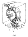
Fig. 1 is an overall perspective schematic view of a laundry washing machine incorporating the apparatus according to the invention; -
Fig. 2 schematically shows the apparatus according to the invention arranged below the tank of a laundry washing machine; -
Fig. 3 is a plan view, partly in section, of a first embodiment of the apparatus according to the invention; -
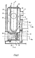
Fig. 4 is a partial sectional view of the apparatus taken along axis X-X of the reservoir; -
Fig. 5 is a partial sectional view of the apparatus taken along line V-V ofFig. 2 ; -
Fig. 6 is a plan view, partly in section, of a second embodiment of the apparatus; -
Fig. 7 is a plan view, partly in section, of a third embodiment of the apparatus. - With particular reference to
Figs. 1 to 5 , the apparatus, in accordance with the invention, comprises areservoir 1 for installation in the laundry washing machine below thetank 2, in which adrum 3 is conventionally arranged so as to be able to rotate and into which the laundry to be washed is placed. - The
reservoir 1, designed to contain at least a substantial portion of the amount of liquid used during washing and/or rinsing operations, depending on the operative phase of the machine, is connected in a conventional manner to thetank 2 via a hydraulic feed connection illustrated by theline 4 shown inFigs. 1 and2 and via a return connection illustrated by theconduit 5. - The
feed connection 4 is directed to thenozzles 4a for feeding liquid into the tank whilst thereturn connection 5 comes from the discharge opening 6 in the base of thetank 2. - The
reservoir 1 has a longitudinal axis X-X which extends between theopposing end walls 7 and 8 and comprises abase wall 9, atop wall 10 andside walls - In accordance with the invention, the apparatus comprises
first pumping elements 13 for circulating liquid from thereservoir 1 to thetank 2 and vice-versa, andsecond pumping elements 14 for discharging liquid from thereservoir 1 and from the machine via an evacuation conduit indicated by thereference numeral 15 inFigs. 2 and3 . - The
pumping elements reference numerals - In accordance with the invention, in the embodiment shown in
Figs. 2 ,3, 4 and 5 , thepumps walls reservoir 1 respectively and communicate with the interior thereof viarespective openings walls reservoir 1. - The central axis of
symmetry 18a of theopening 18 associated with thepump 13 for recirculating liquid inside thetank 2 is perpendicular to the axis X-X of thereservoir 1 and is arranged in the region of the reservoir between said longitudinal axis X-X and thetop wall 10 of thereservoir 1. - The central axis of
symmetry 19a of theopening 19, associated with thepump 14 for discharging and evacuating liquid from thereservoir 1, for example at the end of washing cycles, is also perpendicular to the longitudinal axis X-X of thereservoir 1 and is arranged in a region of the reservoir in such a way that thelower edge 19b of theopening 19 is positioned between the longitudinal axis X-X of the reservoir and thebase wall 9 thereof, remaining, however, higher than the heating means 20 arranged inside thereservoir 1 so as to avoid exposing said heating means at the end of a liquid discharge phase. - In particular, the distance between the
axis 18a of the opening connected to therecirculation pump 13 and theaxis 19a of the opening connected to thedischarge pump 14 is advantageously maintained at approximately 35 mm taking into account that the overall volume of thereservoir 1 must not exceed 600 ml. - Such heating means are conventionally formed by an electrical resistance fed via the
terminals - In accordance with the embodiment of
Figs. 2 ,3, 4 and 5 , the apparatus also comprises filtering elements, indicated as a whole withreference numeral 23, arranged in asocket 24 formed in thereservoir 1 through thewall 8 thereof and accessible from outside theprofile 25 of the laundry washing machine in a conventional manner via acover 26. - The
socket 24 communicates with the interior of thereservoir 1 via theopening 27 and with theconduit 5, coming from thetank 2, via theopening 28. - The
filtering elements 23, however, remain positioned in the hydraulic path coming from thetank 2 before both therecirculation pump 13 and thedischarge pump 14 and mounted on thereservoir 1 with the substantial elimination of external connecting tubes. - The apparatus is completed with a
pressure regulator 29 which is also mounted on thereservoir 1. - With reference to the embodiment shown in
Fig. 6 , in which parts similar or equivalent to those in the embodiment ofFigs. 2 ,3, 4 and 5 have like reference numerals, it can be seen that therecirculation pump 13 and thedischarge pump 14 are mounted on thereservoir 1 on the same wall, in this case on thewall 11. - The
filtering elements 23 are positioned before thedischarge pump 14 and therefore are active only when liquid is discharged from thereservoir 1 and not during recirculation, as is the case in the embodiment ofFigs. 2 ,3, 4 and 5 . - With reference to
Fig. 7 a different positioning of therecirculation 13 anddischarge 14 pumps can be seen, in accordance with which the central axis of the openings in the reservoir connected to the pumps is arranged parallel to the longitudinal axis X-X of thereservoir 1. - As a result of the description above, the apparatus according to the invention is presented as a compact module of interconnected elements with no hydraulic conduits and therefore with a substantial reduction in the volumes which are to be filled with washing and recirculation liquids, with the advantage of savings in the amount of energy consumed by the machine when it is in operation.
Claims (10)
- Apparatus for circulating flows of washing and rinsing liquids in a laundry washing machine of the type comprising a tank (2), a drum (3) for the laundry to be washed arranged so as to be able to rotate inside the tank, a plurality of nozzles (4a) for releasing the liquids into the tank (2) and an opening (6) in the base of the tank (2) for the discharge of said liquids, said apparatus comprising a reservoir (1) arranged beneath the base of the tank (2) and able to hold a predetermined amount of washing or rinsing liquid, said reservoir being hydraulically connected to said nozzles (4a), to said opening (6) in the base of the tank (2) and to an outlet (15) outside the machine and being provided with a longitudinal axis (X-X) which extends between two opposing end walls (7, 8), a base wall (9), a top wall (10) and side walls (11, 12) extending parallel to said longitudinal axis (X-X), first pumping elements (13) for circulating liquids from the reservoir (1) to the tank (2) and vice-versa, second pumping elements (14) for discharging liquids from the reservoir (1) and from the machine, heating means (20) arranged inside the reservoir (1) and elements (23, 24) for filtering liquids circulating in the reservoir (1), characterised in that at least said first (13) and said second (14) pumping elements are fixed directly onto one of the walls of said reservoir (1).
- Apparatus according to claim 1, characterised in that said first (13) and said second (14) pumping elements are both mounted on the same side wall (11) of the reservoir (1).
- Apparatus according to claim 1, characterised in that said first (13) pumping elements are mounted on one (11) of the walls of the reservoir (1) whilst said second pumping elements (14) are mounted on the opposing wall (12) of the reservoir (1).
- Apparatus according to claims 1 to 3, characterised in that said first (13) and said second (14) pumping elements are connected to the interior of said reservoir (1) via openings (18, 19) formed in the respective walls of the reservoir (1), said openings each being provided with a central axis (18a, 19a) arranged perpendicular to said longitudinal axis (X-X) of the reservoir (1).
- Apparatus according to claims 1 to 3, characterised in that said first (13) and said second (14) pumping elements are connected to the interior of said reservoir (1) via openings (18, 19) formed in the respective walls of the reservoir, said openings (18, 19) each being provided with a central axis (18a, 19a) arranged parallel to said longitudinal axis (X-X) of the reservoir (1).
- Apparatus according to either claim 4 or claim 5, characterised in that the central axis (18a) of the opening (18) connected to the first said pumping elements (13) for circulating liquids into and from the tank (2) of the laundry washing machine, is arranged in the region of the reservoir (1) between the longitudinal axis (X-X) of the reservoir and the top wall (10) thereof.
- Apparatus according to either claim 4 or claim 5, characterised in that the central axis (19a) of the opening (19) connected to said second pumping elements (14) for discharging liquids from the reservoir (1) and from the machine is arranged in a region of the reservoir (1) in such a way that the lower edge (19b) of the opening is positioned between the longitudinal axis (X-X) of the reservoir (1) and the base wall (9) thereof, remaining at a level higher than that where said heating means (20) are positioned.
- Apparatus according to claim 1, characterised in that said elements (23, 24) for filtering liquid are positioned on said reservoir (1) and are arranged in the path of fluid issuing from the tank (2) of the machine to the reservoir (1) before said first pumping elements (13).
- Apparatus according to claim 8, characterised in that said elements (23, 24) for filtering liquid are fixed to one (11) of said walls of the reservoir (1) which extend parallel to the longitudinal axis (X-X) thereof.
- Apparatus according to claim 1, characterised in that said elements (23, 24) for filtering liquid are positioned on said reservoir (1) and are fixed on one (8) of said end walls of the reservoir and are arranged in the path of fluid between said reservoir (1) and said second pumping elements (14) for discharging liquids from the reservoir and from the machine.
Priority Applications (3)
| Application Number | Priority Date | Filing Date | Title |
|---|---|---|---|
| DE602008002739T DE602008002739D1 (en) | 2008-06-24 | 2008-06-24 | Device for circulating flows of washing and rinsing liquids in a washing machine |
| ES08425443T ES2352585T3 (en) | 2008-06-24 | 2008-06-24 | APPARATUS FOR CIRCULATING FLOWS OF WASHING AND RINSE LIQUIDS IN A CLOTHING WASHING MACHINE. |
| EP08425443A EP2138625B1 (en) | 2008-06-24 | 2008-06-24 | Apparatus for circulating flows of washing and rinsing liquids in a laundry washing machine |
Applications Claiming Priority (1)
| Application Number | Priority Date | Filing Date | Title |
|---|---|---|---|
| EP08425443A EP2138625B1 (en) | 2008-06-24 | 2008-06-24 | Apparatus for circulating flows of washing and rinsing liquids in a laundry washing machine |
Publications (2)
| Publication Number | Publication Date |
|---|---|
| EP2138625A1 true EP2138625A1 (en) | 2009-12-30 |
| EP2138625B1 EP2138625B1 (en) | 2010-09-22 |
Family
ID=39967252
Family Applications (1)
| Application Number | Title | Priority Date | Filing Date |
|---|---|---|---|
| EP08425443A Active EP2138625B1 (en) | 2008-06-24 | 2008-06-24 | Apparatus for circulating flows of washing and rinsing liquids in a laundry washing machine |
Country Status (3)
| Country | Link |
|---|---|
| EP (1) | EP2138625B1 (en) |
| DE (1) | DE602008002739D1 (en) |
| ES (1) | ES2352585T3 (en) |
Cited By (4)
| Publication number | Priority date | Publication date | Assignee | Title |
|---|---|---|---|---|
| WO2011109371A3 (en) * | 2010-03-01 | 2012-02-23 | Pellerin Milnor Corporation | Washer extractor and method |
| JP2017108780A (en) * | 2015-12-14 | 2017-06-22 | 青島海爾洗衣机有限公司QingDao Haier Washing Machine Co.,Ltd. | Water storage tank and washing machine for washing machine |
| WO2017133825A1 (en) * | 2016-02-01 | 2017-08-10 | BSH Hausgeräte GmbH | Laundry treatment appliance comprising a pump drive system |
| CN109972357A (en) * | 2017-12-28 | 2019-07-05 | Lg电子株式会社 | Washing machine |
Citations (2)
| Publication number | Priority date | Publication date | Assignee | Title |
|---|---|---|---|---|
| US6167733B1 (en) * | 1998-06-30 | 2001-01-02 | Daewoo Electronics Co., Ltd. | Drum type washing machine having a pump integrally formed with a filter |
| US20060000240A1 (en) * | 2004-07-02 | 2006-01-05 | Samsung Electronics Co., Ltd. | Washing machine |
-
2008
- 2008-06-24 DE DE602008002739T patent/DE602008002739D1/en active Active
- 2008-06-24 EP EP08425443A patent/EP2138625B1/en active Active
- 2008-06-24 ES ES08425443T patent/ES2352585T3/en active Active
Patent Citations (2)
| Publication number | Priority date | Publication date | Assignee | Title |
|---|---|---|---|---|
| US6167733B1 (en) * | 1998-06-30 | 2001-01-02 | Daewoo Electronics Co., Ltd. | Drum type washing machine having a pump integrally formed with a filter |
| US20060000240A1 (en) * | 2004-07-02 | 2006-01-05 | Samsung Electronics Co., Ltd. | Washing machine |
Cited By (8)
| Publication number | Priority date | Publication date | Assignee | Title |
|---|---|---|---|---|
| WO2011109371A3 (en) * | 2010-03-01 | 2012-02-23 | Pellerin Milnor Corporation | Washer extractor and method |
| CN102782203A (en) * | 2010-03-01 | 2012-11-14 | 佩莱若林·米尔诺公司 | Washer extractor and method |
| JP2017108780A (en) * | 2015-12-14 | 2017-06-22 | 青島海爾洗衣机有限公司QingDao Haier Washing Machine Co.,Ltd. | Water storage tank and washing machine for washing machine |
| WO2017133825A1 (en) * | 2016-02-01 | 2017-08-10 | BSH Hausgeräte GmbH | Laundry treatment appliance comprising a pump drive system |
| CN108603323A (en) * | 2016-02-01 | 2018-09-28 | Bsh家用电器有限公司 | Washings care appliance with pump driving-controlling device |
| CN109972357A (en) * | 2017-12-28 | 2019-07-05 | Lg电子株式会社 | Washing machine |
| US11499261B2 (en) | 2017-12-28 | 2022-11-15 | Lg Electronics Inc. | Washing machine |
| US11866871B2 (en) | 2017-12-28 | 2024-01-09 | Lg Electronics Inc. | Washing machine |
Also Published As
| Publication number | Publication date |
|---|---|
| EP2138625B1 (en) | 2010-09-22 |
| ES2352585T3 (en) | 2011-02-21 |
| DE602008002739D1 (en) | 2010-11-04 |
Similar Documents
| Publication | Publication Date | Title |
|---|---|---|
| JP5799199B2 (en) | Drum washing machine | |
| EP2138625A1 (en) | Apparatus for circulating flows of washing and rinsing liquids in a laundry washing machine | |
| JP7580437B2 (en) | LAUNDRY AGENT STORAGE CONTAINER AND ITS MANUFACTURING METHOD, AND LAUNDRY AGENT SUPPLY DEVICE EQUIPPED WITH LAUNDRY AGENT STORAGE CONTAINER | |
| CN101652513A (en) | Washing machine and method of controlling the washing machine | |
| CN112030477B (en) | laundry treatment device | |
| EP3639722A1 (en) | Dishwashers having a heat exchanger | |
| CN109881443B (en) | Clothes treating apparatus | |
| EP0382692A1 (en) | Drain device for a dish-washer | |
| EP4276234A1 (en) | Dispenser box, detergent dispensing apparatus, washing device, and washing device kit | |
| EP2138626B1 (en) | Device for releasing washing and / or rinsing liquid into the rotating drum of a laundry washing machine | |
| CN112575542A (en) | Automatic feeding system of washing machine and control method | |
| CN213507652U (en) | Dispensing system and washing machine | |
| US7713358B2 (en) | Dishwashing machine with a gradual-start wash cycle | |
| CN214529790U (en) | Household appliance | |
| CN214529792U (en) | Household appliance | |
| CN214529791U (en) | Household appliance | |
| JP5884012B2 (en) | Washing machine | |
| CN115029899B (en) | Household electrical appliances | |
| ITMI20081148A1 (en) | EQUIPMENT FOR THE CIRCULATION OF THE WASH AND FLUSH LIQUIDS FLOWS IN A MACHINE WASHING MACHINE | |
| CN213835970U (en) | Washing machine with integrated electric control box | |
| CN107663749B (en) | Automatic throwing system of washing machine and washing machine with same | |
| CN214529787U (en) | Home Appliances | |
| CN213835969U (en) | Washing machine with novel water inlet pipeline | |
| CN118147874B (en) | Wall-mounted clothes treatment equipment and control method | |
| CN217261861U (en) | Liquid dispenser |
Legal Events
| Date | Code | Title | Description |
|---|---|---|---|
| PUAI | Public reference made under article 153(3) epc to a published international application that has entered the european phase |
Free format text: ORIGINAL CODE: 0009012 |
|
| 17P | Request for examination filed |
Effective date: 20090227 |
|
| AK | Designated contracting states |
Kind code of ref document: A1 Designated state(s): AT BE BG CH CY CZ DE DK EE ES FI FR GB GR HR HU IE IS IT LI LT LU LV MC MT NL NO PL PT RO SE SI SK TR |
|
| AX | Request for extension of the european patent |
Extension state: AL BA MK RS |
|
| GRAP | Despatch of communication of intention to grant a patent |
Free format text: ORIGINAL CODE: EPIDOSNIGR1 |
|
| GRAS | Grant fee paid |
Free format text: ORIGINAL CODE: EPIDOSNIGR3 |
|
| GRAA | (expected) grant |
Free format text: ORIGINAL CODE: 0009210 |
|
| AKX | Designation fees paid |
Designated state(s): DE ES FR GB IT TR |
|
| AK | Designated contracting states |
Kind code of ref document: B1 Designated state(s): DE ES FR GB IT TR |
|
| REG | Reference to a national code |
Ref country code: GB Ref legal event code: FG4D |
|
| REF | Corresponds to: |
Ref document number: 602008002739 Country of ref document: DE Date of ref document: 20101104 Kind code of ref document: P |
|
| REG | Reference to a national code |
Ref country code: ES Ref legal event code: FG2A Effective date: 20110209 |
|
| PLBI | Opposition filed |
Free format text: ORIGINAL CODE: 0009260 |
|
| PLAI | Examination of admissibility of opposition: information related to despatch of communication + time limit modified |
Free format text: ORIGINAL CODE: EPIDOSCOPE2 |
|
| PLAZ | Examination of admissibility of opposition: despatch of communication + time limit |
Free format text: ORIGINAL CODE: EPIDOSNOPE2 |
|
| 26 | Opposition filed |
Opponent name: MARTINEZ, GEORGES Effective date: 20110323 |
|
| REG | Reference to a national code |
Ref country code: DE Ref legal event code: R026 Ref document number: 602008002739 Country of ref document: DE Effective date: 20110323 |
|
| PLBA | Examination of admissibility of opposition: reply received |
Free format text: ORIGINAL CODE: EPIDOSNOPE4 |
|
| PLAX | Notice of opposition and request to file observation + time limit sent |
Free format text: ORIGINAL CODE: EPIDOSNOBS2 |
|
| PLBB | Reply of patent proprietor to notice(s) of opposition received |
Free format text: ORIGINAL CODE: EPIDOSNOBS3 |
|
| PLCK | Communication despatched that opposition was rejected |
Free format text: ORIGINAL CODE: EPIDOSNREJ1 |
|
| APAH | Appeal reference modified |
Free format text: ORIGINAL CODE: EPIDOSCREFNO |
|
| APBM | Appeal reference recorded |
Free format text: ORIGINAL CODE: EPIDOSNREFNO |
|
| APBP | Date of receipt of notice of appeal recorded |
Free format text: ORIGINAL CODE: EPIDOSNNOA2O |
|
| APBQ | Date of receipt of statement of grounds of appeal recorded |
Free format text: ORIGINAL CODE: EPIDOSNNOA3O |
|
| REG | Reference to a national code |
Ref country code: DE Ref legal event code: R100 Ref document number: 602008002739 Country of ref document: DE |
|
| APBU | Appeal procedure closed |
Free format text: ORIGINAL CODE: EPIDOSNNOA9O |
|
| PLBN | Opposition rejected |
Free format text: ORIGINAL CODE: 0009273 |
|
| STAA | Information on the status of an ep patent application or granted ep patent |
Free format text: STATUS: OPPOSITION REJECTED |
|
| 27O | Opposition rejected |
Effective date: 20131210 |
|
| POAG | Date of filing of petition for review recorded |
Free format text: ORIGINAL CODE: EPIDOSNPRV3 |
|
| POAH | Number of petition for review recorded |
Free format text: ORIGINAL CODE: EPIDOSNPRV1 |
|
| POAI | Petitioner in petition for review recorded |
Free format text: ORIGINAL CODE: EPIDOSNPRV2 |
|
| POAK | Decision taken: petition for review obviously unsubstantiated |
Free format text: ORIGINAL CODE: 0009255 |
|
| REG | Reference to a national code |
Ref country code: DE Ref legal event code: R100 Ref document number: 602008002739 Country of ref document: DE Effective date: 20131210 |
|
| PRVN | Petition for review not allowed |
Free format text: PETITION FOR REVIEW OBVIOUSLY UNSUBSTANTIATED Effective date: 20150304 |
|
| REG | Reference to a national code |
Ref country code: FR Ref legal event code: PLFP Year of fee payment: 9 |
|
| REG | Reference to a national code |
Ref country code: FR Ref legal event code: PLFP Year of fee payment: 10 |
|
| REG | Reference to a national code |
Ref country code: FR Ref legal event code: PLFP Year of fee payment: 11 |
|
| REG | Reference to a national code |
Ref country code: DE Ref legal event code: R082 Ref document number: 602008002739 Country of ref document: DE Representative=s name: MEISSNER BOLTE PATENTANWAELTE RECHTSANWAELTE P, DE |
|
| PGFP | Annual fee paid to national office [announced via postgrant information from national office to epo] |
Ref country code: IT Payment date: 20230419 Year of fee payment: 16 Ref country code: FR Payment date: 20230622 Year of fee payment: 16 Ref country code: DE Payment date: 20230620 Year of fee payment: 16 |
|
| PGFP | Annual fee paid to national office [announced via postgrant information from national office to epo] |
Ref country code: TR Payment date: 20230619 Year of fee payment: 16 |
|
| PGFP | Annual fee paid to national office [announced via postgrant information from national office to epo] |
Ref country code: GB Payment date: 20230620 Year of fee payment: 16 Ref country code: ES Payment date: 20230703 Year of fee payment: 16 |
|
| REG | Reference to a national code |
Ref country code: DE Ref legal event code: R119 Ref document number: 602008002739 Country of ref document: DE |
|
| GBPC | Gb: european patent ceased through non-payment of renewal fee |
Effective date: 20240624 |
|
| PG25 | Lapsed in a contracting state [announced via postgrant information from national office to epo] |
Ref country code: DE Free format text: LAPSE BECAUSE OF NON-PAYMENT OF DUE FEES Effective date: 20250101 |
|
| PG25 | Lapsed in a contracting state [announced via postgrant information from national office to epo] |
Ref country code: FR Free format text: LAPSE BECAUSE OF NON-PAYMENT OF DUE FEES Effective date: 20240630 |
|
| PG25 | Lapsed in a contracting state [announced via postgrant information from national office to epo] |
Ref country code: GB Free format text: LAPSE BECAUSE OF NON-PAYMENT OF DUE FEES Effective date: 20240624 Ref country code: IT Free format text: LAPSE BECAUSE OF NON-PAYMENT OF DUE FEES Effective date: 20240624 |
|
| REG | Reference to a national code |
Ref country code: ES Ref legal event code: FD2A Effective date: 20250801 |
|
| PG25 | Lapsed in a contracting state [announced via postgrant information from national office to epo] |
Ref country code: ES Free format text: LAPSE BECAUSE OF NON-PAYMENT OF DUE FEES Effective date: 20240625 |