EP2138557A1 - An upper internal combustion engine cleaning composition - Google Patents
An upper internal combustion engine cleaning composition Download PDFInfo
- Publication number
- EP2138557A1 EP2138557A1 EP08015093A EP08015093A EP2138557A1 EP 2138557 A1 EP2138557 A1 EP 2138557A1 EP 08015093 A EP08015093 A EP 08015093A EP 08015093 A EP08015093 A EP 08015093A EP 2138557 A1 EP2138557 A1 EP 2138557A1
- Authority
- EP
- European Patent Office
- Prior art keywords
- cleaning composition
- upper engine
- engine cleaning
- dielectric constant
- engine
- Prior art date
- Legal status (The legal status is an assumption and is not a legal conclusion. Google has not performed a legal analysis and makes no representation as to the accuracy of the status listed.)
- Withdrawn
Links
- 239000000203 mixture Substances 0.000 title claims abstract description 52
- 238000002485 combustion reaction Methods 0.000 title claims abstract description 20
- 238000004140 cleaning Methods 0.000 title claims description 34
- 239000002904 solvent Substances 0.000 claims abstract description 10
- 239000000010 aprotic solvent Substances 0.000 claims abstract description 5
- 238000002844 melting Methods 0.000 claims abstract 2
- 230000008018 melting Effects 0.000 claims abstract 2
- XLYOFNOQVPJJNP-UHFFFAOYSA-N water Substances O XLYOFNOQVPJJNP-UHFFFAOYSA-N 0.000 claims description 52
- ATHHXGZTWNVVOU-UHFFFAOYSA-N N-methylformamide Chemical compound CNC=O ATHHXGZTWNVVOU-UHFFFAOYSA-N 0.000 claims description 48
- OKKJLVBELUTLKV-UHFFFAOYSA-N Methanol Chemical compound OC OKKJLVBELUTLKV-UHFFFAOYSA-N 0.000 claims description 27
- 239000007921 spray Substances 0.000 claims description 24
- LYCAIKOWRPUZTN-UHFFFAOYSA-N Ethylene glycol Chemical compound OCCO LYCAIKOWRPUZTN-UHFFFAOYSA-N 0.000 claims description 21
- ZHNUHDYFZUAESO-UHFFFAOYSA-N Formamide Chemical compound NC=O ZHNUHDYFZUAESO-UHFFFAOYSA-N 0.000 claims description 18
- WEVYAHXRMPXWCK-UHFFFAOYSA-N Acetonitrile Chemical compound CC#N WEVYAHXRMPXWCK-UHFFFAOYSA-N 0.000 claims description 15
- LCGLNKUTAGEVQW-UHFFFAOYSA-N Dimethyl ether Chemical compound COC LCGLNKUTAGEVQW-UHFFFAOYSA-N 0.000 claims description 15
- OAKJQQAXSVQMHS-UHFFFAOYSA-N Hydrazine Chemical compound NN OAKJQQAXSVQMHS-UHFFFAOYSA-N 0.000 claims description 14
- 238000000034 method Methods 0.000 claims description 13
- 230000002195 synergetic effect Effects 0.000 claims description 12
- KFZMGEQAYNKOFK-UHFFFAOYSA-N Isopropanol Chemical compound CC(C)O KFZMGEQAYNKOFK-UHFFFAOYSA-N 0.000 claims description 11
- 239000003380 propellant Substances 0.000 claims description 11
- CSCPPACGZOOCGX-UHFFFAOYSA-N Acetone Chemical compound CC(C)=O CSCPPACGZOOCGX-UHFFFAOYSA-N 0.000 claims description 10
- IAZDPXIOMUYVGZ-UHFFFAOYSA-N Dimethylsulphoxide Chemical compound CS(C)=O IAZDPXIOMUYVGZ-UHFFFAOYSA-N 0.000 claims description 10
- ZMXDDKWLCZADIW-UHFFFAOYSA-N N,N-Dimethylformamide Chemical compound CN(C)C=O ZMXDDKWLCZADIW-UHFFFAOYSA-N 0.000 claims description 9
- 239000004479 aerosol dispenser Substances 0.000 claims description 9
- PEDCQBHIVMGVHV-UHFFFAOYSA-N Glycerine Chemical compound OCC(O)CO PEDCQBHIVMGVHV-UHFFFAOYSA-N 0.000 claims description 8
- -1 nitrogen- containing compound Chemical class 0.000 claims description 8
- VHUUQVKOLVNVRT-UHFFFAOYSA-N Ammonium hydroxide Chemical compound [NH4+].[OH-] VHUUQVKOLVNVRT-UHFFFAOYSA-N 0.000 claims description 6
- 239000000908 ammonium hydroxide Substances 0.000 claims description 6
- 229930195733 hydrocarbon Natural products 0.000 claims description 6
- 150000002430 hydrocarbons Chemical class 0.000 claims description 5
- 230000008569 process Effects 0.000 claims description 5
- ZFPGARUNNKGOBB-UHFFFAOYSA-N 1-Ethyl-2-pyrrolidinone Chemical compound CCN1CCCC1=O ZFPGARUNNKGOBB-UHFFFAOYSA-N 0.000 claims description 4
- 239000004215 Carbon black (E152) Substances 0.000 claims description 4
- LFQSCWFLJHTTHZ-UHFFFAOYSA-N Ethanol Chemical compound CCO LFQSCWFLJHTTHZ-UHFFFAOYSA-N 0.000 claims description 4
- 235000011187 glycerol Nutrition 0.000 claims description 4
- GNOIPBMMFNIUFM-UHFFFAOYSA-N hexamethylphosphoric triamide Chemical compound CN(C)P(=O)(N(C)C)N(C)C GNOIPBMMFNIUFM-UHFFFAOYSA-N 0.000 claims description 4
- FXHOOIRPVKKKFG-UHFFFAOYSA-N N,N-Dimethylacetamide Chemical compound CN(C)C(C)=O FXHOOIRPVKKKFG-UHFFFAOYSA-N 0.000 claims description 3
- LYGJENNIWJXYER-UHFFFAOYSA-N nitromethane Chemical compound C[N+]([O-])=O LYGJENNIWJXYER-UHFFFAOYSA-N 0.000 claims description 3
- 150000003335 secondary amines Chemical class 0.000 claims description 3
- 150000003512 tertiary amines Chemical class 0.000 claims description 3
- 150000003973 alkyl amines Chemical group 0.000 claims description 2
- 150000001875 compounds Chemical class 0.000 claims description 2
- 239000002245 particle Substances 0.000 claims description 2
- 125000002924 primary amino group Chemical group [H]N([H])* 0.000 claims description 2
- 235000011114 ammonium hydroxide Nutrition 0.000 claims 5
- VQTUBCCKSQIDNK-UHFFFAOYSA-N Isobutene Chemical compound CC(C)=C VQTUBCCKSQIDNK-UHFFFAOYSA-N 0.000 claims 4
- ATUOYWHBWRKTHZ-UHFFFAOYSA-N Propane Chemical compound CCC ATUOYWHBWRKTHZ-UHFFFAOYSA-N 0.000 claims 4
- NPNPZTNLOVBDOC-UHFFFAOYSA-N 1,1-difluoroethane Chemical compound CC(F)F NPNPZTNLOVBDOC-UHFFFAOYSA-N 0.000 claims 2
- XKRFYHLGVUSROY-UHFFFAOYSA-N Argon Chemical compound [Ar] XKRFYHLGVUSROY-UHFFFAOYSA-N 0.000 claims 2
- IJGRMHOSHXDMSA-UHFFFAOYSA-N Atomic nitrogen Chemical compound N#N IJGRMHOSHXDMSA-UHFFFAOYSA-N 0.000 claims 2
- XXROGKLTLUQVRX-UHFFFAOYSA-N allyl alcohol Chemical compound OCC=C XXROGKLTLUQVRX-UHFFFAOYSA-N 0.000 claims 2
- UHCBBWUQDAVSMS-UHFFFAOYSA-N fluoroethane Chemical compound CCF UHCBBWUQDAVSMS-UHFFFAOYSA-N 0.000 claims 2
- NBVXSUQYWXRMNV-UHFFFAOYSA-N fluoromethane Chemical compound FC NBVXSUQYWXRMNV-UHFFFAOYSA-N 0.000 claims 2
- UMFJAHHVKNCGLG-UHFFFAOYSA-N n-Nitrosodimethylamine Chemical compound CN(C)N=O UMFJAHHVKNCGLG-UHFFFAOYSA-N 0.000 claims 2
- 239000001294 propane Substances 0.000 claims 2
- 125000001453 quaternary ammonium group Chemical group 0.000 claims 2
- GQPLMRYTRLFLPF-UHFFFAOYSA-N Nitrous Oxide Chemical compound [O-][N+]#N GQPLMRYTRLFLPF-UHFFFAOYSA-N 0.000 claims 1
- 239000003570 air Substances 0.000 claims 1
- 229910052786 argon Inorganic materials 0.000 claims 1
- 229940113088 dimethylacetamide Drugs 0.000 claims 1
- ZZUFCTLCJUWOSV-UHFFFAOYSA-N furosemide Chemical compound C1=C(Cl)C(S(=O)(=O)N)=CC(C(O)=O)=C1NCC1=CC=CO1 ZZUFCTLCJUWOSV-UHFFFAOYSA-N 0.000 claims 1
- IJDNQMDRQITEOD-UHFFFAOYSA-N n-butane Chemical compound CCCC IJDNQMDRQITEOD-UHFFFAOYSA-N 0.000 claims 1
- 229910052757 nitrogen Inorganic materials 0.000 claims 1
- 150000003141 primary amines Chemical class 0.000 claims 1
- 238000012360 testing method Methods 0.000 abstract description 22
- 239000000443 aerosol Substances 0.000 abstract description 19
- JJWLVOIRVHMVIS-UHFFFAOYSA-N isopropylamine Chemical compound CC(C)N JJWLVOIRVHMVIS-UHFFFAOYSA-N 0.000 description 35
- 239000008367 deionised water Substances 0.000 description 16
- 239000000446 fuel Substances 0.000 description 14
- 229910021641 deionized water Inorganic materials 0.000 description 12
- 239000000047 product Substances 0.000 description 10
- ZMANZCXQSJIPKH-UHFFFAOYSA-N Triethylamine Chemical compound CCN(CC)CC ZMANZCXQSJIPKH-UHFFFAOYSA-N 0.000 description 9
- KDSNLYIMUZNERS-UHFFFAOYSA-N 2-methylpropanamine Chemical compound CC(C)CN KDSNLYIMUZNERS-UHFFFAOYSA-N 0.000 description 8
- YNAVUWVOSKDBBP-UHFFFAOYSA-N Morpholine Chemical compound C1COCCN1 YNAVUWVOSKDBBP-UHFFFAOYSA-N 0.000 description 8
- 239000003595 mist Substances 0.000 description 8
- 239000000126 substance Substances 0.000 description 8
- VVJKKWFAADXIJK-UHFFFAOYSA-N Allylamine Chemical compound NCC=C VVJKKWFAADXIJK-UHFFFAOYSA-N 0.000 description 6
- RWRDLPDLKQPQOW-UHFFFAOYSA-N Pyrrolidine Chemical compound C1CCNC1 RWRDLPDLKQPQOW-UHFFFAOYSA-N 0.000 description 6
- WQDUMFSSJAZKTM-UHFFFAOYSA-N Sodium methoxide Chemical compound [Na+].[O-]C WQDUMFSSJAZKTM-UHFFFAOYSA-N 0.000 description 6
- HQABUPZFAYXKJW-UHFFFAOYSA-N butan-1-amine Chemical compound CCCCN HQABUPZFAYXKJW-UHFFFAOYSA-N 0.000 description 6
- 239000007788 liquid Substances 0.000 description 6
- 239000012085 test solution Substances 0.000 description 6
- 238000007906 compression Methods 0.000 description 5
- 230000006835 compression Effects 0.000 description 5
- 239000012530 fluid Substances 0.000 description 5
- JSHASCFKOSDFHY-UHFFFAOYSA-N 1-butylpyrrolidine Chemical compound CCCCN1CCCC1 JSHASCFKOSDFHY-UHFFFAOYSA-N 0.000 description 4
- HZAXFHJVJLSVMW-UHFFFAOYSA-N 2-Aminoethan-1-ol Chemical compound NCCO HZAXFHJVJLSVMW-UHFFFAOYSA-N 0.000 description 4
- PAFZNILMFXTMIY-UHFFFAOYSA-N cyclohexylamine Chemical compound NC1CCCCC1 PAFZNILMFXTMIY-UHFFFAOYSA-N 0.000 description 4
- 238000012423 maintenance Methods 0.000 description 4
- 239000000243 solution Substances 0.000 description 4
- WDQFELCEOPFLCZ-UHFFFAOYSA-N 1-(2-hydroxyethyl)pyrrolidin-2-one Chemical compound OCCN1CCCC1=O WDQFELCEOPFLCZ-UHFFFAOYSA-N 0.000 description 3
- OXHNLMTVIGZXSG-UHFFFAOYSA-N 1-Methylpyrrole Chemical compound CN1C=CC=C1 OXHNLMTVIGZXSG-UHFFFAOYSA-N 0.000 description 3
- CBENFWSGALASAD-UHFFFAOYSA-N Ozone Chemical compound [O-][O+]=O CBENFWSGALASAD-UHFFFAOYSA-N 0.000 description 3
- HEMHJVSKTPXQMS-UHFFFAOYSA-M Sodium hydroxide Chemical compound [OH-].[Na+] HEMHJVSKTPXQMS-UHFFFAOYSA-M 0.000 description 3
- HPNMFZURTQLUMO-UHFFFAOYSA-N diethylamine Chemical compound CCNCC HPNMFZURTQLUMO-UHFFFAOYSA-N 0.000 description 3
- 230000000694 effects Effects 0.000 description 3
- 238000009472 formulation Methods 0.000 description 3
- YNOGYQAEJGADFJ-UHFFFAOYSA-N oxolan-2-ylmethanamine Chemical compound NCC1CCCO1 YNOGYQAEJGADFJ-UHFFFAOYSA-N 0.000 description 3
- HNJBEVLQSNELDL-UHFFFAOYSA-N pyrrolidin-2-one Chemical compound O=C1CCCN1 HNJBEVLQSNELDL-UHFFFAOYSA-N 0.000 description 3
- HXJUTPCZVOIRIF-UHFFFAOYSA-N sulfolane Chemical compound O=S1(=O)CCCC1 HXJUTPCZVOIRIF-UHFFFAOYSA-N 0.000 description 3
- YBRBMKDOPFTVDT-UHFFFAOYSA-N tert-butylamine Chemical compound CC(C)(C)N YBRBMKDOPFTVDT-UHFFFAOYSA-N 0.000 description 3
- 239000012855 volatile organic compound Substances 0.000 description 3
- HXKKHQJGJAFBHI-UHFFFAOYSA-N 1-aminopropan-2-ol Chemical compound CC(O)CN HXKKHQJGJAFBHI-UHFFFAOYSA-N 0.000 description 2
- AVFZOVWCLRSYKC-UHFFFAOYSA-N 1-methylpyrrolidine Chemical compound CN1CCCC1 AVFZOVWCLRSYKC-UHFFFAOYSA-N 0.000 description 2
- DLFVBJFMPXGRIB-UHFFFAOYSA-N Acetamide Chemical compound CC(N)=O DLFVBJFMPXGRIB-UHFFFAOYSA-N 0.000 description 2
- QGZKDVFQNNGYKY-UHFFFAOYSA-N Ammonia Chemical compound N QGZKDVFQNNGYKY-UHFFFAOYSA-N 0.000 description 2
- WPPOGHDFAVQKLN-UHFFFAOYSA-N N-Octyl-2-pyrrolidone Chemical compound CCCCCCCCN1CCCC1=O WPPOGHDFAVQKLN-UHFFFAOYSA-N 0.000 description 2
- AHVYPIQETPWLSZ-UHFFFAOYSA-N N-methyl-pyrrolidine Natural products CN1CC=CC1 AHVYPIQETPWLSZ-UHFFFAOYSA-N 0.000 description 2
- WUGQZFFCHPXWKQ-UHFFFAOYSA-N Propanolamine Chemical compound NCCCO WUGQZFFCHPXWKQ-UHFFFAOYSA-N 0.000 description 2
- 230000009471 action Effects 0.000 description 2
- 238000013019 agitation Methods 0.000 description 2
- QVGXLLKOCUKJST-UHFFFAOYSA-N atomic oxygen Chemical compound [O] QVGXLLKOCUKJST-UHFFFAOYSA-N 0.000 description 2
- 230000003197 catalytic effect Effects 0.000 description 2
- 238000011156 evaluation Methods 0.000 description 2
- 238000002474 experimental method Methods 0.000 description 2
- 238000011049 filling Methods 0.000 description 2
- 239000012634 fragment Substances 0.000 description 2
- HYBBIBNJHNGZAN-UHFFFAOYSA-N furfural Chemical compound O=CC1=CC=CO1 HYBBIBNJHNGZAN-UHFFFAOYSA-N 0.000 description 2
- DDRPCXLAQZKBJP-UHFFFAOYSA-N furfurylamine Chemical compound NCC1=CC=CO1 DDRPCXLAQZKBJP-UHFFFAOYSA-N 0.000 description 2
- 230000006872 improvement Effects 0.000 description 2
- 229910052760 oxygen Inorganic materials 0.000 description 2
- 239000001301 oxygen Substances 0.000 description 2
- 238000012546 transfer Methods 0.000 description 2
- 239000002966 varnish Substances 0.000 description 2
- KJLPSBMDOIVXSN-UHFFFAOYSA-N 4-[4-[2-[4-(3,4-dicarboxyphenoxy)phenyl]propan-2-yl]phenoxy]phthalic acid Chemical compound C=1C=C(OC=2C=C(C(C(O)=O)=CC=2)C(O)=O)C=CC=1C(C)(C)C(C=C1)=CC=C1OC1=CC=C(C(O)=O)C(C(O)=O)=C1 KJLPSBMDOIVXSN-UHFFFAOYSA-N 0.000 description 1
- 229910001369 Brass Inorganic materials 0.000 description 1
- 0 CCCC(C1)C1(*CC)C1CC(CC)*C1 Chemical compound CCCC(C1)C1(*CC)C1CC(CC)*C1 0.000 description 1
- OKTJSMMVPCPJKN-UHFFFAOYSA-N Carbon Chemical compound [C] OKTJSMMVPCPJKN-UHFFFAOYSA-N 0.000 description 1
- 206010016275 Fear Diseases 0.000 description 1
- XSTXAVWGXDQKEL-UHFFFAOYSA-N Trichloroethylene Chemical group ClC=C(Cl)Cl XSTXAVWGXDQKEL-UHFFFAOYSA-N 0.000 description 1
- 241000722921 Tulipa gesneriana Species 0.000 description 1
- 239000000654 additive Substances 0.000 description 1
- 150000008044 alkali metal hydroxides Chemical class 0.000 description 1
- 229910052782 aluminium Inorganic materials 0.000 description 1
- XAGFODPZIPBFFR-UHFFFAOYSA-N aluminium Chemical compound [Al] XAGFODPZIPBFFR-UHFFFAOYSA-N 0.000 description 1
- 229910021529 ammonia Inorganic materials 0.000 description 1
- 239000002585 base Substances 0.000 description 1
- 238000005452 bending Methods 0.000 description 1
- 230000008901 benefit Effects 0.000 description 1
- 230000033228 biological regulation Effects 0.000 description 1
- 238000009835 boiling Methods 0.000 description 1
- 239000010951 brass Substances 0.000 description 1
- 229910052799 carbon Inorganic materials 0.000 description 1
- 230000003749 cleanliness Effects 0.000 description 1
- 239000003086 colorant Substances 0.000 description 1
- 238000004737 colorimetric analysis Methods 0.000 description 1
- 238000004590 computer program Methods 0.000 description 1
- 239000012141 concentrate Substances 0.000 description 1
- 239000000356 contaminant Substances 0.000 description 1
- 238000005336 cracking Methods 0.000 description 1
- 238000002788 crimping Methods 0.000 description 1
- 230000003247 decreasing effect Effects 0.000 description 1
- 238000000151 deposition Methods 0.000 description 1
- 230000008021 deposition Effects 0.000 description 1
- 230000000994 depressogenic effect Effects 0.000 description 1
- 238000011161 development Methods 0.000 description 1
- 238000007865 diluting Methods 0.000 description 1
- 238000010790 dilution Methods 0.000 description 1
- 239000012895 dilution Substances 0.000 description 1
- 238000007599 discharging Methods 0.000 description 1
- 238000005530 etching Methods 0.000 description 1
- 235000019441 ethanol Nutrition 0.000 description 1
- 238000001704 evaporation Methods 0.000 description 1
- 230000008020 evaporation Effects 0.000 description 1
- 239000003517 fume Substances 0.000 description 1
- 239000011521 glass Substances 0.000 description 1
- 238000007654 immersion Methods 0.000 description 1
- 239000004615 ingredient Substances 0.000 description 1
- 238000002347 injection Methods 0.000 description 1
- 239000007924 injection Substances 0.000 description 1
- 230000000266 injurious effect Effects 0.000 description 1
- 238000009533 lab test Methods 0.000 description 1
- 239000012263 liquid product Substances 0.000 description 1
- 229910052751 metal Inorganic materials 0.000 description 1
- 239000002184 metal Substances 0.000 description 1
- WCYWZMWISLQXQU-UHFFFAOYSA-N methyl Chemical class [CH3] WCYWZMWISLQXQU-UHFFFAOYSA-N 0.000 description 1
- 238000002156 mixing Methods 0.000 description 1
- 230000001473 noxious effect Effects 0.000 description 1
- 230000000737 periodic effect Effects 0.000 description 1
- 238000005504 petroleum refining Methods 0.000 description 1
- 239000004033 plastic Substances 0.000 description 1
- 238000001556 precipitation Methods 0.000 description 1
- 238000003825 pressing Methods 0.000 description 1
- 230000009467 reduction Effects 0.000 description 1
- 230000001105 regulatory effect Effects 0.000 description 1
- 238000005067 remediation Methods 0.000 description 1
- 238000011160 research Methods 0.000 description 1
- 230000004044 response Effects 0.000 description 1
- 238000012216 screening Methods 0.000 description 1
- 238000004088 simulation Methods 0.000 description 1
- 239000010802 sludge Substances 0.000 description 1
- 238000002791 soaking Methods 0.000 description 1
- 239000002689 soil Substances 0.000 description 1
- 239000007787 solid Substances 0.000 description 1
- 239000011877 solvent mixture Substances 0.000 description 1
- 238000005507 spraying Methods 0.000 description 1
- 238000003756 stirring Methods 0.000 description 1
- 208000011580 syndromic disease Diseases 0.000 description 1
- 238000010998 test method Methods 0.000 description 1
- UBOXGVDOUJQMTN-UHFFFAOYSA-N trichloroethylene Natural products ClCC(Cl)Cl UBOXGVDOUJQMTN-UHFFFAOYSA-N 0.000 description 1
- 239000005436 troposphere Substances 0.000 description 1
- 229930195735 unsaturated hydrocarbon Natural products 0.000 description 1
- 238000010792 warming Methods 0.000 description 1
Images


Classifications
-
- C—CHEMISTRY; METALLURGY
- C10—PETROLEUM, GAS OR COKE INDUSTRIES; TECHNICAL GASES CONTAINING CARBON MONOXIDE; FUELS; LUBRICANTS; PEAT
- C10L—FUELS NOT OTHERWISE PROVIDED FOR; NATURAL GAS; SYNTHETIC NATURAL GAS OBTAINED BY PROCESSES NOT COVERED BY SUBCLASSES C10G, C10K; LIQUEFIED PETROLEUM GAS; ADDING MATERIALS TO FUELS OR FIRES TO REDUCE SMOKE OR UNDESIRABLE DEPOSITS OR TO FACILITATE SOOT REMOVAL; FIRELIGHTERS
- C10L10/00—Use of additives to fuels or fires for particular purposes
- C10L10/06—Use of additives to fuels or fires for particular purposes for facilitating soot removal
-
- C—CHEMISTRY; METALLURGY
- C11—ANIMAL OR VEGETABLE OILS, FATS, FATTY SUBSTANCES OR WAXES; FATTY ACIDS THEREFROM; DETERGENTS; CANDLES
- C11D—DETERGENT COMPOSITIONS; USE OF SINGLE SUBSTANCES AS DETERGENTS; SOAP OR SOAP-MAKING; RESIN SOAPS; RECOVERY OF GLYCEROL
- C11D17/00—Detergent materials or soaps characterised by their shape or physical properties
- C11D17/0043—For use with aerosol devices
-
- C—CHEMISTRY; METALLURGY
- C11—ANIMAL OR VEGETABLE OILS, FATS, FATTY SUBSTANCES OR WAXES; FATTY ACIDS THEREFROM; DETERGENTS; CANDLES
- C11D—DETERGENT COMPOSITIONS; USE OF SINGLE SUBSTANCES AS DETERGENTS; SOAP OR SOAP-MAKING; RESIN SOAPS; RECOVERY OF GLYCEROL
- C11D7/00—Compositions of detergents based essentially on non-surface-active compounds
- C11D7/02—Inorganic compounds
- C11D7/04—Water-soluble compounds
- C11D7/06—Hydroxides
-
- C—CHEMISTRY; METALLURGY
- C11—ANIMAL OR VEGETABLE OILS, FATS, FATTY SUBSTANCES OR WAXES; FATTY ACIDS THEREFROM; DETERGENTS; CANDLES
- C11D—DETERGENT COMPOSITIONS; USE OF SINGLE SUBSTANCES AS DETERGENTS; SOAP OR SOAP-MAKING; RESIN SOAPS; RECOVERY OF GLYCEROL
- C11D7/00—Compositions of detergents based essentially on non-surface-active compounds
- C11D7/22—Organic compounds
- C11D7/26—Organic compounds containing oxygen
- C11D7/261—Alcohols; Phenols
-
- C—CHEMISTRY; METALLURGY
- C11—ANIMAL OR VEGETABLE OILS, FATS, FATTY SUBSTANCES OR WAXES; FATTY ACIDS THEREFROM; DETERGENTS; CANDLES
- C11D—DETERGENT COMPOSITIONS; USE OF SINGLE SUBSTANCES AS DETERGENTS; SOAP OR SOAP-MAKING; RESIN SOAPS; RECOVERY OF GLYCEROL
- C11D7/00—Compositions of detergents based essentially on non-surface-active compounds
- C11D7/22—Organic compounds
- C11D7/26—Organic compounds containing oxygen
- C11D7/264—Aldehydes; Ketones; Acetals or ketals
-
- C—CHEMISTRY; METALLURGY
- C11—ANIMAL OR VEGETABLE OILS, FATS, FATTY SUBSTANCES OR WAXES; FATTY ACIDS THEREFROM; DETERGENTS; CANDLES
- C11D—DETERGENT COMPOSITIONS; USE OF SINGLE SUBSTANCES AS DETERGENTS; SOAP OR SOAP-MAKING; RESIN SOAPS; RECOVERY OF GLYCEROL
- C11D7/00—Compositions of detergents based essentially on non-surface-active compounds
- C11D7/22—Organic compounds
- C11D7/32—Organic compounds containing nitrogen
- C11D7/3263—Amides or imides
-
- C—CHEMISTRY; METALLURGY
- C11—ANIMAL OR VEGETABLE OILS, FATS, FATTY SUBSTANCES OR WAXES; FATTY ACIDS THEREFROM; DETERGENTS; CANDLES
- C11D—DETERGENT COMPOSITIONS; USE OF SINGLE SUBSTANCES AS DETERGENTS; SOAP OR SOAP-MAKING; RESIN SOAPS; RECOVERY OF GLYCEROL
- C11D7/00—Compositions of detergents based essentially on non-surface-active compounds
- C11D7/22—Organic compounds
- C11D7/32—Organic compounds containing nitrogen
- C11D7/3281—Heterocyclic compounds
-
- C—CHEMISTRY; METALLURGY
- C11—ANIMAL OR VEGETABLE OILS, FATS, FATTY SUBSTANCES OR WAXES; FATTY ACIDS THEREFROM; DETERGENTS; CANDLES
- C11D—DETERGENT COMPOSITIONS; USE OF SINGLE SUBSTANCES AS DETERGENTS; SOAP OR SOAP-MAKING; RESIN SOAPS; RECOVERY OF GLYCEROL
- C11D7/00—Compositions of detergents based essentially on non-surface-active compounds
- C11D7/22—Organic compounds
- C11D7/34—Organic compounds containing sulfur
-
- C—CHEMISTRY; METALLURGY
- C11—ANIMAL OR VEGETABLE OILS, FATS, FATTY SUBSTANCES OR WAXES; FATTY ACIDS THEREFROM; DETERGENTS; CANDLES
- C11D—DETERGENT COMPOSITIONS; USE OF SINGLE SUBSTANCES AS DETERGENTS; SOAP OR SOAP-MAKING; RESIN SOAPS; RECOVERY OF GLYCEROL
- C11D7/00—Compositions of detergents based essentially on non-surface-active compounds
- C11D7/22—Organic compounds
- C11D7/36—Organic compounds containing phosphorus
-
- F—MECHANICAL ENGINEERING; LIGHTING; HEATING; WEAPONS; BLASTING
- F02—COMBUSTION ENGINES; HOT-GAS OR COMBUSTION-PRODUCT ENGINE PLANTS
- F02B—INTERNAL-COMBUSTION PISTON ENGINES; COMBUSTION ENGINES IN GENERAL
- F02B77/00—Component parts, details or accessories, not otherwise provided for
- F02B77/04—Cleaning of, preventing corrosion or erosion in, or preventing unwanted deposits in, combustion engines
-
- C11D2111/20—
Definitions
- troposphere ozone is an extremely reactive and dangerous air contaminant, condemned by the National Academy of Science and other experts, and now regulated to a limit of 0.08 part-per-million in air as an official interpretation of the Clean Air Act Amendments of 1999. At this time most states are in non-attainment, and are straining their resources to be compliant, as evident from their State Implementation Plans (SIPS), submitted periodically to the U.S.EPA. Given this background, it will be seen that the minimization of unburned fuel (VOCs) is a very important element in tropospheric ozone reduction. It will be welcomed by both regulators and environmentalists as one of the many that will ultimately lead to cleaner air.
- VOCs unburned fuel
- Valve tulips Carbonaceous build-ups on valve seats (valve tulips) cause loss of compression and an interference with optimum air-to-fuel ratios. Deposits in combustion chambers act to reduce the tension in compression rings. In turn, this reduces compressions, as well as engine power. Because of unbalanced piston compressions, engine vibrations will increase, causing excessive engine wear and reduced fuel mileage, plus even more emissions of unburned hydrocarbon fuel. Deposits on spark plugs also interfere with optimum fuel bum, due to the changing of their dynamic kilovoltage (KV) and millisecond pulse width. Carbonaceous deposits in the EGR valve are the cause of engine surging, rough engine syndrome and giving a check engine light.
- KV dynamic kilovoltage
- CSPIT Cold Spark Plug Immersion Test
- Our invention can be employed to provide a series of synergistic liquid mixtures, each capable of dispersing and dissolving modem baked-on carbonaceous deposits from the surface of the upper cylinder area of internal combustion engines, including the spark plugs and all the other component surfaces in this enclosure. Maintaining surface cleanliness is a major element in sustaining maximum operating efficiency of these engines.
- polar protic and dipolar aprotic solvents either independently or in blends having a dielectric constant above 25 or more, can be synergized by raising the pH value to 11 or above (at 25 deg. C.). ( See Fig. 10 , Graph No. 3 ) .
- Methyl Formamide with a uniquely high dielectric constant in excess of 200, is unusually effective.
- Hydrazine and certain close derivatives
- a dielectric constant of about 53 and a pH valve of over 13 at 25 deg. C.
- concentrated aqueous Ammonium Hydroxide Solutions typically with 28.6% ammonia content
- having a dielectric constant of about 61 and a pH valve of over 13 25 deg. C.
- Our invention provides three distinct techniques for cleaning the component of the upper cylinder area of internal combustion engines. These are:
- aerosols with the desired synergistic composition and pre-determined delivery rate would be made available, together with the appropriate connector of plastic tubing and adapters.
- Each aerosol dispenser could be sized to provide maintenance for a multiplicity of internal combustion engines.
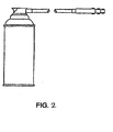
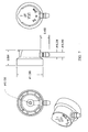
- Figs. 1-3 Illustrate an aerosol dispenser and adaptors for use with the invention
- Figs. 4-7 Illustrate various means for delivering the chemical composition of the invention to approximate areas of an engine
- Figs. 8-10 Illustrate graphs demonstrating effective use of the invention.
- Our invention provides specific compositions of matter ideal for dispersing and dissolving dense layers of heavy, baked-on carbonaceous deposits that form on surfaces within the upper internal combustion engine chambers; wherein a polar protic or dipolar aprotic solvent is synergized with a primary, secondary or tertiary amine, up to a pH valve of a least 11 (at 25 deg. C.).
- a polar protic or dipolar aprotic solvent is synergized with a primary, secondary or tertiary amine, up to a pH valve of a least 11 (at 25 deg. C.).
- a polar protic or dipolar aprotic solvent is synergized with a primary, secondary or tertiary amine, up to a pH valve of a least 11 (at 25 deg. C.).
- a polar protic or dipolar aprotic solvent is synergized with a primary, secondary or tertiary amine, up to a pH valve of
- the synergistic cleaning compositions should have a pH of 13 (at 25 deg. C.) or higher, and a dielectric constant of 35 or higher. This high level of cleaning efficiency is required because of limits imposed on engine cleaning time by OE shops, which is usually in the range of 5 to 10 minutes.
- the optimized upper engine aerosol formula for gasoline engines has a pH value of about 13.6 (25 deg. C.) and a dielectric constant of 32.01. When this optimized composition is blended in the order listed, (with moderate agitation) the batch temperature increases by approximately 16% after adding De-Ionized Water to N-Methylformamide and then increases another 16% when the primary alkylamine is added.
- the blend tank should be tightly closed and maintained with slow agitation until the batch temperature returns to room temperature.
- the blending room should be well ventilated.
- the aerosol is made by a two stage fill. First filling the concentrate into the aerosol unit and then pressure filling with the propellant and mechanically crimping the valve onto the aerosol unit. When this composition is sprayed into a test jar, using the appropriate adapter, about 40% of the product is gassed-off, due to propellant evaporation. The remaining fluid, approximately 50 ml of liquid product will typically have a temperature of about -4 deg. F. (-20 deg. C.). (50% or more of the propellant evaporates when sprayed into the plenum of a warmed-up engine, which raises the dielectric constant of the fluid to 50 plus).
- the plug To conduct the spark plug cleaning test, the plug must be lowered very slowly into the very cold liquid. This will cause some boiling, but will avoid an excessive boil-out and loss of some liquid. Use a stopwatch or other timer and wait for two (2) minutes; then lift out the plug. The test solution is then slowly poured into the standard 250 ml cylinder and brought to 250 ml with De-ionized Water, taking care not to have an excessive final boil-off of propellant. Stir until uniform. Transfer some of this solution into the Orbeco-Hellige glass tube and insert into the colorimetric test unit. Under these very cold conditions the scale reading will typically show 3.4, indicating that about 35% of the baked-on carbonaceous deposit has been dispersed and dissolved.
- the optimized formula for preventative maintenance is packaged as a 7.5 ounce (212 grams) filled in an aerosol container, which is then attached to the upper engine plenum by the use of a special adapter ( Fig. 1 ). It is important to assure that the product is delivered into the plenum in form of a mist of finely divided particles. To do this we have selected two capillary type extension tubes; one with a 0.033" (0.84 mm) and one with a 0.042" (1.07 mm) inside diameter. [See Fig. 4 , Product part No. 610000 (0.042 I.D.) and Product Part No. 640000 (0.033 I.D.)].
- capillary tubes are inserted into a Locking Actuator Cap.
- the O.D. of the capillary tube is 0.102" (02.59 mm) and the I.D. of the tube housing which protrudes from the Locking Actuator Cap is 0.107" (2.718 mm) and narrows to 0.100" (2.54 mm) at the center of the Actuator. [See Fig. 5 A ].
- the capillary tubes are pressed firmly toward the center of the Actuator and extend out ward 30" to 40", (this long adapter lets the user place the aerosol unit away from the hot vehicle engine during the cleaning process).
- a clear PVC tube is placed over the capillary tube for protection and pressed fitted over the protruding tube-housing on the Actuator and then a multi-adapter is inserted into the other end of the clear PVC tube, so this can be attach to the air intake vehicle plenum, (See Fig. 6 , clear PVC tube.) and (See Fig. 7 , multi-adapter for the vehicle plenum).
- the capillary tube will protrude approximately one inch (1") out of the multi-adapter, so that the synergistic spray mist goes directly into the plenum.
- Using the 0.033" (0.84 mm) capillary tube adapter gives a product delivery rate of about 0.50 grams per second and will last approximately seven minutes.
- the 0.042 (1.07 mm) capillary tube adapter delivers about 0.90 gram of product per second and will empty the aerosol unit in approximately four (4) minutes. The lower delivery rate works best for small gasoline and diesel engines.
- a preferred use of this product is to attach the over-cap actuator onto the aerosol valve stem and mounting cup, and then position the other end of the eductor tube, protruding through the variable diameter plenum adapter, into the upper engine plenum. Then slowly depress the actuator pad until a mechanical feature locks the valve in an "open" position. The aerosol unit will then spray until it is empty.
- the discharge rate is normally four (4) to seven (7) minutes depending on the size of the capillary I.D. selected. Since there is no operator present, in the event that the engine should stall, the aerosol will continue to spray until empty.
- This controlled spray mist will not cause any harm to the stalled engine, because this capillary adapter prevents the possibility of discharging the synergistic mixture as a heavy wet spray or liquid stream that would tend to run down the plenum wall to the closest intake runner. It would then accumulate behind a single intake valve, or if that valve was open, it would then leak down upon the top of the piston. If these things happen, when the operator attempts to start the engine, there will be the risk of hydraulically locking it, cracking the top of the piston or bending a piston rod, thus severely damaging or even destroying the engine.
- the optimized Diesel mist formula ( Table Four), Formula 526 also requires the use of this same adapter, which will deliver a finely particled mist into the center of the intake air flow, after the air filter has been removed, and when the diesel engine is at idle speed.
- a different formula (Table Four),Formula 525 can utilize this same adapter without the capillary inner tube and without a lock-down aerosol valve actuator. (This is illustrated in Fig. 2 ).
- the adapter for this assembly is designed to deliver a heavy, wet, residual spray into the plenum of a gasoline engine and adjust the engine speed to about 1500 rpm. The mechanic will then shake the aerosol dispenser, using a spray and release technique until the aerosol is empty.
- This spray technique requires the mechanic to fully actuate the aerosol dispenser for about 5 to 10 seconds, this will produce a flooding action in the upper engine which will cause the speed to decrease to about 500 rpm. The mechanic will then shut off the spray and this will allow the engine to recover its original speed of about 1500 rpm. The procedure is repeated, until the aerosol is less than about 5% full. At this point, the aerosol should be actuated until the engine stalls, after which the dispenser can be sprayed for a few more seconds until the can is empty.
- the mechanic will then let the engine “soak” for ten (10) to fifteen (15) minutes. Then he should crank the engine very slowly until it has made one complete revolution, after which regular cranking can be initiated until the engine starts.
- the engine is brought to about 3000 rpm, then snapped to about 5000 rpm briefly, to blow out any loose carbonaceous fragments.
- the vehicle should be driven for 3 to 5 miles, to fully exhaust the combustion chambers and catalytic converter.
- Formula 525 can be effectively used to "soak" cylinders, to clean entire combustion chambers, cylinder domes, piston heads and to release compression rings that have been frozen into place by hard carbonaceous depositions.
- This cleaning technique requires the use of a unique adapter 360 degree tip (illustrated in Fig. 3 ), attached to a standard plenum adapter, by replacing the multi-adapter tip with the 360 degree brass spray tip.
- Methyl Pyrrole 66% Water 34% 6.5 27+ ---- 0 53. Methyl Pyrrolidine 11.7 9.8 ---- 2 54. Methyl Pyrrolidine 66% Water 34% 11.7 33.2 ---- 75 55. Monoethanolamine 13.1 ---- ---- 10 56. Monoethanolamine 66% Water 34% 13.1 27+ ---- 80 57. Morpholine 11.0 7.3 1.75 10 58. Morpholine 66% Water 34% 11.0 31.5 1.75 70 59. Nitromethane 6.1 35.87 3.46 0 60. Nitromethane 66% Water 34% 6.1 50.5 3.46 0 61. 1-Octyl-2-Pyrrolidinone 9.7 3.82 2 62.
- Methylformamide 10% Isopropylamine 90% 13.2 24.9 ---- 75 86.
- Methylformamlde 20% Isopropylamine 80% 13.2 44.36 ---- 100 *87.
- Dimethylether 35% Formamide 22% Isopropylamine 43% 13.2 30.85 ---- 30 *88.
- Dimethylether 35% Methylformamide 22% Isopropylamine 43% 13.2 50.46 ---- 50 *Represents 50% DME loss when spraying the aeroso. Both solution temperatures were approx. 4 deg. F. after two minutes soak time.
Abstract
Description
- Not Applicable
- Not Applicable
- Not Applicable
- Over the past fifteen (15) years or so the chemistry of the injurious, baked-on carbonaceous deposits have changed somewhat, primarily due to improvements in petroleum refining and the need to comply with various federal and state regulations. Changes have also been made in the composition of gasoline and oil additives and in mechanical aspects of engines - now increasingly controlled and monitored by numerous computer chips. All are designed to provide more engine efficiency, thus increasing U.S.EPA mileage ratings, while decreasing noxious tailpipe emissions.
- Despite these many sophistications the problem of carbonaceous deposits remains, and in fact, continues unabated. At least in part, these build-ups can be related to unsaturated hydrocarbons (olefinics), which constitute a significant percentage of fuels, and which cannot be removed by any economically feasible process. If anything, the more complex and sensitive nature of modem engines has made them more susceptible to the many problems cause by these insidious carbon-based deposits. The need for their periodic removal remains a pressing issue.
- The problems arising from the accretion of these carbonaceous engine deposits can be described with more specificity. They cause a general loss of power in the internal combustion engine. Multiplicities of factors are involved. They may cause rogue combustions that are out-of-synchrony with the timing of the primary combustion sequence. Aside from the obvious "contra-combustion" event, this acts to steal fuel from the next primary combustion stage. One result is inefficient combustion, with unburned hydrocarbons then being emitted into the atmosphere through the exhaust pipe. These fuel hydrocarbons are recognized by the U.S.EPA and the various states as Volatile Organic Compounds (VOC's), which can then act indirectly to create more ozone in the air.
- As is well documented, troposphere ozone is an extremely reactive and dangerous air contaminant, condemned by the National Academy of Science and other experts, and now regulated to a limit of 0.08 part-per-million in air as an official interpretation of the Clean Air Act Amendments of 1999. At this time most states are in non-attainment, and are straining their resources to be compliant, as evident from their State Implementation Plans (SIPS), submitted periodically to the U.S.EPA. Given this background, it will be seen that the minimization of unburned fuel (VOCs) is a very important element in tropospheric ozone reduction. It will be welcomed by both regulators and environmentalists as one of the many that will ultimately lead to cleaner air.
- Carbonaceous build-ups on valve seats (valve tulips) cause loss of compression and an interference with optimum air-to-fuel ratios. Deposits in combustion chambers act to reduce the tension in compression rings. In turn, this reduces compressions, as well as engine power. Because of unbalanced piston compressions, engine vibrations will increase, causing excessive engine wear and reduced fuel mileage, plus even more emissions of unburned hydrocarbon fuel. Deposits on spark plugs also interfere with optimum fuel bum, due to the changing of their dynamic kilovoltage (KV) and millisecond pulse width. Carbonaceous deposits in the EGR valve are the cause of engine surging, rough engine syndrome and giving a check engine light. Similarly, these deposits on the oxygen sensor unit will cause a slow response to necessary air-stoichiometric or optimum proportions. Without sufficient oxygen to bum the excess of fuel, the mileage-per-gallon will decrease and the unused fuel will be emitted into the atmosphere via the tail pipe. Finally, a build up of carbonaceous deposits on the catalytic converter screen will act to reduce the rate of heat transfer, ultimately causing the screen to disintegrate. When fragments are blown into the converter, permanent damage will result. The vehicle operator will generally be oblivious to the circumstance, often driving many thousands of miles with little or no remediation of the raw exhaust fumes before the next converter check-up.
- Numerous studies have demonstrated that carbonaceous engine deposits can reduce fuel mileage by as much as 10%, and even as high as 15%, after 15,000 to 20,000 miles of driving, especially under city driving (stop-and-go) conditions. The physico-chemical action of my invention, when properly used as a preventative maintenance program - - - typically after 15,000 miles of city driving, or about 20,000 miles of rural driving - - - will act to increase fuel efficiency by an average of 15%. In today's world of high fuel prices, concerns about air quality and fears of global warming effects this improvement in fuel efficiency can be viewed as quite significant and welcome.
- Laboratory test have been developed as early as 1985 to detect, develop and then maximized the synergistic chemistry of carbonaceous sludge removal. In particular, the Cold Spark Plug Immersion Test (CSPIT) was developed to access the ability of various solvent mixtures to disperse baked-on carbonaceous engine deposits. The preferred test is fully described in
U.S. Patent No. 4,992,187 . Spark plug deposits were given a descriptive rating of A, B, C and D, in terms of their relative thickness and density. For example, soil type C represents a fairly serious deposit representative of about 10% of all spark plug deposits. Type D is the most serious, described as "a dense, dark, carbonized baked-on deposit" and this affects the majority of spark plugs. It is very similar to the deposits found on upper internal combustion engine surfaces. - In the interest of convenience the detail of the current test procedure are presented here as follows:
- a. Approximately 100 used spark plugs must be obtained from a suitable engine tune-up shop or similar source.
- b. These spark plugs are hand-sorted to separate out those that qualify as category D.
- c. The category D spark plugs are briefly rinsed with a brake cleaner solution composed of one or more chlorinated solvents, such as trichloroethylene, after which they are dried for 24 hours at about 70 deg. F. (21 deg. C.).
- d. The evaluation is made by partially immersing individual spark plugs in typical four fluid ounce (120 ml) jars containing 1.7 fluid ounces (50 ml) of test solution. After tightening the jar lid, the jar must be briefly tilt about 45 degrees, to allow the test solution to completely fill the hollow base that contains the spark plug electrode. The jar is then stored upright for exactly five minutes at about 70 deg. F. (21 deg. C.).
- e. The jar is then opened and the spark plug removed - - - shaking it slightly to assure that the test liquid inside the spark plug fully drains back into the jar.
- f. The 1.7 fluid ounces (50 ml) of test solution is then diluted with de-ionized water to 250 ml.
- g. A suitably small aliquot of this mixture is then transferred into a colorimetric tube and placed in an Orbeco-Hellige tester, so that the color can be compared to a standard No. 620-C-43 Low Varnish Hellige Color Disc. The disc is selected to provide a range of 1 through 9 color scale, referencing ASTM D-1544. A second disc may be used, identified as standard No. 620-C-44 for High Varnish Colors. This provides an extended range: from 9 through 18.
- h. Experience has shown that a reading of ten (10) signifies 100% removal of the baked-on carbonaceous deposit. A reading of nine (9) is equivalent to a 90% removal, and so forth.
- This experimental technique has been shown to be highly reliable as a valid screening process for evaluation and ability of various test solutions to disperse and dissolve carbonaceous deposits from upper cylinder engine surfaces.
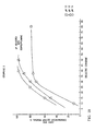
- Our invention can be employed to provide a series of synergistic liquid mixtures, each capable of dispersing and dissolving modem baked-on carbonaceous deposits from the surface of the upper cylinder area of internal combustion engines, including the spark plugs and all the other component surfaces in this enclosure. Maintaining surface cleanliness is a major element in sustaining maximum operating efficiency of these engines. We have found that polar protic and dipolar aprotic solvents, either independently or in blends having a dielectric constant above 25 or more, can be synergized by raising the pH value to 11 or above (at 25 deg. C.). (See
Fig. 10 , Graph No. 3). - As the dielectric constant increases beyond 30, cleaning efficacy also increases. Methyl Formamide, with a uniquely high dielectric constant in excess of 200, is unusually effective. We have, in fact, found two single compounds able to clean modem upper cylinder carbonaceous deposits without the usual need to be synergized. These are Hydrazine (and certain close derivatives), with a dielectric constant of about 53 and a pH valve of over 13 (at 25 deg. C.), as well as concentrated aqueous Ammonium Hydroxide Solutions (typically with 28.6% ammonia content), and having a dielectric constant of about 61 and a pH valve of over 13 (25 deg. C.).
- Our invention provides three distinct techniques for cleaning the component of the upper cylinder area of internal combustion engines. These are:
- 1. A preventative technique, wherein the synergistic product is delivered as a finely particulated spray into the plenum of the upper engine while the engine is at idling speed. The product is ideally delivered from a self-pressurized (aerosol) dispenser.
Once attached to the plenum by means of a hose and adapter, the aerosol actuator is fully depressed and locked down. The system is then fully independent of manual control and can be left alone until the injection operation is complete. The length of chemical contact time is approximately five (4) to six (7) minutes, depending on the LD. of the capillary dispensing tube, which produces optimum delivery rate - - - and is thus the same as in the laboratory simulation test. - 2. A "hands-on" engine maintenance technique, where the synergistic composition is delivered into the engine plenum in the form of a heavy, oscillating type residual spray, while the engine is running at about 1500 rpm. This mode requires constant control by an operator.
- 3. This technique involves a maintenance process requiring that a trained mechanic remove the spark plugs from a fully warmed-up engine, and then, using a special adapter, simply attach to the self-pressurized (aerosol) and then enter the tip of the adapter into the threaded spark plug hole. The synergistic formulation is then sprayed into each upper cylinder area for five (5) seconds, after which the spark plugs are replaced with one thread turn or very loose and then the engine is permitted to hot soak for approximately one hour. All of the spark plugs are then removed and a towel, wet with water, is placed over the spark plug holes. Then spend the engine, thus through-in out, the liquid carbonaceous deposits which are absorbed into the wet towels safely.
- In the marketing of products that take advantage of this invention, aerosols with the desired synergistic composition and pre-determined delivery rate would be made available, together with the appropriate connector of plastic tubing and adapters. Each aerosol dispenser could be sized to provide maintenance for a multiplicity of internal combustion engines.
- In the drawings:
1. Figs. 1-3 :Illustrate an aerosol dispenser and adaptors for use with the invention, 2. Figs. 4-7 :Illustrate various means for delivering the chemical composition of the invention to approximate areas of an engine, and 3. Figs. 8-10 :Illustrate graphs demonstrating effective use of the invention. - Our invention provides specific compositions of matter ideal for dispersing and dissolving dense layers of heavy, baked-on carbonaceous deposits that form on surfaces within the upper internal combustion engine chambers; wherein a polar protic or dipolar aprotic solvent is synergized with a primary, secondary or tertiary amine, up to a pH valve of a least 11 (at 25 deg. C.). As notation alkali metal hydroxides cannot be used as synergists because of their ability to chemically attack aluminum engine components, etching the metal and producing solid aluminate salts that are potentially more damaging to the engine than the carbonaceous deposits.
- We have found that high dielectric constant formulations with pH valves ten (10) or less display little or no ability to disperse and dissolve carbonaceous deposits. (See Table One for details.) Additionally, formulas with a
satisfactory pH value 11 to 13 plus, but with a dielectric constant below about 15, also shows very limited ability to disperse and dissolve these deposits. (See Table Two for details.) However, compositions with suitably high PH values (above 11) and dielectric constants (above 25) display very satisfactory removals of carbonaceous deposits, typically 80 to 100%. (See Table Three for details.) - Test results from actual cleaning of upper engine areas show that, ideally, the synergistic cleaning compositions should have a pH of 13 (at 25 deg. C.) or higher, and a dielectric constant of 35 or higher. This high level of cleaning efficiency is required because of limits imposed on engine cleaning time by OE shops, which is usually in the range of 5 to 10 minutes. (See Table Four.) The optimized upper engine aerosol formula for gasoline engines has a pH value of about 13.6 (25 deg. C.) and a dielectric constant of 32.01. When this optimized composition is blended in the order listed, (with moderate agitation) the batch temperature increases by approximately 16% after adding De-Ionized Water to N-Methylformamide and then increases another 16% when the primary alkylamine is added. Accordingly the blend tank should be tightly closed and maintained with slow agitation until the batch temperature returns to room temperature. The blending room should be well ventilated. The aerosol is made by a two stage fill. First filling the concentrate into the aerosol unit and then pressure filling with the propellant and mechanically crimping the valve onto the aerosol unit. When this composition is sprayed into a test jar, using the appropriate adapter, about 40% of the product is gassed-off, due to propellant evaporation. The remaining fluid, approximately 50 ml of liquid product will typically have a temperature of about -4 deg. F. (-20 deg. C.). (50% or more of the propellant evaporates when sprayed into the plenum of a warmed-up engine, which raises the dielectric constant of the fluid to 50 plus).
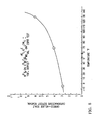
- To conduct the spark plug cleaning test, the plug must be lowered very slowly into the very cold liquid. This will cause some boiling, but will avoid an excessive boil-out and loss of some liquid. Use a stopwatch or other timer and wait for two (2) minutes; then lift out the plug. The test solution is then slowly poured into the standard 250 ml cylinder and brought to 250 ml with De-ionized Water, taking care not to have an excessive final boil-off of propellant. Stir until uniform. Transfer some of this solution into the Orbeco-Hellige glass tube and insert into the colorimetric test unit. Under these very cold conditions the scale reading will typically show 3.4, indicating that about 35% of the baked-on carbonaceous deposit has been dispersed and dissolved. If the same experiment is performed, but now at 70 deg. F. (21 deg. C.) the scale reading will be about 5.0. At 100 deg. F. (38 deg. C.) the reading is about 6.2, and at 130 deg. F. (54 deg. C.) it is 8.5. (These data are displayed on
Fig. 8 , Graph Number One.) The solubility activity continues to increase at still higher contact temperatures. (SeeFig. 9 , Graph Number Two). Diluting the test sample in De-ionized Water and then transferring an aliquot sample of the dilution for reading should be conducted as quickly as possible for accurate readings. When the diluted test solution sets for five (5) to ten (10) minutes a gelatinous precipitation occurs which interferes with an accurate reading. - On a fully warmed engine the lower area of the plenum temperature will average about 150 deg. F. (62 deg. C.), and this increases to about 220 deg. F. (105 deg. C.) on the surfaces of the intake valves. Engine test have shown that the optimum time for the synergistic composition to contact the carbonaceous deposits in these areas to be between four (4) to six (6) minutes.
- The optimized formula for preventative maintenance, as illustrated in Table Four (Formula 524), is packaged as a 7.5 ounce (212 grams) filled in an aerosol container, which is then attached to the upper engine plenum by the use of a special adapter (
Fig. 1 ). It is important to assure that the product is delivered into the plenum in form of a mist of finely divided particles. To do this we have selected two capillary type extension tubes; one with a 0.033" (0.84 mm) and one with a 0.042" (1.07 mm) inside diameter. [SeeFig. 4 , Product part No. 610000 (0.042 I.D.) and Product Part No. 640000 (0.033 I.D.)]. These capillary tubes are inserted into a Locking Actuator Cap. The O.D. of the capillary tube is 0.102" (02.59 mm) and the I.D. of the tube housing which protrudes from the Locking Actuator Cap is 0.107" (2.718 mm) and narrows to 0.100" (2.54 mm) at the center of the Actuator. [SeeFig. 5 A ]. The capillary tubes are pressed firmly toward the center of the Actuator and extend outward 30" to 40", (this long adapter lets the user place the aerosol unit away from the hot vehicle engine during the cleaning process). A clear PVC tube is placed over the capillary tube for protection and pressed fitted over the protruding tube-housing on the Actuator and then a multi-adapter is inserted into the other end of the clear PVC tube, so this can be attach to the air intake vehicle plenum, (SeeFig. 6 , clear PVC tube.) and (SeeFig. 7 , multi-adapter for the vehicle plenum). The capillary tube will protrude approximately one inch (1") out of the multi-adapter, so that the synergistic spray mist goes directly into the plenum. Using the 0.033" (0.84 mm) capillary tube adapter gives a product delivery rate of about 0.50 grams per second and will last approximately seven minutes. The 0.042 (1.07 mm) capillary tube adapter delivers about 0.90 gram of product per second and will empty the aerosol unit in approximately four (4) minutes. The lower delivery rate works best for small gasoline and diesel engines. - A preferred use of this product is to attach the over-cap actuator onto the aerosol valve stem and mounting cup, and then position the other end of the eductor tube, protruding through the variable diameter plenum adapter, into the upper engine plenum. Then slowly depress the actuator pad until a mechanical feature locks the valve in an "open" position. The aerosol unit will then spray until it is empty. The discharge rate is normally four (4) to seven (7) minutes depending on the size of the capillary I.D. selected. Since there is no operator present, in the event that the engine should stall, the aerosol will continue to spray until empty. This controlled spray mist will not cause any harm to the stalled engine, because this capillary adapter prevents the possibility of discharging the synergistic mixture as a heavy wet spray or liquid stream that would tend to run down the plenum wall to the closest intake runner. It would then accumulate behind a single intake valve, or if that valve was open, it would then leak down upon the top of the piston. If these things happen, when the operator attempts to start the engine, there will be the risk of hydraulically locking it, cracking the top of the piston or bending a piston rod, thus severely damaging or even destroying the engine.
- The optimized Diesel mist formula ( Table Four), Formula 526, also requires the use of this same adapter, which will deliver a finely particled mist into the center of the intake air flow, after the air filter has been removed, and when the diesel engine is at idle speed. Alternatively, a different formula (Table Four),Formula 525, can utilize this same adapter without the capillary inner tube and without a lock-down aerosol valve actuator. (This is illustrated in
Fig. 2 ). The adapter for this assembly is designed to deliver a heavy, wet, residual spray into the plenum of a gasoline engine and adjust the engine speed to about 1500 rpm. The mechanic will then shake the aerosol dispenser, using a spray and release technique until the aerosol is empty. This spray technique requires the mechanic to fully actuate the aerosol dispenser for about 5 to 10 seconds, this will produce a flooding action in the upper engine which will cause the speed to decrease to about 500 rpm. The mechanic will then shut off the spray and this will allow the engine to recover its original speed of about 1500 rpm. The procedure is repeated, until the aerosol is less than about 5% full. At this point, the aerosol should be actuated until the engine stalls, after which the dispenser can be sprayed for a few more seconds until the can is empty. - The mechanic will then let the engine "soak" for ten (10) to fifteen (15) minutes. Then he should crank the engine very slowly until it has made one complete revolution, after which regular cranking can be initiated until the engine starts. The engine is brought to about 3000 rpm, then snapped to about 5000 rpm briefly, to blow out any loose carbonaceous fragments. Finally, the vehicle should be driven for 3 to 5 miles, to fully exhaust the combustion chambers and catalytic converter.
- Over 300 tests have been conducted, to fully refine and demonstrate the superior upper engine cleaning activity, resulting from the use of this high dielectric constant formulation, when synergized by the inclusion of high pH valve ingredients, and when applied to older vehicles and some relative new vehicles, Formula 525 can be effectively used to "soak" cylinders, to clean entire combustion chambers, cylinder domes, piston heads and to release compression rings that have been frozen into place by hard carbonaceous depositions. This cleaning technique requires the use of a unique adapter 360 degree tip (illustrated in
Fig. 3 ), attached to a standard plenum adapter, by replacing the multi-adapter tip with the 360 degree brass spray tip. - See Table No.5 for a more complete summary of data listed in Tables No.'s 1,2 and 3. There does not appear to be a direct correlation between the chemicals dipole moment and synergism.
TABLE No.1 CHEMICALS TESTED pH DIELECTRIC CONSTANT ORBECO-HELLlGE TEST % REMOVAL CSPIT RESULTS ACETONE 7.5 20.7 2 ACETONITRILE 6.5 37.5 0 ETHYL ALCOHOL 7.5 24.3 0 ETHYLENE GLYCOL 7.0 41.2 0 N-ETHYL-2-PYRROLIDONE 10.0 29.0 20 FORMAMIDE 9.0 111.0 10 GLYCERIN 8.0 42.5 0 HEXAMETHYLPHOSPHORAMIDE 7.7 30.0 0 ISOPROPYL ALCOHOL 7.5 18.3 0 N-HYDROXYETHYL-2-PYRROLIDONE 9.8 ---- 0 METHYL ALCOHOL 7.5 41.8 1 METHYLFORMAMIDE 7.5 200.1 10 METHYL PYRROLE 6.5 ---- 0 NUROMETHANE 6.1 35.9 0 1-OCTYL-2-PYRROLIDIONE 9.7 ---- 2 2-PYRROLIDONE 10.5 12.5 10 TETRAMETHYLENE SULFONE 8.0 ---- 0 TABLE No. 2 CHEMICALS TESTED pH DIELECTRIC CONSTANT ORBECO-HELLIGE TEST % REMOVAL CSPIT RESULTS ALLYLAMINE 12.3 3.2 15 BUTYLAMINE 12.5 4.88 5 BUTYL PYRROLIDINE 11.2 ---- 0 CYCLOHEXYLAMINE 12.5 4.73 0 DIETHYLAMINE 13.3 3.7 2 ISOBUTYLAMINE 12.3 4.43 5 ISPPROPYLAMINE 13.3 5.45 10 METHYL PYRROLIDM 11.7 9.8 2 MONOETHANOLAMINE 13.1 ---- 10 MORPHOLINE 11.0 7.3 10 TETRAHYDROFURFURYLAMINE 12.5 ---- 10 TRIETEIYLAMINE 12.0 2.42 0 TABLE No. 3 CHEMICALS TESTED pH DIELECTRIC CONSTANT ORBECO-HELLIGE TEST % REMOVAL CSPIT RESULTS Methylformamide 98.8% Isopropylamine 1.2% 12.0 197.8 100 Formamide 98.4% Isopropylamine 1.6% 12.0 109.4 90 Deionized water 98.0% Isopropylamine 2.0% 12.0 78.5 90 Dimethyl Sulfoxide 98.8% Isopropylamine 1.2% 12.0 48.4 90 Methanol 90.0% Isopropylamine 10.0% 12.0 38.2 100 Ethylene Glycol 90.0% Isopropylamine 10.0% 12.0 37.6 80 Formamide 83.0% Isopropylamine 17.0% 12.8 93 100 Formamide 20.0% Isopropylamine 80.0% 13.3 26.6 90 Pyrrolidine 66.0% Deionized water 34.0% 13.2 ∼ 30.0 80 Tert Butylamine 66.0% Deionized water 34.0% 11.8 29.4 80 Triethylamine 64.0% Deionized water 36.0% 12.0 30.3 80 Methyl Alcohol 30.0% Isopropylamine 70.0% 13.3 16.4 60 Ethylene Glycol 50.0% Isopropylamine 50.0% 13.3 23.3 70 Methylformamide 10.0% Isopropylamine 90.0% 13.2 24.9 80 Methylformamide 20.0% Isopropylamine 80.0% 13.2 44.4 100 Methylformamide 6.0% Isopropylamine 94.0% 13.3 17.1 60-70 Methylformamide 60.0% Pyrrolidine 40.0% 13.5 120.0 90 Methylformamide 60.0% 2-Furfurylamine 40.0% 12.0 120.0 60 Butyl Pyrrolidine 66.0% Deionized water 34.0% 11.2 ∼ 30.0 70 2-Furfurylamine 66.0% Deionized water 34.0% 11.5 27 + 70 + Morpholine 66.0% Deionized water 34.0% 11.0 31.5 70 Monoethanolamine 66.0% Deionized Water 34.0% 13.1 27 + 80 Isobutylamine 66.0% Deionized water 34.0% 12.3 29.6 80 Methylformamide 99.4% Sodium Hydroxide 50% 0.6% 12.0 199 100 Methylformamide 95.6% Ammonia Hydroxide 28% 4.4% 12.0 194 100 Methylformamide 97.4% Hydrazine 2.6% 12.0 196.3 100 TABLE No. 4 PREFERRED FORMULA No. 522
INTERNAL COMBUSTION ENGINE SOAKING FOR 30 MINUTES TO ONE HR.pH DIELECTRIC CONSTANT CSPIT TEST Methylformamide 25.00% sparkplug placed in test jar with 50 ml's of formula: two minute soak time, score = 8 Deionized Water 54.60% Isopropylamine 20.00% Air 0.40% 13.6 94.79 PREFERRED FORMULA No. 524
MIST SPRAY FOR GASOLINE ENGINESMethylformamide 10.00% Sparkplug placed in test jar, spray in 50 ml's of formula, temp. was -4 deg. F. with 40% loss of DME. Soak time two minutes; Score = 3.5. In five minutes; Score = 10.0 with 60% DME boiled off. Deionized Water 10.00% Isopropylamine 10.00% Dimethyl Ether 70.00% 13.6 32.01 After 40% DME loss 13.6 50.06 After 60% DME loss 13.6 72.61 PREFERRED FORMULA No. 526
MIST SPARY FOR DIESEL ENGINESMethylformamide 11.35% Sparkplug placed in test jar, spray in 50 ml's of formula, temp. was -8 deg.F. With 40% loss of A-70. Soak time Five minutes; score = 2. Ten minute Score = 4. (Twenty Minute score = 8. Temp. 30 deg. F.). Isopropyl Alcohol 11.65% Isopropylamine 10.00% A-70 Propellant 67.00% 13.3 27.08 PREFERRED FORMULA No. 525
RESIDUAL SPRAY FOR GASOLINE ENGINESMethylformamide 25.00% Sparkplug placed in test jar, spray in 50 ml's of formula. temp. approx. 70 Deg. F. soak time Two minutes; score = 5. soak time four Minutes; score = 8. Deionized Water 46.21% Isopropylamine 15.00% A-46 Propellant 13.79% 13.3 88.03 PREFERRED ALTERNATE FORMULA No. 527
MIST SPRAY FOR GASOLINE ENGINESMethylformamide 11.35% Isopropyl Alcohol 11.65% Isopropylamine 10.00% P-152a Propellent 67.00% 13.3 27.0 Test results are Or (P-161 Propellant) Similar to formula Or (other Hydrofluorocarbon Propellants) No. 526. TABLE No. 5 CSPIT TEST ON POLAR PROTIC AND DIPLOAR APROTIC SOLVENTS: CHEMICALS TESTED pH D.E.C. D.P.M. CSPIT TEST RESULTS 1. Acetamide 6.0 60.6 3.9 2 2. Acetone 7.8 20.7 2.77 5 3. Acetone 66% Water 34% 7.8 37.0 2.77 7 4. Acetonitrile 6.5 37.5 3.97 0 5. Acetonitrile 66% Water 34% 6.5 51.66 3.97 0 6. Allylamine 12.3 3.2 1.3 15 7. Allylamine 66% Water 34% 12.2 28.0 1.3 80 8. Ammonium Hydroxide 28 Be. 12.4 61.0 ---- 80 9. 1-Amino-2-Propanol 13.7 ---- ---- 20 10. 1-Amino-2-Propanol 66% Water 34% 13.6 27.2+ ---- 50 11. 3-Amino-1-Propanol 13.7 ---- ---- 10 12. 3-Amino-1-Propanol 66% Water 34% 13.6 27.2+ ---- 50 13. Butylamine 12.5 4.88 1.0 5 14. Butylamine 66% Water 34% 12.5 30.0 1.0 80 15. Butyl Pyrrolidine 11.2 ---- ---- 0 16. Butyl Pyrrolidine 66% Water 34% 11.2 ∼30.0 ---- 70 17. Cycohexylamine 12.5 4.73 3.8 0 18. Cyclohexylamine 66% Water 34% 11.8 30.0 ---- 75 19. Diethylamine 13.3 3.7 ---- 2 20. Diethylamine 66% Water 34% 13.3 29.1 ---- 75 21. Dimethylacetamide 11.0 37.78 3.8 70 22. Dimethylacetamide 66% Water 34% 8.0 51.8 3.8 20 23. Dimethylformamide 10.5 38.3 3.66 20 24. Dimethylformamide 66% Water 34% 7.6 52.2 3.66 5 25. Dimethylsulfoxide 10.5 48.9 3.9 25 26. Dimethylsulfoxide 66% Water 34% 8.5-9.0 59.3 3.9 10 27. Ethylene Glycol 7.0 41.2 2.27 0 28. Ethylene Glycol 66% Water 34% 7.0 54.1 2.27 0 29. N-Ethyl-2-pyrrolidone 10.0 29.0 ---- 20 30. N-Ethyl-2-pyrrolidone 66% Water 34% 10.0 46.0 ---- 20 31. Formamide 9.0 111.0 3.73 10 32. Formamide 66% Water 34% 8.5 100.6 3.73 10 33. Glycerin 8.0 42.5 2.68 0 34. Glycerin 66% Water 34% 8.0 55.0 2.68 0 35. Hexamethylphosphoramide 7.7 30.0 4.31 0 36. Hexamethylphosphoramide 66% Water 34% 7.7 46.6 4.31 2 37. Hydrazine 13.0 52.9 ---- 100 38. Hydrazine 64% / Water 36% 13.0 62.0 ---- 80 39. N-Hydroxyethyl-2-Pyrrolidone 9.8 ---- ---- 0 40. N-Hydroxyethyl-2-Pyrrolidone 66% Water 34% 9.3 27+ ---- 0 41. Isobutylamine 12.3 4.43 1.27 5 42. Isobutylamine 66% Water 34% 12.3 29.6 1.27 80 43. Isopropylamine 13.3 5.45 1.45 3 44. Isopropylamine 66% Water 34% 13.3 30.3 1.45 80 45. Isopropylamine 90 % Water 10% 13.3 12.9 1.45 15 46. Isopropylamine 94 % Water 6% 13.3 9.92 1.45 10 47. Methyl Alcohol 7.5 41.8 1.69 1 48. Methyl Alcohol 66% Water 34% 7.5 54.5 1.69 1 49. Methylformamide 7.5 200.1 3.86 20 50. Methylformamide 66% Water 34% 7.5 160.0 3.86 5 51. Methyl Pyrrole 6.5 ---- ---- 0 52. Methyl Pyrrole 66% Water 34% 6.5 27+ ---- 0 53. Methyl Pyrrolidine 11.7 9.8 ---- 2 54. Methyl Pyrrolidine 66% Water 34% 11.7 33.2 ---- 75 55. Monoethanolamine 13.1 ---- ---- 10 56. Monoethanolamine 66% Water 34% 13.1 27+ ---- 80 57. Morpholine 11.0 7.3 1.75 10 58. Morpholine 66% Water 34% 11.0 31.5 1.75 70 59. Nitromethane 6.1 35.87 3.46 0 60. Nitromethane 66% Water 34% 6.1 50.5 3.46 0 61. 1-Octyl-2-Pyrrolidinone 9.7 3.82 2 62. 1-Octyl-2-Pyrrolidinone 66% Water 34% 9.7 3.82 10 63. 2-Pyrrolidone 10.5 12.5 3.55 10 64. 2-Pyrrolidone 66% Water 34% 10.5 35 3.55 25 65. Tert Butylamine 11.5 4.2 1.29 2 66. Tert Butylamine 66% Water 34% 11.5 29.4 1.29 80 67. Tetrahydrofurfurylamine 12.5 ---- ---- 10 68. Tetrahydrofurfurylamine 66% Water 34% 12.5 27+ ---- 70 69. Tetramethylene Sulfone 8.0 ---- ---- 0 70. Tetramethylene Sulfone 66% Water 34% 8.0 27+ ---- 15 71. Triethylamine 12.0 2.42 .66 0 72. Triethylamine 66% Water 34% 12.0 28.3 .66 80 73. Sodium Methylate 25%(in methanol) 12.1 31.4 2 74. Sodium Methylate 25%66% Water 34% 12.1 47.6 ---- 2 75. Sodium Methoxide 10% in Water 123 ∼72 ---- 10 76. Acetonitrile 50 % Isopropylamine 50% 13.7 24.8 ---- 80 77. Formamide 20 % Isopropylamine 80% 13.3 23.3 ---- 95 78. Acetone 66% Isopropylamine 34% 12.5 15.6 ---- 15 79. Methanol 66% Isopropylamine 34% 12.5 29.4 ---- 80 80. Methanol 30 % Isopropylamine 70% 13.3 16.4 ---- 40 81. Ethylene Glycol 50 % Isopropylamine 50% 13.3 23.3 ---- 80 82. Methyl Formamide 6% Isopropylamine 94% 13.3 17.13 ---- 50 83. Dimethylsulfoxide 34% Isopropylamine 66% 14 20.22 ---- 80 84. Furfural 50 % Isopropylamine 50% 13.0 23.7 ---- 75 85. Methylformamide 10 % Isopropylamine 90% 13.2 24.9 ---- 75 86. Methylformamlde 20 % Isopropylamine 80% 13.2 44.36 ---- 100 *87. Dimethylether 35% Formamide 22% Isopropylamine 43% 13.2 30.85 ---- 30 *88. Dimethylether 35% Methylformamide 22% Isopropylamine 43% 13.2 50.46 ---- 50 * Represents 50% DME loss when spraying the aeroso. Both solution temperatures were approx. 4 deg. F. after two minutes soak time.
Claims (21)
- An upper internal combustion engine cleaner composition comprising:(a) one or more polar protic or dipolar aprotic solvents each having a melting point above 32°F. (O°C.),(b) wherein said solvents are selected from the following group that have dielectric constants ranging from 200 to about 15 as indicated after the solvent name:
N-Methylformamide 200.1 Formamide 111.0 Water 80.0 Ammonium Hydroxide 26.8% 61.0 Nitrosodimethylamine 54.0 Hydrazine 52.9 Dimethyl Sulfoxide 48.9 Glycerin 42.5 Methanol 41.9 Ethylene Glycol 41.2 Dimethyl Formamide 38.3 Dimethyl Acetamide 37.8 Acetonitrile 37.5 Nitromethane 35.9 Hexamethyl Phosphoramide 30.0 N-Ethyl-2-Pyrrolidone 29.0 Ethanol 24.3 Allyl Alcohol 22.8 Acetone 20.7 Isopropanol 18.3
(c) wherein said composition contains a synergistic amount to bring the pH value to 11 (at 25°C.) or higher, of a compound which is an organic alkaline nitrogen- containing compound. - The upper engine cleaning composition of claim 1 wherein the alkaline nitrogen- containing compound is select from the group of primary, secondary or tertiary alkylamines, hydrazine, ammonium hydroxide solutions, quaternary ammonium hydroxides, and their derivatives.
- The upper engine cleaning composition of claim 1 wherein the alkaline nitrogen- containing compound is a primary, secondary or tertiary amine.
- The upper engine cleaning composition of claim 1 wherein the alkaline nitrogen- containing compound is a primary amine.
- The upper engine cleaning composition of claim 1 wherein the alkaline nitrogen- containing compound is a secondary amine.
- The upper engine cleaning composition of claim 1 wherein the alkaline nitrogen- containing compound is a tertiary amine.
- The upper engine cleaning composition of claim 1 wherein the solvent having the dielectric is an alkylamide.
- The upper engine cleaning composition of claim 7 wherein the alkylamide is methylformamide.
- The upper engine cleaning composition of claim 1 wherein the solvent having the dielectric constant is hydrazine.
- The upper engine cleaning composition of claim 1 wherein the solvent having the dielectric constant is an ammonium hydroxide solution.
- The upper engine cleaning composition of claim 1 wherein the solvent having the dielectric constant is a quaternary ammonium hydroxide.
- The upper engine cleaning composition of claim 1 wherein the synergistic solvent composition is blended with dimethyl ether (DME) and wherein the final blend has a dielectric constant above 15, with a pH value above 11, and is packaged in a self-pressurized aerosol dispenser.
- The upper engine cleaning composition of claim 12 which is delivered to a motor vehicle plenum via a protected capillary tube and an adapter, providing a finely particulated, misty spray, suitable for cleaning baked-on carbonaceous deposits from an upper engine surface while said engine is idling, and without the presence of an operator.
- The upper engine cleaning composition according to claim 1, wherein the composition is blended with hydrocarbon propellants selected from propane, isobutene, n-butane and mixtures thereof, and where the final blend has a dielectric constant above 15 and a pH value at 25°C. Above 11, and which is packaged in a self-pressurized aerosol dispenser.
- The upper engine cleaning composition of claim 14 which is delivered to a motor vehicle plenum via a protected capillary tube and an adapter, providing a finely particulated, misty spray, suitable for cleaning baked-on carbonaceous deposits from an upper engine surface while said engine is idling, and without the presence of an operator.
- The upper engine cleaning composition according to claim 1, wherein the composition is blended with 1,1-difluoroethane (HFC-152a), fluoroethane (HFC-161), or other hydro fluorocarbon propellants and where the final blend has a dielectric constant above 15 and a pH value at 25°C, greater than 11, and which is packaged in a self-pressurized aerosol dispenser.
- The upper engine cleaning composition of claim 16 which is delivered to a motor vehicle plenum via a protected capillary tube and an adapter, with valve orifice and inside capillary diameter designed to provide a finely particulated, misty spray, suitable for cleaning baked-on carbonaceous deposits from an upper engine surface while said engine is idling, and without the presence of an operator.
- The upper engine cleaning composition of claim 1, wherein the synergistically activated solvent has a dielectric constant of at least 35 and a pH value of at least 12, at 25°C, and is packaged in a self-pressurized aerosol dispenser.
- An upper engine cleaning composition of claim 18 which is pressurized with a small amount of propane, isobutene, n-butane hydrocarbon propellent or their mixtures, in order to deliver a large particulated, heavy wet spray into a vehicle's plenum by use of a vapor tap valve and with the use of a standard, adapter, without the use of a capillary tube, in the presence of an operator.
- The upper engine cleaning composition of claim 18 that is contained in a self-pressurized aerosol dispenser and pressurized with about 29 to 181 psi-g at 70°F (2.0 to 12.1°C) of nitrous oxide, compressed air, nitrogen, argon, hydrocarbon or fluorocarbon propellant in order to deliver a heavy, wet, spray where the mean aerodynamic particle size diameter is greater than about 0.002 (50 microns), into the combustion chambers of a fully warmed engine for about 30 to 50 minutes soak time, using a 360 degree spray adapter in the presence of an operator.
- A process for removing carbonaceous deposits on the upper cylinder areas of internal combustion engines which comprises contacting said upper cylinder areas with the upper engine cleaning composition of claim 1.
Applications Claiming Priority (1)
| Application Number | Priority Date | Filing Date | Title |
|---|---|---|---|
| MX2008007886A MX2008007886A (en) | 2007-07-03 | 2008-06-18 | Upper engine cleaning adaptors used to connect a pressurized unit containing an upper engine cleaner to the vehicles plenum. |
Publications (1)
| Publication Number | Publication Date |
|---|---|
| EP2138557A1 true EP2138557A1 (en) | 2009-12-30 |
Family
ID=40029084
Family Applications (1)
| Application Number | Title | Priority Date | Filing Date |
|---|---|---|---|
| EP08015093A Withdrawn EP2138557A1 (en) | 2008-06-18 | 2008-08-27 | An upper internal combustion engine cleaning composition |
Country Status (1)
| Country | Link |
|---|---|
| EP (1) | EP2138557A1 (en) |
Cited By (2)
| Publication number | Priority date | Publication date | Assignee | Title |
|---|---|---|---|---|
| WO2012025227A1 (en) * | 2010-08-24 | 2012-03-01 | Tunap Industrie Chemie Gmbh & Co. Produktions Kg | Method and device for cleaning coked cavities, in particular inlet channels and valves of an internal combustion engine |
| CN104736808A (en) * | 2012-07-27 | 2015-06-24 | 塞尔瓦斯实验室有限公司 | Catalytic converter, a kit for servicing a catalytic converter, and method for servicing a catalytic converter |
Citations (18)
| Publication number | Priority date | Publication date | Assignee | Title |
|---|---|---|---|---|
| US1176425A (en) * | 1914-09-08 | 1916-03-21 | Bristol Company | Hygrometer. |
| GB116010A (en) * | 1917-09-27 | 1918-05-30 | John Broadbent Perkins | A New or Improved Solution for Decarbonising and Cleansing the Interiors of Internal-combustion Engines. |
| US1787789A (en) * | 1931-01-06 | A corpora | ||
| US2047191A (en) * | 1932-05-03 | 1936-07-14 | Standard Oil Dev Co | Carbon remover and method of using the same |
| US2700005A (en) * | 1951-10-19 | 1955-01-18 | Standard Oil Co | Removal of combustion chamber deposits by solvent spraying |
| US4992187A (en) | 1989-11-15 | 1991-02-12 | Petro Chemical Products, Inc. | Composition for cleaning an internal combustion engine |
| JPH04154900A (en) * | 1990-10-19 | 1992-05-27 | Asahi Chem Ind Co Ltd | Cleaning of acrylonitrile-aromatic vinyl-based polymer material |
| EP0580413A1 (en) * | 1992-07-20 | 1994-01-26 | Exxon Research And Engineering Company | Method for carbonaceous deposit removal and for reducing engine octane requirement |
| WO1995028236A1 (en) * | 1994-04-14 | 1995-10-26 | Engine Fog, Inc. | Engine cleaner composition, method, and apparatus |
| US5693599A (en) * | 1993-12-16 | 1997-12-02 | Mitsubishi Gas Chemical Company, Inc. | Flux washing agent |
| WO2002046588A1 (en) * | 2000-12-07 | 2002-06-13 | 3M Innovative Properties Company | Method of cleaning an internal combustion engine using an engine cleaner composition and fluid-dispensing device for use in said method |
| US20020116782A1 (en) * | 1997-05-23 | 2002-08-29 | Bowsman Shelba F. | Engine decarbonizing system |
| US20030060382A1 (en) * | 2001-09-21 | 2003-03-27 | Hynix Semiconductor Inc. | Solution composition for removing a remaining photoresist resin |
| WO2004113461A1 (en) * | 2003-06-20 | 2004-12-29 | Ppg Industries Ohio, Inc. | Concentrate composition and process for removing coatings from surfaces such as paint application equipment |
| EP1610185A2 (en) * | 2004-06-15 | 2005-12-28 | Air Products And Chemicals, Inc. | Composition and method using same for removing residue from a substrate |
| WO2006011747A1 (en) * | 2004-07-28 | 2006-02-02 | Samyangems Co., Ltd. | Aqueous resist stripper composition |
| WO2007104746A1 (en) * | 2006-03-13 | 2007-09-20 | Basf Aktiengesellschaft | Cleaning composition for removing post-dry-etch residues |
| US20090011968A1 (en) * | 2007-07-03 | 2009-01-08 | Paul Hughett | Upper engine cleaning adaptors used to connect a pressurized unit containing an upper engine cleaner to the vehicles plenum |
-
2008
- 2008-08-27 EP EP08015093A patent/EP2138557A1/en not_active Withdrawn
Patent Citations (18)
| Publication number | Priority date | Publication date | Assignee | Title |
|---|---|---|---|---|
| US1787789A (en) * | 1931-01-06 | A corpora | ||
| US1176425A (en) * | 1914-09-08 | 1916-03-21 | Bristol Company | Hygrometer. |
| GB116010A (en) * | 1917-09-27 | 1918-05-30 | John Broadbent Perkins | A New or Improved Solution for Decarbonising and Cleansing the Interiors of Internal-combustion Engines. |
| US2047191A (en) * | 1932-05-03 | 1936-07-14 | Standard Oil Dev Co | Carbon remover and method of using the same |
| US2700005A (en) * | 1951-10-19 | 1955-01-18 | Standard Oil Co | Removal of combustion chamber deposits by solvent spraying |
| US4992187A (en) | 1989-11-15 | 1991-02-12 | Petro Chemical Products, Inc. | Composition for cleaning an internal combustion engine |
| JPH04154900A (en) * | 1990-10-19 | 1992-05-27 | Asahi Chem Ind Co Ltd | Cleaning of acrylonitrile-aromatic vinyl-based polymer material |
| EP0580413A1 (en) * | 1992-07-20 | 1994-01-26 | Exxon Research And Engineering Company | Method for carbonaceous deposit removal and for reducing engine octane requirement |
| US5693599A (en) * | 1993-12-16 | 1997-12-02 | Mitsubishi Gas Chemical Company, Inc. | Flux washing agent |
| WO1995028236A1 (en) * | 1994-04-14 | 1995-10-26 | Engine Fog, Inc. | Engine cleaner composition, method, and apparatus |
| US20020116782A1 (en) * | 1997-05-23 | 2002-08-29 | Bowsman Shelba F. | Engine decarbonizing system |
| WO2002046588A1 (en) * | 2000-12-07 | 2002-06-13 | 3M Innovative Properties Company | Method of cleaning an internal combustion engine using an engine cleaner composition and fluid-dispensing device for use in said method |
| US20030060382A1 (en) * | 2001-09-21 | 2003-03-27 | Hynix Semiconductor Inc. | Solution composition for removing a remaining photoresist resin |
| WO2004113461A1 (en) * | 2003-06-20 | 2004-12-29 | Ppg Industries Ohio, Inc. | Concentrate composition and process for removing coatings from surfaces such as paint application equipment |
| EP1610185A2 (en) * | 2004-06-15 | 2005-12-28 | Air Products And Chemicals, Inc. | Composition and method using same for removing residue from a substrate |
| WO2006011747A1 (en) * | 2004-07-28 | 2006-02-02 | Samyangems Co., Ltd. | Aqueous resist stripper composition |
| WO2007104746A1 (en) * | 2006-03-13 | 2007-09-20 | Basf Aktiengesellschaft | Cleaning composition for removing post-dry-etch residues |
| US20090011968A1 (en) * | 2007-07-03 | 2009-01-08 | Paul Hughett | Upper engine cleaning adaptors used to connect a pressurized unit containing an upper engine cleaner to the vehicles plenum |
Cited By (2)
| Publication number | Priority date | Publication date | Assignee | Title |
|---|---|---|---|---|
| WO2012025227A1 (en) * | 2010-08-24 | 2012-03-01 | Tunap Industrie Chemie Gmbh & Co. Produktions Kg | Method and device for cleaning coked cavities, in particular inlet channels and valves of an internal combustion engine |
| CN104736808A (en) * | 2012-07-27 | 2015-06-24 | 塞尔瓦斯实验室有限公司 | Catalytic converter, a kit for servicing a catalytic converter, and method for servicing a catalytic converter |
Similar Documents
| Publication | Publication Date | Title |
|---|---|---|
| EP1331376B1 (en) | Method for removing engine deposits in a reciprocating internal combustion engine | |
| US4992187A (en) | Composition for cleaning an internal combustion engine | |
| EP0755308B1 (en) | Engine cleaner composition, method, and apparatus | |
| KR102461848B1 (en) | Compositions for cleaning gasoline engine fuel delivery systems, air intake systems, and combustion chambers | |
| US8632638B2 (en) | Method for cleaning deposits from an engine fuel delivery system | |
| US8809248B2 (en) | Engine cleaning composition and method for cleaning the engine | |
| EP1339958B1 (en) | Method of cleaning an internal combustion engine using an engine cleaner composition and fluid-dispensing device for use in said method | |
| US20090011968A1 (en) | Upper engine cleaning adaptors used to connect a pressurized unit containing an upper engine cleaner to the vehicles plenum | |
| JP2923806B2 (en) | Composition for cleaning internal combustion engines | |
| EP2138557A1 (en) | An upper internal combustion engine cleaning composition | |
| CA2417019C (en) | Method for removing engine deposits in a reciprocating internal combustion engine | |
| KR20180036120A (en) | Internal-combustion engines cleaner and cleaning method using the same | |
| ES2599063T3 (en) | Additive and fuel compositions containing a detergent, a fluidizer and their methods | |
| CN109735861B (en) | Engine carbon deposition cleaning agent and preparation method thereof | |
| JP2002129198A (en) | Aerosol product for cleaning diesel engine intake system and cleaning method | |
| US20220145199A1 (en) | Fuel additives for mitigating injector nozzle fouling and reducing particulate emissions | |
| AU2022360878A1 (en) | Fuel additives for lowering deposit and particulate emission | |
| CN113930296A (en) | Neutral combustion chamber cleaning agent and preparation method thereof | |
| US7964003B2 (en) | Rejuvenation of stored gasoline | |
| WO2018165540A1 (en) | Composition to treat diesel fuel system | |
| AU2021342779A1 (en) | Aryloxy alkylamines as fuel additives for reducing injector fouling in direct injection spark ignition gasoline engines | |
| JPH101699A (en) | Foaming type detergent for inlet system of gasoline engine | |
| JPH0368689A (en) | Automobile fuel oil additive | |
| CN114989900A (en) | Carbon deposit cleaning composition and application thereof | |
| CN114369506A (en) | Carbon deposit cleaning agent, aerosol and cleaning method for carbon deposit in engine combustion chamber |
Legal Events
| Date | Code | Title | Description |
|---|---|---|---|
| PUAI | Public reference made under article 153(3) epc to a published international application that has entered the european phase |
Free format text: ORIGINAL CODE: 0009012 |
|
| AK | Designated contracting states |
Kind code of ref document: A1 Designated state(s): AT BE BG CH CY CZ DE DK EE ES FI FR GB GR HR HU IE IS IT LI LT LU LV MC MT NL NO PL PT RO SE SI SK TR |
|
| AX | Request for extension of the european patent |
Extension state: AL BA MK RS |
|
| 17P | Request for examination filed |
Effective date: 20100629 |
|
| 17Q | First examination report despatched |
Effective date: 20100803 |
|
| REG | Reference to a national code |
Ref country code: HK Ref legal event code: DE Ref document number: 1138870 Country of ref document: HK |
|
| AKX | Designation fees paid |
Designated state(s): AT BE BG CH CY CZ DE DK EE ES FI FR GB GR HR HU IE IS IT LI LT LU LV MC MT NL NO PL PT RO SE SI SK TR |
|
| STAA | Information on the status of an ep patent application or granted ep patent |
Free format text: STATUS: THE APPLICATION IS DEEMED TO BE WITHDRAWN |
|
| 18D | Application deemed to be withdrawn |
Effective date: 20120301 |
|
| REG | Reference to a national code |
Ref country code: HK Ref legal event code: WD Ref document number: 1138870 Country of ref document: HK |