EP2136577A1 - Motion tracking apparatus - Google Patents
Motion tracking apparatus Download PDFInfo
- Publication number
- EP2136577A1 EP2136577A1 EP08158385A EP08158385A EP2136577A1 EP 2136577 A1 EP2136577 A1 EP 2136577A1 EP 08158385 A EP08158385 A EP 08158385A EP 08158385 A EP08158385 A EP 08158385A EP 2136577 A1 EP2136577 A1 EP 2136577A1
- Authority
- EP
- European Patent Office
- Prior art keywords
- signal
- transmission path
- measurement data
- multimedia
- monitor object
- Prior art date
- Legal status (The legal status is an assumption and is not a legal conclusion. Google has not performed a legal analysis and makes no representation as to the accuracy of the status listed.)
- Ceased
Links
Images


Classifications
-
- H—ELECTRICITY
- H04—ELECTRIC COMMUNICATION TECHNIQUE
- H04S—STEREOPHONIC SYSTEMS
- H04S7/00—Indicating arrangements; Control arrangements, e.g. balance control
- H04S7/30—Control circuits for electronic adaptation of the sound field
- H04S7/302—Electronic adaptation of stereophonic sound system to listener position or orientation
- H04S7/303—Tracking of listener position or orientation
- H04S7/304—For headphones
-
- H—ELECTRICITY
- H04—ELECTRIC COMMUNICATION TECHNIQUE
- H04R—LOUDSPEAKERS, MICROPHONES, GRAMOPHONE PICK-UPS OR LIKE ACOUSTIC ELECTROMECHANICAL TRANSDUCERS; ELECTRIC HEARING AIDS; PUBLIC ADDRESS SYSTEMS
- H04R2420/00—Details of connection covered by H04R, not provided for in its groups
- H04R2420/07—Applications of wireless loudspeakers or wireless microphones
-
- H—ELECTRICITY
- H04—ELECTRIC COMMUNICATION TECHNIQUE
- H04S—STEREOPHONIC SYSTEMS
- H04S7/00—Indicating arrangements; Control arrangements, e.g. balance control
- H04S7/30—Control circuits for electronic adaptation of the sound field
- H04S7/301—Automatic calibration of stereophonic sound system, e.g. with test microphone
Definitions
- the invention relates to an Apparatus for motion tracking and to a method for determining the position or orientation of a monitor object in relation to a reference object. Further, it relates to a multimedia system applying the motion tracking apparatus.
- Electronic output apparatuses enable a user to receive multimedia data from a signal processing unit.
- an electronic output apparatus may be a speaker or a monitor.
- the signal processing unit may be a video, HIFI or game console.
- the hardware for playing a video game could be roughly divided into a game console as signal processing unit and an input/output unit including the electronic output apparatus.
- the input/output unit may be a vibrating joystick sensing input data from the user to control a game and outputting vibration signals dependent on the state of the game.
- Game console and input/output unit communicate with each other during their operation. Since this communication can include a large amount of data to be exchanged, both units require a powerful internal operation and an effective communication port.
- the input/output unit must be able to simulate the reality as close as possible. Therefore, motion tracking apparatuses have been proposed to track the movement of a user and to make the game play dependent on his movement.
- the very first motion tracking apparatuses were realized as head set including a head tracker, which senses the movement of the player's head based on transducers like accelerometers, gyroscopes, magnetometers, etc and provides it as input data to the console.
- the console calculates multimedia data based on input data and provides it as output data to speakers included in the headset.
- US 6,532,291 describes a headset including a rotational acceleration sensor as head tracker.
- the data measured by the head tracker are wirelessly transmitted from the headset to a console.
- the multimedia data to be presented by speakers are transmitted cable bounded from the console to the headset.
- head tracking and multimedia communication are two different electronic systems. Due to a high power consumption, a cable connection between the headset and the console is essential to provide a sufficient long operation time of the headset.
- the headset provides the head rotation angle respectively only to the z-axis.
- effective motion tracking requires the rotation angle and the displacement respectively to all coordinate axes. In the prior art, this could be achieved only by including further transducers increasing the complexity of the system and therewith the power consumption and the production costs.
- a transmission path is characterized by a transmitter for sending a signal as a start point and a receiver for picking up the signal. Since the signals are modified based on the transmission path, the characteristics of the transmission path can be used to determine the distance between a transmitter and a receiver. This distance can be used to determine the position in space of a monitor object. Such a monitor object may be a headset of a user to determine to position of its head. Based on the amount of dimensions for the position in space to be determined, two or three different distances between a reference object and this monitor object are necessary. Thus, the characteristics of two or three different transmission channels must be determined at first.
- the position in space may be directly derived or derived via the distances as mentioned above.
- the invention is based on the thought to determine the characteristics of at least two different transmission paths between a reference object located relatively to a monitor object. Once these characteristics are known, all necessary information to calculate the position in space of the monitor object is available.
- the invention proposes an apparatus to provide measurement data for determining the position in space of a monitor object located relatively to a reference object.
- the motion tracking apparatus determines a signal distortion or channel characteristic of at least a first and a second transmission path based on a predetermined signal characteristic of at least one signal as the measurement data.
- the first and second transmission paths are located between the monitor object and the reference object and are at least partly spaced to each other.
- the motion tracking apparatus Since the signal distortion is a direct indicator for the characteristics of the first and second transmission path, the motion tracking apparatus according to the present invention is able to determine distances of the first and second transmission paths between the monitor object and the reference object and therewith the position in space of the monitor object.
- the motion tracking apparatus not requires any further bulky sensors for determining an acceleration or the like for determining the position in space of the monitor object. Therefore, the motion tracking apparatus can be realized by a light-weighting signal processing unit without further heavy sensors requiring a high operational power.
- the motion tracking apparatus can be embodied cost effective, handy and with low power consumption. Therefore, the present invention provides a low complex motion tracking apparatus.
- the monitor object may preferably be a headset and the reference object may preferably be a multimedia device providing video and/or sound depending on the position of the monitor object. Since the motion tracking apparatus according to the present invention does not require any heavy transducer as sensor for capturing the motion of the monitor object, the weight is drastically reduced and therefore very suitable to be applied in multimedia applications, even if the multimedia application is portable.
- the signal distortions may be determined based on the damping and/or the signal delay on the transmission paths. These are technically the most simple measures for determining a signal distortion.
- the signal distortions may be determined based on one signal, which is transmitted via the first and via the second transmission path. This would save signal bandwidth.
- the monitor object may be a headset including a left and a right ear bud.
- Each ear bud may include an autonomous wireless device placed in or over an ear of a user or listener.
- the present embodiment includes ear buds that receive signals independently to each other.
- conventional headsets for motion tracking include bulky and cost intensive sensors for motion tracking mounted additionally on the headset.
- a headset including the motion tracking apparatus according to the present invention uses merely basic electronic elements but no additional sensors for determining a position of the headset. This reduces the weight of the overall headset.
- Such a light weight headset is important for a player, since it enables a user to feel the movement of its head very realistic without feeling the weight of the sensor included in the headset.
- a further advantage is that the costs are minimal in respect to motion tracking apparatuses including conventional position sensors.
- the motion tracking apparatus can be further improved, if the signal required to determine the position of the monitor object is used to transmit the usual data traffic within the electronic system applying the motion tracking apparatus, e.g. audio or video data.
- the signal may be a media stream, in particular a modulated multimedia stream. Since the signal for determining the position based on the channel characteristic is derived from the normal data traffic of the electronic system using the motion tracking apparatus, the transmission of an extra signal for determining the position can be omitted saving frequency bandwidth on the one hand and hardware to transmit the signal on the other hand. Therefore, the complexity of the motion tracking apparatus is drastically reduced.
- the motion tracking apparatus is integrated it into existing systems without any further amendments on the existing system operating wirelessly.
- Such systems include at least a first receiver and a second receiver locally displaced to each other. These receivers are used in the motion tracking apparatus, wherein each receiver receives the signal independently to each other. Since the first and second receivers are locally displaced to each other, a signal transmitted from a signal source is received in the first and second receiver over the two different transmission paths.
- a first and second transmission path is realized without the need to amend the system into which the motion tracking apparatus should be integrated. The only requirement is to send the measurement data back to the transmitting source. Therein, the position of the monitor object could be calculated based on the measurement data.
- the signals or measurement data, which needs to be evaluated to determine the position of the monitor object include a lot of suitable indicators, like power strength and signal delay.
- the signal strength in the near field of the signal reference object will be weakened with the power of six in respect to the length of the transmission path.
- the motion tracking apparatus preferably determines and measures at least one signal strength indicator indicating a signal amplitude of the received signal as the measurement data.
- the length or distance of each transmission path between the monitor object and the reference object could be determined up to some centimeters without high measurement errors.
- the further determination of the position of the monitor object can then be performed based on elementary mathematics.
- the motion tracking apparatus can be further simplified.
- the motion tracking apparatus may determine the root-mean-square amplitude of the signal.
- the measurement of the root-mean-square amplitude is very immune to interferences such that the present embodiment provides an optimal performance of the motion tracking apparatus.
- the amplitude would fluctuate strongly in case of long transmission paths. In case of short transmission paths, the amplitude would keep nearly constant. This would lead to a limited measurement range for the signal amplitude. Therefore, the signal amplitude may be measured logarithmically. Since, the signal strength in the near field of the signal reference object will be weakened with the power of six in respect to the length of the transmission path, the logarithmical measurement would provide a more constant measurement accuracy in a wide measurement range as the signal amplitude is increased.
- the motion tracking apparatus may transmit the measurement data back to the source of the signal for further data processing. Since the motion tracking apparatus is usually implemented into an input/output unit of a multimedia application being the monitor object, the real data processing for determining the position can be performed only by a console being the reference object. By postponing the measurement data back to the console as early as possible, the technical complexity of the motion tracking apparatus is kept minimal, which further reduces the overall weight.
- the present invention requires a bidirectional communication. This could be achieved in its simplest form via two forward paths and to backward paths. However, it is also possible to reduce the number of required paths to two and to use a path in a multiplexing way, e.g. in time division multiplexing way.
- This requires at least three independent logical transmission channels, two for providing the signal to the motion tracking apparatus and for measuring the measurement data for determining the position of the monitor object and one logical channel for returning the measurement data back to the signal source. Two of the channels, namely to receive the signal and to transmit the measurement data, may be realized by time division multiplexing. This would reduce the occupied signal bandwidth and the physical interferences between the signals.
- the motion tracking apparatus may sub-sample, filter and/or compress the measurement data after deriving the measurement data. By doing this, the amount of measurement data to be transmitted back can be adapted to the requirements of the overall system. Criteria for the sub-sampling factors can be the channel quality, the required measurement data to unambiguously determine the position of the monitor object and/or the actual state of the monitor object (e.g. in case the monitor object is moving, provide a lower sub-sampling rate that in case the monitor object is stopping).
- the motion tracking apparatus can be implemented in a plurality of electronic components, e.g. the monitor object, the reference object or an independent third object.
- the invention works best, if the motion tracking apparatus is included in the monitor object, since the requirements for signal transmission and the number of paths in this embodiment are minimal.
- the present invention further proposes a multimedia system for providing multimedia data on a multimedia output device depending on a motion of the multimedia output device.
- This multimedia system includes a multimedia transmitter, e.g. a console and a multimedia receiver, e.g. a headset.
- the multimedia transmitter wirelessly transmits the multimedia data to the multimedia receiver.
- the multimedia receiver includes a motion tracking apparatus as described above and wirelessly transmits measurement data back to the multimedia transmitter based on the multimedia data.
- the multimedia transmitter may be a game console, since the present invention is very suitable for video game systems, wherein the motion tracking apparatus is used as input unit for receiving input data from a player for the game play.
- the multimedia receiver may determine a relative rotation angle ⁇ of the multimedia receiver based on the measurement data and the spatial distance d ab between the first and second transmission path, since this determination can be performed based on elementary mathematics.
- One possibility may be to determine the length d a of the first transmission path and the length d b of the second transmission path, such that the relative rotation angle ⁇ would result into the equation ⁇ ⁇ d a - d b d ab .
- the object is further solved by a method for sensing a position of a monitor object based on measurement data including information about the position of the monitor object located relative to a reference object, the method comprises the steps of: determining a characteristic of at least a first transmission path and a second transmission path arranged between the monitor object and the reference object, wherein the first and second transmission path are located between the monitor object and the reference object and at least partly spaced to each other; and calculating measurement data at least based on the determined characteristics and calculating the position of the monitor object based on the measurement data.
- the motion tracking apparatus according to the present invention could be implemented into a plurality of different systems. Examples are medical applications like hearing aids, HiFi-applications like amplifiers for providing music depending on the listener's position or input/output units for video games. In the following detailed description, the principle of the motion tracking apparatus according to the present invention should be explained based on a video gaming system.
- Fig. 1 is a video gaming system including a motion tracking apparatus according to the present invention.
- the video system includes a headset 100 and a game console 200 wirelessly connected to each other.
- the headset 100 receives an audio signal a(t) from the console 200 including audio data to be presented to a user.
- the console 200 receives a measurement or motion signal m(t) from the headset 100 including information about the position of the headset 100.
- the headset 100 representing the monitor object receives the audio signal a(t) and derives based thereon information about its own position. These information are then included into the measurement signal m(t) and transmitted back to the console 200 or any other processing means able to calculate a position of the headset 100 based on the measurement data.
- the derived information can be each suitable information, which allows the console 200 to unambiguously determine the position in an arbitrary coordinate system. Examples for the derived information may be Cartesian, cylindrical or sphere coordinates or relative information about a position change of the headset 100. Further examples are signal characteristics of the audio signal a(t) depending on the position of the headset 100. As described later, in the preferred embodiment the measurement signal m(t) includes amplitude values of the audio signal a(t) received at different receivers having different positions at the headset 100.
- the headset 100 is not limited to mere headphones. It can be enhanced by glasses including a monitor to provide pictures to the user depending on the position of its head. In this case, the signal a(t) would include audio and video data to be presented to the user.
- the console 200 may be a personal computer, which provides the audio data via the audio signal a(t) to the headset 100.
- the video data are presented on an extern monitor indicated in Fig.1 . It should be outlined, that even if the present embodiment shows a personal computer as console 200, the motion tracking apparatus according to the present invention especially allows to realize miniaturized video gaming systems. Thus, the present invention is especially suitable for consoles 200 being portable electronic devices.
- Fig. 2 represents a detailed diagram of the video system shown in Fig.1 including a motion tracking apparatus according to a first embodiment of the present invention.
- the headphone 100 includes a left ear bud 100a and a right ear bud 100b. Both ear buds 100a, 100b include a transceiver unit 110a, 110b, a RSSI-filter 120a, 120b for the received signal strength indicator and loudspeakers or audio actuators 130a, 130b.
- the left ear bud 100a receives via the transceiver 110a an audio signal a(t) from the console 200 and transmits via the transceiver 110a a first measurement signal m 1 (t) to the console 200.
- Both signals a(t), m 1 (t) are transmitted and received via a first transmission path s 1 . Accordingly, the right ear bud 100b receives via the transceiver 110b the audio signal a(t) from the console 200 and transmits via the transceiver 110b a second measurement signal m 2 (t) to the console 200. These signals a(t), m 2 (t) are transmitted and received via a second transmission path s 2 .
- the ear buds 100a, 100b of the headphone 100 receive the audio signal a(t) via two autonomous wireless transceiver units 110a, 110b.
- the console 200 includes a transceiver 210 transmitting the audio signal a(t) to the left and right ear bud 110a, 100b and receiving the measurement signals m 1 (t), m 2 (t) from the left and right ear bud 110a, 100b and outputting the measurement data m 1 [k], m 2 [k].
- the measurement signals m 1 (t), m 2 (t) include measurement data m 1 [k], m 2 [k] required for determining the position of the headset 100.
- the console 200 includes a position calculator 220 receiving measurement data m 1 [k], m 2 [k] from the transceiver 210, a game application 240 receiving position data p[k] from the position calculator 220 and an audio encoder 230 receiving a stereo audio stream a s [k] from the game application 240.
- the audio encoder 230 provides an encoded and/or modulated audio signal a(t) to the transceiver 210.
- the detailed explanation of the video system shown in Figs.1 and 2 should be started at the game application 240, which provides the stereo audio stream a s [k] to the audio encoder 230.
- the stereo audio stream a s [k] depends on the game running in the game application 240. In other words, the user can influence the stereo audio stream a s [k] by its movement measured and determined by means of the motion tracking apparatus according to the invention.
- the audio encoder 230 encodes stereo audio stream a s [k] into an encoded audio signal a(t) including first audio data a 1 [k] for a first audio channel and second audio data a 2 [k] for a second audio channel.
- the audio signal a(t) is provided to the left and right ear bud 100a, 100b. Encoding schemes to be applied in the audio encoder 230 are well known for a skill person and should therefore not be explained further.
- the transceiver 210 prepares the audio signal a(t) for the wireless transmission to the ear buds 100a, 100b. This usually includes converting the audio stream included in the audio signal a(t) from the application layer into the physical layer according to the Open Systems Interconnection Basic Reference Model (OSI model), which is well known to a skilled person. Finally, the transceiver 210 in the console 200 transmits the audio signal a(t) to the transceivers 110a, 110b of the left and right ear bud 100a, 100b.
- OSI model Open Systems Interconnection Basic Reference Model
- the transceivers in the left and right ear bud 100a, 100b now perform two tasks.
- the left ear bud 100a reconstructs the encoded audio stream a[k] from a first audio signal a 1 (t) received via the first transmission path s 1 .
- the right ear bud 100a reconstructs the encoded audio stream from a second audio signal a 2 (t) received via the second transmission path s 2 .
- the audio data a 1 [k], a 2 [k] are filtered from the encoded audio stream a[k] and provided to respective loudspeakers 130a, 130b in the left and right ear bud 100a, 100b for playing the audio data.
- the first and second audio signals a 1 (t), a 2 (t) are respectively provided to the RSSI-filters 120a, 120b, which now sense amplitude values A 1 , A 2 of the first and second audio signal a 1 (t), a 2 (t) and include these values A 1 , A 2 respectively into the measurement data m 1 [k], m 2 [k].
- the measurement data m 1 [k], m 2 [k] are provided back to the transceivers 110a, 110b in the left and right ear bud 100a, 100b and converted into measurement signals m 1 (t), m 2 (t) according to the same procedure as in the transceiver 210 of the console 200.
- the transceivers 110a, 110b in the left and right ear bud 100a, 100b transmits the measurement signals m 1 (t), m 2 (t) to the transceiver 210 in the console 200.
- the transceiver 210 in the console 200 reconstructs the measurement data m 1 [k], m 2 [k] from the measurement signals m 1 (t), m 2 (t) and provides it to the position calculator 220. Based on the amplitude values A 1 , A 2 included in the measurement data m 1 [k], m 2 [k] the position calculator 220 determines the position data p[k] according a mathematical equation, which should be described later. Finally, the position data p[k] are provided to the game application 240 and the above described procedure restarts.
- the RSSI-filters 120a, 120b included in the left and right ear bud 100a, 100b correspond the motion tracking apparatus according to the present invention.
- the position and motion of the headset 100 can only be determined in two dimensions. This might be the distance between headset 100 and console 200, and the rotation angle ⁇ of the headset 200. However, it is possible to use further transmission paths to the headset 100 to enable the determination of the position of the headset 100 even in three dimensions.
- each data source is adapted to transmit a unique signal to the console 200.
- the console 200 receive both signals and determines the measurement data m 1 [k], m 2 [k] based on the amplitudes of the signals derived from the data source in the head set and transmitted via the transceivers 110a, 110b.
- Fig. 3 is an embodiment for transceivers 110, 210 of the video gaming system shown in Fig.2 .
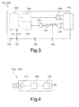
- a transceiver 110, 210 includes an antenna 310, a first and second pre-amplifier 320, 330, at least one mixer 340, a baseband-filter 350, a modulator 360, a demodulator 370 and a processing unit 390.
- the transceivers 110, 210 include a first to fourth communication port 390-393.
- the explanation of the transceivers 110, 210 should start based on a signal received by the antenna 310. As explained above, this signal could be the first and second audio signal a 1 (t), a 2 (t) or the measurement signals m 1 (t), m 2 (t).
- the received signal is amplified by the second pre-amplifier 330 and provided to the mixer 340 and the baseband unit 350.
- the transceivers 110, 210 also allow to output the pre-amplified received signal via the fourth communication port 393. In case of the transceiver 110a, 110b in the headset 100 this port may be connected to received signal strength indicator filters 120a, 120b for deriving the amplitude values A 1 , A 2 .
- the mixer 340 and the baseband filter unit 350 transforms the pre-amplified received signal into a baseband signal. This procedure is well known to a skilled person and should not be described in further detail.
- the baseband signal is now provided to the demodulator 370 demodulating the baseband signal to digital bits in the physical layer according to the OSI-model.
- the transceivers 110, 210 also allow to output the baseband signal via the third communication port 392. In case of the transceiver 110a, 110b in the headset 100 this port may be connected to received signal strength indicator filters 120a, 120b for deriving the amplitude values A 1 , A 2 .
- the advantage of deriving the amplitude values A 1 , A 2 is that baseband signal strength indicators are less sensitive to out-of-band interferences.
- the digital bits according to the physical layer in the OSI-model are finally provided to the processing unit 380 transforming the bits into a data stream according to the seventh layer in the OSI-model.
- This data stream could be either the audio stream a[k] provided via the first communication port 390 or the measurement streams m 1 [k], m 2 [k] provided via the second communication port 391 depending in which device (headset 100 or console 200) the transceiver is implemented.
- the first and second communication ports 390, 391 are implemented bidirectional. In other words, these ports can not only output a data stream provided from the processing unit 380 but also input a data stream to be provided to the processing unit. In this case, the data stream (according to the seventh layer in the OSI-model) would be converted into a bit stream according to the first layer in the OSI-model and provided to the modulator 360. This unit would modulate the bit stream onto a high-frequency signal, which is finally pre-amplified in the first pre-amplifier 320 prior transmitting via the antenna 310.
- the transceivers 110, 210 described in Fig.3 are well known to a skilled person as near-field magnetic induction transceivers. After describing the transceivers 110, 120, an embodiment for the motion tracking apparatus according to the present invention should be explained in further detail. According to the explanations above, these are the received signal strength indicator filter 120a, 120b in Fig.2 .
- Fig. 4 is an embodiment for the RSSI-filter 120a, 120b implemented in the video gaming system according to Fig.2 .
- the RSSI-filter comprises a pre-amplifier 410, a sampling unit 420 and an analog to digital converter 430, hereinafter called ADC 430.
- the preamplifier 410 receives and amplifies the audio signal a(t) in the high frequency band or in the baseband, as described in Fig.3 .
- the sampling unit 420 receives the pre-amplified first or second audio signal a 1 (t), a 2 (t) and samples amplitude values A 1 , A 2 according to a predetermined sampling rate.
- the sampling rate can be chosen depending on the technical requirements of the overall video gaming system. This may be the channel capacity available between the headset 100 and the console 200, the data processing speed in the position calculation unit 220 and/or the sensitivity with which the motion of the headset 100 should be tracked.
- the amplitude values A 1 , A 2 may be sampled as peak-to-peak values, as root-square mean values or as any other suitable value to be processed in the position calculation unit 220.
- the invention works best, if the root-square mean amplitude values of the pre-amplified first or second audio signal a 1 (t), a 2 (t) will be sampled, since these values provide the best interference immunity and therewith an optimal performance. Further, since the signal attenuation between the console 200 and the headset 100 decreased with the power of six, the best embodiment for realizing the invention is to sample the root-square mean amplitude values logarithmically, since this would provide the broadest measurement range. After sampling in the sampling unit 420, the amplitude values A 1 , A 2 are fed into the ADC 430 and transformed into the measurement data m 1 [k], m 2 [k].
- the measurement data m 1 [k], m 2 [k] including amplitude values A 1 , A 2 are finally transmitted to the console 200 and therein to the position calculation unit 220.
- the most effective transmission scheme for transmitting the measurement data m 1 [k], m 2 [k] will be time division multiplexing (TDM).
- TDM time division multiplexing
- the position of the headset 200 is calculated based on the measurement data m 1 [k], m 2 [k] - and in detail based on the amplitude values A 1 , A 2 .
- a possible calculation scheme should be shortly discussed hereinafter.
- Fig. 5 is a diagram for explaining an exemplary calculation scheme for calculating the position of headset shown in Fig.1 . This comprises the rotation angle ⁇ of the headset 100 and the distance between the headset 100 and the console 200.
- the rotation angle ⁇ should be defined.
- the rotation angle ⁇ of the headset 100 should be defined as this angle which results between an actual position and an initial position being parallel to the console 200.
- the transmission path from the left ear bud 100a to the console 200 can be described by a first distance d a .
- the transmission path from the right ear bud 100a to the console 200 can be described by a second distance d b .
- the distance between the left and right ear bud 100a, 100b can be described by d ab , wherein d ab should be constant.
- d ab should be constant.
- d a , d b ⁇ d ab The legs of the rotation angle ⁇ and the second distance d b together form a triangle, which can be considered as being rectangular based on the simplification according to equation (1).
- the rotation angle ⁇ is very small.
- the sinus-function could be approximated by a linear function.
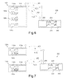
- Fig. 6 is a detailed diagram of the video system shown in Fig.1 and including a motion tracking apparatus according to a second embodiment of the present invention.
- Fig.2 is a detailed diagram of the video system shown in Fig.1 and including a motion tracking apparatus according to a second embodiment of the present invention.
- equal features as in the embodiment shown in Fig.2 are provided with the same reference signs and should not be mentioned in further detail hereinafter.
- the motion tracking apparatus is distributed over the headset 100 and the console 200.
- the second embodiment includes one transceiver 250 having two different antennas for transmitting the first audio signal a 1 (t) and the second audio signal a 2 (t) independent to each other.
- the headset 100 includes a common transceiver 110 for receiving the first and second audio signal a 1 (t), a 2 (t) and providing the first audio data a 1 [k] to the right ear bud 130a and the second audio data a 2 [k] to the left ear bud 130b.
- the common transceiver 110 provides the first and second audio signal a 1 (t), a 2 (t) itself to the received signal strength indicator filters 120a, 120b. These filters may be realized by different units as shown in the present embodiment or by a single unit.
- the measurement data m 1 [k], m 2 [k] may be transmitted within the different measurement signals m 1 (t), m 2 (t) back to different antennas of the transceiver 250, as shown in the present embodiment.
- the measurement data m 1 [k], m 2 [k] may be included into one single motion signal. This may have the advantage, that the motion signal can now be protected against transmission errors by antenna diversity.
- Fig. 7 is a detailed diagram of the video system shown in Fig.1 and including a motion tracking apparatus according to a third embodiment of the present invention.
- the third embodiment of the motion tracking apparatus is a combination of the first and second embodiment.
- the console 200 is taken from the second embodiment of the motion tracking apparatus.
- the headset 100a, 100b is taken from the first embodiment.
- the motion tracking apparatus is operated with four different antennas. That is, in the present embodiment, there is not only a distance between the antennas at one of the receiving side or the transmitting side of the audio signals a 1 (t), a 2 (t) but on both, the receiving side and the transmitting side. This allows to introduce one more information into the calculation of the position in space of the headset 100a, 100b. This information can be used to calculate one further position information as for example the head inclination of the user using the headset 100a, 100b.
- the only pre-requirement is, that the antennas on the transmitting side and the antennas on the receiving side are arranged on lines standing to each other in a skew way.
- the motion tracking apparatus may include calibration means for correcting inaccuracies. These may occur due to misalignment of the antennas, antenna spread, gain spread, received signal strength indicator measurement spread or the like. These calibration means makes sure, that there is a defined basis for the audio signals a 1 (t), a 2 (t) based on which distortions like the above discussed damping of the audio signals a 1 (t), a 2 (t) can be detected and quantized as measurement data within the measurement data m 1 [k], m 2 [k].
- the motion tracking apparatus is a light weight, cost effective and technically simple solution to determine the position of an object, as e.g. the distance and rotation of the object relative to a reference object. It is proposed to verify the propagation of a signal via at least two different transmission paths and to determine the position of the object according to the different characteristics of the transmission paths based on that signal.
- the amount of transmission paths to be considered depends on the amount of dimensions which should be considered to determine the position of the object.
Landscapes
- Physics & Mathematics (AREA)
- Engineering & Computer Science (AREA)
- Acoustics & Sound (AREA)
- Signal Processing (AREA)
- Mobile Radio Communication Systems (AREA)
Abstract
The present invention proposes an apparatus for sensing a position p[k] of a monitor object (100) located relative to a reference object (200). The position p[k] is provided in form of measurement data m1[k], m2[k]. Therein, the apparatus (120a, 120b) includes measurement means for measuring at least a first characteristic of a first transmission path (s1) and a second characteristic of a second transmission path (s2) based on at least one signal a(t), wherein the first and second transmission path connecting the monitor object (100) and the reference object (200) for signal transmission are at least partly spaced to each other, and for generating the measurement data m1[k], m2[k] based on at least the first and second characteristics. The first and second characteristics are preferably a signal damping or a signal delay. The present invention further proposes a multimedia system utilizing the motion tracking apparatus (120a, 120b) according to the invention and a method to determine the position p[k] of an object (100). The motion tracking apparatus according to the invention is technically simple, light weighting and cost effective.
Description
- The invention relates to an Apparatus for motion tracking and to a method for determining the position or orientation of a monitor object in relation to a reference object. Further, it relates to a multimedia system applying the motion tracking apparatus.
- Electronic output apparatuses enable a user to receive multimedia data from a signal processing unit. As for example, an electronic output apparatus may be a speaker or a monitor. The signal processing unit may be a video, HIFI or game console. In this technical field, there is a high economical demand on the relevant market (game industry, medical audiovisual aids, ...) and a high variety of technical development potentialities.
- Exemplary, the hardware for playing a video game could be roughly divided into a game console as signal processing unit and an input/output unit including the electronic output apparatus. Therein, the input/output unit may be a vibrating joystick sensing input data from the user to control a game and outputting vibration signals dependent on the state of the game. Game console and input/output unit communicate with each other during their operation. Since this communication can include a large amount of data to be exchanged, both units require a powerful internal operation and an effective communication port.
- In the video game, the input/output unit must be able to simulate the reality as close as possible. Therefore, motion tracking apparatuses have been proposed to track the movement of a user and to make the game play dependent on his movement.
- The very first motion tracking apparatuses were realized as head set including a head tracker, which senses the movement of the player's head based on transducers like accelerometers, gyroscopes, magnetometers, etc and provides it as input data to the console. On the other side, the console calculates multimedia data based on input data and provides it as output data to speakers included in the headset.
- However, existing headsets for motion tracking are expensive, bulky and require a high input power. This is an important reason why motion trackers are still not used in e.g. portable game consoles. The main reason for the foregoing disadvantages are conventional transducers included in conventional motion tracking apparatuses. Further, even with a combination of conventional transducers and complex mathematics, it is still not possible to provide the most significant information completely (i.e. head rotation and distance relative to the console).
-
US 6,532,291 describes a headset including a rotational acceleration sensor as head tracker. The data measured by the head tracker are wirelessly transmitted from the headset to a console. On the other hand, the multimedia data to be presented by speakers are transmitted cable bounded from the console to the headset. Thus, head tracking and multimedia communication are two different electronic systems. Due to a high power consumption, a cable connection between the headset and the console is essential to provide a sufficient long operation time of the headset. The headset provides the head rotation angle respectively only to the z-axis. However, effective motion tracking requires the rotation angle and the displacement respectively to all coordinate axes. In the prior art, this could be achieved only by including further transducers increasing the complexity of the system and therewith the power consumption and the production costs. - Therefore, it is an object of the present invention to reduce the technical complexity of a motion tracking apparatus.
- The inventor recognized, that signals will be modified differently if they pass different transmission paths. A transmission path is characterized by a transmitter for sending a signal as a start point and a receiver for picking up the signal. Since the signals are modified based on the transmission path, the characteristics of the transmission path can be used to determine the distance between a transmitter and a receiver. This distance can be used to determine the position in space of a monitor object. Such a monitor object may be a headset of a user to determine to position of its head. Based on the amount of dimensions for the position in space to be determined, two or three different distances between a reference object and this monitor object are necessary. Thus, the characteristics of two or three different transmission channels must be determined at first. Once, these characteristics are known, the position in space may be directly derived or derived via the distances as mentioned above. Thus, the invention is based on the thought to determine the characteristics of at least two different transmission paths between a reference object located relatively to a monitor object. Once these characteristics are known, all necessary information to calculate the position in space of the monitor object is available.
- Therefore, the invention proposes an apparatus to provide measurement data for determining the position in space of a monitor object located relatively to a reference object. According to the invention, the motion tracking apparatus determines a signal distortion or channel characteristic of at least a first and a second transmission path based on a predetermined signal characteristic of at least one signal as the measurement data. The first and second transmission paths are located between the monitor object and the reference object and are at least partly spaced to each other.
- Since the signal distortion is a direct indicator for the characteristics of the first and second transmission path, the motion tracking apparatus according to the present invention is able to determine distances of the first and second transmission paths between the monitor object and the reference object and therewith the position in space of the monitor object. Thus, the motion tracking apparatus not requires any further bulky sensors for determining an acceleration or the like for determining the position in space of the monitor object. Therefore, the motion tracking apparatus can be realized by a light-weighting signal processing unit without further heavy sensors requiring a high operational power. Thus, the motion tracking apparatus can be embodied cost effective, handy and with low power consumption. Therefore, the present invention provides a low complex motion tracking apparatus.
- Multimedia applications like video games and HiFi-applications require light weight motion tracking apparatuses to increase the users experience in enjoying the multimedia application. Thus, the monitor object may preferably be a headset and the reference object may preferably be a multimedia device providing video and/or sound depending on the position of the monitor object. Since the motion tracking apparatus according to the present invention does not require any heavy transducer as sensor for capturing the motion of the monitor object, the weight is drastically reduced and therefore very suitable to be applied in multimedia applications, even if the multimedia application is portable.
- The signal distortions may be determined based on the damping and/or the signal delay on the transmission paths. These are technically the most simple measures for determining a signal distortion.
- The signal distortions may be determined based on one signal, which is transmitted via the first and via the second transmission path. This would save signal bandwidth.
- In a preferred embodiment, the monitor object may be a headset including a left and a right ear bud. Each ear bud may include an autonomous wireless device placed in or over an ear of a user or listener. Unlike to conventional headsets including ear buds that are physically wired together, the present embodiment includes ear buds that receive signals independently to each other. As already explained, conventional headsets for motion tracking include bulky and cost intensive sensors for motion tracking mounted additionally on the headset. In contrary thereto, a headset including the motion tracking apparatus according to the present invention uses merely basic electronic elements but no additional sensors for determining a position of the headset. This reduces the weight of the overall headset. Such a light weight headset is important for a player, since it enables a user to feel the movement of its head very realistic without feeling the weight of the sensor included in the headset. A further advantage is that the costs are minimal in respect to motion tracking apparatuses including conventional position sensors.
- The motion tracking apparatus can be further improved, if the signal required to determine the position of the monitor object is used to transmit the usual data traffic within the electronic system applying the motion tracking apparatus, e.g. audio or video data. The signal may be a media stream, in particular a modulated multimedia stream. Since the signal for determining the position based on the channel characteristic is derived from the normal data traffic of the electronic system using the motion tracking apparatus, the transmission of an extra signal for determining the position can be omitted saving frequency bandwidth on the one hand and hardware to transmit the signal on the other hand. Therefore, the complexity of the motion tracking apparatus is drastically reduced.
- In a preferred embodiment the motion tracking apparatus is integrated it into existing systems without any further amendments on the existing system operating wirelessly. Such systems include at least a first receiver and a second receiver locally displaced to each other. These receivers are used in the motion tracking apparatus, wherein each receiver receives the signal independently to each other. Since the first and second receivers are locally displaced to each other, a signal transmitted from a signal source is received in the first and second receiver over the two different transmission paths. Thus, a first and second transmission path is realized without the need to amend the system into which the motion tracking apparatus should be integrated. The only requirement is to send the measurement data back to the transmitting source. Therein, the position of the monitor object could be calculated based on the measurement data.
- The signals or measurement data, which needs to be evaluated to determine the position of the monitor object include a lot of suitable indicators, like power strength and signal delay. However, as known to a skilled person, the signal strength in the near field of the signal reference object will be weakened with the power of six in respect to the length of the transmission path. Thus, the motion tracking apparatus preferably determines and measures at least one signal strength indicator indicating a signal amplitude of the received signal as the measurement data. By that means, the length or distance of each transmission path between the monitor object and the reference object could be determined up to some centimeters without high measurement errors. The further determination of the position of the monitor object can then be performed based on elementary mathematics. Thus, by measuring the signal amplitude, the motion tracking apparatus can be further simplified.
- Some amplitude measurement procedures to determine the amplitude of a signal, are very prone to interferences, e.g. peak-peak amplitude determination. Therefore, the motion tracking apparatus may determine the root-mean-square amplitude of the signal. The measurement of the root-mean-square amplitude is very immune to interferences such that the present embodiment provides an optimal performance of the motion tracking apparatus.
- Due to the non-linear dependency of the amplitude in respect to the length of the transmission path, the amplitude would fluctuate strongly in case of long transmission paths. In case of short transmission paths, the amplitude would keep nearly constant. This would lead to a limited measurement range for the signal amplitude. Therefore, the signal amplitude may be measured logarithmically. Since, the signal strength in the near field of the signal reference object will be weakened with the power of six in respect to the length of the transmission path, the logarithmical measurement would provide a more constant measurement accuracy in a wide measurement range as the signal amplitude is increased.
- The light weight of many electronic applications applying the motion tracking apparatus requires that the electronic component into which the motion tracking apparatus is implemented would comprise as less additional components as necessary. Thus, the motion tracking apparatus may transmit the measurement data back to the source of the signal for further data processing. Since the motion tracking apparatus is usually implemented into an input/output unit of a multimedia application being the monitor object, the real data processing for determining the position can be performed only by a console being the reference object. By postponing the measurement data back to the console as early as possible, the technical complexity of the motion tracking apparatus is kept minimal, which further reduces the overall weight.
- By re-transmitting the measurement data back to the signal source, the present invention requires a bidirectional communication. This could be achieved in its simplest form via two forward paths and to backward paths. However, it is also possible to reduce the number of required paths to two and to use a path in a multiplexing way, e.g. in time division multiplexing way. This requires at least three independent logical transmission channels, two for providing the signal to the motion tracking apparatus and for measuring the measurement data for determining the position of the monitor object and one logical channel for returning the measurement data back to the signal source. Two of the channels, namely to receive the signal and to transmit the measurement data, may be realized by time division multiplexing. This would reduce the occupied signal bandwidth and the physical interferences between the signals.
- To keep the communication traffic between the monitor object and the reference object as low as possible, the motion tracking apparatus may sub-sample, filter and/or compress the measurement data after deriving the measurement data. By doing this, the amount of measurement data to be transmitted back can be adapted to the requirements of the overall system. Criteria for the sub-sampling factors can be the channel quality, the required measurement data to unambiguously determine the position of the monitor object and/or the actual state of the monitor object (e.g. in case the monitor object is moving, provide a lower sub-sampling rate that in case the monitor object is stopping).
- The motion tracking apparatus can be implemented in a plurality of electronic components, e.g. the monitor object, the reference object or an independent third object. However, the invention works best, if the motion tracking apparatus is included in the monitor object, since the requirements for signal transmission and the number of paths in this embodiment are minimal.
- The present invention further proposes a multimedia system for providing multimedia data on a multimedia output device depending on a motion of the multimedia output device. This multimedia system includes a multimedia transmitter, e.g. a console and a multimedia receiver, e.g. a headset. The multimedia transmitter wirelessly transmits the multimedia data to the multimedia receiver. The multimedia receiver includes a motion tracking apparatus as described above and wirelessly transmits measurement data back to the multimedia transmitter based on the multimedia data.
- In a preferred embodiment, the multimedia transmitter may be a game console, since the present invention is very suitable for video game systems, wherein the motion tracking apparatus is used as input unit for receiving input data from a player for the game play.
- The multimedia receiver may determine a relative rotation angle β of the multimedia receiver based on the measurement data and the spatial distance dab between the first and second transmission path, since this determination can be performed based on elementary mathematics.
- One possibility may be to determine the length da of the first transmission path and the length db of the second transmission path, such that the relative rotation angle β would result into the equation

- The object is further solved by a method for sensing a position of a monitor object based on measurement data including information about the position of the monitor object located relative to a reference object, the method comprises the steps of: determining a characteristic of at least a first transmission path and a second transmission path arranged between the monitor object and the reference object, wherein the first and second transmission path are located between the monitor object and the reference object and at least partly spaced to each other; and calculating measurement data at least based on the determined characteristics and calculating the position of the monitor object based on the measurement data.
- The invention will be described in greater detail hereinafter, by way of nonlimiting examples, with reference to the embodiments shown in the drawings.
-
Fig. 1 is a video gaming system including a motion tracking apparatus according to the present invention; -
Fig. 2 is a detailed diagram of the video system shown inFig.1 and including a motion tracking apparatus according to a first embodiment of the present invention; -
Fig. 3 is an embodiment for a near-field magnetic induction transceiver implemented in the video gaming system according toFig.2 ; -
Fig. 4 is an embodiment for a received signal strength indicator filter implemented in the video gaming system according toFig.2 ; -
Fig. 5 is a diagram for explaining an exemplary calculation scheme for calculating the position of the headset shown inFig.1 ; -
Fig. 6 is a detailed diagram of the video system shown inFig.1 and including a motion tracking apparatus according to a second embodiment of the present invention; and -
Fig. 7 is a detailed diagram of the video system shown inFig.1 and including a motion tracking apparatus according to a third embodiment of the present invention. - The motion tracking apparatus according to the present invention could be implemented into a plurality of different systems. Examples are medical applications like hearing aids, HiFi-applications like amplifiers for providing music depending on the listener's position or input/output units for video games. In the following detailed description, the principle of the motion tracking apparatus according to the present invention should be explained based on a video gaming system.
-
Fig. 1 is a video gaming system including a motion tracking apparatus according to the present invention. The video system includes aheadset 100 and agame console 200 wirelessly connected to each other. Theheadset 100 receives an audio signal a(t) from theconsole 200 including audio data to be presented to a user. On the other hand, theconsole 200 receives a measurement or motion signal m(t) from theheadset 100 including information about the position of theheadset 100. - The
headset 100 representing the monitor object receives the audio signal a(t) and derives based thereon information about its own position. These information are then included into the measurement signal m(t) and transmitted back to theconsole 200 or any other processing means able to calculate a position of theheadset 100 based on the measurement data. The derived information can be each suitable information, which allows theconsole 200 to unambiguously determine the position in an arbitrary coordinate system. Examples for the derived information may be Cartesian, cylindrical or sphere coordinates or relative information about a position change of theheadset 100. Further examples are signal characteristics of the audio signal a(t) depending on the position of theheadset 100. As described later, in the preferred embodiment the measurement signal m(t) includes amplitude values of the audio signal a(t) received at different receivers having different positions at theheadset 100. - The
headset 100 is not limited to mere headphones. It can be enhanced by glasses including a monitor to provide pictures to the user depending on the position of its head. In this case, the signal a(t) would include audio and video data to be presented to the user. - The
console 200 may be a personal computer, which provides the audio data via the audio signal a(t) to theheadset 100. The video data are presented on an extern monitor indicated inFig.1 . It should be outlined, that even if the present embodiment shows a personal computer asconsole 200, the motion tracking apparatus according to the present invention especially allows to realize miniaturized video gaming systems. Thus, the present invention is especially suitable forconsoles 200 being portable electronic devices. -
Fig. 2 represents a detailed diagram of the video system shown inFig.1 including a motion tracking apparatus according to a first embodiment of the present invention. Theheadphone 100 includes aleft ear bud 100a and aright ear bud 100b. Bothear buds transceiver unit filter audio actuators left ear bud 100a receives via thetransceiver 110a an audio signal a(t) from theconsole 200 and transmits via thetransceiver 110a a first measurement signal m1(t) to theconsole 200. Both signals a(t), m1(t) are transmitted and received via a first transmission path s1. Accordingly, theright ear bud 100b receives via thetransceiver 110b the audio signal a(t) from theconsole 200 and transmits via thetransceiver 110b a second measurement signal m2(t) to theconsole 200. These signals a(t), m2(t) are transmitted and received via a second transmission path s2. - Thus, in contrast to conventional wireless headphones, where the left and the right ear bud receive an audio signal via a common wireless transceiver unit, the
ear buds headphone 100 according to the present embodiment receive the audio signal a(t) via two autonomouswireless transceiver units console 200 includes atransceiver 210 transmitting the audio signal a(t) to the left andright ear bud right ear bud headset 100. Moreover, theconsole 200 includes aposition calculator 220 receiving measurement data m1[k], m2[k] from thetransceiver 210, agame application 240 receiving position data p[k] from theposition calculator 220 and anaudio encoder 230 receiving a stereo audio stream as[k] from thegame application 240. Theaudio encoder 230 provides an encoded and/or modulated audio signal a(t) to thetransceiver 210. - The detailed explanation of the video system shown in
Figs.1 and 2 should be started at thegame application 240, which provides the stereo audio stream as[k] to theaudio encoder 230. The stereo audio stream as[k] depends on the game running in thegame application 240. In other words, the user can influence the stereo audio stream as[k] by its movement measured and determined by means of the motion tracking apparatus according to the invention. Theaudio encoder 230 encodes stereo audio stream as[k] into an encoded audio signal a(t) including first audio data a1[k] for a first audio channel and second audio data a2[k] for a second audio channel. The audio signal a(t) is provided to the left andright ear bud audio encoder 230 are well known for a skill person and should therefore not be explained further. Thetransceiver 210 prepares the audio signal a(t) for the wireless transmission to theear buds transceiver 210 in theconsole 200 transmits the audio signal a(t) to thetransceivers right ear bud - The transceivers in the left and
right ear bud left ear bud 100a reconstructs the encoded audio stream a[k] from a first audio signal a1(t) received via the first transmission path s1. Theright ear bud 100a reconstructs the encoded audio stream from a second audio signal a2(t) received via the second transmission path s2. Next, the audio data a1[k], a2[k] are filtered from the encoded audio stream a[k] and provided torespective loudspeakers right ear bud - In the second task, the first and second audio signals a1(t), a2(t) are respectively provided to the RSSI-
filters transceivers right ear bud transceiver 210 of theconsole 200. Finally, thetransceivers right ear bud transceiver 210 in theconsole 200. - After receiving, the
transceiver 210 in theconsole 200 reconstructs the measurement data m1[k], m2[k] from the measurement signals m1(t), m2(t) and provides it to theposition calculator 220. Based on the amplitude values A1, A2 included in the measurement data m1[k], m2[k] theposition calculator 220 determines the position data p[k] according a mathematical equation, which should be described later. Finally, the position data p[k] are provided to thegame application 240 and the above described procedure restarts. - Thus, the RSSI-
filters right ear bud - Since the video gaming apparatus considers the transmission of the audio signal a(t) via the first and second transmission path s1, s2, the position and motion of the
headset 100 can only be determined in two dimensions. This might be the distance betweenheadset 100 andconsole 200, and the rotation angle β of theheadset 200. However, it is possible to use further transmission paths to theheadset 100 to enable the determination of the position of theheadset 100 even in three dimensions. - Alternatively, it is also possible to arrange in each ear bud a data source instead of the RSSI-
filters console 200. Theconsole 200 receive both signals and determines the measurement data m1[k], m2[k] based on the amplitudes of the signals derived from the data source in the head set and transmitted via thetransceivers - Summarized, there is a plurality of variations to achieve the effect of the invention. It must only be assured that a signal with a predetermined characteristic is transmitted via at least two different transmission paths.
-
Fig. 3 is an embodiment fortransceivers Fig.2 . Thereafter, atransceiver antenna 310, a first andsecond pre-amplifier mixer 340, a baseband-filter 350, amodulator 360, ademodulator 370 and aprocessing unit 390. Further, thetransceivers - The explanation of the
transceivers antenna 310. As explained above, this signal could be the first and second audio signal a1(t), a2(t) or the measurement signals m1(t), m2(t). The received signal is amplified by thesecond pre-amplifier 330 and provided to themixer 340 and thebaseband unit 350. Thetransceivers fourth communication port 393. In case of thetransceiver headset 100 this port may be connected to received signalstrength indicator filters mixer 340 and thebaseband filter unit 350 transforms the pre-amplified received signal into a baseband signal. This procedure is well known to a skilled person and should not be described in further detail. The baseband signal is now provided to thedemodulator 370 demodulating the baseband signal to digital bits in the physical layer according to the OSI-model. Thetransceivers third communication port 392. In case of thetransceiver headset 100 this port may be connected to received signalstrength indicator filters processing unit 380 transforming the bits into a data stream according to the seventh layer in the OSI-model. This data stream could be either the audio stream a[k] provided via thefirst communication port 390 or the measurement streams m1[k], m2[k] provided via thesecond communication port 391 depending in which device (headset 100 or console 200) the transceiver is implemented. - The first and
second communication ports processing unit 380 but also input a data stream to be provided to the processing unit. In this case, the data stream (according to the seventh layer in the OSI-model) would be converted into a bit stream according to the first layer in the OSI-model and provided to themodulator 360. This unit would modulate the bit stream onto a high-frequency signal, which is finally pre-amplified in thefirst pre-amplifier 320 prior transmitting via theantenna 310. - The
transceivers Fig.3 are well known to a skilled person as near-field magnetic induction transceivers. After describing thetransceivers 110, 120, an embodiment for the motion tracking apparatus according to the present invention should be explained in further detail. According to the explanations above, these are the received signalstrength indicator filter Fig.2 . -
Fig. 4 is an embodiment for the RSSI-filter Fig.2 . The RSSI-filter comprises apre-amplifier 410, asampling unit 420 and an analog todigital converter 430, hereinafter calledADC 430. - The
preamplifier 410 receives and amplifies the audio signal a(t) in the high frequency band or in the baseband, as described inFig.3 . Thesampling unit 420 receives the pre-amplified first or second audio signal a1(t), a2(t) and samples amplitude values A1, A2 according to a predetermined sampling rate. The sampling rate can be chosen depending on the technical requirements of the overall video gaming system. This may be the channel capacity available between theheadset 100 and theconsole 200, the data processing speed in theposition calculation unit 220 and/or the sensitivity with which the motion of theheadset 100 should be tracked. The amplitude values A1, A2 may be sampled as peak-to-peak values, as root-square mean values or as any other suitable value to be processed in theposition calculation unit 220. However, the invention works best, if the root-square mean amplitude values of the pre-amplified first or second audio signal a1(t), a2(t) will be sampled, since these values provide the best interference immunity and therewith an optimal performance. Further, since the signal attenuation between theconsole 200 and theheadset 100 decreased with the power of six, the best embodiment for realizing the invention is to sample the root-square mean amplitude values logarithmically, since this would provide the broadest measurement range. After sampling in thesampling unit 420, the amplitude values A1, A2 are fed into theADC 430 and transformed into the measurement data m1[k], m2[k]. - The measurement data m1[k], m2[k] including amplitude values A1, A2 are finally transmitted to the
console 200 and therein to theposition calculation unit 220. The most effective transmission scheme for transmitting the measurement data m1[k], m2[k] will be time division multiplexing (TDM). In theposition calculation unit 220, the position of theheadset 200 is calculated based on the measurement data m1[k], m2[k] - and in detail based on the amplitude values A1, A2. A possible calculation scheme should be shortly discussed hereinafter. -
Fig. 5 is a diagram for explaining an exemplary calculation scheme for calculating the position of headset shown inFig.1 . This comprises the rotation angle β of theheadset 100 and the distance between theheadset 100 and theconsole 200. - First, the rotation angle β should be defined. The rotation angle β of the
headset 100 should be defined as this angle which results between an actual position and an initial position being parallel to theconsole 200. - The transmission path from the
left ear bud 100a to theconsole 200 can be described by a first distance da. The transmission path from theright ear bud 100a to theconsole 200 can be described by a second distance db. The distance between the left andright ear bud 
The legs of the rotation angle β and the second distance db together form a triangle, which can be considered as being rectangular based on the simplification according to equation (1). Thus, the sinus of the rotation angle β is given as:
- For further simplifying the calculation of the rotation angle, it should be assumed that the rotation angle β is very small. For small angles, the sinus-function could be approximated by a linear function. Thus, the rotation angles β apply:

The distance between theheadset 100 and theconsole 200 applies as the medium value between the first and second distance da, db:
-
Fig. 6 is a detailed diagram of the video system shown inFig.1 and including a motion tracking apparatus according to a second embodiment of the present invention. Therein, equal features as in the embodiment shown inFig.2 are provided with the same reference signs and should not be mentioned in further detail hereinafter. - Synchronously to the first embodiment, the motion tracking apparatus according to the second embodiment is distributed over the
headset 100 and theconsole 200. However, the second embodiment includes onetransceiver 250 having two different antennas for transmitting the first audio signal a1(t) and the second audio signal a2(t) independent to each other. Theheadset 100 includes acommon transceiver 110 for receiving the first and second audio signal a1(t), a2(t) and providing the first audio data a1[k] to theright ear bud 130a and the second audio data a2[k] to theleft ear bud 130b. Further, thecommon transceiver 110 provides the first and second audio signal a1(t), a2(t) itself to the received signalstrength indicator filters - The measurement data m1[k], m2[k] may be transmitted within the different measurement signals m1(t), m2(t) back to different antennas of the
transceiver 250, as shown in the present embodiment. Alternatively, the measurement data m1[k], m2[k] may be included into one single motion signal. This may have the advantage, that the motion signal can now be protected against transmission errors by antenna diversity. -
Fig. 7 is a detailed diagram of the video system shown inFig.1 and including a motion tracking apparatus according to a third embodiment of the present invention. - The third embodiment of the motion tracking apparatus is a combination of the first and second embodiment. Therein, the
console 200 is taken from the second embodiment of the motion tracking apparatus. In contrary thereto, theheadset - In the present embodiment, the motion tracking apparatus is operated with four different antennas. That is, in the present embodiment, there is not only a distance between the antennas at one of the receiving side or the transmitting side of the audio signals a1(t), a2(t) but on both, the receiving side and the transmitting side. This allows to introduce one more information into the calculation of the position in space of the
headset headset - In a further embodiment, not shown in the Figures, the motion tracking apparatus may include calibration means for correcting inaccuracies. These may occur due to misalignment of the antennas, antenna spread, gain spread, received signal strength indicator measurement spread or the like. These calibration means makes sure, that there is a defined basis for the audio signals a1(t), a2(t) based on which distortions like the above discussed damping of the audio signals a1(t), a2(t) can be detected and quantized as measurement data within the measurement data m1[k], m2[k].
- The motion tracking apparatus according to the present invention is a light weight, cost effective and technically simple solution to determine the position of an object, as e.g. the distance and rotation of the object relative to a reference object. It is proposed to verify the propagation of a signal via at least two different transmission paths and to determine the position of the object according to the different characteristics of the transmission paths based on that signal. The amount of transmission paths to be considered depends on the amount of dimensions which should be considered to determine the position of the object.
Claims (15)
- Apparatus for sensing a position p[k] of a monitor object (100) relative to a reference object (200), wherein the position p[k] is provided in form of measurement data m1[k], m2[k], wherein the monitor object (100) and the reference object (200) are connected via a first and second transmission path (s1, s2) for signal transmission and the first and second transmission path (s1, s2) are at least partly spaced to each other, the apparatus (120a, 120b) adapted to- measure at least one characteristic of the first transmission path (s1) and at least one characteristic of the second transmission path (s2) based on at least one signal a(t) transmitted via the first and second transmission path (s1, s2), and- generate the measurement data m1[k], m2[k] based on at least the characteristics,- provides the measurement data m1[k], m2[k] to a position determination means (220).
- Apparatus according to claim 1, wherein the characteristics are a signal damping or a signal delay.
- Apparatus according to claim 1 or 2, wherein the characteristic of the first transmission path (s1) and the characteristic of the second transmission path (s2) measured by the apparatus is the same or the same but at different points in time.
- Apparatus according to one of the claims 1-3, wherein the monitor object (100) is a headset and the reference object (200) is a multimedia device providing video and/or sound depending on the position p[k] of the monitor object (100).
- Apparatus according to one of the claims 1-4, wherein the signal a(t) is a media stream including audio and/or video information.
- Apparatus according to one of the claims 1-5, further including at least a first receiver (110a) and a second receiver (110b) locally displaced to each other, wherein the first receiver (110a) is adapted to receive the signal a(t) via the first transmission path (s1) and the second receiver (110b) is adapted to receive the signal a(t) via the second transmission path (s2).
- Apparatus according to one of the claims 1-6, which is adapted to determine at least one signal strength indicator indicating a signal amplitude of the received signal as the measurement data m1[k], m2[k] and to compare the determined signal strength indicator with a predetermined signal strength indicator, wherein the determination of the signal strength indicator includes preferably to determine a root-mean-square amplitude of the received signal.
- Apparatus according to one of the claims 1-7, further including sending means for sending the measurement data m1[k], m2[k] back to receiving means included in the transmitting source of the signal a(t) or to other receiving means for further data processing preferably for determining the position of the monitor object (100).
- Apparatus according to one of the claims 1-8, which is adapted to receive the signal a(t) via the at least first and second transmission path (s1, s2) and/or to send the measurement data m1[k], m2[k] based on time division multiplexing.
- Apparatus according to one of the claims 1-9, further including means for sub-sampling, for filtering and/or compressing the measurement data m1[k], m2[k] prior sending.
- Apparatus according to one of the claims 1-8, wherein the apparatus (120a, 120b) for motion tracking is included in the monitor object (100) and the transmitting source for transmitting the signal a(t) via the at least first and second transmission path (s1, s2) is included in the reference object (200), wherein the position determination means (220) is included in the monitor object (100) or in the reference object (200).
- Multimedia system for providing multimedia data in a signal a(t) on a multimedia output device (100) depending on a motion p[k] of the multimedia output device (100), the multimedia system includes:- a multimedia transmitter (200) adapted to wirelessly transmit the signal a(t) to the multimedia output device (100);- the multimedia output device (100) including an apparatus (120a, 120b) according to one of the claims 1-10 and adapted to wirelessly transmit the measurement data m1[k], m2[k] back to the multimedia transmitter (200) based on the signal a(t).
- Multimedia system according to claim 12, wherein the multimedia transmitter (200) or the multimedia output device (100) are adapted to determine a relative rotation angle β of the multimedia output device (100) based on the measurement data m1[k], m2[k] and a spatial distance dab between a first and second receiver (100a, 100b) included in the multimedia output device (100).
- Multimedia system according to claim 13, wherein the multimedia transmitter (200) is adapted to determine the length da of the first transmission path and the length db of the second transmission path, and to determine the relative rotation angle β based on the equation

- Method for sensing a position p[k] of a monitor object (100) based on measurement data m1[k], m2[k] including information about the position p[k] of the monitor object (100) located relative to a reference object (200), the method comprises the steps of:- determining a characteristic of at least a first transmission path (s1) and a second transmission path (s2) arranged between the monitor object (100) and the reference object (200), wherein the first and second transmission path (s1, s2) are located between the monitor object (100) and the reference object (200) and at least partly spaced to each other; and- calculating measurement data m1[k], m2[k] at least based on the determined characteristics;- calculating the position of the monitor object (100) based on the measurement data m1[k], m2[k].
Priority Applications (2)
| Application Number | Priority Date | Filing Date | Title |
|---|---|---|---|
| EP08158385A EP2136577A1 (en) | 2008-06-17 | 2008-06-17 | Motion tracking apparatus |
| PCT/IB2009/052076 WO2009153677A1 (en) | 2008-06-17 | 2009-05-19 | Motion tracking apparatus |
Applications Claiming Priority (1)
| Application Number | Priority Date | Filing Date | Title |
|---|---|---|---|
| EP08158385A EP2136577A1 (en) | 2008-06-17 | 2008-06-17 | Motion tracking apparatus |
Publications (1)
| Publication Number | Publication Date |
|---|---|
| EP2136577A1 true EP2136577A1 (en) | 2009-12-23 |
Family
ID=39620225
Family Applications (1)
| Application Number | Title | Priority Date | Filing Date |
|---|---|---|---|
| EP08158385A Ceased EP2136577A1 (en) | 2008-06-17 | 2008-06-17 | Motion tracking apparatus |
Country Status (2)
| Country | Link |
|---|---|
| EP (1) | EP2136577A1 (en) |
| WO (1) | WO2009153677A1 (en) |
Families Citing this family (2)
| Publication number | Priority date | Publication date | Assignee | Title |
|---|---|---|---|---|
| KR20120065774A (en) * | 2010-12-13 | 2012-06-21 | 삼성전자주식회사 | Audio providing apparatus, audio receiver and method for providing audio |
| DE102012208118A1 (en) * | 2012-05-15 | 2013-11-21 | Eberhard-Karls-Universität Tübingen | Headtracking headset and device |
Citations (5)
| Publication number | Priority date | Publication date | Assignee | Title |
|---|---|---|---|---|
| GB2203315A (en) * | 1986-02-11 | 1988-10-12 | Eliahu Igal Zeevi | Multi-phonic balancer |
| US6259795B1 (en) * | 1996-07-12 | 2001-07-10 | Lake Dsp Pty Ltd. | Methods and apparatus for processing spatialized audio |
| US6532291B1 (en) | 1996-10-23 | 2003-03-11 | Lake Dsp Pty Limited | Head tracking with limited angle output |
| US20040156512A1 (en) * | 2003-02-11 | 2004-08-12 | Parker Jeffrey C. | Audio system and method |
| WO2007112756A2 (en) * | 2006-04-04 | 2007-10-11 | Aalborg Universitet | System and method tracking the position of a listener and transmitting binaural audio data to the listener |
-
2008
- 2008-06-17 EP EP08158385A patent/EP2136577A1/en not_active Ceased
-
2009
- 2009-05-19 WO PCT/IB2009/052076 patent/WO2009153677A1/en not_active Ceased
Patent Citations (5)
| Publication number | Priority date | Publication date | Assignee | Title |
|---|---|---|---|---|
| GB2203315A (en) * | 1986-02-11 | 1988-10-12 | Eliahu Igal Zeevi | Multi-phonic balancer |
| US6259795B1 (en) * | 1996-07-12 | 2001-07-10 | Lake Dsp Pty Ltd. | Methods and apparatus for processing spatialized audio |
| US6532291B1 (en) | 1996-10-23 | 2003-03-11 | Lake Dsp Pty Limited | Head tracking with limited angle output |
| US20040156512A1 (en) * | 2003-02-11 | 2004-08-12 | Parker Jeffrey C. | Audio system and method |
| WO2007112756A2 (en) * | 2006-04-04 | 2007-10-11 | Aalborg Universitet | System and method tracking the position of a listener and transmitting binaural audio data to the listener |
Also Published As
| Publication number | Publication date |
|---|---|
| WO2009153677A1 (en) | 2009-12-23 |
Similar Documents
| Publication | Publication Date | Title |
|---|---|---|
| US5696831A (en) | Audio reproducing apparatus corresponding to picture | |
| US7272073B2 (en) | Method and device for generating information relating to the relative position of a set of at least three acoustic transducers | |
| US8160265B2 (en) | Method and apparatus for enhancing the generation of three-dimensional sound in headphone devices | |
| CA2295092C (en) | System for producing an artificial sound environment | |
| JP2022062282A (en) | Gain control in spatial audio systems | |
| US7602921B2 (en) | Sound image localizer | |
| US11812235B2 (en) | Distributed audio capture and mixing controlling | |
| US11140509B2 (en) | Head-tracking methodology for headphones and headsets | |
| JP2019535216A5 (en) | ||
| EP2731358A1 (en) | A sound system and a method for providing sound | |
| WO2001067814A3 (en) | System and method for optimization of three-dimensional audio | |
| US20050259832A1 (en) | Sound pickup method and apparatus, sound pickup and reproduction method, and sound reproduction apparatus | |
| JP2002209300A (en) | Sound image localization device, conference device using the sound image localization device, mobile phone, audio reproduction device, audio recording device, information terminal device, game machine, communication and broadcasting system | |
| EP2153689A1 (en) | Human body sound transmission system and method using single sound source | |
| EP2136577A1 (en) | Motion tracking apparatus | |
| EP3565278B1 (en) | Audio modification system and method thereof | |
| JP4705349B2 (en) | Wireless microphone system, audio transmission / reproduction method, wireless microphone transmitter, audio transmission method, and program | |
| JP2014020849A (en) | Measurement system and measurement method | |
| CN117912474B (en) | Audio codec device, method and system with sound source directional function | |
| EP2874412A1 (en) | A signal processing circuit | |
| JP4150319B2 (en) | Headphone device | |
| US20260006397A1 (en) | Acoustic wave analysis method, system and device applied to spatial audio | |
| JP3552273B2 (en) | Headphone equipment | |
| JP2629296B2 (en) | Sound signal reproduction method | |
| KR101228643B1 (en) | Apparatus and method for motion detection, and apparatus for audio and image gerneration |
Legal Events
| Date | Code | Title | Description |
|---|---|---|---|
| PUAI | Public reference made under article 153(3) epc to a published international application that has entered the european phase |
Free format text: ORIGINAL CODE: 0009012 |
|
| AK | Designated contracting states |
Kind code of ref document: A1 Designated state(s): AT BE BG CH CY CZ DE DK EE ES FI FR GB GR HR HU IE IS IT LI LT LU LV MC MT NL NO PL PT RO SE SI SK TR |
|
| AX | Request for extension of the european patent |
Extension state: AL BA MK RS |
|
| STAA | Information on the status of an ep patent application or granted ep patent |
Free format text: STATUS: THE APPLICATION HAS BEEN REFUSED |
|
| 18R | Application refused |
Effective date: 20100204 |