EP2136525A1 - Method, device and base station for generating protocol data unit - Google Patents
Method, device and base station for generating protocol data unit Download PDFInfo
- Publication number
- EP2136525A1 EP2136525A1 EP08715017A EP08715017A EP2136525A1 EP 2136525 A1 EP2136525 A1 EP 2136525A1 EP 08715017 A EP08715017 A EP 08715017A EP 08715017 A EP08715017 A EP 08715017A EP 2136525 A1 EP2136525 A1 EP 2136525A1
- Authority
- EP
- European Patent Office
- Prior art keywords
- pdu
- sdu
- segmentation
- length
- indicator field
- Prior art date
- Legal status (The legal status is an assumption and is not a legal conclusion. Google has not performed a legal analysis and makes no representation as to the accuracy of the status listed.)
- Granted
Links
Images


Classifications
-
- H—ELECTRICITY
- H04—ELECTRIC COMMUNICATION TECHNIQUE
- H04W—WIRELESS COMMUNICATION NETWORKS
- H04W80/00—Wireless network protocols or protocol adaptations to wireless operation
- H04W80/02—Data link layer protocols
-
- H—ELECTRICITY
- H04—ELECTRIC COMMUNICATION TECHNIQUE
- H04L—TRANSMISSION OF DIGITAL INFORMATION, e.g. TELEGRAPHIC COMMUNICATION
- H04L9/00—Cryptographic mechanisms or cryptographic arrangements for secret or secure communications; Network security protocols
- H04L9/40—Network security protocols
-
- H—ELECTRICITY
- H04—ELECTRIC COMMUNICATION TECHNIQUE
- H04L—TRANSMISSION OF DIGITAL INFORMATION, e.g. TELEGRAPHIC COMMUNICATION
- H04L1/00—Arrangements for detecting or preventing errors in the information received
- H04L1/004—Arrangements for detecting or preventing errors in the information received by using forward error control
- H04L1/0056—Systems characterized by the type of code used
- H04L1/0071—Use of interleaving
-
- H—ELECTRICITY
- H04—ELECTRIC COMMUNICATION TECHNIQUE
- H04L—TRANSMISSION OF DIGITAL INFORMATION, e.g. TELEGRAPHIC COMMUNICATION
- H04L1/00—Arrangements for detecting or preventing errors in the information received
- H04L1/0078—Avoidance of errors by organising the transmitted data in a format specifically designed to deal with errors, e.g. location
- H04L1/0083—Formatting with frames or packets; Protocol or part of protocol for error control
-
- H—ELECTRICITY
- H04—ELECTRIC COMMUNICATION TECHNIQUE
- H04W—WIRELESS COMMUNICATION NETWORKS
- H04W28/00—Network traffic management; Network resource management
- H04W28/02—Traffic management, e.g. flow control or congestion control
- H04W28/06—Optimizing the usage of the radio link, e.g. header compression, information sizing, discarding information
-
- H—ELECTRICITY
- H04—ELECTRIC COMMUNICATION TECHNIQUE
- H04W—WIRELESS COMMUNICATION NETWORKS
- H04W88/00—Devices specially adapted for wireless communication networks, e.g. terminals, base stations or access point devices
- H04W88/08—Access point devices
-
- H—ELECTRICITY
- H04—ELECTRIC COMMUNICATION TECHNIQUE
- H04W—WIRELESS COMMUNICATION NETWORKS
- H04W28/00—Network traffic management; Network resource management
- H04W28/02—Traffic management, e.g. flow control or congestion control
- H04W28/06—Optimizing the usage of the radio link, e.g. header compression, information sizing, discarding information
- H04W28/065—Optimizing the usage of the radio link, e.g. header compression, information sizing, discarding information using assembly or disassembly of packets
Definitions
- the present invention generally relates to a field of mobile communication, and in particular to a method and apparatus for generating a PDU and a base station thereof, which may be applied in the Single Frequency Network (SFN) to recover multiple packets lost during the transmission of service data so as to ensure contents synchronization between different base stations.
- SFN Single Frequency Network
- eNB base stations
- eNB In a wireless network transmission system adopting a SFN technology, for example, in a Multimedia Broadcast and Multicast (MBMS) system of LTE, all base stations (hereinafter referred to as eNB) totally keep synchronous in both time and frequency. In this way, if each eNB transmits the same data at one starting point and adopts the same physical layer modulation and coding technologies, in the space transmission, each signal sent from respective eNBs has the same waveform.
- UE user equipment
- signals received by the UEs are all useful signals carrying the same data
- such a technology may significantly reduce interferences coming from neighboring cells (because signals coming from the neighboring cells here are all useful signals, rather than interferences), thus may be applied in some broadcast and multicast systems.
- such a SFN technology may be applied in the MBMS system of LTE.
- Fig. 1 shows a network topology for the LTE MBMS.
- Network elements supporting MBMS mainly include Broadcast/ Multicast Service Center (BM-SC), SAE GateWay (SAE GW), eNB and UE.
- BM-SC Broadcast/ Multicast Service Center
- SAE GW SAE GateWay
- eNB UE
- S1 interface an interface between a UE and an eNB.
- BM-SC is adapted to perform an authorization, initiate a MBMS bearer service in the PLMN, and transmit MBMS data in accordance with a preset schedule.
- SAE GW controls the MBMS bearer service for the user, and transmits the MBMS data to E-UTRAN.
- the eNB is responsible for transmitting the MBMS data to an air interface of a designated MBMS service area with high efficiency.
- Fig. 2 shows a schematic diagram of a network structure for the SFN.
- each base station is covered with the same frequency point, and it is unnecessary to perform time multiplexing, frequency multiplexing, or code multiplexing between cells.
- One service is assigned with the same time and frequency resources in any area covered by the base stations. Since the same physical layer modulation and coding technologies are applied, each signal carrying the same data sent from respective base stations has the same waveform. In view of the receiver of the UE, the signal looks like to be sent from one base station, just with some multi-paths having large time delay.
- the SFN may be fully covered with normal transmission powers of all base stations or improved transmission powers of a part of base stations.
- the wireless interface protocol layer is divided into three layers.
- the bottom layer is Physical Layer (L1), above which a Data Link Layer (L2) and Network Layer are involved.
- L1 Physical Layer
- L2 Data Link Layer
- L3 The Network Layer (L3) provides Radio Resource Control (RRC) function.
- RRC Radio Resource Control
- IP data packets arrive at respective eNBs, and each IP data packet has a variable length, for example, ranging from tens of byes to 1500 bytes.
- packet loss recovery means filling pseudo data into a wireless link control buffer without recovering real data in the packet, since the contents synchronization for the transmissions of respective packets can be ensured after the packet loss as long as the eNB knows the length of the packet to be transmitted.
- Fig. 3 shows a relationship between RLC SDU (Service Data Unit) and RLC PDU (Protocol Data Unit) in the existing unicast situation, in which each segmentation has a length indicator.
- RLC SDU Service Data Unit
- RLC PDU Protocol Data Unit
- Fig. 4 shows a distribution of byte length for the two lost packets.
- one of the lost two packets is of 400 bytes
- the other one is of 200 bytes
- they are divided, in together, into three segmentations, each of which is indicated using respective LIs in different PDUs.
- Fig. 5 shows another distribution of byte length for the two lost packets.
- one of the lost two packets is of 298 bytes
- the other one is of 302 bytes, and they respectively serve as one segmentation, thereby forming two segmentations in total, each of which is indicated using respective LIs in different PDUs.
- the eNB can not know the distribution of byte length for respective packets in case of multiple packets loss, and the lost packets can not be correctly recovered, thus leading to the contents de-synchronization at the eNB. Moreover, the contents de-synchronization would affect contents synchronization of subsequent packets. In a word, using the unicast RLC PDU format can not recover lost packets at the eNB but easily leading to the contents de-synchronization.
- the object of the present invention is to provide a method and apparatus for generating a PDU and a base station thereof, with which multiple packets lost during the service data transmission can be recovered so as to keep contents transmission synchronization between different base stations.
- the method, apparatus and base station proposed by embodiments of the present invention are also applied in the unicast transmission.
- a method for generating a PDU comprising steps of: segmenting an input SDU into at least one segmentation in such a manner that the at least one segmentation is distributed in at least one PDU; and setting an offset field and at least one length indicator field in a header of each PDU, wherein the offset field indicates an offset of a first segmentation of a first new SDU appearing in the PDU, and the length indicator field indicates a total length of the new SDU.
- a method for generating a PDU comprising steps of: segmenting an input SDU into at least one segmentation in such a manner that the at least one segmentation is distributed in at least one PDU; and setting at least one length indicator field in a header of each PDU, wherein the length indicator field indicates a length of the last segmentation of the at least one segmentation.
- an apparatus for generating a PDU comprising: a segmentation unit adapted to segment an input SDU into at least one segmentation in such a manner that the at least one segmentation is distributed in at least one PDU; a calculation unit adapted to calculate an offset of a first segmentation of a first new SDU appearing in the PDU; and a setting unit adapted to set an offset field and at least one length indicator field in a header of each PDU, wherein the offset field indicates an offset of a first segmentation of a new SDU appearing in the PDU, and the length indicator field indicates a total length of the new SDU.
- an apparatus for generating a PDU comprising: a segmentation unit adapted to segment an input SDU into at least one segmentation in such a manner that the at least one segmentation is distributed in at least one PDU; a calculation unit adapted to calculate a length of the last segmentation of the at least one segmentation; and a setting unit adapted to set at least one length indicator field in a header of each PDU, wherein the length indicator field indicates a length of the last segmentation of the at least one segmentation.
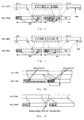
- Fig. 6A shows an example of data format constructing a PDU according to the first embodiment of the present invention.
- one OFFSET field and at least one LI field are set in a header of each PDU.
- the OFFSET field indicates an offset of a first segmentation of a first new SDU appearing in the PDU.
- Each RLC PUD only has one OFFSET field. If a first segmentation of one SDU starts just after one LI field, a value of the OFFSET field will be set to 0.
- the LI field indicates a total length of a new SDU. If there are a plurality of new SDUs in the PDU, there are a plurality of LI fields.
- the LI field has a length of two bytes
- the OFFSET field has a length of two bytes.
- the reason for setting the OFFSET field lies in that if a UE at a receiver side finds one PDU has been lost, it may find a starting point of a next new SDU based on the OFFSET field, otherwise, the receiver can not find a starting point of a complete SDU if there is no OFFSET field.
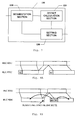
- Fig. 7 shows a functional block diagram of an apparatus for generating a PDU according to the first embodiment of the present invention.
- the apparatus 100 comprises a segmentation unit 110, an offset calculation unit 120 and a setting unit 130.
- the segmentation unit 110 receives a RLC SDU input externally and segments the received RLC SDU in accordance with a preset length for RLC PDU, so as to construct different PDUs.
- the calculation unit 120 calculates an offset position for respective new SDU segmentations to be filled in the PDU, for example a position number in the data transmission stream.
- the setting unit 130 writes the position number calculated by the offset calculation unit 120 into an OFFSET field and then writes a length of a corresponding SDU into a LI field.
- Fig. 8A shows an example of data format constructing PDU according to the second embodiment of the present invention.
- a LI field included in a header of the data format according to the second embodiment of the present invention, but no OFFSET field.
- the LI field here has a value indicating the end of SDU in one PDU, i.e. a length of the last segmentation of one SDU.
- the previous byte of next RLC SDU is also filled into the end of the RLC PDU, as shown in Fig. 8B . In this case, it is needed to fill the LI of the SDU segmentation into the posterior RLC PDU. Otherwise, i.e. if the length of the last SDU segmentation is equal to the vacancy in the RLC PDU, it is also needed to fill the LI of the SDU segmentation into the posterior RLC PDU. Also, the LI field is filled with a reserved value.
- the following table shows reserved values for specific LIs in some special cases and corresponding explanations.
- Bits Descriptions 0000,0000,0000,000 The previous RLC PDU is exactly filled with the last segmentation of an RLC SDU, and there is no LI that indicates the end of the RLC SDU in the previous RLC PDU. 0100,0000,0000,000
- the last segmentation of an RLC SDU is one more byte more of exactly filling the previous RLC PDU, and there is no LI that indicates the end of the RLC SDU in the previous RLC PDU.
- the remaining one byte in the previous RLC PDU is the first byte of next RLC PDU.
- the last segmentation of an RLC SDU is one more byte more of exactly filling the previous RLC PDU, and there is no LI that indicates the end of the RLC SDU in the previous RLC PDU.
- the remaining one byte in the previous RLC PDU is ignored. 1100,0000,0000,000
- the remaining byte in the current RLC PDU is a padding byte.
- FIG. 9 shows a functional block diagram of an apparatus for generating a PDU according to the second embodiment of the present invention.
- an apparatus 200 comprises a segmentation unit 210, a calculation unit 220 and a setting unit 230.
- the segmentation unit 200 receives a RLC SDU input externally and segments the received RLC SDU based on a preset length for RLC PDU, so as to construct different PDUs.
- the calculation unit 220 calculates a length of the last segmentation of the respective segmentations segmented in the current SDU.
- the setting unit 230 writes the length calculated by the calculation section 220 into a LI field.
- Figs. 10 A and 10B respectively show schematic diagram of recovery for different distributions of byte lengths for two lost packets according to the second embodiment of the present invention.
- the eNB only knows that there are two packets lost and the total length of the two packets is of 600 bytes, but not the length distribution of the lost two packets in the lost 600 bytes.
- Fig. 10A shows one distribution of byte length for two lost packets.
- one of the lost two packets is of 400 bytes, the other one is of 200 bytes, and they are divided, in together, into three segmentations.
- only the segments in the posterior PDU are indicated with LIs.
- Fig. 10B shows another distribution of byte length for two lost packets.
- one of the lost two packets is of 298 bytes
- the other one is of 302 bytes
- RLC PDU format for the unicast is the same with the formats for the PDUs generated by the methods and apparatuses according to the first embodiment and the second embodiment, except that there is no need to consider the packet recovering in the unicast transmission.
- LI is set for one segment of respective SDUs when constructing RLC PDU in such a manner that each SDU only has one LI even if the SDU is segmented into a plurality of SDU segmentations. If a length indicator LI is placed before the first segmentation of the SDU, an offset field and at least one LI field are set in a header of each PDU, the offset field indicating an offset of a first segmentation of a first new SDU appearing in the PDU, and the LI field indicating a total length of the new SDU. If a length indicator LI is placed before the last segmentation of the SDU, at least one LI field is set in a header of each PDU, the LI field indicating a length of the last SDU segmentation.
Landscapes
- Engineering & Computer Science (AREA)
- Computer Networks & Wireless Communication (AREA)
- Signal Processing (AREA)
- Computer Security & Cryptography (AREA)
- Mobile Radio Communication Systems (AREA)
- Communication Control (AREA)
- Data Exchanges In Wide-Area Networks (AREA)
Abstract
Description
- The present invention generally relates to a field of mobile communication, and in particular to a method and apparatus for generating a PDU and a base station thereof, which may be applied in the Single Frequency Network (SFN) to recover multiple packets lost during the transmission of service data so as to ensure contents synchronization between different base stations.
- In a wireless network transmission system adopting a SFN technology, for example, in a Multimedia Broadcast and Multicast (MBMS) system of LTE, all base stations (hereinafter referred to as eNB) totally keep synchronous in both time and frequency. In this way, if each eNB transmits the same data at one starting point and adopts the same physical layer modulation and coding technologies, in the space transmission, each signal sent from respective eNBs has the same waveform. At a user equipment (hereinafter referred to as UE) side, data sent from the eNBs may be considered as a signal sent from one eNB. Since signals received by the UEs are all useful signals carrying the same data, such a technology may significantly reduce interferences coming from neighboring cells (because signals coming from the neighboring cells here are all useful signals, rather than interferences), thus may be applied in some broadcast and multicast systems. For example, such a SFN technology may be applied in the MBMS system of LTE.
-
Fig. 1 shows a network topology for the LTE MBMS. Network elements supporting MBMS mainly include Broadcast/ Multicast Service Center (BM-SC), SAE GateWay (SAE GW), eNB and UE. In general, an interface between a UE and an eNB is called as S1 interface. - As an entry for contents provider, BM-SC is adapted to perform an authorization, initiate a MBMS bearer service in the PLMN, and transmit MBMS data in accordance with a preset schedule. SAE GW controls the MBMS bearer service for the user, and transmits the MBMS data to E-UTRAN. The eNB is responsible for transmitting the MBMS data to an air interface of a designated MBMS service area with high efficiency.
-
Fig. 2 shows a schematic diagram of a network structure for the SFN. InFig. 2 , each base station is covered with the same frequency point, and it is unnecessary to perform time multiplexing, frequency multiplexing, or code multiplexing between cells. One service is assigned with the same time and frequency resources in any area covered by the base stations. Since the same physical layer modulation and coding technologies are applied, each signal carrying the same data sent from respective base stations has the same waveform. In view of the receiver of the UE, the signal looks like to be sent from one base station, just with some multi-paths having large time delay. The SFN may be fully covered with normal transmission powers of all base stations or improved transmission powers of a part of base stations. - In the LTE wireless communication system, the wireless interface protocol layer is divided into three layers. The bottom layer is Physical Layer (L1), above which a Data Link Layer (L2) and Network Layer are involved. At the wireless interface, the Data Link Layer is divided into several sub-layers, including a Media Access Control (MAC) protocol sub-layer, a Radio Link Control (RLC) protocol sub-layer, and a Packet Data Convergence Protocol (PDCP) sub-layer. The Network Layer (L3) provides Radio Resource Control (RRC) function.
- In the whole protocol, IP data packets arrive at respective eNBs, and each IP data packet has a variable length, for example, ranging from tens of byes to 1500 bytes.
- Furthermore, since there are different paths to respective eNBs, multiple packets loss will occur during the transmission. Therefore, it is critical to ensure the contents synchronization for the data sent from respective eNBs for one eMBMS service. In view of this, it is needed to achieve a simple recovery for the eNB wireless processing when there are packets lost during the data distribution to the eNBs.
- Here, packet loss recovery means filling pseudo data into a wireless link control buffer without recovering real data in the packet, since the contents synchronization for the transmissions of respective packets can be ensured after the packet loss as long as the eNB knows the length of the packet to be transmitted.
-
Fig. 3 shows a relationship between RLC SDU (Service Data Unit) and RLC PDU (Protocol Data Unit) in the existing unicast situation, in which each segmentation has a length indicator. As shown inFig. 3 , it is assumed that, at the eNB side, the RLC PDU has a size of 600 bytes, two bytes for SN and SI are included in the RLC PDU header, and each LI has a size of 2 bytes. - It can be seen from
Fig. 3 that two packets are lost at the S1 interface (SN=i, i+1). When the eNB receives a packet numbered as SN=i+3, it is known that the previous two packets have been lost. However, the eNB only knows that there are two packets lost and the total length of the packet is of 600 bytes, it does not know the length distribution of the 600 bytes in the lost two packets. -
Fig. 4 shows a distribution of byte length for the two lost packets. As shown inFig. 4 , one of the lost two packets is of 400 bytes, the other one is of 200 bytes, and they are divided, in together, into three segmentations, each of which is indicated using respective LIs in different PDUs. For example, in the previous PDU, two LIs respectively indicate 296 bytes from the SDU numbered as SN=i and 298 bytes from the SDU numbered as SN=i+1. In the posterior PDU, the three LIs respectively indicate 102 bytes from the SDU numbered as SN=i+1, 200 bytes from the SDU numbered as SN=i+2, and 290 bytes from the SDU numbered as SN=i+3. If recovery is performed following such a manner, the starting byte of the next PDU will be 1286. -
Fig. 5 shows another distribution of byte length for the two lost packets. As shown inFig. 5 , one of the lost two packets is of 298 bytes, the other one is of 302 bytes, and they respectively serve as one segmentation, thereby forming two segmentations in total, each of which is indicated using respective LIs in different PDUs. For example, in the previous PDU, two LIs respectively indicate 296 bytes from the SDU numbered as SN=i and 298 bytes from the SDU numbered as SN=i+1. In the posterior PDU, the two LIs respectively indicate 302 bytes from the SDU numbered as SN=i+2 and 292 bytes from the SDU numbered as SN=i+3. If recovery is performed following such a manner, the starting byte for the next PDU will be 1288. - It can be seen from the above examples that the de-synchronization for the RLC PDU contents will be incurred since the number of segmentations for the recovered RLC SDU numbered as SN=i+1 is different from the number of segmentations for the recovered RLC SDU numbered as SN=i+2, and each segmentation has respective LI, for example there are two LIs or three LIs.
- Consequently, since segmentations of a single SDU have respective LIs, the eNB can not know the distribution of byte length for respective packets in case of multiple packets loss, and the lost packets can not be correctly recovered, thus leading to the contents de-synchronization at the eNB. Moreover, the contents de-synchronization would affect contents synchronization of subsequent packets. In a word, using the unicast RLC PDU format can not recover lost packets at the eNB but easily leading to the contents de-synchronization.
- In view of the above problems, the object of the present invention is to provide a method and apparatus for generating a PDU and a base station thereof, with which multiple packets lost during the service data transmission can be recovered so as to keep contents transmission synchronization between different base stations. The method, apparatus and base station proposed by embodiments of the present invention are also applied in the unicast transmission.
- According to an aspect of the present invention, a method for generating a PDU is provided, comprising steps of: segmenting an input SDU into at least one segmentation in such a manner that the at least one segmentation is distributed in at least one PDU; and setting an offset field and at least one length indicator field in a header of each PDU, wherein the offset field indicates an offset of a first segmentation of a first new SDU appearing in the PDU, and the length indicator field indicates a total length of the new SDU.
- According to another aspect of the present invention, a method for generating a PDU is provided, comprising steps of: segmenting an input SDU into at least one segmentation in such a manner that the at least one segmentation is distributed in at least one PDU; and setting at least one length indicator field in a header of each PDU, wherein the length indicator field indicates a length of the last segmentation of the at least one segmentation.
- According to yet another aspect of the present invention, an apparatus for generating a PDU is provided, comprising: a segmentation unit adapted to segment an input SDU into at least one segmentation in such a manner that the at least one segmentation is distributed in at least one PDU; a calculation unit adapted to calculate an offset of a first segmentation of a first new SDU appearing in the PDU; and a setting unit adapted to set an offset field and at least one length indicator field in a header of each PDU, wherein the offset field indicates an offset of a first segmentation of a new SDU appearing in the PDU, and the length indicator field indicates a total length of the new SDU.
- According to yet another aspect of the present invention, an apparatus for generating a PDU is provided, comprising: a segmentation unit adapted to segment an input SDU into at least one segmentation in such a manner that the at least one segmentation is distributed in at least one PDU; a calculation unit adapted to calculate a length of the last segmentation of the at least one segmentation; and a setting unit adapted to set at least one length indicator field in a header of each PDU, wherein the length indicator field indicates a length of the last segmentation of the at least one segmentation.
- With the above methods and apparatus proposed by embodiments of the present invention, since a single SDU is indicated only using one LI even if it is segmented into a plurality of segmentations, and the LI indicates the end of SDU in one PDU, it is ensured that an eNB in the SFN can recover packets in case of multiple packets loss while avoiding the de-synchronization during the contents transmission.
- The above objects, advantages and features of the present invention will be apparent from the following detailed description on the preferred embodiments taken conjunction with the drawings in which:
-
Fig.1 shows a network topology for LTE MBMS; -
Fig. 2 shows a schematic diagram of a network structure for the SFN; -
Fig. 3 shows a relationship between RLC SDU and RLC PDU in the existing unicast situation; -
Fig. 4 shows one distribution of byte length for two lost packets; -
Fig. 5 shows another distribution of byte length for two lost packets; -
Fig. 6A shows one example of data format constructing PDU according to a first embodiment of the present invention; -
Fig. 6B shows another example of data format constructing PDU according to the first embodiment of the present invention; -
Fig. 7 shows a functional block diagram of an apparatus for generating a PDU according to the first embodiment of the present invention; -
Fig. 8A shows one example of data format constructing PDU according to a second embodiment of the present invention; -
Fig. 8B shows another example of data format constructing PDU according to the second embodiment of the present invention; -
Fig. 9 shows a functional block diagram of an apparatus for generating a PDU according to the second embodiment of the present invention; -
Fig. 10A is a schematic diagram of recovery for one distribution of byte length for two lost packets according to the second embodiment of the present invention; -
Fig. 10B is a schematic diagram of recovery for another distribution of byte length for two lost packets according to the second embodiment of the present invention; - Hereinafter, a detailed description will be given to the embodiments of the present invention with reference to the figures. In the description, the elements or functions unnecessary to the description of the present invention will be omitted in order not to obscure the present invention.
-
Fig. 6A shows an example of data format constructing a PDU according to the first embodiment of the present invention. - As shown in
Fig. 6A , one OFFSET field and at least one LI field are set in a header of each PDU. The OFFSET field indicates an offset of a first segmentation of a first new SDU appearing in the PDU. Each RLC PUD only has one OFFSET field. If a first segmentation of one SDU starts just after one LI field, a value of the OFFSET field will be set to 0. Moreover, the LI field indicates a total length of a new SDU. If there are a plurality of new SDUs in the PDU, there are a plurality of LI fields. Here, the LI field has a length of two bytes, and the OFFSET field has a length of two bytes. - The reason for setting the OFFSET field lies in that if a UE at a receiver side finds one PDU has been lost, it may find a starting point of a next new SDU based on the OFFSET field, otherwise, the receiver can not find a starting point of a complete SDU if there is no OFFSET field.
- In addition, if there are two or one bytes unfilled in the RLC PDU, it is needed to fill data of corresponding number of bytes of next RLC SDU into the previous RLC PDU, instead of filling LI into the previous RLC PDU. In this way, one SDU has only one LI.
Fig. 6B shows such an example. -
Fig. 7 shows a functional block diagram of an apparatus for generating a PDU according to the first embodiment of the present invention. As shown inFig. 7 , theapparatus 100 comprises asegmentation unit 110, an offsetcalculation unit 120 and asetting unit 130. - The
segmentation unit 110 receives a RLC SDU input externally and segments the received RLC SDU in accordance with a preset length for RLC PDU, so as to construct different PDUs. Thecalculation unit 120 calculates an offset position for respective new SDU segmentations to be filled in the PDU, for example a position number in the data transmission stream. Thesetting unit 130 writes the position number calculated by the offsetcalculation unit 120 into an OFFSET field and then writes a length of a corresponding SDU into a LI field. - In addition, if there are two or one bytes unfilled in the current RLC PDU, data of corresponding number of bytes (i.e. the number of unfilled bytes) of next RLC SDU will be filled into the current RLC PDU, rather than filling LI field of the next RLC PDU into the end of the current RLC PDU field.
-
Fig. 8A shows an example of data format constructing PDU according to the second embodiment of the present invention. As shown inFig. 8A , there is a LI field included in a header of the data format according to the second embodiment of the present invention, but no OFFSET field. However, the LI field here has a value indicating the end of SDU in one PDU, i.e. a length of the last segmentation of one SDU. - If the length of the last SDU segmentation is less than the vacancy in the RLC PDU by one byte, the previous byte of next RLC SDU is also filled into the end of the RLC PDU, as shown in
Fig. 8B . In this case, it is needed to fill the LI of the SDU segmentation into the posterior RLC PDU. Otherwise, i.e. if the length of the last SDU segmentation is equal to the vacancy in the RLC PDU, it is also needed to fill the LI of the SDU segmentation into the posterior RLC PDU. Also, the LI field is filled with a reserved value. - The following table shows reserved values for specific LIs in some special cases and corresponding explanations.
Bits Descriptions 0000,0000,0000,000 The previous RLC PDU is exactly filled with the last segmentation of an RLC SDU, and there is no LI that indicates the end of the RLC SDU in the previous RLC PDU. 0100,0000,0000,000 The last segmentation of an RLC SDU is one more byte more of exactly filling the previous RLC PDU, and there is no LI that indicates the end of the RLC SDU in the previous RLC PDU. The remaining one byte in the previous RLC PDU is the first byte of next RLC PDU. 1000,0000,0000,000 The last segmentation of an RLC SDU is one more byte more of exactly filling the previous RLC PDU, and there is no LI that indicates the end of the RLC SDU in the previous RLC PDU. The remaining one byte in the previous RLC PDU is ignored. 1100,0000,0000,000 The remaining byte in the current RLC PDU is a padding byte. -
Fig. 9 shows a functional block diagram of an apparatus for generating a PDU according to the second embodiment of the present invention. As shown inFig. 9 , anapparatus 200 comprises asegmentation unit 210, acalculation unit 220 and asetting unit 230. - The
segmentation unit 200 receives a RLC SDU input externally and segments the received RLC SDU based on a preset length for RLC PDU, so as to construct different PDUs. Thecalculation unit 220 calculates a length of the last segmentation of the respective segmentations segmented in the current SDU. Thesetting unit 230 writes the length calculated by thecalculation section 220 into a LI field. -
Figs. 10 A and 10B respectively show schematic diagram of recovery for different distributions of byte lengths for two lost packets according to the second embodiment of the present invention. As shown inFig. 3 , two packets (SN=I, i+1) are lost at the S1 interface. When the eNB receives the packet numbered as SN=i+3, it is known that the previous two packets have been lost. However, the eNB only knows that there are two packets lost and the total length of the two packets is of 600 bytes, but not the length distribution of the lost two packets in the lost 600 bytes. -
Fig. 10A shows one distribution of byte length for two lost packets. As shown inFig. 10A , one of the lost two packets is of 400 bytes, the other one is of 200 bytes, and they are divided, in together, into three segmentations. However, only the segments in the posterior PDU are indicated with LIs. For example, in the previous PDU, one LI indicates 296 bytes from the SDU numbered as SN=I, and there is no LI for 300 bytes from the SDU numbered as SN=i+1 based on the idea of the second embodiment of the present invention, in which only the first segmentation is indicated with LI. In the posterior PDU, the two LIs respectively indicate 100 bytes from the SDU numbered as SN=i+1 and 200 bytes from the SDU numbered as SN=i+2, and there is no LI for 294 bytes from the SDU numbered as SN=i+3 based on the idea of the second embodiment of the present invention. In this way, the total number of bytes for RLC headers, which are filled in these two RLC PDUs, including SN and LI, is
- If recovery is performed following such a manner, the starting byte of the next PDU will be

-
Fig. 10B shows another distribution of byte length for two lost packets. As shown inFig. 10B , one of the lost two packets is of 298 bytes, the other one is of 302 bytes, and they respectively serves as one segmentation, thereby forming two segmentations in total, each of which is indicated using respective LIs in different PDUs. For example, in the previous PDU, the two LIs respectively indicate 296 bytes from the SDU numbered as SN=i and 298 bytes from the SDU numbered as SN=i+1. In the posterior PDU, the LI indicates 302 bytes from the SDU numbered as SN=i+2, and there is no LI for 294 bytes from the SDU numbered as SN=i+3 based on the idea of the second embodiment of the present invention. In this way, the total number of bytes for RLC headers, which are filled in these two RLC PDUs, including SN and LI, is 4 bytes SN + 6 bytes LI = 10 bytes. - If recovery is performed following the manner mentioned above, the starting byte of the next PDU will be

- It can be seen from the above examples that no matter how the segmentations segmented in the RLC SDU numbered as SN=i+1 and the RLC SDU numbered as SN=i+2 are distributed, the RLC PDU contents synchronization will be kept on after recovering LI of 4 bytes and data of 600 bytes since an idea of "one LI per SDU" is followed here, i.e. there are only two LIs.
- Other than the MBMS, the present invention may be also applied in the unicast transmission of LTE. In this case, RLC PDU format for the unicast is the same with the formats for the PDUs generated by the methods and apparatuses according to the first embodiment and the second embodiment, except that there is no need to consider the packet recovering in the unicast transmission.
- With the present invention, LI is set for one segment of respective SDUs when constructing RLC PDU in such a manner that each SDU only has one LI even if the SDU is segmented into a plurality of SDU segmentations. If a length indicator LI is placed before the first segmentation of the SDU, an offset field and at least one LI field are set in a header of each PDU, the offset field indicating an offset of a first segmentation of a first new SDU appearing in the PDU, and the LI field indicating a total length of the new SDU. If a length indicator LI is placed before the last segmentation of the SDU, at least one LI field is set in a header of each PDU, the LI field indicating a length of the last SDU segmentation.
- Although some embodiments of the present invention have been shown and described, it will be appreciated by those skilled in the art that many improvements and changes can be made without departing from the principles and spirits of the invention which is solely defined by the following claims.
Claims (30)
- A method for generating a PDU comprising steps of:segmenting an input SDU into at least one segmentation in such a manner that the at least one segmentation is distributed in at least one PDU; and
setting an offset field and at least one length indicator field in a header of each PDU, wherein the offset field indicates an offset of a first segmentation of a first new SDU appearing in the PDU, and the length indicator field indicates a total length of the new SDU. - The method according to Claim 1, wherein if a first segmentation of one SDU, which is filled in the PDU, starts just after one length indicator field, a value of an offset field for the PDU is set to 0.
- The method according to Claim 1, wherein if there are two or one bytes unfilled in the PDU, bytes of the number of unfilled bytes of next SDU are filled into the previous PDU.
- The method according to Claim 2 or 3, wherein the length indicator field has a length of two bytes.
- The method according to Claim 2 or 3, wherein the offset field has a length of two bytes.
- A method for generating a PDU comprising steps of:segmenting an input SDU into at least one segmentation in such a manner that the at least one segmentation is distributed in at least one PDU; andsetting at least one length indicator field in a header of each PDU, wherein the length indicator field indicates a length of the last segmentation of the at least one segmentation.
- The method according to Claim 6, wherein if the length of the last segmentation of the SDU is less than vacancy in the PDU by one byte, the previous byte of next SDU is filled into the end of the PDU.
- The method according to Claim 6, wherein if the length of the last SDU segmentation is equal to vacancy in the previous PDU, the length indicator field of the segmentation is filled into the posterior PDU.
- The method according to Claim 7 or 8, wherein the length indicator field has a length of two bytes.
- The method according to Claim 7 or 8, wherein the length indicator field has a length of eleven bytes.
- The method according to Claim 7 or 8, wherein a value of the length indicator field is defined as a first reserved value for indicating that the previous PDU is exactly filled with the last segmentation of the SDU and that there is no length indicator field that indicates the end of the SDU in the previous PDU.
- The method according to Claim 7 or 8, wherein a value of the length indicator field is defined as a second reserved value for indicating that the last segmentation of the SDU is one more byte more of exactly filling the previous PDU, that there is no length indicator field that indicates the end of the SDU in the previous PDU, and that the remaining one byte in the previous PDU serves as a first byte of next PDU.
- The method according to Claim 7 or 8, wherein a value of the length indicator field is defined as a third reserved value for indicating that the last segmentation of the SDU is one more byte more of exactly filling the previous PDU, that there is no length indicator field that indicates the end of the SDU in the previous PDU, and that the remaining one byte in the previous PDU is ignored.
- The method according to Claim 7 or 8, wherein a value of the length indicator field is defined as a fourth reserved value for indicating that the remaining byte in the current PDU is a padding byte.
- An apparatus for generating a PDU comprising:a segmentation unit adapted to segment an input SDU into at least one segmentation in such a manner that the at least one segmentation is distributed in at least one PDU;a calculation unit adapted to calculate an offset of a first segmentation of a first new SDU appearing in the PDU; anda setting unit adapted to set an offset field and at least one length indicator field in a header of each PDU, wherein the offset field indicates an offset of a first segmentation of a new SDU appearing in the PDU, and the length indicator field indicates a total length of the new SDU.
- The apparatus according to Claim 15, wherein if a first segmentation of one SDU, which is filled in the PDU, starts just after one length indicator field, a value of an offset field for the PDU is set to 0.
- The apparatus according to Claim 15, wherein if there are two or one bytes unfilled in the PDU, bytes of the number of unfilled bytes of next SDU are filled into the previous PDU.
- The apparatus according to Claim 16 or 17, wherein the length indicator field has a length of two bytes.
- The apparatus according to Claim 16 or 17, wherein the offset field has a length of two bytes.
- A base station comprising the apparatus according to Claim 15.
- An apparatus for generating a PDU comprising:a segmentation unit adapted to segment an input SDU into at least one segmentation in such a manner that the at least one segmentation is distributed in at least one PDU;a calculation unit adapted to calculate a length of the last segmentation of the at least one segmentation; anda setting unit adapted to set at least one length indicator field in a header of each PDU, the length indicator field indicating a length of the last segmentation of the at least one segmentation.
- The apparatus according to Claim 21, wherein if the length of the last segmentation of the SDU is less than vacancy in the PDU by one byte, the previous byte of next SDU is filled into the end of the PDU.
- The apparatus according to Claim 21, wherein if the length of the last SDU segmentation is equal to vacancy in the previous PDU, the length indicator field of the segmentation is filled into the posterior PDU.
- The apparatus according to Claim 22 or 23, wherein the length indicator field has a length of two bytes.
- The apparatus according to Claim 23 or 24, wherein the length indicator field has a length of eleven bytes.
- The apparatus according to Claim 23 or 24, wherein a value of the length indicator field is defined as a first reserved value for indicating that the previous PDU is exactly filled with the last segmentation of the SDU and that there is no length indicator field that indicates the end of the SDU in the previous PDU.
- The apparatus according to Claim 23 or 24, wherein a value of the length indicator field is defined as a second reserved value for indicating that the last segmentation of the SDU is one more byte more of exactly filling the previous PDU, that there is no length indicator field that indicates the end of the SDU in the previous PDU, and that the remaining one byte in the previous PDU serves as a first byte of next PDU.
- The apparatus according to Claim 23 or 24, wherein a value of the length indicator field is defined as a third reserved value for indicating that the last segmentation of the SDU is one more byte more of exactly filling the previous PDU, that there is no length indicator field that indicates the end of the SDU in the previous PDU, and that the remaining one byte in the previous PDU is ignored.
- The apparatus according to Claim 23 or 24, wherein a value of the length indicator field is defined as a fourth reserved value for indicating that the remaining byte in the current PDU is a padding byte.
- A base station comprising the apparatus according to Claim 21.
Applications Claiming Priority (2)
| Application Number | Priority Date | Filing Date | Title |
|---|---|---|---|
| CN200710038488A CN101272519B (en) | 2007-03-21 | 2007-03-21 | Method, device and base station for generating protocol data unit |
| PCT/CN2008/000565 WO2008113265A2 (en) | 2007-03-21 | 2008-03-21 | Method, device and base station for generating protocol data unit |
Publications (3)
| Publication Number | Publication Date |
|---|---|
| EP2136525A1 true EP2136525A1 (en) | 2009-12-23 |
| EP2136525A4 EP2136525A4 (en) | 2011-08-03 |
| EP2136525B1 EP2136525B1 (en) | 2016-01-06 |
Family
ID=39766527
Family Applications (1)
| Application Number | Title | Priority Date | Filing Date |
|---|---|---|---|
| EP08715017.3A Active EP2136525B1 (en) | 2007-03-21 | 2008-03-21 | Method, device and base station for generating protocol data unit |
Country Status (6)
| Country | Link |
|---|---|
| US (1) | US9756680B2 (en) |
| EP (1) | EP2136525B1 (en) |
| JP (1) | JP5121854B2 (en) |
| KR (1) | KR101554857B1 (en) |
| CN (1) | CN101272519B (en) |
| WO (1) | WO2008113265A2 (en) |
Families Citing this family (16)
| Publication number | Priority date | Publication date | Assignee | Title |
|---|---|---|---|---|
| FR2943882A1 (en) * | 2009-03-27 | 2010-10-01 | Thomson Licensing | TRANSMITTING METHOD FOR WIRELESS NETWORK AND CORRESPONDING RECEPTION METHOD |
| BRPI0924671A2 (en) * | 2009-06-22 | 2016-01-26 | Alcatel Lucent | Method and apparatus for controlling downlink data synchronization in an embms transmission |
| BR112012004798B1 (en) | 2009-09-02 | 2021-09-21 | Apple Inc | BUILDING MAC PACKAGE DATA UNIT FOR WIRELESS SYSTEMS |
| US9414409B2 (en) | 2012-02-06 | 2016-08-09 | Samsung Electronics Co., Ltd. | Method and apparatus for transmitting/receiving data on multiple carriers in mobile communication system |
| CN104272616B (en) * | 2012-03-19 | 2018-02-16 | 三星电子株式会社 | Method and apparatus for reporting power headroom in mobile communication system supporting carrier aggregation |
| CN103581168B (en) * | 2013-08-02 | 2016-06-22 | 中国科学技术大学苏州研究院 | Hidden information communication means based on IP fragmentation camouflage |
| CN104702576B (en) * | 2013-12-09 | 2018-02-09 | 腾讯科技(深圳)有限公司 | Voice transmission method, device and voice service system |
| EP3395029B1 (en) * | 2015-12-23 | 2021-03-17 | Nokia Solutions and Networks Oy | Methods, apparatuses and computer program product for pdu formatting according to sdu segmentation |
| WO2017188698A1 (en) * | 2016-04-27 | 2017-11-02 | Lg Electronics Inc. | Method and device for receiving data unit |
| WO2017211417A1 (en) * | 2016-06-09 | 2017-12-14 | Nokia Solutions And Networks Oy | Real-time segmentation |
| CN108012289B (en) * | 2016-11-01 | 2022-11-22 | 中兴通讯股份有限公司 | PDU (protocol data Unit) sending method and device and PDU receiving method and device |
| ES3062009T3 (en) * | 2016-11-04 | 2026-04-08 | Beijing Xiaomi Mobile Software Co Ltd | Method and device for generating protocol data unit (pdu) packet |
| EP3782343B1 (en) * | 2018-04-19 | 2023-02-15 | Telefonaktiebolaget Lm Ericsson (Publ) | Apparatuses and methods for handling data packets |
| WO2024007327A1 (en) * | 2022-07-08 | 2024-01-11 | Zte Corporation | Method of resource efficiency improvement |
| KR20250042776A (en) * | 2022-07-30 | 2025-03-27 | 후아웨이 테크놀러지 컴퍼니 리미티드 | Multi-user EDMG Aggregate PPDU Structure |
| WO2024162640A1 (en) * | 2023-01-31 | 2024-08-08 | Samsung Electronics Co., Ltd. | Method and apparatus for handling segmentation in a wireless communication |
Family Cites Families (8)
| Publication number | Priority date | Publication date | Assignee | Title |
|---|---|---|---|---|
| FI106504B (en) * | 1998-10-06 | 2001-02-15 | Nokia Networks Oy | Procedure for segmenting data in a telecommunications system |
| KR100447162B1 (en) * | 2000-08-19 | 2004-09-04 | 엘지전자 주식회사 | Method for length indicator inserting in protocol data unit of radio link control |
| US8880709B2 (en) * | 2001-09-12 | 2014-11-04 | Ericsson Television Inc. | Method and system for scheduled streaming of best effort data |
| US8233462B2 (en) * | 2003-10-15 | 2012-07-31 | Qualcomm Incorporated | High speed media access control and direct link protocol |
| KR100913900B1 (en) * | 2005-05-04 | 2009-08-26 | 삼성전자주식회사 | Method and apparatus for transmitting and receiving packet data using predefined length indicator in mobile communication system |
| CN100574330C (en) * | 2005-08-09 | 2009-12-23 | 中兴通讯股份有限公司 | Method for sending and receiving unacknowledged mode protocol data unit in wireless link layer |
| EP1764980B8 (en) * | 2005-09-20 | 2009-01-07 | Panasonic Corporation | Method and apparatus for packet segmentation and concatenation signaling in a communication system |
| US8503423B2 (en) * | 2007-02-02 | 2013-08-06 | Interdigital Technology Corporation | Method and apparatus for versatile MAC multiplexing in evolved HSPA |
-
2007
- 2007-03-21 CN CN200710038488A patent/CN101272519B/en active Active
-
2008
- 2008-03-21 WO PCT/CN2008/000565 patent/WO2008113265A2/en not_active Ceased
- 2008-03-21 EP EP08715017.3A patent/EP2136525B1/en active Active
- 2008-03-21 JP JP2009553893A patent/JP5121854B2/en active Active
- 2008-03-21 US US12/531,784 patent/US9756680B2/en active Active
- 2008-03-21 KR KR1020097021508A patent/KR101554857B1/en active Active
Non-Patent Citations (4)
| Title |
|---|
| "3rd Generation Partnership Project; Technical Specification Group Radio Access Network; Radio Link Control (RLC) protocol specification (Release 7)", 3GPP STANDARD; 3GPP TS 25.322, 3RD GENERATION PARTNERSHIP PROJECT (3GPP), MOBILE COMPETENCE CENTRE ; 650, ROUTE DES LUCIOLES ; F-06921 SOPHIA-ANTIPOLIS CEDEX ; FRANCE, no. V7.2.0, 1 September 2006 (2006-09-01), pages 1-80, XP050367794, * |
| ALCATEL-LUCENT: "Multiple packets loss recovery and RLC PDU format in eMBMS", 3GPP DRAFT; R2-072360, 3RD GENERATION PARTNERSHIP PROJECT (3GPP), MOBILE COMPETENCE CENTRE ; 650, ROUTE DES LUCIOLES ; F-06921 SOPHIA-ANTIPOLIS CEDEX ; FRANCE, vol. RAN WG2, no. Orlando, USA; 20070622, 22 June 2007 (2007-06-22), XP050135207, [retrieved on 2007-06-22] * |
| ALCATEL-LUCENT: "RLC PDU structure in LTE", 3GPP DRAFT; R2-070106, 3RD GENERATION PARTNERSHIP PROJECT (3GPP), MOBILE COMPETENCE CENTRE ; 650, ROUTE DES LUCIOLES ; F-06921 SOPHIA-ANTIPOLIS CEDEX ; FRANCE, vol. RAN WG2, no. Sorrento, Italy; 20070112, 12 January 2007 (2007-01-12), XP050133220, [retrieved on 2007-01-12] * |
| See also references of WO2008113265A2 * |
Also Published As
| Publication number | Publication date |
|---|---|
| US20100111110A1 (en) | 2010-05-06 |
| KR20090127350A (en) | 2009-12-10 |
| EP2136525B1 (en) | 2016-01-06 |
| CN101272519A (en) | 2008-09-24 |
| JP5121854B2 (en) | 2013-01-16 |
| JP2010521903A (en) | 2010-06-24 |
| US9756680B2 (en) | 2017-09-05 |
| WO2008113265A2 (en) | 2008-09-25 |
| KR101554857B1 (en) | 2015-09-22 |
| CN101272519B (en) | 2012-09-19 |
| EP2136525A4 (en) | 2011-08-03 |
Similar Documents
| Publication | Publication Date | Title |
|---|---|---|
| EP2136525B1 (en) | Method, device and base station for generating protocol data unit | |
| AU2008227323B2 (en) | Method for processing radio protocol in mobile telecommunications system and transmitter of mobile telecommunications | |
| EP2290863B1 (en) | Wireless communication method for transmitting a sequence of data units between a wireless device and a network | |
| US7190701B2 (en) | Wireless communication system and method having RLC layer of transparent mode | |
| US8005085B2 (en) | Method for distribution of data packets in a single frequency mobile communication network, an access network node, a base station and a single frequency mobile communication network therefor | |
| KR101635433B1 (en) | A method and apparatus for processing control message which requests retransmitting data | |
| EP2471223B1 (en) | Enhanced multiplexing for single rlc entity | |
| EP2082506B1 (en) | Method for content synchronization when broadcasting data in a wireless network | |
| US20160249252A1 (en) | Method of generating data block in wireless communication system | |
| KR101507961B1 (en) | Method and apparatus for reporting a buffer status of a terminal in a mobile communication system | |
| EP3104632A1 (en) | Communication methods executed by auxiliary base station and main base station and corresponding base stations | |
| EP1965598A1 (en) | Method of broadcasting in a telecommunications network in a segmentation re-assembly mode | |
| JP2007081883A (en) | Radio base station and user common data transmission method | |
| KR101413029B1 (en) | Method and apparatus for controlling downlink data synchronization in evolved multimedia broadcast multicast service(embms) transmission | |
| EP2227052A1 (en) | Resource allocation method and apparatus thereof | |
| CN102014339A (en) | Method, device and system for configuring multimedia broadcast multicast service (MBMS) synchronization |
Legal Events
| Date | Code | Title | Description |
|---|---|---|---|
| PUAI | Public reference made under article 153(3) epc to a published international application that has entered the european phase |
Free format text: ORIGINAL CODE: 0009012 |
|
| 17P | Request for examination filed |
Effective date: 20091019 |
|
| AK | Designated contracting states |
Kind code of ref document: A1 Designated state(s): AT BE BG CH CY CZ DE DK EE ES FI FR GB GR HR HU IE IS IT LI LT LU LV MC MT NL NO PL PT RO SE SI SK TR |
|
| DAX | Request for extension of the european patent (deleted) | ||
| A4 | Supplementary search report drawn up and despatched |
Effective date: 20110706 |
|
| RIC1 | Information provided on ipc code assigned before grant |
Ipc: H04L 1/00 20060101ALI20110630BHEP Ipc: H04L 29/06 20060101AFI20110630BHEP |
|
| RAP1 | Party data changed (applicant data changed or rights of an application transferred) |
Owner name: ALCATEL LUCENT |
|
| 17Q | First examination report despatched |
Effective date: 20120322 |
|
| 111Z | Information provided on other rights and legal means of execution |
Free format text: AT BE BG CH CY CZ DE DK EE ES FI FR GB GR HR HU IE IS IT LI LT LU LV MC MT NL NO PL PT RO SE SI SK TR Effective date: 20130410 |
|
| RAP1 | Party data changed (applicant data changed or rights of an application transferred) |
Owner name: ALCATEL LUCENT |
|
| D11X | Information provided on other rights and legal means of execution (deleted) | ||
| REG | Reference to a national code |
Ref country code: DE Ref legal event code: R079 Ref document number: 602008041798 Country of ref document: DE Free format text: PREVIOUS MAIN CLASS: H04L0029060000 Ipc: H04W0028040000 |
|
| GRAP | Despatch of communication of intention to grant a patent |
Free format text: ORIGINAL CODE: EPIDOSNIGR1 |
|
| RIC1 | Information provided on ipc code assigned before grant |
Ipc: H04W 28/06 20090101ALI20150608BHEP Ipc: H04L 1/00 20060101ALI20150608BHEP Ipc: H04W 28/04 20090101AFI20150608BHEP Ipc: H04W 80/02 20090101ALI20150608BHEP |
|
| INTG | Intention to grant announced |
Effective date: 20150702 |
|
| GRAS | Grant fee paid |
Free format text: ORIGINAL CODE: EPIDOSNIGR3 |
|
| GRAA | (expected) grant |
Free format text: ORIGINAL CODE: 0009210 |
|
| AK | Designated contracting states |
Kind code of ref document: B1 Designated state(s): AT BE BG CH CY CZ DE DK EE ES FI FR GB GR HR HU IE IS IT LI LT LU LV MC MT NL NO PL PT RO SE SI SK TR |
|
| REG | Reference to a national code |
Ref country code: GB Ref legal event code: FG4D |
|
| REG | Reference to a national code |
Ref country code: CH Ref legal event code: EP |
|
| REG | Reference to a national code |
Ref country code: IE Ref legal event code: FG4D |
|
| REG | Reference to a national code |
Ref country code: AT Ref legal event code: REF Ref document number: 769799 Country of ref document: AT Kind code of ref document: T Effective date: 20160215 |
|
| REG | Reference to a national code |
Ref country code: DE Ref legal event code: R096 Ref document number: 602008041798 Country of ref document: DE |
|
| REG | Reference to a national code |
Ref country code: FR Ref legal event code: PLFP Year of fee payment: 9 |
|
| REG | Reference to a national code |
Ref country code: LT Ref legal event code: MG4D |
|
| REG | Reference to a national code |
Ref country code: NL Ref legal event code: MP Effective date: 20160106 |
|
| REG | Reference to a national code |
Ref country code: AT Ref legal event code: MK05 Ref document number: 769799 Country of ref document: AT Kind code of ref document: T Effective date: 20160106 |
|
| PG25 | Lapsed in a contracting state [announced via postgrant information from national office to epo] |
Ref country code: NL Free format text: LAPSE BECAUSE OF FAILURE TO SUBMIT A TRANSLATION OF THE DESCRIPTION OR TO PAY THE FEE WITHIN THE PRESCRIBED TIME-LIMIT Effective date: 20160106 |
|
| PG25 | Lapsed in a contracting state [announced via postgrant information from national office to epo] |
Ref country code: NO Free format text: LAPSE BECAUSE OF FAILURE TO SUBMIT A TRANSLATION OF THE DESCRIPTION OR TO PAY THE FEE WITHIN THE PRESCRIBED TIME-LIMIT Effective date: 20160406 Ref country code: HR Free format text: LAPSE BECAUSE OF FAILURE TO SUBMIT A TRANSLATION OF THE DESCRIPTION OR TO PAY THE FEE WITHIN THE PRESCRIBED TIME-LIMIT Effective date: 20160106 Ref country code: GR Free format text: LAPSE BECAUSE OF FAILURE TO SUBMIT A TRANSLATION OF THE DESCRIPTION OR TO PAY THE FEE WITHIN THE PRESCRIBED TIME-LIMIT Effective date: 20160407 Ref country code: IT Free format text: LAPSE BECAUSE OF FAILURE TO SUBMIT A TRANSLATION OF THE DESCRIPTION OR TO PAY THE FEE WITHIN THE PRESCRIBED TIME-LIMIT Effective date: 20160106 Ref country code: FI Free format text: LAPSE BECAUSE OF FAILURE TO SUBMIT A TRANSLATION OF THE DESCRIPTION OR TO PAY THE FEE WITHIN THE PRESCRIBED TIME-LIMIT Effective date: 20160106 Ref country code: ES Free format text: LAPSE BECAUSE OF FAILURE TO SUBMIT A TRANSLATION OF THE DESCRIPTION OR TO PAY THE FEE WITHIN THE PRESCRIBED TIME-LIMIT Effective date: 20160106 |
|
| PG25 | Lapsed in a contracting state [announced via postgrant information from national office to epo] |
Ref country code: PL Free format text: LAPSE BECAUSE OF FAILURE TO SUBMIT A TRANSLATION OF THE DESCRIPTION OR TO PAY THE FEE WITHIN THE PRESCRIBED TIME-LIMIT Effective date: 20160106 Ref country code: SE Free format text: LAPSE BECAUSE OF FAILURE TO SUBMIT A TRANSLATION OF THE DESCRIPTION OR TO PAY THE FEE WITHIN THE PRESCRIBED TIME-LIMIT Effective date: 20160106 Ref country code: LT Free format text: LAPSE BECAUSE OF FAILURE TO SUBMIT A TRANSLATION OF THE DESCRIPTION OR TO PAY THE FEE WITHIN THE PRESCRIBED TIME-LIMIT Effective date: 20160106 Ref country code: AT Free format text: LAPSE BECAUSE OF FAILURE TO SUBMIT A TRANSLATION OF THE DESCRIPTION OR TO PAY THE FEE WITHIN THE PRESCRIBED TIME-LIMIT Effective date: 20160106 Ref country code: PT Free format text: LAPSE BECAUSE OF FAILURE TO SUBMIT A TRANSLATION OF THE DESCRIPTION OR TO PAY THE FEE WITHIN THE PRESCRIBED TIME-LIMIT Effective date: 20160506 Ref country code: BE Free format text: LAPSE BECAUSE OF NON-PAYMENT OF DUE FEES Effective date: 20160331 Ref country code: IS Free format text: LAPSE BECAUSE OF FAILURE TO SUBMIT A TRANSLATION OF THE DESCRIPTION OR TO PAY THE FEE WITHIN THE PRESCRIBED TIME-LIMIT Effective date: 20160506 Ref country code: LV Free format text: LAPSE BECAUSE OF FAILURE TO SUBMIT A TRANSLATION OF THE DESCRIPTION OR TO PAY THE FEE WITHIN THE PRESCRIBED TIME-LIMIT Effective date: 20160106 |
|
| REG | Reference to a national code |
Ref country code: DE Ref legal event code: R097 Ref document number: 602008041798 Country of ref document: DE |
|
| PG25 | Lapsed in a contracting state [announced via postgrant information from national office to epo] |
Ref country code: MC Free format text: LAPSE BECAUSE OF FAILURE TO SUBMIT A TRANSLATION OF THE DESCRIPTION OR TO PAY THE FEE WITHIN THE PRESCRIBED TIME-LIMIT Effective date: 20160106 Ref country code: EE Free format text: LAPSE BECAUSE OF FAILURE TO SUBMIT A TRANSLATION OF THE DESCRIPTION OR TO PAY THE FEE WITHIN THE PRESCRIBED TIME-LIMIT Effective date: 20160106 Ref country code: DK Free format text: LAPSE BECAUSE OF FAILURE TO SUBMIT A TRANSLATION OF THE DESCRIPTION OR TO PAY THE FEE WITHIN THE PRESCRIBED TIME-LIMIT Effective date: 20160106 Ref country code: LU Free format text: LAPSE BECAUSE OF FAILURE TO SUBMIT A TRANSLATION OF THE DESCRIPTION OR TO PAY THE FEE WITHIN THE PRESCRIBED TIME-LIMIT Effective date: 20160321 |
|
| REG | Reference to a national code |
Ref country code: CH Ref legal event code: PL |
|
| PLBE | No opposition filed within time limit |
Free format text: ORIGINAL CODE: 0009261 |
|
| STAA | Information on the status of an ep patent application or granted ep patent |
Free format text: STATUS: NO OPPOSITION FILED WITHIN TIME LIMIT |
|
| PG25 | Lapsed in a contracting state [announced via postgrant information from national office to epo] |
Ref country code: RO Free format text: LAPSE BECAUSE OF FAILURE TO SUBMIT A TRANSLATION OF THE DESCRIPTION OR TO PAY THE FEE WITHIN THE PRESCRIBED TIME-LIMIT Effective date: 20160106 Ref country code: SK Free format text: LAPSE BECAUSE OF FAILURE TO SUBMIT A TRANSLATION OF THE DESCRIPTION OR TO PAY THE FEE WITHIN THE PRESCRIBED TIME-LIMIT Effective date: 20160106 Ref country code: CZ Free format text: LAPSE BECAUSE OF FAILURE TO SUBMIT A TRANSLATION OF THE DESCRIPTION OR TO PAY THE FEE WITHIN THE PRESCRIBED TIME-LIMIT Effective date: 20160106 |
|
| 26N | No opposition filed |
Effective date: 20161007 |
|
| REG | Reference to a national code |
Ref country code: IE Ref legal event code: MM4A |
|
| PG25 | Lapsed in a contracting state [announced via postgrant information from national office to epo] |
Ref country code: BE Free format text: LAPSE BECAUSE OF FAILURE TO SUBMIT A TRANSLATION OF THE DESCRIPTION OR TO PAY THE FEE WITHIN THE PRESCRIBED TIME-LIMIT Effective date: 20160106 |
|
| PG25 | Lapsed in a contracting state [announced via postgrant information from national office to epo] |
Ref country code: IE Free format text: LAPSE BECAUSE OF NON-PAYMENT OF DUE FEES Effective date: 20160321 Ref country code: LI Free format text: LAPSE BECAUSE OF NON-PAYMENT OF DUE FEES Effective date: 20160331 Ref country code: CH Free format text: LAPSE BECAUSE OF NON-PAYMENT OF DUE FEES Effective date: 20160331 |
|
| PG25 | Lapsed in a contracting state [announced via postgrant information from national office to epo] |
Ref country code: SI Free format text: LAPSE BECAUSE OF FAILURE TO SUBMIT A TRANSLATION OF THE DESCRIPTION OR TO PAY THE FEE WITHIN THE PRESCRIBED TIME-LIMIT Effective date: 20160106 Ref country code: BG Free format text: LAPSE BECAUSE OF FAILURE TO SUBMIT A TRANSLATION OF THE DESCRIPTION OR TO PAY THE FEE WITHIN THE PRESCRIBED TIME-LIMIT Effective date: 20160406 |
|
| REG | Reference to a national code |
Ref country code: FR Ref legal event code: PLFP Year of fee payment: 10 |
|
| PG25 | Lapsed in a contracting state [announced via postgrant information from national office to epo] |
Ref country code: MT Free format text: LAPSE BECAUSE OF FAILURE TO SUBMIT A TRANSLATION OF THE DESCRIPTION OR TO PAY THE FEE WITHIN THE PRESCRIBED TIME-LIMIT Effective date: 20160106 |
|
| REG | Reference to a national code |
Ref country code: FR Ref legal event code: PLFP Year of fee payment: 11 |
|
| PG25 | Lapsed in a contracting state [announced via postgrant information from national office to epo] |
Ref country code: HU Free format text: LAPSE BECAUSE OF FAILURE TO SUBMIT A TRANSLATION OF THE DESCRIPTION OR TO PAY THE FEE WITHIN THE PRESCRIBED TIME-LIMIT; INVALID AB INITIO Effective date: 20080321 Ref country code: CY Free format text: LAPSE BECAUSE OF FAILURE TO SUBMIT A TRANSLATION OF THE DESCRIPTION OR TO PAY THE FEE WITHIN THE PRESCRIBED TIME-LIMIT Effective date: 20160106 |
|
| PG25 | Lapsed in a contracting state [announced via postgrant information from national office to epo] |
Ref country code: MT Free format text: LAPSE BECAUSE OF FAILURE TO SUBMIT A TRANSLATION OF THE DESCRIPTION OR TO PAY THE FEE WITHIN THE PRESCRIBED TIME-LIMIT Effective date: 20160331 Ref country code: TR Free format text: LAPSE BECAUSE OF FAILURE TO SUBMIT A TRANSLATION OF THE DESCRIPTION OR TO PAY THE FEE WITHIN THE PRESCRIBED TIME-LIMIT Effective date: 20160106 |
|
| REG | Reference to a national code |
Ref country code: DE Ref legal event code: R082 Ref document number: 602008041798 Country of ref document: DE Representative=s name: LOUIS POEHLAU LOHRENTZ PATENTANWAELTE PARTNERS, DE Ref country code: DE Ref legal event code: R082 Ref document number: 602008041798 Country of ref document: DE Representative=s name: LOUIS, POEHLAU, LOHRENTZ, DE Ref country code: DE Ref legal event code: R081 Ref document number: 602008041798 Country of ref document: DE Owner name: NOKIA TECHNOLOGIES OY, FI Free format text: FORMER OWNER: ALCATEL LUCENT, BOULOGNE BILLANCOURT, FR |
|
| REG | Reference to a national code |
Ref country code: GB Ref legal event code: 732E Free format text: REGISTERED BETWEEN 20200402 AND 20200408 |
|
| P01 | Opt-out of the competence of the unified patent court (upc) registered |
Effective date: 20230527 |
|
| PGFP | Annual fee paid to national office [announced via postgrant information from national office to epo] |
Ref country code: GB Payment date: 20260202 Year of fee payment: 19 |
|
| PGFP | Annual fee paid to national office [announced via postgrant information from national office to epo] |
Ref country code: DE Payment date: 20260204 Year of fee payment: 19 |
|
| PGFP | Annual fee paid to national office [announced via postgrant information from national office to epo] |
Ref country code: FR Payment date: 20260209 Year of fee payment: 19 |