EP2136493A1 - Audio mixing console - Google Patents
Audio mixing console Download PDFInfo
- Publication number
- EP2136493A1 EP2136493A1 EP08011209A EP08011209A EP2136493A1 EP 2136493 A1 EP2136493 A1 EP 2136493A1 EP 08011209 A EP08011209 A EP 08011209A EP 08011209 A EP08011209 A EP 08011209A EP 2136493 A1 EP2136493 A1 EP 2136493A1
- Authority
- EP
- European Patent Office
- Prior art keywords
- control
- elements
- control module
- group
- control elements
- Prior art date
- Legal status (The legal status is an assumption and is not a legal conclusion. Google has not performed a legal analysis and makes no representation as to the accuracy of the status listed.)
- Granted
Links
Images



Classifications
-
- H—ELECTRICITY
- H04—ELECTRIC COMMUNICATION TECHNIQUE
- H04H—BROADCAST COMMUNICATION
- H04H60/00—Arrangements for broadcast applications with a direct linking to broadcast information or broadcast space-time; Broadcast-related systems
- H04H60/02—Arrangements for generating broadcast information; Arrangements for generating broadcast-related information with a direct linking to broadcast information or to broadcast space-time; Arrangements for simultaneous generation of broadcast information and broadcast-related information
- H04H60/04—Studio equipment; Interconnection of studios
-
- G—PHYSICS
- G06—COMPUTING OR CALCULATING; COUNTING
- G06F—ELECTRIC DIGITAL DATA PROCESSING
- G06F3/00—Input arrangements for transferring data to be processed into a form capable of being handled by the computer; Output arrangements for transferring data from processing unit to output unit, e.g. interface arrangements
- G06F3/01—Input arrangements or combined input and output arrangements for interaction between user and computer
- G06F3/03—Arrangements for converting the position or the displacement of a member into a coded form
- G06F3/033—Pointing devices displaced or positioned by the user, e.g. mice, trackballs, pens or joysticks; Accessories therefor
- G06F3/0362—Pointing devices displaced or positioned by the user, e.g. mice, trackballs, pens or joysticks; Accessories therefor with detection of one-dimensional [1D] translations or rotations of an operating part of the device, e.g. scroll wheels, sliders, knobs, rollers or belts
Definitions
- This invention relates to control modules comprising a plurality of control elements.
- the invention relates especially but not exclusively to audio mixing consoles as an example of a control module having a plurality of control elements.
- the invention can be used in any system having a control module or a remote control. Furthermore, the invention may be applied in work station interfaces. Generally, the invention can be applied in any system where a plurality of different signals having different signal parameters should be controlled.
- One example of a control module receiving different signals with a large variety of signal parameters is an audio mixing console.
- Audio mixing consoles are used for applications such as multi track recording, broadcast, post production, live sound reinforcement and stage monitoring.
- the sound signal from microphones, electronic musical instruments or other sound sources enters the mixing console and the latter amplifies these sources as needed and allows the operator to mix them, equalize them and add effects according to the requirements of the installation.
- a plurality of control elements are provided, often configured as rotary buttons to control the different functions of the audio mixing console.
- the mixing console a large variety of different features of a sound signal can be controlled. In order to limit the number of different control elements on the mixing console, it is possible to control different functions of the audio mixing console using one control element.
- a control element In one operating mode, a control element is used for adjusting one feature of the recorded audio signal whereas in another operating mode, the same control element is used to adapt another feature of the mixing console. Furthermore, several control elements can be grouped to a group of control elements each group controlling a predetermined function of the audio signal. For the operator it can be sometimes difficult to identify where one group of control elements ends and where another group starts.
- a control module comprising a plurality of control elements wherein a control element is configured in such a way that different functions of the control module are controlled by one control element.
- the control elements are furthermore grouped into different groups of control elements each group controlling a predetermined function of the control module.
- an illumination system is provided comprising illuminated control dividing surfaces which visually separate one group of control elements from another group of control elements wherein the illumination system illuminates the control dividing surfaces depending on the separation of the control elements into different groups. The illuminated control dividing surfaces make it clearer to the operator where on type of control function ends and where another starts.
- the illuminated control dividing surfaces When the operating mode of the different control elements changes and the control elements take over other functions, the illuminated control dividing surfaces will be adapted accordingly to represent the new control groupings.
- the illuminated control dividing surfaces may be turned on or off to delimit the new control groups.
- the illumination system comprises a plurality of different control dividing surfaces which can be illuminated separately.
- the grouping of the control elements is visualized to the operator of the control module.
- a control dividing surface may be illuminated by a light source. However, it is also possible that several control dividing surfaces are illuminated by the same light source. In case several control dividing surfaces are illuminated by the same light source opaque covers can be used for the different control dividing surfaces to individually control the illumination of each control dividing surface.
- control dividing surface is an elongated area in a control surface of the control module, the control surface being the surface on which the control elements are provided.
- control dividing surface may be composed of a light pipe with a through hole in the control surface, the through hole building the illuminated surface visible by the operator of the control module.
- control dividing surfaces can be used for different purposes.
- the control dividing surface separates one group of control elements from another group of control elements, whereas in another embodiment the control dividing surfaces are illuminated in different colours, the colour indicating which group the control element belongs to.
- the control elements of one group can be illuminated using one colour whereas the control dividing surfaces of other control elements are illuminated in another colour.
- control dividing surfaces are provided in the control surface of the control module in such a way that neighbouring control dividing surfaces build a combined control dividing surface. This may be helpful when a group of control elements contains different subgroups.
- control dividing surfaces of different surface areas can be used.
- the combined control dividing surface built from two neighbouring control dividing surfaces can separate control elements of two different main groups whereas the non-combined control dividing surface, which has a smaller surface area separates two subgroups belonging to one main group.
- Fig. 1 shows a section of a control module such as an audio mixing console, the mixing console comprising a plurality of different control elements 10.
- the mixing console comprising a plurality of different control elements 10.
- six different control elements 10a to 10f are shown.
- a display element 15a to 15f may be provided, the display elements indicating to the operator the function controlled by the respective control element.
- the display element may indicate the adjusted gain for each sub band.
- the display elements can be provided but they need not necessarily be provided.
- a control dividing surface 20 may be provided between two control elements.
- the control dividing surface can be illuminated by a light source not shown in Fig. 1 , e.g.
- control dividing surfaces visually separating one group of control elements from another group of control elements.
- the first group of control elements is presented by control element 10a used for adjusting a first predetermined function or parameter of the mixing console.
- the second group in the embodiment shown, consists of control element 10b and 10c, whereas a third group comprises the element 10d, 10e and 10f.
- the control dividing surfaces are provided which can be illuminated depending on the separation of the control elements into groups. In the embodiment shown in Fig.
- control dividing surfaces 20a and 20b are provided next to each other indicating that the group comprising control element 10a ends at this control dividing surface whereas another group comprising the control elements 10b and 10c starts at this control dividing surfaces.
- the shaded area 20a and 20b indicate that the control dividing surface is illuminated.
- control dividing surfaces 21a and 21b are provided which are shown in dashed lines, the dashed lines indicating that these control dividing surfaces are not illuminated.
- the control dividing surfaces 22a and 22b are illuminated again indicating to the operator that another group of control elements starts.
- the group comprising the control elements 10d, 10e and 10f contains two subgroups, one subgroup containing the control elements 10d and 10e and another subgroup containing the control element 10f.
- the control dividing surface 23b is illuminated whereas the control dividing surface 23a is not illuminated.
- the control elements 10a to 10f are from three different groups and that for one group two different subgroups exist.
- the two neighbouring control dividing surfaces 20a and 20b or 22a, 22b, 23a, 23b build a combined control dividing surface, whereas one part of the combined control dividing surface 23b separates two subgroups.
- FIG. 2 another embodiment is shown showing a similar embodiment to the one shown in Fig. 1 .
- the same elements are referenced by the same reference numerals.
- the different control elements are separated by a one-piece control dividing surface such as the surfaces 20 to 22.
- control elements 10b to 10d build one group and control elements 10e and 10f or control element 10a build other groups respectively.
- the control dividing surfaces 20 and 22 are illuminated in order to more clearly show which group a control element belongs to.
- FIG. 3 another mixing console with different control elements 30, 31 and 32 is shown.
- the control elements are shown in a matrix form, the first row of control elements being designated as control element 30-1, 30-2, 30-3..., The second row comprising the control element 31-1,31-2, 31-3 etc..
- control dividing surfaces can be provided. In the embodiment shown in Fig. 3 , only some of the control dividing surfaces are shown.
- the control elements 30-1, 30-2, 31-1and 31-2 build one group of control elements whereas other control elements such as control element 30-3, 30-4, 31-3 and 31-4 and 32-1 to 32-4 build another group.
- control dividing surfaces 35 are illuminated whereas other control dividing surfaces such as the surfaces 36 are not illuminated.
- control dividing surface 37 separating the control element 30-4, 31-4 and 32-4 from the other control elements may be illuminated in the same way as the control dividing surfaces 35. However, it is also possible that the control dividing surfaces 37 are illuminated in another colour than the control dividing surfaces 35 as indicated by the differently hedged areas.
- control dividing surfaces can also be used to group the different control elements together using different colours.
- the control dividing surfaces are not used for separating different control elements from one another but they are used to show which of the control elements belong together using different colours.
- the control elements 40a and 40b belong to the same group so that they are illuminated by control dividing surfaces 45 having the same colour whereas the control dividing surfaces 46 illuminating the different elements 40c, 40d and 40e are illuminated in another colour indicating that these three control elements belong to another group.
- Control elements 50a to 50e are provided in which control element 50a belongs to one group whereas control elements 50b to 50e belong to another group of control elements.
- the horizontal control dividing surfaces are illuminated in different colours indicating which group the respective control element belongs to.
- the control dividing surface 55 is illuminated in one colour whereas the control dividing surfaces 56 are illuminated in another colour indicating that all these control elements belong to another group.
- vertical control dividing surfaces are provided underlining the difference between the different groups.
- control element 50a belongs to another group than control element 50b
- the vertical control dividing surfaces 57a and 57b are illuminated whereas the vertical control dividing surfaces 58a and 58b are not illuminated as control elements 50b and 50c belong to the same group.
- the group of control elements shown by the horizontal control dividing surfaces 56 comprises two sub-groups, one sub-group containing control elements 50b, c, d and another subgroup containing control element 50e.
- control elements 50d and 50e belong to the same main group, they are illuminated by the same colour as shown by the illuminated surface 56. Due to the fact that these elements belong to different subgroups, the control dividing surface 59b is illuminated whereas the control dividing surface 59a is not illuminated indicating the division into subgroups.
- Fig. 6 a schematic partial sectional view of the mixing console is shown.
- the illuminated surface can be obtained by providing light pipes 60 with a through hole 61 at the upper surface of the light pipes, the through hole being provided on the control surface 62 of the mixing console.
- the light pipes can be illuminated by a light source 64 which can be either situated below the light pipe 60 or as in the embodiment shown in Fig. 6 next to the light pipe.
- the through hole 61 can be covered by a light permeable cover such as glass.
- the different colours used to illuminate the control dividing surface in different colours can be obtained by either using light sources emitting different colours or by a light source and by the use of different filters. The colours may follow the VI6 format.
- the illumination system is used to "segment" a physical control surface in order to make it clearer to the operator where one type of control ends and another starts. Colour may be used to enhance the effect.
Landscapes
- Engineering & Computer Science (AREA)
- General Engineering & Computer Science (AREA)
- Theoretical Computer Science (AREA)
- Human Computer Interaction (AREA)
- Physics & Mathematics (AREA)
- General Physics & Mathematics (AREA)
- Signal Processing (AREA)
- Circuit For Audible Band Transducer (AREA)
- Circuit Arrangement For Electric Light Sources In General (AREA)
- Medicines Containing Plant Substances (AREA)
- Acyclic And Carbocyclic Compounds In Medicinal Compositions (AREA)
Abstract
- a plurality of control elements (10, 30, 40, 50), wherein a control element is configured in such a way that different functions of the control module are controlled by one control element, wherein the control elements are grouped into different groups of control elements, each group controlling a predetermined function of the control module,
- an illumination system providing illuminated control dividing surfaces (20, 35, 37, 45, 55) which visually separate one group of control elements from another group of control elements, wherein the illumination system illuminates the control dividing surfaces depending on the separation of the control elements into different groups.
Description
- This invention relates to control modules comprising a plurality of control elements. The invention relates especially but not exclusively to audio mixing consoles as an example of a control module having a plurality of control elements.
- The invention can be used in any system having a control module or a remote control. Furthermore, the invention may be applied in work station interfaces. Generally, the invention can be applied in any system where a plurality of different signals having different signal parameters should be controlled.
- One example of a control module receiving different signals with a large variety of signal parameters is an audio mixing console.
- Audio mixing consoles are used for applications such as multi track recording, broadcast, post production, live sound reinforcement and stage monitoring. The sound signal from microphones, electronic musical instruments or other sound sources enters the mixing console and the latter amplifies these sources as needed and allows the operator to mix them, equalize them and add effects according to the requirements of the installation. To this end, a plurality of control elements are provided, often configured as rotary buttons to control the different functions of the audio mixing console. With the mixing console a large variety of different features of a sound signal can be controlled. In order to limit the number of different control elements on the mixing console, it is possible to control different functions of the audio mixing console using one control element. In one operating mode, a control element is used for adjusting one feature of the recorded audio signal whereas in another operating mode, the same control element is used to adapt another feature of the mixing console. Furthermore, several control elements can be grouped to a group of control elements each group controlling a predetermined function of the audio signal. For the operator it can be sometimes difficult to identify where one group of control elements ends and where another group starts.
- This problem exists for all control modules having many control elements, in which one control element may control different parameters of an input signal.
- Accordingly, a need exists to provide a control module in which the operator can easily differentiate the different groups of control elements. This need is met by the features of the independent claims. In the dependent claims, preferred embodiments of the invention are described.
- According to the invention, a control module is provided comprising a plurality of control elements wherein a control element is configured in such a way that different functions of the control module are controlled by one control element. The control elements are furthermore grouped into different groups of control elements each group controlling a predetermined function of the control module. For better delimiting the different groups, an illumination system is provided comprising illuminated control dividing surfaces which visually separate one group of control elements from another group of control elements wherein the illumination system illuminates the control dividing surfaces depending on the separation of the control elements into different groups. The illuminated control dividing surfaces make it clearer to the operator where on type of control function ends and where another starts. When the operating mode of the different control elements changes and the control elements take over other functions, the illuminated control dividing surfaces will be adapted accordingly to represent the new control groupings. By way of example, the illuminated control dividing surfaces may be turned on or off to delimit the new control groups.
- Preferably, the illumination system comprises a plurality of different control dividing surfaces which can be illuminated separately. By turning on and off the different illuminating control dividing surfaces the grouping of the control elements is visualized to the operator of the control module.
- A control dividing surface may be illuminated by a light source. However, it is also possible that several control dividing surfaces are illuminated by the same light source. In case several control dividing surfaces are illuminated by the same light source opaque covers can be used for the different control dividing surfaces to individually control the illumination of each control dividing surface.
- Preferably, the control dividing surface is an elongated area in a control surface of the control module, the control surface being the surface on which the control elements are provided. By way of example, the control dividing surface may be composed of a light pipe with a through hole in the control surface, the through hole building the illuminated surface visible by the operator of the control module.
- The control dividing surfaces can be used for different purposes. In one embodiment, the control dividing surface separates one group of control elements from another group of control elements, whereas in another embodiment the control dividing surfaces are illuminated in different colours, the colour indicating which group the control element belongs to. By way of example, the control elements of one group can be illuminated using one colour whereas the control dividing surfaces of other control elements are illuminated in another colour.
- Furthermore, it is possible that the control dividing surfaces are provided in the control surface of the control module in such a way that neighbouring control dividing surfaces build a combined control dividing surface. This may be helpful when a group of control elements contains different subgroups. In order to more easily differentiate different subgroups and to differentiate the subgroups from other (main) groups, control dividing surfaces of different surface areas can be used. By way of example, the combined control dividing surface built from two neighbouring control dividing surfaces can separate control elements of two different main groups whereas the non-combined control dividing surface, which has a smaller surface area separates two subgroups belonging to one main group.
- In the following the invention will be described in more detail with reference to the accompanying drawings, in which
-
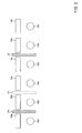
Fig. 1 shows part of a control module surface with different control elements and control dividing surfaces separating different groups of control elements, -
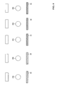
Fig. 2 shows part of a control module surface with control dividing surfaces according to another embodiment, -
Fig. 3 shows part of a control module with control dividing surfaces according to a further embodiment, -
Fig. 4 shows part of a control module with control dividing surfaces according to another embodiment, -
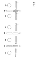
Fig. 5 shows part of a control module surface with control dividing surfaces according to another embodiment, and -
Fig. 6 shows a side view cross section showing the control dividing surface in more detail. -
Fig. 1 shows a section of a control module such as an audio mixing console, the mixing console comprising a plurality of different control elements 10. In the embodiment shown, sixdifferent control elements 10a to 10f are shown. For eachcontrol element 10a to 10f adisplay element 15a to 15f may be provided, the display elements indicating to the operator the function controlled by the respective control element. By way of example, in an equalizer mode, the display element may indicate the adjusted gain for each sub band. It should be understood that the display elements can be provided but they need not necessarily be provided. Between two control elements, acontrol dividing surface 20 may be provided. The control dividing surface can be illuminated by a light source not shown inFig. 1 , e.g. a light emitting diode LED, the control dividing surfaces visually separating one group of control elements from another group of control elements. In the example shown inFig. 1 different groups of control elements are provided. The first group of control elements is presented bycontrol element 10a used for adjusting a first predetermined function or parameter of the mixing console. The second group, in the embodiment shown, consists ofcontrol element element Fig. 1 twocontrol dividing surfaces control element 10a ends at this control dividing surface whereas another group comprising thecontrol elements shaded area control elements control dividing surfaces control element 10c, thecontrol dividing surfaces Fig. 1 , the group comprising thecontrol elements control elements control element 10f. In order to indicate to the operator that there is sub-dividing of one group, e.g. between equalizing bands in an equalizing mode, only thecontrol dividing surface 23b is illuminated whereas thecontrol dividing surface 23a is not illuminated. When the user looks onto the mixing console as shown inFig. 1 it becomes clear that thecontrol elements 10a to 10f are from three different groups and that for one group two different subgroups exist. In this example, the two neighbouringcontrol dividing surfaces control dividing surface 23b separates two subgroups. - In
Fig. 2 another embodiment is shown showing a similar embodiment to the one shown inFig. 1 . The same elements are referenced by the same reference numerals. In this embodiment, the different control elements are separated by a one-piece control dividing surface such as thesurfaces 20 to 22. In the embodiment shown,control elements 10b to 10d build one group and controlelements control element 10a build other groups respectively. In this example, thecontrol dividing surfaces - In
Fig. 3 another mixing console with different control elements 30, 31 and 32 is shown. In this embodiment, the control elements are shown in a matrix form, the first row of control elements being designated as control element 30-1, 30-2, 30-3..., The second row comprising the control element 31-1,31-2, 31-3 etc.. Between the different control elements control dividing surfaces can be provided. In the embodiment shown inFig. 3 , only some of the control dividing surfaces are shown. In this embodiment, the control elements 30-1, 30-2, 31-1and 31-2 build one group of control elements whereas other control elements such as control element 30-3, 30-4, 31-3 and 31-4 and 32-1 to 32-4 build another group. For better delimiting different groups,control dividing surfaces 35 are illuminated whereas other control dividing surfaces such as thesurfaces 36 are not illuminated. Thecontrol dividing surface 37 separating the control element 30-4, 31-4 and 32-4 from the other control elements may be illuminated in the same way as the control dividing surfaces 35. However, it is also possible that thecontrol dividing surfaces 37 are illuminated in another colour than thecontrol dividing surfaces 35 as indicated by the differently hedged areas. - In the embodiment 4, it is shown that the control dividing surfaces can also be used to group the different control elements together using different colours. In the embodiment shown in
Fig. 4 , the control dividing surfaces are not used for separating different control elements from one another but they are used to show which of the control elements belong together using different colours. In the embodiment shown, thecontrol elements control dividing surfaces 45 having the same colour whereas thecontrol dividing surfaces 46 illuminating thedifferent elements - In
Fig. 5 an embodiment is shown combining the embodiment shown inFigs. 1 ,2 with the embodiment shown inFig. 4 .Control elements 50a to 50e are provided in which controlelement 50a belongs to one group whereascontrol elements 50b to 50e belong to another group of control elements. The horizontal control dividing surfaces are illuminated in different colours indicating which group the respective control element belongs to. Thecontrol dividing surface 55 is illuminated in one colour whereas thecontrol dividing surfaces 56 are illuminated in another colour indicating that all these control elements belong to another group. Furthermore, vertical control dividing surfaces are provided underlining the difference between the different groups. Ascontrol element 50a belongs to another group thancontrol element 50b, the verticalcontrol dividing surfaces control dividing surfaces control elements control dividing surfaces 56 comprises two sub-groups, one sub-group containingcontrol elements 50b, c, d and another subgroup containingcontrol element 50e. Ascontrol elements surface 56. Due to the fact that these elements belong to different subgroups, thecontrol dividing surface 59b is illuminated whereas thecontrol dividing surface 59a is not illuminated indicating the division into subgroups. - In
Fig. 6 a schematic partial sectional view of the mixing console is shown. The illuminated surface can be obtained by providinglight pipes 60 with a throughhole 61 at the upper surface of the light pipes, the through hole being provided on thecontrol surface 62 of the mixing console. The light pipes can be illuminated by alight source 64 which can be either situated below thelight pipe 60 or as in the embodiment shown inFig. 6 next to the light pipe. The throughhole 61 can be covered by a light permeable cover such as glass. The different colours used to illuminate the control dividing surface in different colours can be obtained by either using light sources emitting different colours or by a light source and by the use of different filters. The colours may follow the VI6 format. - Summarizing, as explained above, the illumination system is used to "segment" a physical control surface in order to make it clearer to the operator where one type of control ends and another starts. Colour may be used to enhance the effect.
Claims (11)
- A control module comprising:- a plurality of control elements (10, 30, 40, 50), wherein a control element is configured in such a way that different functions of the control module are controlled by one control element, wherein the control elements are grouped into different groups of control elements, each group controlling a predetermined function of the control module,- an illumination system providing illuminated control dividing surfaces (20, 35, 37, 45, 55) which visually separate one group of control elements from another group of control elements, wherein the illumination system illuminates the control dividing surfaces depending on the separation of the control elements into different groups.
- The control module according to claim 1, wherein the illumination system comprises a plurality of different control dividing surfaces which can be illuminated separately.
- The control module according to claim 1 or 2, wherein each control dividing surface (20, 35, 37, 45, 55) is illuminated by a light source (64).
- The control module according to any of the preceding claims, wherein the control dividing surface is an elongated area in a control surface (62) of the control module where the control elements are provided.
- The control module according to any of the preceding claims, wherein the control dividing surface is a light pipe (60) with a through hole (61) in a control surface (62) where the control elements are provided.
- The control module according to any of the preceding claims, wherein said control dividing surface (20) separates one group of control elements from another group of control elements.
- The control module according to any of the preceding claims, wherein the control dividing surfaces are provided in a control surface of the control module in such a way that neighbouring control dividing surfaces (20a, 20b) build a combined control dividing surface.
- The control module according to claim 7, wherein, when one group of control elements is separated into at least two subgroups, the subgroups of said one group are separated by one control dividing surface, whereas two different groups are separated by said combined control dividing surface.
- The control module according to any of the preceding claims, wherein the illumination system illuminates the control dividing surfaces in different colours, the colour indicating to which of the groups the control element belongs to.
- The control module according to any of the preceding claims, wherein the colours follow the Vi6 format.
- The control module according to any of the preceding claims, wherein the control module is an audio mixing console.
Priority Applications (6)
| Application Number | Priority Date | Filing Date | Title |
|---|---|---|---|
| AT08011209T ATE499767T1 (en) | 2008-06-19 | 2008-06-19 | SOUND MIXING CONSOLE |
| DE602008005123T DE602008005123D1 (en) | 2008-06-19 | 2008-06-19 | Tonmischkonsole |
| EP08011209A EP2136493B1 (en) | 2008-06-19 | 2008-06-19 | Audio mixing console |
| PCT/EP2009/004446 WO2009153055A1 (en) | 2008-06-19 | 2009-06-19 | Audio mixing console |
| CN200980123276.6A CN102067489B (en) | 2008-06-19 | 2009-06-19 | Audio mixing console |
| US13/000,321 US8690370B2 (en) | 2008-06-19 | 2009-06-19 | Audio mixing console |
Applications Claiming Priority (1)
| Application Number | Priority Date | Filing Date | Title |
|---|---|---|---|
| EP08011209A EP2136493B1 (en) | 2008-06-19 | 2008-06-19 | Audio mixing console |
Publications (2)
| Publication Number | Publication Date |
|---|---|
| EP2136493A1 true EP2136493A1 (en) | 2009-12-23 |
| EP2136493B1 EP2136493B1 (en) | 2011-02-23 |
Family
ID=40524550
Family Applications (1)
| Application Number | Title | Priority Date | Filing Date |
|---|---|---|---|
| EP08011209A Active EP2136493B1 (en) | 2008-06-19 | 2008-06-19 | Audio mixing console |
Country Status (6)
| Country | Link |
|---|---|
| US (1) | US8690370B2 (en) |
| EP (1) | EP2136493B1 (en) |
| CN (1) | CN102067489B (en) |
| AT (1) | ATE499767T1 (en) |
| DE (1) | DE602008005123D1 (en) |
| WO (1) | WO2009153055A1 (en) |
Families Citing this family (5)
| Publication number | Priority date | Publication date | Assignee | Title |
|---|---|---|---|---|
| EP2637327A1 (en) * | 2012-03-09 | 2013-09-11 | Harman International Industries Ltd. | Audio mixing console with lighting control and method of mixing by means of a mixing console |
| US10191607B2 (en) * | 2013-03-15 | 2019-01-29 | Avid Technology, Inc. | Modular audio control surface |
| CN105229947A (en) | 2013-05-17 | 2016-01-06 | 哈曼国际工业有限公司 | Audio mixer system |
| WO2015052601A1 (en) * | 2013-10-07 | 2015-04-16 | Jurij Beklemisev Individuali Imone | Wireless handheld controller |
| CN109005000B (en) * | 2018-08-09 | 2019-12-20 | 广州市艾涛普电子有限公司 | Detachable tuning device and control method |
Citations (3)
| Publication number | Priority date | Publication date | Assignee | Title |
|---|---|---|---|---|
| US20040066943A1 (en) * | 2002-10-04 | 2004-04-08 | Yamaha Corporation | Mixing console having visual marking system applied to manual operators with subgrouping |
| US20070182864A1 (en) * | 2003-04-04 | 2007-08-09 | Evolution Broadcastpty Limited | Broadcast control |
| US20070274062A1 (en) * | 2003-08-21 | 2007-11-29 | Robert Huber | Slide Controller for an Audio-Mixer |
Family Cites Families (2)
| Publication number | Priority date | Publication date | Assignee | Title |
|---|---|---|---|---|
| DE10014221A1 (en) * | 2000-03-22 | 2001-10-04 | Bosch Gmbh Robert | Electrical equipment with illuminable operating devices, e.g. car radio, navigation system, mobile telephone etc. has illumination state of keys set based on assigned function |
| EP1777609A1 (en) * | 2005-10-11 | 2007-04-25 | Sony Ericsson Mobile Communications AB | Keypad for an electronic equipment and method for operating a keypad for an electronic equipment |
-
2008
- 2008-06-19 EP EP08011209A patent/EP2136493B1/en active Active
- 2008-06-19 AT AT08011209T patent/ATE499767T1/en not_active IP Right Cessation
- 2008-06-19 DE DE602008005123T patent/DE602008005123D1/en active Active
-
2009
- 2009-06-19 WO PCT/EP2009/004446 patent/WO2009153055A1/en not_active Ceased
- 2009-06-19 US US13/000,321 patent/US8690370B2/en active Active
- 2009-06-19 CN CN200980123276.6A patent/CN102067489B/en active Active
Patent Citations (3)
| Publication number | Priority date | Publication date | Assignee | Title |
|---|---|---|---|---|
| US20040066943A1 (en) * | 2002-10-04 | 2004-04-08 | Yamaha Corporation | Mixing console having visual marking system applied to manual operators with subgrouping |
| US20070182864A1 (en) * | 2003-04-04 | 2007-08-09 | Evolution Broadcastpty Limited | Broadcast control |
| US20070274062A1 (en) * | 2003-08-21 | 2007-11-29 | Robert Huber | Slide Controller for an Audio-Mixer |
Also Published As
| Publication number | Publication date |
|---|---|
| ATE499767T1 (en) | 2011-03-15 |
| EP2136493B1 (en) | 2011-02-23 |
| CN102067489B (en) | 2014-06-11 |
| WO2009153055A1 (en) | 2009-12-23 |
| CN102067489A (en) | 2011-05-18 |
| US20110188260A1 (en) | 2011-08-04 |
| US8690370B2 (en) | 2014-04-08 |
| DE602008005123D1 (en) | 2011-04-07 |
Similar Documents
| Publication | Publication Date | Title |
|---|---|---|
| EP2136493B1 (en) | Audio mixing console | |
| CA2255346A1 (en) | Optical multiplexor/demultiplexor | |
| CN101848409B (en) | Audio mixer | |
| NO20010301L (en) | Navigation system for multi-channel digital television system | |
| CA2222031A1 (en) | Tiled, flat-panel displays with color-correction capability | |
| DE60334136D1 (en) | CENTRALIZED HEALTH UNIT FOR THE PROVISION OF VIDEO AND DATA FOR SEVERAL LOCATIONS | |
| ATE291490T1 (en) | LIQUID DISTRIBUTION SYSTEM | |
| CN1841494B (en) | Digital mixer and control method for display of the same | |
| CA2253703A1 (en) | Transmission system for transmitting a flexible multiplex signal | |
| WO2014097660A1 (en) | Wall surface greening and atmosphere purification device and system using same | |
| US7573536B2 (en) | Method for controlling a device for the distribution and processing of video signals | |
| CN102724009A (en) | System for controlling a mixer via external controller | |
| US20160072464A1 (en) | Method of operating an electronic device with a master fader and a plurality of slave faders | |
| US7366313B2 (en) | Mixing console having visual marking system applied to manual operators with subgrouping | |
| WO2004100433A3 (en) | A multi-channel tuner using a discrete cosine transform | |
| FI86221C (en) | Speed indicator for rail vehicles | |
| CN107295379A (en) | A kind of video wall splicing system | |
| CN107504018A (en) | Valve module | |
| US5014341A (en) | Hybrid master control desk for analog and digital audio signals | |
| WO2008037671A1 (en) | Sensor key, electronic input unit and electronic device | |
| GB737136A (en) | Improvements in or relating to multiplex television systems | |
| TW200720996A (en) | Method for controlling colors of on screen display system | |
| US20040018019A1 (en) | Interleaver-based multiplexer and demultiplexer | |
| TW200603019A (en) | Parking area surveillance system and method for parking area surveillance | |
| EP0881830A3 (en) | Video signal player |
Legal Events
| Date | Code | Title | Description |
|---|---|---|---|
| PUAI | Public reference made under article 153(3) epc to a published international application that has entered the european phase |
Free format text: ORIGINAL CODE: 0009012 |
|
| AK | Designated contracting states |
Kind code of ref document: A1 Designated state(s): AT BE BG CH CY CZ DE DK EE ES FI FR GB GR HR HU IE IS IT LI LT LU LV MC MT NL NO PL PT RO SE SI SK TR |
|
| AX | Request for extension of the european patent |
Extension state: AL BA MK RS |
|
| 17P | Request for examination filed |
Effective date: 20100414 |
|
| 17Q | First examination report despatched |
Effective date: 20100615 |
|
| AKX | Designation fees paid |
Designated state(s): AT BE BG CH CY CZ DE DK EE ES FI FR GB GR HR HU IE IS IT LI LT LU LV MC MT NL NO PL PT RO SE SI SK TR |
|
| GRAP | Despatch of communication of intention to grant a patent |
Free format text: ORIGINAL CODE: EPIDOSNIGR1 |
|
| GRAS | Grant fee paid |
Free format text: ORIGINAL CODE: EPIDOSNIGR3 |
|
| GRAA | (expected) grant |
Free format text: ORIGINAL CODE: 0009210 |
|
| AK | Designated contracting states |
Kind code of ref document: B1 Designated state(s): AT BE BG CH CY CZ DE DK EE ES FI FR GB GR HR HU IE IS IT LI LT LU LV MC MT NL NO PL PT RO SE SI SK TR |
|
| REG | Reference to a national code |
Ref country code: GB Ref legal event code: FG4D |
|
| REG | Reference to a national code |
Ref country code: CH Ref legal event code: EP |
|
| REG | Reference to a national code |
Ref country code: IE Ref legal event code: FG4D |
|
| REF | Corresponds to: |
Ref document number: 602008005123 Country of ref document: DE Date of ref document: 20110407 Kind code of ref document: P |
|
| REG | Reference to a national code |
Ref country code: DE Ref legal event code: R096 Ref document number: 602008005123 Country of ref document: DE Effective date: 20110407 |
|
| REG | Reference to a national code |
Ref country code: NL Ref legal event code: VDEP Effective date: 20110223 |
|
| LTIE | Lt: invalidation of european patent or patent extension |
Effective date: 20110223 |
|
| PG25 | Lapsed in a contracting state [announced via postgrant information from national office to epo] |
Ref country code: GR Free format text: LAPSE BECAUSE OF FAILURE TO SUBMIT A TRANSLATION OF THE DESCRIPTION OR TO PAY THE FEE WITHIN THE PRESCRIBED TIME-LIMIT Effective date: 20110524 Ref country code: NO Free format text: LAPSE BECAUSE OF FAILURE TO SUBMIT A TRANSLATION OF THE DESCRIPTION OR TO PAY THE FEE WITHIN THE PRESCRIBED TIME-LIMIT Effective date: 20110523 Ref country code: LV Free format text: LAPSE BECAUSE OF FAILURE TO SUBMIT A TRANSLATION OF THE DESCRIPTION OR TO PAY THE FEE WITHIN THE PRESCRIBED TIME-LIMIT Effective date: 20110223 Ref country code: PT Free format text: LAPSE BECAUSE OF FAILURE TO SUBMIT A TRANSLATION OF THE DESCRIPTION OR TO PAY THE FEE WITHIN THE PRESCRIBED TIME-LIMIT Effective date: 20110623 Ref country code: HR Free format text: LAPSE BECAUSE OF FAILURE TO SUBMIT A TRANSLATION OF THE DESCRIPTION OR TO PAY THE FEE WITHIN THE PRESCRIBED TIME-LIMIT Effective date: 20110223 Ref country code: ES Free format text: LAPSE BECAUSE OF FAILURE TO SUBMIT A TRANSLATION OF THE DESCRIPTION OR TO PAY THE FEE WITHIN THE PRESCRIBED TIME-LIMIT Effective date: 20110603 Ref country code: LT Free format text: LAPSE BECAUSE OF FAILURE TO SUBMIT A TRANSLATION OF THE DESCRIPTION OR TO PAY THE FEE WITHIN THE PRESCRIBED TIME-LIMIT Effective date: 20110223 Ref country code: SE Free format text: LAPSE BECAUSE OF FAILURE TO SUBMIT A TRANSLATION OF THE DESCRIPTION OR TO PAY THE FEE WITHIN THE PRESCRIBED TIME-LIMIT Effective date: 20110223 |
|
| PG25 | Lapsed in a contracting state [announced via postgrant information from national office to epo] |
Ref country code: BE Free format text: LAPSE BECAUSE OF FAILURE TO SUBMIT A TRANSLATION OF THE DESCRIPTION OR TO PAY THE FEE WITHIN THE PRESCRIBED TIME-LIMIT Effective date: 20110223 Ref country code: BG Free format text: LAPSE BECAUSE OF FAILURE TO SUBMIT A TRANSLATION OF THE DESCRIPTION OR TO PAY THE FEE WITHIN THE PRESCRIBED TIME-LIMIT Effective date: 20110523 Ref country code: SI Free format text: LAPSE BECAUSE OF FAILURE TO SUBMIT A TRANSLATION OF THE DESCRIPTION OR TO PAY THE FEE WITHIN THE PRESCRIBED TIME-LIMIT Effective date: 20110223 Ref country code: AT Free format text: LAPSE BECAUSE OF FAILURE TO SUBMIT A TRANSLATION OF THE DESCRIPTION OR TO PAY THE FEE WITHIN THE PRESCRIBED TIME-LIMIT Effective date: 20110223 Ref country code: CY Free format text: LAPSE BECAUSE OF FAILURE TO SUBMIT A TRANSLATION OF THE DESCRIPTION OR TO PAY THE FEE WITHIN THE PRESCRIBED TIME-LIMIT Effective date: 20110223 Ref country code: NL Free format text: LAPSE BECAUSE OF FAILURE TO SUBMIT A TRANSLATION OF THE DESCRIPTION OR TO PAY THE FEE WITHIN THE PRESCRIBED TIME-LIMIT Effective date: 20110223 Ref country code: FI Free format text: LAPSE BECAUSE OF FAILURE TO SUBMIT A TRANSLATION OF THE DESCRIPTION OR TO PAY THE FEE WITHIN THE PRESCRIBED TIME-LIMIT Effective date: 20110223 |
|
| PG25 | Lapsed in a contracting state [announced via postgrant information from national office to epo] |
Ref country code: DK Free format text: LAPSE BECAUSE OF FAILURE TO SUBMIT A TRANSLATION OF THE DESCRIPTION OR TO PAY THE FEE WITHIN THE PRESCRIBED TIME-LIMIT Effective date: 20110223 Ref country code: EE Free format text: LAPSE BECAUSE OF FAILURE TO SUBMIT A TRANSLATION OF THE DESCRIPTION OR TO PAY THE FEE WITHIN THE PRESCRIBED TIME-LIMIT Effective date: 20110223 |
|
| PG25 | Lapsed in a contracting state [announced via postgrant information from national office to epo] |
Ref country code: RO Free format text: LAPSE BECAUSE OF FAILURE TO SUBMIT A TRANSLATION OF THE DESCRIPTION OR TO PAY THE FEE WITHIN THE PRESCRIBED TIME-LIMIT Effective date: 20110223 Ref country code: SK Free format text: LAPSE BECAUSE OF FAILURE TO SUBMIT A TRANSLATION OF THE DESCRIPTION OR TO PAY THE FEE WITHIN THE PRESCRIBED TIME-LIMIT Effective date: 20110223 Ref country code: CZ Free format text: LAPSE BECAUSE OF FAILURE TO SUBMIT A TRANSLATION OF THE DESCRIPTION OR TO PAY THE FEE WITHIN THE PRESCRIBED TIME-LIMIT Effective date: 20110223 |
|
| PG25 | Lapsed in a contracting state [announced via postgrant information from national office to epo] |
Ref country code: MT Free format text: LAPSE BECAUSE OF FAILURE TO SUBMIT A TRANSLATION OF THE DESCRIPTION OR TO PAY THE FEE WITHIN THE PRESCRIBED TIME-LIMIT Effective date: 20110223 |
|
| PLBE | No opposition filed within time limit |
Free format text: ORIGINAL CODE: 0009261 |
|
| STAA | Information on the status of an ep patent application or granted ep patent |
Free format text: STATUS: NO OPPOSITION FILED WITHIN TIME LIMIT |
|
| 26N | No opposition filed |
Effective date: 20111124 |
|
| PG25 | Lapsed in a contracting state [announced via postgrant information from national office to epo] |
Ref country code: PL Free format text: LAPSE BECAUSE OF FAILURE TO SUBMIT A TRANSLATION OF THE DESCRIPTION OR TO PAY THE FEE WITHIN THE PRESCRIBED TIME-LIMIT Effective date: 20110223 |
|
| REG | Reference to a national code |
Ref country code: DE Ref legal event code: R097 Ref document number: 602008005123 Country of ref document: DE Effective date: 20111124 |
|
| REG | Reference to a national code |
Ref country code: IE Ref legal event code: MM4A |
|
| PG25 | Lapsed in a contracting state [announced via postgrant information from national office to epo] |
Ref country code: IE Free format text: LAPSE BECAUSE OF NON-PAYMENT OF DUE FEES Effective date: 20110619 |
|
| PG25 | Lapsed in a contracting state [announced via postgrant information from national office to epo] |
Ref country code: IT Free format text: LAPSE BECAUSE OF FAILURE TO SUBMIT A TRANSLATION OF THE DESCRIPTION OR TO PAY THE FEE WITHIN THE PRESCRIBED TIME-LIMIT Effective date: 20110223 |
|
| PG25 | Lapsed in a contracting state [announced via postgrant information from national office to epo] |
Ref country code: MC Free format text: LAPSE BECAUSE OF NON-PAYMENT OF DUE FEES Effective date: 20110630 |
|
| PG25 | Lapsed in a contracting state [announced via postgrant information from national office to epo] |
Ref country code: LU Free format text: LAPSE BECAUSE OF NON-PAYMENT OF DUE FEES Effective date: 20110619 |
|
| PG25 | Lapsed in a contracting state [announced via postgrant information from national office to epo] |
Ref country code: IS Free format text: LAPSE BECAUSE OF FAILURE TO SUBMIT A TRANSLATION OF THE DESCRIPTION OR TO PAY THE FEE WITHIN THE PRESCRIBED TIME-LIMIT Effective date: 20110223 |
|
| PGFP | Annual fee paid to national office [announced via postgrant information from national office to epo] |
Ref country code: CH Payment date: 20130627 Year of fee payment: 6 |
|
| PGFP | Annual fee paid to national office [announced via postgrant information from national office to epo] |
Ref country code: FR Payment date: 20130702 Year of fee payment: 6 |
|
| PG25 | Lapsed in a contracting state [announced via postgrant information from national office to epo] |
Ref country code: TR Free format text: LAPSE BECAUSE OF FAILURE TO SUBMIT A TRANSLATION OF THE DESCRIPTION OR TO PAY THE FEE WITHIN THE PRESCRIBED TIME-LIMIT Effective date: 20110223 |
|
| PG25 | Lapsed in a contracting state [announced via postgrant information from national office to epo] |
Ref country code: HU Free format text: LAPSE BECAUSE OF FAILURE TO SUBMIT A TRANSLATION OF THE DESCRIPTION OR TO PAY THE FEE WITHIN THE PRESCRIBED TIME-LIMIT Effective date: 20110223 |
|
| REG | Reference to a national code |
Ref country code: CH Ref legal event code: PL |
|
| REG | Reference to a national code |
Ref country code: FR Ref legal event code: ST Effective date: 20150227 |
|
| PG25 | Lapsed in a contracting state [announced via postgrant information from national office to epo] |
Ref country code: CH Free format text: LAPSE BECAUSE OF NON-PAYMENT OF DUE FEES Effective date: 20140630 Ref country code: LI Free format text: LAPSE BECAUSE OF NON-PAYMENT OF DUE FEES Effective date: 20140630 |
|
| PG25 | Lapsed in a contracting state [announced via postgrant information from national office to epo] |
Ref country code: FR Free format text: LAPSE BECAUSE OF NON-PAYMENT OF DUE FEES Effective date: 20140630 |
|
| P01 | Opt-out of the competence of the unified patent court (upc) registered |
Effective date: 20230526 |
|
| PGFP | Annual fee paid to national office [announced via postgrant information from national office to epo] |
Ref country code: DE Payment date: 20250520 Year of fee payment: 18 |
|
| PGFP | Annual fee paid to national office [announced via postgrant information from national office to epo] |
Ref country code: GB Payment date: 20250520 Year of fee payment: 18 |