EP2136466A1 - Medical infusion system with pulse width modulation and safety circuit - Google Patents
Medical infusion system with pulse width modulation and safety circuit Download PDFInfo
- Publication number
- EP2136466A1 EP2136466A1 EP08158667A EP08158667A EP2136466A1 EP 2136466 A1 EP2136466 A1 EP 2136466A1 EP 08158667 A EP08158667 A EP 08158667A EP 08158667 A EP08158667 A EP 08158667A EP 2136466 A1 EP2136466 A1 EP 2136466A1
- Authority
- EP
- European Patent Office
- Prior art keywords
- potential
- circuit
- switching device
- power supply
- safety circuit
- Prior art date
- Legal status (The legal status is an assumption and is not a legal conclusion. Google has not performed a legal analysis and makes no representation as to the accuracy of the status listed.)
- Granted
Links
Images




Classifications
-
- A—HUMAN NECESSITIES
- A61—MEDICAL OR VETERINARY SCIENCE; HYGIENE
- A61M—DEVICES FOR INTRODUCING MEDIA INTO, OR ONTO, THE BODY; DEVICES FOR TRANSDUCING BODY MEDIA OR FOR TAKING MEDIA FROM THE BODY; DEVICES FOR PRODUCING OR ENDING SLEEP OR STUPOR
- A61M5/00—Devices for bringing media into the body in a subcutaneous, intra-vascular or intramuscular way; Accessories therefor, e.g. filling or cleaning devices, arm rests
- A61M5/14—Infusion devices, e.g. infusing by gravity; Blood infusion; Accessories therefor
- A61M5/142—Pressure infusion, e.g. using pumps
-
- H—ELECTRICITY
- H02—GENERATION; CONVERSION OR DISTRIBUTION OF ELECTRIC POWER
- H02P—CONTROL OR REGULATION OF ELECTRIC MOTORS, ELECTRIC GENERATORS OR DYNAMO-ELECTRIC CONVERTERS; CONTROLLING TRANSFORMERS, REACTORS OR CHOKE COILS
- H02P7/00—Arrangements for regulating or controlling the speed or torque of electric DC motors
- H02P7/06—Arrangements for regulating or controlling the speed or torque of electric DC motors for regulating or controlling an individual DC dynamo-electric motor by varying field or armature current
- H02P7/18—Arrangements for regulating or controlling the speed or torque of electric DC motors for regulating or controlling an individual DC dynamo-electric motor by varying field or armature current by master control with auxiliary power
- H02P7/24—Arrangements for regulating or controlling the speed or torque of electric DC motors for regulating or controlling an individual DC dynamo-electric motor by varying field or armature current by master control with auxiliary power using discharge tubes or semiconductor devices
- H02P7/28—Arrangements for regulating or controlling the speed or torque of electric DC motors for regulating or controlling an individual DC dynamo-electric motor by varying field or armature current by master control with auxiliary power using discharge tubes or semiconductor devices using semiconductor devices
- H02P7/285—Arrangements for regulating or controlling the speed or torque of electric DC motors for regulating or controlling an individual DC dynamo-electric motor by varying field or armature current by master control with auxiliary power using discharge tubes or semiconductor devices using semiconductor devices controlling armature supply only
- H02P7/29—Arrangements for regulating or controlling the speed or torque of electric DC motors for regulating or controlling an individual DC dynamo-electric motor by varying field or armature current by master control with auxiliary power using discharge tubes or semiconductor devices using semiconductor devices controlling armature supply only using pulse modulation
-
- A—HUMAN NECESSITIES
- A61—MEDICAL OR VETERINARY SCIENCE; HYGIENE
- A61M—DEVICES FOR INTRODUCING MEDIA INTO, OR ONTO, THE BODY; DEVICES FOR TRANSDUCING BODY MEDIA OR FOR TAKING MEDIA FROM THE BODY; DEVICES FOR PRODUCING OR ENDING SLEEP OR STUPOR
- A61M5/00—Devices for bringing media into the body in a subcutaneous, intra-vascular or intramuscular way; Accessories therefor, e.g. filling or cleaning devices, arm rests
- A61M5/14—Infusion devices, e.g. infusing by gravity; Blood infusion; Accessories therefor
- A61M5/142—Pressure infusion, e.g. using pumps
- A61M2005/14208—Pressure infusion, e.g. using pumps with a programmable infusion control system, characterised by the infusion program
-
- A—HUMAN NECESSITIES
- A61—MEDICAL OR VETERINARY SCIENCE; HYGIENE
- A61M—DEVICES FOR INTRODUCING MEDIA INTO, OR ONTO, THE BODY; DEVICES FOR TRANSDUCING BODY MEDIA OR FOR TAKING MEDIA FROM THE BODY; DEVICES FOR PRODUCING OR ENDING SLEEP OR STUPOR
- A61M5/00—Devices for bringing media into the body in a subcutaneous, intra-vascular or intramuscular way; Accessories therefor, e.g. filling or cleaning devices, arm rests
- A61M5/14—Infusion devices, e.g. infusing by gravity; Blood infusion; Accessories therefor
- A61M5/168—Means for controlling media flow to the body or for metering media to the body, e.g. drip meters, counters
- A61M5/172—Means for controlling media flow to the body or for metering media to the body, e.g. drip meters, counters electrical or electronic
Definitions
- the present invention relates to a medical infusion system comprising a control signal generator, a safety circuit, a switching device and a pump motor.
- the invention further relates to a method for driving a pump motor in a medical infusion system.
- United States Patent Application US 2002/0071225 A1 discloses several solutions for this problem.
- the first solution is using a motor that needs a multiple of the voltage provided by the battery. In case a short circuit directly connects the motor to the battery, the voltage is not sufficient to drive the motor.
- a second solution uses a safety circuit that closes the power supply circuit of the pump motor only when a special AC signal is applied to the safety circuit.
- the drawback of the first solution is that an expensive and complex DC-DC step-up converter is needed.
- the drawback of the second solution is that a second dedicated circuit is needed next to control electronics that control the rated supply voltage and therefore the motor in order to regulate the amount of substance or drug to be infused.
- the problem to be solved by the present invention is to provide an improved and simple device and method for controlled and safe infusion of a substance or drug.
- a medical infusion system comprises a control signal generator, a safety circuit, a switching device and a pump motor, wherein the pump motor and the switching device are connected in series and constitute a power supply circuit to be connected to a power supply, the output of the control signal generator is connected to the input of the safety circuit and the output of the safety circuit is connected to a control input of the switching device.
- the voltage of the power supply is termed VCC.
- the pump motor preferably is a DC motor,
- the pump motor is part of a pump that delivers a substance or drug or the pump motor drives a piston inside a container holding the substance or drug.
- the control signal generator is configured to generate a control signal with two potentials, an "on” potential and an “off” potential, wherein an "on” potential is any potential that, if this potential is present at a control input of the switching device, makes the switching device close the power supply circuit, and an “off” potential is any potential that makes the switching device open, that means interrupt, the power supply circuit.
- the "on” potential can be a constant (positive) voltage, that is logical "high”, or ground, that is logical "low”.
- the safety circuit is configured to apply an "off' potential to its output if there is an “off” potential at its input; to apply an “on” potential to its output if there continuously is an “on” potential at its input for a duration up to a predetermined amount of time; and to apply an "off” potential to its output if there continuously is an “on” potential at its input for a duration longer than a predetermined amount of time.
- the safety circuit receives the control signal from the control signal generator, wherein the control signal has the potentials as described above.
- the switching device switches the power supply circuit of the pump motor according to the signal applied to the control input of the switching device. This causes operation of the motor and thus infusion of a substance or drug controlled by the control signal
- the motor control is very exact, resulting in a highly accurate delivery rate.
- surge currents are reduced which increases battery life.
- the safety circuit applies an "off” potential to its output if there is an “off' potential at its input; applies an “on” potential to its output if' there continuously is an “on” potential at its input for a duration up to a predetermined amount of time; and applies an “off” potential to its output if there continuously is an “on” potential at its input for a duration longer than a predetermined amount of time.
- the safety circuit applies a potential to its output that is equivalent to the potential it has at its input.
- An exception to this is when the signal at its input has "on” potential for a duration longer than a predetermined amount of time. This is a situation that could mean an overdose to the patient.
- the safety circuit applies an "off" potential to its output even though it has an "on” potential at its input.
- a signal to interrupt the power supply circuit is devised from the control signal, which controls the motor and for this reason the delivery rate, itself.
- the signal at the output of the safety circuit might be (slightly) delayed compared to the signal at the input of the safety circuit. This does not affect the function of the medical infusion system, especially if the control signal has a high frequency.
- control signal generator is a PWM (pulse width modulation) generator configured to generate a PWM signal.
- the received control signal then is a PWM signal.
- a PWM signal is a square wave signal with a fixed frequency. Within one cycle, the amplitude of the PWM signal changes twice, first from high to low and then from low to high or via versa.
- the high amplitude usually is any positive DC voltage, for example 3V or 5V, while the low amplitude usually is zero or ground.
- the duty cycle of a PWM signal denotes the fraction of time the signal is high during a cycle.
- the medical infusion system and method described so far fulfil two tasks.
- the first task is to modulatedly switch the power supply circuit on and off according to the control signal, thus allowing to control the amount of substance or drug to be infused to the user.
- the second task is to interrupt the power supply circuit, which means turning off the motor, if the motor was operating continuously for a predetermined amount of time. This means that the amount of substance or drug to be infused to the user at a time can be limited to a none live -threatening dose.
- the predetermined amount of time is much longer than the cycle of the PWM signal, for example more than 40 times the PWM cycle. This means that the safety circuit does not engage, that is interrupts the power supply circuit, before a PWM cycle is over.
- the safety circuit, the switching device and the pump motor constitute a unit that is impervious to fluid, for example by a liquid-tight sealing. This means that fluids, especially the substance or drug to be infused, can't penetrate into the unit to cause failures like e.g. a short circuit.
- the safety circuit eliminates the effect of a short circuit that occurs between the control signal generator and the switching device, and a short circuit can't occur within the liquid-tight sealing, the best possible protection of the user against malfunctions of the medical infusion system is provided.
- the safety circuit comprises an RC circuit.
- one pin of the capacitor of the RC circuit is directly connected to the input of the safety circuit, the other pin of the capacitor is directly connected to the output of the safety circuit, one pin of the resistor of the RC circuit is directly connected to the output of the safety circuit and the other pin of the resistor is connected to a constant potential being equal to the "off" potential.
- the capacitor of the RC circuit While the signal received by the safety circuit, the input signal, has “on” potential, the capacitor of the RC circuit is charged via the resistor of the RC circuit. The potential at the pin of the capacitor that is connected to the resistor is applied to the control input of the switching device. This potential changes towards the "off” potential with a rate following an exponential function determined by the time constant R * C. If this potential has reached a certain level, the switching device will interrupt the power supply circuit. This level, the switching threshold (termed VST), depends on the switching device and possibly on VCC.
- the safety circuit comprises a diode in parallel to the resistor of the RC circuit so that the capacitor of the RC circuit is discharged via the diode if the signal at the input of the safety circuit has "off" potential, that is if the received signal causes the switching device to interrupt the power supply circuit.
- This enables rapid discharging of the capacitor which is necessary to reset the safety circuit so that the switching device can close the power supply circuit the next time an "on" potential is applied to the input of the safety circuit. Otherwise the capacitor would be discharged only via the resistor, which would be too slow due to the time constant of the RC circuit. If the capacitor wasn't sufficiently discharged when the input signal changes from "off' to "on” potential, the remaining voltage over the capacitor would prevent the switching device from closing the power supply circuit.
- the switching device can be of any kind, for example an electro-mechanical switch like a relay or a transistor, like an FET or MOSFET.
- the only limitation is that the switching device must be fast enough to follow the control signal.
- the switching device is a PMOSFET (a p-channel MOSFET), the "on” potential is ground and the “off” potential is a constant positive potential (VPOS).
- VPOS constant positive potential
- the PMOSFET conducts if the potential at its gate is below VST, which is low. That means that the PMOSFET closes the power supply circuit if the control signal applied to the safety circuit is low.
- the capacitor is charged via the resistor and the potential at its pin that is connected to the output of the safety circuit rises towards VPOS.
- the PMOSFET opens, which means interrupts, the power supply circuit when charging of the capacitor has reached a certain level, which is the switching threshold VST of the switching device.
- the switching device is an NMOSFET (an n-channel MOSFET), the "on” potential is a constant positive potential (VPOS) and the “off” potential is ground.
- NMOSFET an n-channel MOSFET
- the NMOSFET conducts if the potential at its gate pin is higher than VST, that is high.
- the capacitor is charged via the resistor and the potential at its pin that is connected to the output of the safety circuit falls towards ground.
- the NMOSFET opens, which means interrupts, the power supply circuit when charging of the capacitor has reached a certain level that is the switching threshold VST of the NMOSFET.
- the control signal has to be the inverse of the control signal of the previous example.
- the constant positive potential VPOS equals the voltage VCC of the power supply. This means that only one voltage is present in the medical infusion system and, in the example using the PMOSFET or any other switching device that opens (interrupts) its output while the signal at its input exceeds a positive switching threshold, the resistor of the RC circuit can be connected to the positive pole of the power supply.
- the safety circuit of the medical infusion system prevents the pump motor from being supplied with current if the duty cycle of the PWM signal at the input of the safety circuit is outside of special boundaries, for example smaller than 2% or larger than 98%.
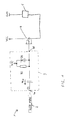
- FIG. 1 shows a medical infusion system I with a PWM generator 2, a safety circuit 3, a NMOSFET 4 as a switching device and a DC pump motor 5.
- the output of the PWM generator 2 is connected to an input 3a of the safety circuit 3, the output 3b of the safety circuit 3 is connected to the gate of the PMOSFET 4, which is the control input of the switching device.
- the motor 5 is connected to a power supply (not shown) with a ground pole (GND) and a positive pole having a voltage VCC versus ground.
- the PMOSFET 4 for example an IRF5851, is included in the power supply circuit between the pump motor 5 and the positive pole of the power supply with its source and drain pins.
- the safety circuit 3 comprises an RC circuit with the capacitor C1 and the resistor R1.
- One pin of the capacitor C1 is directly connected to the input 3a, the other pin of the capacitor C1 is directly connected to the output 3b of the safety circuit 3.
- One pin of the resistor R1 is directly connected to the output 3b, the other pin of the resistor R1 is directly connected to the positive pole of the power supply.
- a diode D1 for example a PMEG2005AEA, with its cathode pointing towards the positive pole of the power supply.
- the PWM generator 2 generates a PWM signal with the two amplitudes 0 (ground, GND, logical low) and VCC (logical high).
- the PWM signal returns back from low ("on” potential) to high ("off” potential) before UC1 has reached the switching threshold VST of PMOSFET 4, that means a value that causes PMOSFET 4 to open the power supply circuit.
- the signal at input 3a gets high, which means VCC
- the potential at output 3b tends to change to VCC + UC1, which causes PMOSFET 4 to open the power supply circuit. Since the potential at output 3b is larger than VCC, capacitor C1 is discharged via resistor R1.
- the safety circuit 3 the PMOSFET 4 and the pump motor 5 are encapsulated to a liquid-tight unit
- This unit has only three electric ports, two for connecting the unit to a power supply and one for connecting the unit to the PWM generator 2.
- the PWM generator 2 too, can be included in the liquid-tight unit.
- the unit then has just the two electric ports to be connected to the power supply.
- the whole electronic too, can be included in the liquid-tight unit.
- the minimal PWM frequency is mainly determined by the motor characteristics.
- the time T can be defined considering the following dimensioning rules: (A) the RC circuit has to fulfil its functionality, (B) the time T has to be as small as possible to prevent undesired infusion and needs to be small enough to prevent an excessive delivery of insulin.
- VST is VCC-Vthreshold.
- Vthreshold is mainly defined by the PMOSFET electrical characteristics and in this example supposed to be much smaller than VCC. Typical values for Vthreshold are: 0.3 V to 0.7 V, typical values for VCC are 3V to 5V.
- the functionality of the safety circuit is to allow a PWM signal to flow through the motor, and hence is to transmit the signal generated by the signal generator 2 basically unchanged from the points 3a to 3b if the signal is correct and to block the signal if it is not correct (in state "on" for a time longer than T).
- the PWM signal is transferred unchanged from 3a to 3b if the safety circuit does not block the PWM signal.
- the PWM "on" state time has to be shorter than 2 ⁇ RC.
- ⁇ RC is chosen such that 1/ ⁇ RC ⁇ PWM frequency.
- the PWM signal will be changed by the safety circuit as in Figure 7 .
- the duty cycle is 80%.
- the PWM duty cycle at the output 3b of the safety circuit 3 may get smaller than the duty cycle at the output 3a of the safety circuit 3, which leads to change of the PWM signal through the safety circuit 3.
- a little more potential remains in the capacitor C1 if discharging is not fast enough. This remaining potential may sum up over several PWM cycles so that VST is erroneously reached, thus blocking the PWM signal.
- the safety circuit 3 transforms the PWM signal at its input 3a, shown in the lower graph of Figure 7 , into a different PWM signal at its output 3b, shown in the upper graph of Figure 7 .
- the maximal duty cycle that can be applied to the input 3a of the safety circuit 3 without modifying and in worst case permanently blocking the PWM signal by the safety circuit 3 is limited.
- the components R1, D1 and C 1 are preferably chosen such that the maximal duty cycle is larger than 90% and particularly larger than 98%.
- the discharge of the capacitor over the diode D1 can be characterised by a ⁇ D1(effective). So a condition for the safety circuit is ⁇ D1(effective) ⁇ ⁇ RC.
- a limitation for the PWM "off" time is that PWM "off" time > 5 / ⁇ D1(effective).
- the second design rule implies that the time T is as short as possible. To ensure the safety circuit functionality, the time T should be not smaller than 5 ⁇ RC. The time T is also designed to prevent an excessive delivery of insulin.
- the maximal time T is a function of the delivery flow speed and is much bigger than 5 ⁇ RC. It can be defined by the insulin overdose delivered to the patient before the motor is stopped. The insulin overdoses must not have health consequences for the patient. T would preferably be defined such that the insulin overdose during the time T is smaller than 10% to 20% of the daily insulin dose.
- FIG 2 shows a complementary embodiment of the one shown in Figure 1 .
- the switching device of the medical infusion system 11 is placed in the power supply circuit between the pump motor 5 and the ground pole (GND) of the power supply (not shown) with its source and drain pins.
- the switching device is an NMOSFET (n-channel MOSFET) 14, for example an IRF5851.
- the gate of the NMOSFET 14 is connected to an output 13b of a safety circuit 13.
- An input 13a of the safety circuit 13 is connected to the output of a PWM generator 12.
- the NMOSFET 14 closes the power supply circuit if it has a high signal at its gate.
- the safety circuit 13 comprises a capacitor C11, a resistor R11 and a diode D11.
- One pin of the capacitor C11 is directly connected to input 13a, the other pin of the capacitor is directly connected to output 13b.
- One pin of resistor R1 1 is directly connected to output 13b, which means that it is directly connected to one pin of capacitor C11, the other pin of the resistor R11 is directly connected to ground potential.
- the diode D11 is placed in parallel to the resistor R11 with its cathode pointing towards output 13b.
- ground or logical low
- VCC or logical high
- the amplitude of the PWM signal at input 13a changes to high, for example the voltage VCC of the power supply
- the potential at output 13b changes to high and the NMOSFET 14 closes the power supply circuit.
- charging of capacitor C11 starts via resistor R11 with a rate depending on the time constant R11 * C11.
- the voltage UC11 falls following an exponential function with an asymptotical value of -VCC.
- the potential at output 13b falls following an exponential function from VCC to 0, If the signal at input 13a is high for longer than a certain amount of time depending on the values of the capacitor C11 and the resistor R11, the potential at output 13b falls below the switching threshold VST of NMOSFET 14, that is to a level that makes NMOSFET 14 interrupt the power supply circuit.
- VST equals Vthreshold of the NMOSFET 14.
- NMOSFET 14 opens the power supply circuit.
- the capacitor C11 is discharged via resistor R11 and in addition via diode D11 while the absolute value of UC1 exceeds the forward voltage of diode D11 After discharging, voltage UC1 and therefore the potential at output 13b is zero and NMOSFET 14 still interrupts the power supply circuit.
- the safety circuit 13 the NMOSFET 14 and the pump motor 5 are encapsulated to a liquid-tight unit.
- This unit has only three electric ports, two for connecting the unit to a power supply and one for connecting the unit to the PWM generator 2.
- the PWM generator 2 too, can be included in the liquid-tight unit.
- the unit then has just the two electric ports to be connected to the power supply.
- the whole electronic, too can be included in the liquid-tight unit.
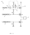
- FIG. 3 shows a medical infusion system 21 with a PWM generator 2, a safety circuit 3, a PMOSFET 4 and a pump motor 5 that is basically identical to the medical infusion system 1 shown in Figure 1 ,
- PMOSFET T2 in the power supply circuit between pump motor 5 and PMOSFET 4 and an NMOSFET T3 between the pump motor 5 and the ground pole of the power supply (not shown).
- the gate of PMOSFET T2 is directly connected to a signal generator 6 and to VCC via the pull-up resistor R2,
- the gate of NMOSFET T3 is directly connected to a signal generator 7 and to ground via pull-down resistor R3
- medical infusion system 21 is basically identical to that of medical infusion system 1 according to Figure 1 .
- PMOSFET T2 and NMOSFET T3 are additional switches to interrupt the power supply circuit.
- PMOSFET T2 interrupts the power supply circuit. If signal generator 6 delivers a low signal, PMOSFET T2 closes the power supply circuit. If signal generator 6 does not deliver any defined signal, for example, if the connection is interrupted, the potential at the gate of PMOSFET T2 is high via resistor R2 and the power supply circuit is interrupted.
- NMOSFET T3 The functionality of signal generator 7, resistor R3 and NMOSFET T3 is basically the same as of signal generator 6, resistor R2 and PMOSFET T2 with the difference that NMOSFET closes the power supply circuit if signal generator 7 delivers a high signal. NMOSFET T3 interrupts the power supply circuit if signal generator 7 delivers a low signal or no defined signal. In the latter case, resistor R3 pulls the potential at the gate of NMOSFET T3 down to ground potential.
- the safety circuit 3 the PMOSFETs 4 and T2, the NMOSFET T3 and the pump motor 5 are encapsulated to a liquid-tight unit.
- This unit has only five electric ports, two for connecting the unit to a power supply and three for connecting the unit to the PWM generator 2 and the signal generators 6 and 7.
- the PWM generator 2, too can be included in the liquid-tight unit.
- the signal generators 6 and 7, too can be included in the liquid-tight unit.
- the whole electronic, too can be included in the liquid-tight unit.
- FIG 4 shows a medical infusion system 31 combining the medical infusion systems 21 shown in Figure 3 and 11 shown in Figure 2 .
- the NMOSFET 14 is placed in the power supply circuit between the NMOSFET T3 and the ground pole of the power supply (not shown). There is only current flowing through pump motor 5 if all four switches 4, 14, T2 and T3 are in conducting state. This is only the case if PWM generator 12 delivers a PWM signal that is the inverse of the PWM signal delivered by PWM generator 2, signal generator 6 delivers a low signal and signal generator 7 delivers a high signal.
- the safety circuits 3 and 13, the PMOSFETs 4 and T2, the NMOSFETs 14 and T3 and the pump motor 5 are encapsulated to a liquid-tight unit.
- This unit has only six electric ports, two for connecting the unit to a power supply and four for connecting the unit to the PWM generators 2 and 12 and the signal generators 6 and 7.
- the PWM generators 2 and 12, too, can be included in the liquid-tight unit.
- the whole electronic, too can be included in the liquid-tight unit.
Landscapes
- Health & Medical Sciences (AREA)
- Engineering & Computer Science (AREA)
- Animal Behavior & Ethology (AREA)
- General Health & Medical Sciences (AREA)
- Biomedical Technology (AREA)
- Heart & Thoracic Surgery (AREA)
- Hematology (AREA)
- Life Sciences & Earth Sciences (AREA)
- Vascular Medicine (AREA)
- Anesthesiology (AREA)
- Public Health (AREA)
- Veterinary Medicine (AREA)
- Power Engineering (AREA)
- Infusion, Injection, And Reservoir Apparatuses (AREA)
- Control Of Electric Motors In General (AREA)
- Control Of Direct Current Motors (AREA)
Abstract
Description
- The present invention relates to a medical infusion system comprising a control signal generator, a safety circuit, a switching device and a pump motor. The invention further relates to a method for driving a pump motor in a medical infusion system.
- Conventional medical infusion systems utilize a variety of motor technologies for driving the infusion pump such as direct current motors, stepper motors, or solenoid motors. When using such a motor in an infusion pump, safety measures must be designed to protect the user from malfunction of the motor, especially to avoid delivering an excessive amount of a substance or drug, for example insulin, to be infused to the user. This might especially occur in case of a short circuit that bypasses the control system of the motor.
- United States Patent Application
US 2002/0071225 A1 discloses several solutions for this problem. The first solution is using a motor that needs a multiple of the voltage provided by the battery. In case a short circuit directly connects the motor to the battery, the voltage is not sufficient to drive the motor. A second solution uses a safety circuit that closes the power supply circuit of the pump motor only when a special AC signal is applied to the safety circuit. - The drawback of the first solution is that an expensive and complex DC-DC step-up converter is needed. The drawback of the second solution is that a second dedicated circuit is needed next to control electronics that control the rated supply voltage and therefore the motor in order to regulate the amount of substance or drug to be infused.
- Thus, the problem to be solved by the present invention is to provide an improved and simple device and method for controlled and safe infusion of a substance or drug.
- This problem is solved by a medical infusion system according to
claim 1 and a method for driving a pump motor and a medical infusion system according toclaim 13. - A medical infusion system according to the present invention comprises a control signal generator, a safety circuit, a switching device and a pump motor, wherein the pump motor and the switching device are connected in series and constitute a power supply circuit to be connected to a power supply, the output of the control signal generator is connected to the input of the safety circuit and the output of the safety circuit is connected to a control input of the switching device. The voltage of the power supply is termed VCC.
- The pump motor preferably is a DC motor, The pump motor is part of a pump that delivers a substance or drug or the pump motor drives a piston inside a container holding the substance or drug.
- The control signal generator is configured to generate a control signal with two potentials, an "on" potential and an "off" potential, wherein an "on" potential is any potential that, if this potential is present at a control input of the switching device, makes the switching device close the power supply circuit, and an "off" potential is any potential that makes the switching device open, that means interrupt, the power supply circuit. Depending on the actual switching device used, the "on" potential can be a constant (positive) voltage, that is logical "high", or ground, that is logical "low".
- The safety circuit is configured to apply an "off' potential to its output if there is an "off" potential at its input; to apply an "on" potential to its output if there continuously is an "on" potential at its input for a duration up to a predetermined amount of time; and to apply an "off" potential to its output if there continuously is an "on" potential at its input for a duration longer than a predetermined amount of time.
- In operation, the safety circuit receives the control signal from the control signal generator, wherein the control signal has the potentials as described above. The switching device switches the power supply circuit of the pump motor according to the signal applied to the control input of the switching device. This causes operation of the motor and thus infusion of a substance or drug controlled by the control signal The motor control is very exact, resulting in a highly accurate delivery rate. In addition, surge currents are reduced which increases battery life.
- The safety circuit applies an "off" potential to its output if there is an "off' potential at its input; applies an "on" potential to its output if' there continuously is an "on" potential at its input for a duration up to a predetermined amount of time; and applies an "off" potential to its output if there continuously is an "on" potential at its input for a duration longer than a predetermined amount of time.
- This means that the safety circuit applies a potential to its output that is equivalent to the potential it has at its input. An exception to this is when the signal at its input has "on" potential for a duration longer than a predetermined amount of time. This is a situation that could mean an overdose to the patient. In this case, the safety circuit applies an "off" potential to its output even though it has an "on" potential at its input. Thus, a signal to interrupt the power supply circuit is devised from the control signal, which controls the motor and for this reason the delivery rate, itself.
- Depending on the structure of the safety circuit, the signal at the output of the safety circuit might be (slightly) delayed compared to the signal at the input of the safety circuit. This does not affect the function of the medical infusion system, especially if the control signal has a high frequency.
- In a preferred embodiment, the control signal generator is a PWM (pulse width modulation) generator configured to generate a PWM signal. The received control signal then is a PWM signal. A PWM signal is a square wave signal with a fixed frequency. Within one cycle, the amplitude of the PWM signal changes twice, first from high to low and then from low to high or via versa.
- The high amplitude usually is any positive DC voltage, for example 3V or 5V, while the low amplitude usually is zero or ground. The duty cycle of a PWM signal denotes the fraction of time the signal is high during a cycle.
- The medical infusion system and method described so far fulfil two tasks. The first task is to modulatedly switch the power supply circuit on and off according to the control signal, thus allowing to control the amount of substance or drug to be infused to the user. The second task is to interrupt the power supply circuit, which means turning off the motor, if the motor was operating continuously for a predetermined amount of time. This means that the amount of substance or drug to be infused to the user at a time can be limited to a none live -threatening dose. In a preferred embodiment, the predetermined amount of time is much longer than the cycle of the PWM signal, for example more than 40 times the PWM cycle. This means that the safety circuit does not engage, that is interrupts the power supply circuit, before a PWM cycle is over.
- In a further preferred embodiment of the present invention, the safety circuit, the switching device and the pump motor constitute a unit that is impervious to fluid, for example by a liquid-tight sealing. This means that fluids, especially the substance or drug to be infused, can't penetrate into the unit to cause failures like e.g. a short circuit.
- Since the safety circuit eliminates the effect of a short circuit that occurs between the control signal generator and the switching device, and a short circuit can't occur within the liquid-tight sealing, the best possible protection of the user against malfunctions of the medical infusion system is provided.
- According to a special embodiment of the invention, the safety circuit comprises an RC circuit. Preferably, one pin of the capacitor of the RC circuit is directly connected to the input of the safety circuit, the other pin of the capacitor is directly connected to the output of the safety circuit, one pin of the resistor of the RC circuit is directly connected to the output of the safety circuit and the other pin of the resistor is connected to a constant potential being equal to the "off" potential.
- While the signal received by the safety circuit, the input signal, has "on" potential, the capacitor of the RC circuit is charged via the resistor of the RC circuit. The potential at the pin of the capacitor that is connected to the resistor is applied to the control input of the switching device. This potential changes towards the "off" potential with a rate following an exponential function determined by the time constant R * C. If this potential has reached a certain level, the switching device will interrupt the power supply circuit. This level, the switching threshold (termed VST), depends on the switching device and possibly on VCC.
- As a preferred option, the safety circuit comprises a diode in parallel to the resistor of the RC circuit so that the capacitor of the RC circuit is discharged via the diode if the signal at the input of the safety circuit has "off" potential, that is if the received signal causes the switching device to interrupt the power supply circuit. This enables rapid discharging of the capacitor which is necessary to reset the safety circuit so that the switching device can close the power supply circuit the next time an "on" potential is applied to the input of the safety circuit. Otherwise the capacitor would be discharged only via the resistor, which would be too slow due to the time constant of the RC circuit. If the capacitor wasn't sufficiently discharged when the input signal changes from "off' to "on" potential, the remaining voltage over the capacitor would prevent the switching device from closing the power supply circuit.
- The switching device can be of any kind, for example an electro-mechanical switch like a relay or a transistor, like an FET or MOSFET. The only limitation is that the switching device must be fast enough to follow the control signal.
- In one example, the switching device is a PMOSFET (a p-channel MOSFET), the "on" potential is ground and the "off" potential is a constant positive potential (VPOS). This constellation is used if the switching device is placed between the pump motor and the positive pole of the power supply. In this example, the PMOSFET conducts if the potential at its gate is below VST, which is low. That means that the PMOSFET closes the power supply circuit if the control signal applied to the safety circuit is low. In this case, the capacitor is charged via the resistor and the potential at its pin that is connected to the output of the safety circuit rises towards VPOS. The PMOSFET opens, which means interrupts, the power supply circuit when charging of the capacitor has reached a certain level, which is the switching threshold VST of the switching device.
- In another example, the switching device is an NMOSFET (an n-channel MOSFET), the "on" potential is a constant positive potential (VPOS) and the "off" potential is ground. This embodiment is complementary to the previous example and is useful if the switching device is located between the motor and the negative pole of the power supply or ground. In this example, the NMOSFET conducts if the potential at its gate pin is higher than VST, that is high. In this case, the capacitor is charged via the resistor and the potential at its pin that is connected to the output of the safety circuit falls towards ground. The NMOSFET opens, which means interrupts, the power supply circuit when charging of the capacitor has reached a certain level that is the switching threshold VST of the NMOSFET. To achieve the same amount of substance or drug to be infused, the control signal has to be the inverse of the control signal of the previous example.
- In a preferred embodiment, the constant positive potential VPOS equals the voltage VCC of the power supply. This means that only one voltage is present in the medical infusion system and, in the example using the PMOSFET or any other switching device that opens (interrupts) its output while the signal at its input exceeds a positive switching threshold, the resistor of the RC circuit can be connected to the positive pole of the power supply.
- The safety circuit of the medical infusion system according to the present invention prevents the pump motor from being supplied with current if the duty cycle of the PWM signal at the input of the safety circuit is outside of special boundaries, for example smaller than 2% or larger than 98%.
- It is apparent to the person skilled in the art that additional switching devices can be provided in the power supply circuit to stop the motor if certain conditions are met.
- A detailed description of embodiments of the invention will be made with reference to the accompanying drawings, wherein like numerals designate corresponding parts in a several figures. Combinations of single features of the several exemplary embodiments are possible.
- Figure 1
- shows a first embodiment of a medical infusion system.
- Figure 2
- shows a second embodiment of a medical infusion system.
- Figure 3
- shows the example of
Figure 1 with two additional switches. - Figure 4
- shows another medical infusion system combining the embodiments according to
Figures 2 and3 . - Figure 5
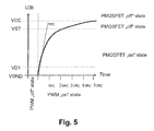
- shows the potential at the output of the safety circuit over time.
- Figure 6
- shows the potential over the capacitor of the safety circuit over time.
- Figure 7
- shows the potential over the capacitor of the safety circuit over time in case of a malfunction.
- In the following examples, all potentials are given with relation to ground. Potentials are also described by their logical counterparts, where zero or ground is logical low and a positive voltage larger than a threshold, for example the switching threshold of a switching device, is logical high. Directly connected means that there is no other component, like for example a diode or a capacitor, between the elements, except for a conductor. This means that nothing but a conductor is between a pin of the first element and a pin of the second element
-
Figure 1 shows a medical infusion system I with aPWM generator 2, asafety circuit 3, aNMOSFET 4 as a switching device and a DC pump motor 5. The output of thePWM generator 2 is connected to aninput 3a of thesafety circuit 3, theoutput 3b of thesafety circuit 3 is connected to the gate of thePMOSFET 4, which is the control input of the switching device. The motor 5 is connected to a power supply (not shown) with a ground pole (GND) and a positive pole having a voltage VCC versus ground. ThePMOSFET 4, for example an IRF5851, is included in the power supply circuit between the pump motor 5 and the positive pole of the power supply with its source and drain pins. - The
safety circuit 3 comprises an RC circuit with the capacitor C1 and the resistor R1. One pin of the capacitor C1 is directly connected to theinput 3a, the other pin of the capacitor C1 is directly connected to theoutput 3b of thesafety circuit 3. One pin of the resistor R1 is directly connected to theoutput 3b, the other pin of the resistor R1 is directly connected to the positive pole of the power supply. In parallel to the resistor R1 is a diode D1, for example a PMEG2005AEA, with its cathode pointing towards the positive pole of the power supply. - Operation of the
medical infusion system 1 is described starting with an uncharged capacitor C1. ThePWM generator 2 generates a PWM signal with the two amplitudes 0 (ground, GND, logical low) and VCC (logical high). - If the PWM signal at the
input 3a changes to high, the potential atoutput 3b changes to high (that means VCC), too, because capacitor C1 is uncharged. Due to the potentials in thesafety circuit 3, the capacitor C1 is not being charged. The high potential of theoutput 3b is applied to the gate ofPMOSFET 4 that therefore opens the power supply circuit and there is no current through the pump motor 5. This means that, in this embodiment, VCC (or logical high) corresponds to the "off" potential, while ground (or logical low) is the "on" potential. - If the PWM signal at the
input 3a changes from high to low, the potential at theoutput 3b also changes to low due to the still uncharged capacitor C1. Therefore thePMOSFET 4 closes the power supply circuit and current flows through the pump motor 5. Due to the potential difference between VCC at the resistor R1 and ground atinput 3a, a current flows through resistor R1 that charges capacitor C1. The voltage UC1 over the capacitor C1 (voltage from 3a to 3b) increases following an exponential rise determined by the time constant τ = R1 * C1, seeFigure 5 , - If there is no malfunction, the PWM signal returns back from low ("on" potential) to high ("off" potential) before UC1 has reached the switching threshold VST of
PMOSFET 4, that means a value that causesPMOSFET 4 to open the power supply circuit. If the signal atinput 3a gets high, which means VCC, the potential atoutput 3b tends to change to VCC + UC1, which causesPMOSFET 4 to open the power supply circuit. Since the potential atoutput 3b is larger than VCC, capacitor C1 is discharged via resistor R1. As long as UC1 is larger than the forward voltage VD1 of diode D1, the diode D1 is in conducting state and rapidly discharges capacitor C1 to UC1 = 0 in addition to resistor R1. - If the PWM signal at
input 3a does not return to high, the capacitor C1 keeps charging asymptotically to UC1 = VCC. If UC1, and thus the potential atoutput 3b, has reached the switching threshold VST ofPMOSFET 4, thePMOSFET 4 opens the power supply circuit and interrupts the flow of current through pump motor 5. When the PWM signal atinput 3a returns to high, the capacitor C1 is discharged via resistor R1 and, depending on UC1, via diode D1, resulting in potential VCC atoutput 3b which still causesPMOSFET 4 to interrupt the power supply circuit. - If diode D1 wasn't present, discharging of capacitor C1 if the PWM signal at
input 3a of thesafety circuit 3 turns to high would only happen through resistor R1. Due to the time constant of the RC circuit, the capacitor C1 might not be discharged before the PWM signal atinput 3a returns to low, thus unintentionally preventingPMOSFET 4 to close the power supply circuit. - In the
medical infusion system 1, preferably thesafety circuit 3, thePMOSFET 4 and the pump motor 5 are encapsulated to a liquid-tight unit This unit has only three electric ports, two for connecting the unit to a power supply and one for connecting the unit to thePWM generator 2. Optionally, thePWM generator 2, too, can be included in the liquid-tight unit. - The unit then has just the two electric ports to be connected to the power supply. Optionally, the whole electronic, too, can be included in the liquid-tight unit.
- The time at which a capacitor in an RC circuit is considered to be fully charged is usually calculated as T = 5 * τ. If T, which is the maximum time the power supply circuit shall be closed, is chosen to be 25 ms and R1 is chosen to be 50 kΩ, the equation τ = R1 * C1 leads to C1 = 100 nF. If the PWM frequency is 3.2 kHz, T is 80 times the duration of a PWM cycle. Other values for the components could be R1 = 22 kΩ and C1 = 10 µF, resulting in T = 1.1 s.
- The minimal PWM frequency is mainly determined by the motor characteristics. Based on the motor parameters, the time T can be defined considering the following dimensioning rules: (A) the RC circuit has to fulfil its functionality, (B) the time T has to be as small as possible to prevent undesired infusion and needs to be small enough to prevent an excessive delivery of insulin.
- The switching circuit,
PMOSFET 4, switches from "off" to "on" states at a defined voltage VST. For a PMOSFET, VST is VCC-Vthreshold. Vthreshold is mainly defined by the PMOSFET electrical characteristics and in this example supposed to be much smaller than VCC. Typical values for Vthreshold are: 0.3 V to 0.7 V, typical values for VCC are 3V to 5V. - The functionality of the safety circuit is to allow a PWM signal to flow through the motor, and hence is to transmit the signal generated by the
signal generator 2 basically unchanged from thepoints 3a to 3b if the signal is correct and to block the signal if it is not correct (in state "on" for a time longer than T). - The PWM signal is transferred unchanged from 3a to 3b if the safety circuit does not block the PWM signal. In the example of
figure 5 , the PWM "on" state time has to be shorter than 2 τRC. Typically τRC is chosen such that 1/τRC < PWM frequency. - Another condition to transfer the signal unchanged is that the capacitor C1 discharge over the diode D1 is sufficient to guarantee that by the next charging of the capacitor C1 the voltage UC1 stays under VST as in
Figure 6 . - If discharge of the capacitor C1 over the diode is not sufficient to guarantee that by the next charging of the capacitor C1 the voltage UC1 stays under VST=VCC-Vthreshold, the PWM signal will be changed by the safety circuit as in
Figure 7 . In the example ofFigure 7 , the duty cycle is 80%. - As the discharge of C1 aver the diode D1 is not instantaneous, the PWM duty cycle at the
output 3b of thesafety circuit 3 may get smaller than the duty cycle at theoutput 3a of thesafety circuit 3, which leads to change of the PWM signal through thesafety circuit 3. This is shown in the middle graph ofFigure 7 . In each cycle, a little more potential remains in the capacitor C1 if discharging is not fast enough. This remaining potential may sum up over several PWM cycles so that VST is erroneously reached, thus blocking the PWM signal. This means that thesafety circuit 3 transforms the PWM signal at itsinput 3a, shown in the lower graph ofFigure 7 , into a different PWM signal at itsoutput 3b, shown in the upper graph ofFigure 7 . - This means that the maximal duty cycle that can be applied to the
input 3a of thesafety circuit 3 without modifying and in worst case permanently blocking the PWM signal by thesafety circuit 3 is limited. For the implementation of asafety circuit 3, the components R1, D1 andC 1 are preferably chosen such that the maximal duty cycle is larger than 90% and particularly larger than 98%. - For a defined safety circuit (D1, R1, C1), the discharge of the capacitor over the diode D1 can be characterised by a τD1(effective). So a condition for the safety circuit is τD1(effective) << τRC. A limitation for the PWM "off" time is that PWM "off" time > 5 / τD1(effective).
- The second design rule implies that the time T is as short as possible. To ensure the safety circuit functionality, the time T should be not smaller than 5 τRC. The time T is also designed to prevent an excessive delivery of insulin. The maximal time T is a function of the delivery flow speed and is much bigger than 5 τRC. It can be defined by the insulin overdose delivered to the patient before the motor is stopped. The insulin overdoses must not have health consequences for the patient. T would preferably be defined such that the insulin overdose during the time T is smaller than 10% to 20% of the daily insulin dose.
-
Figure 2 shows a complementary embodiment of the one shown inFigure 1 . The switching device of the medical infusion system 11 is placed in the power supply circuit between the pump motor 5 and the ground pole (GND) of the power supply (not shown) with its source and drain pins. With this configuration, the switching device is an NMOSFET (n-channel MOSFET) 14, for example an IRF5851.. The gate of theNMOSFET 14 is connected to anoutput 13b of asafety circuit 13. Aninput 13a of thesafety circuit 13 is connected to the output of aPWM generator 12. TheNMOSFET 14 closes the power supply circuit if it has a high signal at its gate. - The
safety circuit 13 comprises a capacitor C11, a resistor R11 and a diode D11. One pin of the capacitor C11 is directly connected toinput 13a, the other pin of the capacitor is directly connected tooutput 13b. One pin ofresistor R1 1 is directly connected tooutput 13b, which means that it is directly connected to one pin of capacitor C11, the other pin of the resistor R11 is directly connected to ground potential. The diode D11 is placed in parallel to the resistor R11 with its cathode pointing towardsoutput 13b. - If capacitor C11 is uncharged, that is UC1 = 0, and
PWM generator 12 delivers a low signal to input 13a of thesafety circuit 13, the potential atoutput 13b is low andNMOSFET 14 interrupts the power supply circuit. This means that, in this embodiment, ground (or logical low) is the "off" potential while VCC (or logical high) is the "on" potential. - If the amplitude of the PWM signal at
input 13a changes to high, for example the voltage VCC of the power supply, the potential atoutput 13b changes to high and theNMOSFET 14 closes the power supply circuit. At the same time, charging of capacitor C11 starts via resistor R11 with a rate depending on the time constant R11 * C11. The voltage UC11 falls following an exponential function with an asymptotical value of -VCC. At the same time the potential atoutput 13b falls following an exponential function from VCC to 0, If the signal atinput 13a is high for longer than a certain amount of time depending on the values of the capacitor C11 and the resistor R11, the potential atoutput 13b falls below the switching threshold VST ofNMOSFET 14, that is to a level that makesNMOSFET 14 interrupt the power supply circuit. In this embodiment, VST equals Vthreshold of theNMOSFET 14. - If the amplitude of the PWM signal at
input 13a changes to low, the potential atoutput 13b tends to change to UC1 which is negative, and thus NMOSFET 14 opens the power supply circuit. The capacitor C11 is discharged via resistor R11 and in addition via diode D11 while the absolute value of UC1 exceeds the forward voltage of diode D11 After discharging, voltage UC1 and therefore the potential atoutput 13b is zero andNMOSFET 14 still interrupts the power supply circuit. - Dimensioning of the components of
safety circuit 13 is analogous to themedical infusion system 1 according toFigure 1 , which means R11 is chosen to 50 kΩ and C11 is calculated to 100 nF to achieve a time T=25 ms which is the maximum time that MOSFET 14 closes the power supply circuit. Other values for the components could be R1 = 22 kΩ and C1 = 10 µF, resulting in T = 1,1 s. - In the medical infusion system 11, preferably the
safety circuit 13, theNMOSFET 14 and the pump motor 5 are encapsulated to a liquid-tight unit. This unit has only three electric ports, two for connecting the unit to a power supply and one for connecting the unit to thePWM generator 2. Optionally, thePWM generator 2, too, can be included in the liquid-tight unit. The unit then has just the two electric ports to be connected to the power supply. Optionally, the whole electronic, too, can be included in the liquid-tight unit. -
Figure 3 shows a medical infusion system 21 with aPWM generator 2, asafety circuit 3, aPMOSFET 4 and a pump motor 5 that is basically identical to themedical infusion system 1 shown inFigure 1 , In addition, there is a PMOSFET T2 in the power supply circuit between pump motor 5 andPMOSFET 4 and an NMOSFET T3 between the pump motor 5 and the ground pole of the power supply (not shown). The gate of PMOSFET T2 is directly connected to a signal generator 6 and to VCC via the pull-up resistor R2, The gate of NMOSFET T3 is directly connected to a signal generator 7 and to ground via pull-down resistor R3 - The functionality of medical infusion system 21 is basically identical to that of
medical infusion system 1 according toFigure 1 . PMOSFET T2 and NMOSFET T3 are additional switches to interrupt the power supply circuit. - If signal generator 6 delivers a high signal, PMOSFET T2 interrupts the power supply circuit. If signal generator 6 delivers a low signal, PMOSFET T2 closes the power supply circuit. If signal generator 6 does not deliver any defined signal, for example, if the connection is interrupted, the potential at the gate of PMOSFET T2 is high via resistor R2 and the power supply circuit is interrupted.
- The functionality of signal generator 7, resistor R3 and NMOSFET T3 is basically the same as of signal generator 6, resistor R2 and PMOSFET T2 with the difference that NMOSFET closes the power supply circuit if signal generator 7 delivers a high signal. NMOSFET T3 interrupts the power supply circuit if signal generator 7 delivers a low signal or no defined signal. In the latter case, resistor R3 pulls the potential at the gate of NMOSFET T3 down to ground potential.
- In the medical infusion system 21, preferably the
safety circuit 3, thePMOSFETs 4 and T2, the NMOSFET T3 and the pump motor 5 are encapsulated to a liquid-tight unit. This unit has only five electric ports, two for connecting the unit to a power supply and three for connecting the unit to thePWM generator 2 and the signal generators 6 and 7. Optionally, thePWM generator 2, too, can be included in the liquid-tight unit. Optionally, the signal generators 6 and 7, too, can be included in the liquid-tight unit. Optionally, the whole electronic, too, can be included in the liquid-tight unit. -
Figure 4 shows amedical infusion system 31 combining the medical infusion systems 21 shown inFigure 3 and 11 shown inFigure 2 . TheNMOSFET 14 is placed in the power supply circuit between the NMOSFET T3 and the ground pole of the power supply (not shown). There is only current flowing through pump motor 5 if all fourswitches PWM generator 12 delivers a PWM signal that is the inverse of the PWM signal delivered byPWM generator 2, signal generator 6 delivers a low signal and signal generator 7 delivers a high signal. - In the
medical infusion system 31, preferably thesafety circuits PMOSFETs 4 and T2, theNMOSFETs 14 and T3 and the pump motor 5 are encapsulated to a liquid-tight unit. This unit has only six electric ports, two for connecting the unit to a power supply and four for connecting the unit to thePWM generators PWM generators - The examples described above are purely illustrative and not meant to limit the scope of the invention.
Claims (16)
- Medical infusion system (1, 11, 21, 31) comprising a control signal generator (2, 12), a safety circuit (3, 13), a switching device (4, 14) and a pump motor (5),
wherein- the pump motor (5) and the switching device (4, 14) are connected in series and constitute a power supply circuit to be connected to a power supply,- the control signal generator (2, 12) is configured to generate a control signal including two potentials, an "on" potential and an "off" potential, wherein an "on" potential is any potential that, if this potential is present at a control input of the switching device (4, 14), makes the switching device (4, 14) close the power supply circuit, and an "off" potential is any potential that makes the switching device (4, 14) open the power supply circuit,- the output of the control signal generator (2, 12) is connected to the input (3a, 13a) of the safety circuit (3, 13),- the output (3b, 13b) of the safety circuit (3, 13) is connected to a control input (3a, 13a) of the switching device (4, 14),- the safety circuit (3, 13) is configured to apply an "off" potential to its output (3b, 13b) if there is an "off" potential at its input (3a, 13a); to apply an "on" potential to its output (3b, 13b) if there continuously is an "on" potential at its input (3a, 13a) for a duration up to a predetermined amount of time; and to apply an "off" potential to its output (3b, 13b) if there continuously is an "on" potential at its input (3a, 13a) for a duration longer than a predetermined amount of time. - Medical infusion system (1, 11, 21, 31), wherein the control signal generator (2, 12) is a PWM generator configured to generate a PWM signal,
- Medical infusion system (1, 11, 21, 31) according to claim 2, wherein the predetermined amount of time is longer than the cycle of the PWM signal, especially 2, 5, 10 or 100 times the cycle of the PWM signal.
- Medical infusion system (1, 11, 21, 31) according to one of claims 1 to 3, wherein the safety circuit (3, 13), the switching device (4, 14) and the pump motor (5) constitute a unit that is impervious to fluids.
- Medical infusion system (1, 11, 21, 31) according to one of claims 1 to 4, wherein the safety circuit (3, 13) comprises an RC circuit.
- Medical infusion system (1, 11, 21, 31) according to claim 5, wherein one pin of the capacitor (C1, C11) of the RC circuit is directly connected to the input (3a, 13a) of the safety circuit (3, 13), the other pin of the capacitor (C1, C11) is directly connected to the output (3b, 13b) of the safety circuit (3, 13), one pin of the resistor (R1, R11) of the RC circuit is directly connected to the output (3b, 13b) of the safety circuit (3, 13) and the other pin of the resistor (R1, R11) is connected to a constant potential being equal to the "off" potential,
- Medical infusion system (1, 11, 21, 31) according to claim 6, characterized by a diode in parallel to the resistor (R1, R11) of the RC circuit (3, 13) so that the capacitor (C1, C11) of the RC circuit (3, 1.3) is discharged via the diode if the signal at the input (3a, 13a) of the safety circuit (3, 13) has "off" potential.
- Medical infusion system (1) according to one of claims 6 or 7, wherein the switching device (4) is a PMOSFET, the "on" potential is ground (GND) and the "off" potential is a constant positive potential.
- Medical infusion system (11) to one of claims 6 or 7, wherein the switching device (14) is an NMOSFET, the "on" potential is a constant positive potential and the "off" potential ground (GND).
- Medical infusion system (1, 11, 21, 31) according to one of claims 8 or 9, wherein the constant positive potential equals to the voltage of the power supply.
- Medical infusion system (1, 11, 21, 31) according to one of claims 1 to 8, wherein the switching device (4, 14) is a mechanical switch.
- Medical infusion system (1, 11, 21, 31) according to one of claims 1 to 8, wherein the switching device (4, 14) is a transistor.
- Method for driving a pump motor (5) in a medical infusion system (1, 11, 21, 31),
wherein the pump motor (5) and a switching device (4, 14) constitute a power supply circuit to be connected to a power supply comprising the steps of- receiving a control signal from a control signal generator (2, 12) with a safety circuit (3, 13), wherein the control signal includes two potentials, an "on" potential and an "off" potential, wherein an "on" potential is any potential that, if this potential is present at a control input of the switching device (4, 14), makes the switching device (4, 14) close the power supply circuit, and an "off" potential is any potential that makes the switching device (4, 14) open the power supply circuit,- switching the power supply circuit of the pump motor (5) by the switching device (4, 14) according to the signal applied to the control input of the switching device (4, 14),- applying an "off" potential to its output (3b, 13b) if there is an "off" potential at its input (3a, 13a); applying an "on" potential to its output (3b, 13b) if there continuously is an "on" potential at its input (3a, 13a) for a duration up to a predetermined amount of time; and applying an "off" potential to its output (3b, 13b) if there continuously is an "on" potential at its input (3a, 13a) for a duration longer than a predetermined amount of time, - Method according to claim 13, wherein the received control signal is a PWM signal.
- Method according to claim 13 or 14, wherein a capacitor (C1, C11) of an RC circuit (3, 13) within the safety circuit is charged via a resistor (R1, R11) of the RC circuit while the signal received by the safety circuit (3, 13) has "on" potential and the potential at the pin of the capacitor (C1, C11) that is connected to the resistor (R1, R11) is applied to the control input of the switching device (4, 14),
- Method according to claim 15, wherein the capacitor (C1, C11) is discharged by a diode (D1, D11) in parallel to the resistor (R1, R11) if the received signal has "off" potential.
Priority Applications (5)
| Application Number | Priority Date | Filing Date | Title |
|---|---|---|---|
| DK08158667.9T DK2136466T3 (en) | 2008-06-20 | 2008-06-20 | Medical infusion system with pulse width modulation and safety circuit |
| EP08158667A EP2136466B8 (en) | 2008-06-20 | 2008-06-20 | Medical infusion system with pulse width modulation and safety circuit |
| AT08158667T ATE488906T1 (en) | 2008-06-20 | 2008-06-20 | MEDICAL INFUSION SYSTEM WITH PULSE WIDTH MODULATION AND SAFETY CIRCUIT |
| DE602008003552T DE602008003552D1 (en) | 2008-06-20 | 2008-06-20 | Medical infusion system with pulse width modulation and safety circuit |
| US12/484,335 US8876769B2 (en) | 2008-06-20 | 2009-06-15 | Medical infusion system with pulse width modulation and safety circuit |
Applications Claiming Priority (1)
| Application Number | Priority Date | Filing Date | Title |
|---|---|---|---|
| EP08158667A EP2136466B8 (en) | 2008-06-20 | 2008-06-20 | Medical infusion system with pulse width modulation and safety circuit |
Publications (3)
| Publication Number | Publication Date |
|---|---|
| EP2136466A1 true EP2136466A1 (en) | 2009-12-23 |
| EP2136466B1 EP2136466B1 (en) | 2010-11-17 |
| EP2136466B8 EP2136466B8 (en) | 2011-01-12 |
Family
ID=39926715
Family Applications (1)
| Application Number | Title | Priority Date | Filing Date |
|---|---|---|---|
| EP08158667A Active EP2136466B8 (en) | 2008-06-20 | 2008-06-20 | Medical infusion system with pulse width modulation and safety circuit |
Country Status (5)
| Country | Link |
|---|---|
| US (1) | US8876769B2 (en) |
| EP (1) | EP2136466B8 (en) |
| AT (1) | ATE488906T1 (en) |
| DE (1) | DE602008003552D1 (en) |
| DK (1) | DK2136466T3 (en) |
Cited By (1)
| Publication number | Priority date | Publication date | Assignee | Title |
|---|---|---|---|---|
| CN103550047A (en) * | 2013-11-08 | 2014-02-05 | 范勇彬 | Multifunctional massage pad |
Families Citing this family (8)
| Publication number | Priority date | Publication date | Assignee | Title |
|---|---|---|---|---|
| US8310283B2 (en) * | 2009-10-29 | 2012-11-13 | Taiwan Semiconductor Manufacturing Company, Ltd. | Over-drive circuit having stacked transistors |
| US8963471B1 (en) * | 2012-03-29 | 2015-02-24 | Western Digital Technologies, Inc. | Pulse width modulation DC motor controller |
| RU2641517C2 (en) * | 2012-09-24 | 2018-01-17 | Конинклейке Филипс Н.В. | Breast pump system with drive |
| WO2014081411A1 (en) | 2012-11-20 | 2014-05-30 | West Pharmaceuticals Services, Inc. | System and method to distribute power to both an inertial device and a voltage sensitive device from a single current limited power source |
| US20140276569A1 (en) | 2013-03-15 | 2014-09-18 | Tandem Diabetes Care, Inc. | System and method for detecting presence of an infusion cartridge in an infusion pump |
| CN104174097A (en) * | 2014-09-21 | 2014-12-03 | 王学建 | Two-position infrared infusion warning device |
| CN113577438B (en) | 2016-08-01 | 2023-05-23 | 西医药服务以色列有限公司 | Partial door closing prevention spring |
| WO2018222521A1 (en) | 2017-05-30 | 2018-12-06 | West Pharma. Services IL, Ltd. | Modular drive train for wearable injector |
Citations (3)
| Publication number | Priority date | Publication date | Assignee | Title |
|---|---|---|---|---|
| US6239991B1 (en) | 2000-08-21 | 2001-05-29 | Nidec America Corporation | Control circuit compensating for malfunction of pulse width modulation circuitry |
| US20020071225A1 (en) | 2001-04-19 | 2002-06-13 | Minimed Inc. | Direct current motor safety circuits for fluid delivery systems |
| WO2003029909A1 (en) * | 2001-10-01 | 2003-04-10 | Zevex, Inc. | Precision dosage apparatus, system and method |
Family Cites Families (4)
| Publication number | Priority date | Publication date | Assignee | Title |
|---|---|---|---|---|
| DE2736304C3 (en) * | 1977-08-12 | 1980-07-10 | Robert Bosch Gmbh, 7000 Stuttgart | Safety circuit for an electric motor fed by a battery |
| US6074775A (en) * | 1998-04-02 | 2000-06-13 | The Procter & Gamble Company | Battery having a built-in controller |
| EP2204213B2 (en) * | 2001-07-12 | 2020-04-01 | KCI Licensing, Inc. | Control of vacuum level rate of change |
| US8027572B2 (en) * | 2008-02-22 | 2011-09-27 | Baxter International Inc. | Dialysis machine having multiple line voltage heater |
-
2008
- 2008-06-20 DE DE602008003552T patent/DE602008003552D1/en active Active
- 2008-06-20 EP EP08158667A patent/EP2136466B8/en active Active
- 2008-06-20 DK DK08158667.9T patent/DK2136466T3/en active
- 2008-06-20 AT AT08158667T patent/ATE488906T1/en not_active IP Right Cessation
-
2009
- 2009-06-15 US US12/484,335 patent/US8876769B2/en active Active
Patent Citations (4)
| Publication number | Priority date | Publication date | Assignee | Title |
|---|---|---|---|---|
| US6239991B1 (en) | 2000-08-21 | 2001-05-29 | Nidec America Corporation | Control circuit compensating for malfunction of pulse width modulation circuitry |
| US20020071225A1 (en) | 2001-04-19 | 2002-06-13 | Minimed Inc. | Direct current motor safety circuits for fluid delivery systems |
| US20020171297A1 (en) | 2001-04-19 | 2002-11-21 | Medtronic Minimed, Inc. | Selective potting for controlled failure and electronic devices employing the same |
| WO2003029909A1 (en) * | 2001-10-01 | 2003-04-10 | Zevex, Inc. | Precision dosage apparatus, system and method |
Non-Patent Citations (2)
| Title |
|---|
| THOMAS SEHAERER: "Vom passiven RC-zum passiven RCD-Hochpassfilter/Differenzierer", 29 January 2006, , PAGE(S) 1 - 5, XP007906389 * |
| U.TIETZE, CH.SCHENK: "Halbleiter-Schaltungstechnik", 19000101, vol. 12, 2002, XP009108925 * |
Cited By (1)
| Publication number | Priority date | Publication date | Assignee | Title |
|---|---|---|---|---|
| CN103550047A (en) * | 2013-11-08 | 2014-02-05 | 范勇彬 | Multifunctional massage pad |
Also Published As
| Publication number | Publication date |
|---|---|
| EP2136466B8 (en) | 2011-01-12 |
| US20100121277A1 (en) | 2010-05-13 |
| DE602008003552D1 (en) | 2010-12-30 |
| US8876769B2 (en) | 2014-11-04 |
| ATE488906T1 (en) | 2010-12-15 |
| EP2136466B1 (en) | 2010-11-17 |
| DK2136466T3 (en) | 2011-02-28 |
Similar Documents
| Publication | Publication Date | Title |
|---|---|---|
| US8876769B2 (en) | Medical infusion system with pulse width modulation and safety circuit | |
| US8653800B2 (en) | Step-up switching power supply device with current-limiting transistor | |
| US6259587B1 (en) | Direct current motor safety circuits for fluid delivery systems | |
| US6873191B2 (en) | Mechanism for providing over-voltage protection during power up of DC-DC converter | |
| US10141837B2 (en) | Device and method for energy harvesting using a self-oscillating power-on-reset start-up circuit with auto-disabling function | |
| US20020071225A1 (en) | Direct current motor safety circuits for fluid delivery systems | |
| CN100420130C (en) | H-bridge with single leadframe | |
| US20100007999A1 (en) | Step-up switching regulator | |
| US7403366B2 (en) | Control circuit for an electromagnetic drive | |
| EP3157153A1 (en) | Dc-dc converters having a half-bridge node, controllers therefor and methods of controlling the same | |
| US10483846B1 (en) | Multi-mode charge pump | |
| JP2009014185A (en) | Solenoid valve drive circuit and solenoid valve | |
| CN101304211A (en) | Switching power supply unit | |
| WO2010055484A1 (en) | Electronic circuit arranged to control voltage applied to a load | |
| EP3035531B1 (en) | Semiconductor device and current limiting method | |
| EP2019717B1 (en) | Switching circuit | |
| US7927326B2 (en) | Residual energy recovery in a drug delivery device | |
| US9556860B2 (en) | Implantable infusion device having selective voltage boost circuit with charge pump circuit for generating control signals using first and second profiles | |
| EP2544371A1 (en) | Slew rate PWM controlled charge pump for limited in-rush current switch driving | |
| KR20170026117A (en) | Circuit arrangement | |
| US20040189096A1 (en) | Auxiliary power source and method for operating the auxiliary power source, as well as circuit arrangement for switching a load | |
| US8508201B2 (en) | Inductor driving circuit | |
| JP6767328B2 (en) | Solenoid drive circuit | |
| US20090237856A1 (en) | Solenoid valve drive control apparatus and method for driving a solenoid valve | |
| WO2004034425A2 (en) | Power supply control circuits |
Legal Events
| Date | Code | Title | Description |
|---|---|---|---|
| PUAI | Public reference made under article 153(3) epc to a published international application that has entered the european phase |
Free format text: ORIGINAL CODE: 0009012 |
|
| 17P | Request for examination filed |
Effective date: 20080620 |
|
| AK | Designated contracting states |
Kind code of ref document: A1 Designated state(s): AT BE BG CH CY CZ DE DK EE ES FI FR GB GR HR HU IE IS IT LI LT LU LV MC MT NL NO PL PT RO SE SI SK TR |
|
| AX | Request for extension of the european patent |
Extension state: AL BA MK RS |
|
| GRAP | Despatch of communication of intention to grant a patent |
Free format text: ORIGINAL CODE: EPIDOSNIGR1 |
|
| AKX | Designation fees paid |
Designated state(s): AT BE BG CH CY CZ DE DK EE ES FI FR GB GR HR HU IE IS IT LI LT LU LV MC MT NL NO PL PT RO SE SI SK TR |
|
| GRAS | Grant fee paid |
Free format text: ORIGINAL CODE: EPIDOSNIGR3 |
|
| GRAA | (expected) grant |
Free format text: ORIGINAL CODE: 0009210 |
|
| AK | Designated contracting states |
Kind code of ref document: B1 Designated state(s): AT BE BG CH CY CZ DE DK EE ES FI FR GB GR HR HU IE IS IT LI LT LU LV MC MT NL NO PL PT RO SE SI SK TR |
|
| REG | Reference to a national code |
Ref country code: GB Ref legal event code: FG4D |
|
| REG | Reference to a national code |
Ref country code: CH Ref legal event code: EP |
|
| RAP2 | Party data changed (patent owner data changed or rights of a patent transferred) |
Owner name: F. HOFFMANN-LA ROCHE AG Owner name: ROCHE DIAGNOSTICS GMBH |
|
| REG | Reference to a national code |
Ref country code: IE Ref legal event code: FG4D |
|
| REF | Corresponds to: |
Ref document number: 602008003552 Country of ref document: DE Date of ref document: 20101230 Kind code of ref document: P |
|
| REG | Reference to a national code |
Ref country code: CH Ref legal event code: NV Representative=s name: RIEDERER HASLER & PARTNER PATENTANWAELTE AG |
|
| REG | Reference to a national code |
Ref country code: DK Ref legal event code: T3 |
|
| REG | Reference to a national code |
Ref country code: NL Ref legal event code: T3 |
|
| LTIE | Lt: invalidation of european patent or patent extension |
Effective date: 20101117 |
|
| PG25 | Lapsed in a contracting state [announced via postgrant information from national office to epo] |
Ref country code: NO Free format text: LAPSE BECAUSE OF FAILURE TO SUBMIT A TRANSLATION OF THE DESCRIPTION OR TO PAY THE FEE WITHIN THE PRESCRIBED TIME-LIMIT Effective date: 20110217 Ref country code: LT Free format text: LAPSE BECAUSE OF FAILURE TO SUBMIT A TRANSLATION OF THE DESCRIPTION OR TO PAY THE FEE WITHIN THE PRESCRIBED TIME-LIMIT Effective date: 20101117 |
|
| PG25 | Lapsed in a contracting state [announced via postgrant information from national office to epo] |
Ref country code: AT Free format text: LAPSE BECAUSE OF FAILURE TO SUBMIT A TRANSLATION OF THE DESCRIPTION OR TO PAY THE FEE WITHIN THE PRESCRIBED TIME-LIMIT Effective date: 20101117 Ref country code: PT Free format text: LAPSE BECAUSE OF FAILURE TO SUBMIT A TRANSLATION OF THE DESCRIPTION OR TO PAY THE FEE WITHIN THE PRESCRIBED TIME-LIMIT Effective date: 20110317 Ref country code: FI Free format text: LAPSE BECAUSE OF FAILURE TO SUBMIT A TRANSLATION OF THE DESCRIPTION OR TO PAY THE FEE WITHIN THE PRESCRIBED TIME-LIMIT Effective date: 20101117 Ref country code: SE Free format text: LAPSE BECAUSE OF FAILURE TO SUBMIT A TRANSLATION OF THE DESCRIPTION OR TO PAY THE FEE WITHIN THE PRESCRIBED TIME-LIMIT Effective date: 20101117 Ref country code: LV Free format text: LAPSE BECAUSE OF FAILURE TO SUBMIT A TRANSLATION OF THE DESCRIPTION OR TO PAY THE FEE WITHIN THE PRESCRIBED TIME-LIMIT Effective date: 20101117 Ref country code: BG Free format text: LAPSE BECAUSE OF FAILURE TO SUBMIT A TRANSLATION OF THE DESCRIPTION OR TO PAY THE FEE WITHIN THE PRESCRIBED TIME-LIMIT Effective date: 20110217 Ref country code: HR Free format text: LAPSE BECAUSE OF FAILURE TO SUBMIT A TRANSLATION OF THE DESCRIPTION OR TO PAY THE FEE WITHIN THE PRESCRIBED TIME-LIMIT Effective date: 20101117 Ref country code: SI Free format text: LAPSE BECAUSE OF FAILURE TO SUBMIT A TRANSLATION OF THE DESCRIPTION OR TO PAY THE FEE WITHIN THE PRESCRIBED TIME-LIMIT Effective date: 20101117 Ref country code: CY Free format text: LAPSE BECAUSE OF FAILURE TO SUBMIT A TRANSLATION OF THE DESCRIPTION OR TO PAY THE FEE WITHIN THE PRESCRIBED TIME-LIMIT Effective date: 20101117 Ref country code: IS Free format text: LAPSE BECAUSE OF FAILURE TO SUBMIT A TRANSLATION OF THE DESCRIPTION OR TO PAY THE FEE WITHIN THE PRESCRIBED TIME-LIMIT Effective date: 20110317 |
|
| PG25 | Lapsed in a contracting state [announced via postgrant information from national office to epo] |
Ref country code: GR Free format text: LAPSE BECAUSE OF FAILURE TO SUBMIT A TRANSLATION OF THE DESCRIPTION OR TO PAY THE FEE WITHIN THE PRESCRIBED TIME-LIMIT Effective date: 20110218 |
|
| PG25 | Lapsed in a contracting state [announced via postgrant information from national office to epo] |
Ref country code: CZ Free format text: LAPSE BECAUSE OF FAILURE TO SUBMIT A TRANSLATION OF THE DESCRIPTION OR TO PAY THE FEE WITHIN THE PRESCRIBED TIME-LIMIT Effective date: 20101117 Ref country code: ES Free format text: LAPSE BECAUSE OF FAILURE TO SUBMIT A TRANSLATION OF THE DESCRIPTION OR TO PAY THE FEE WITHIN THE PRESCRIBED TIME-LIMIT Effective date: 20110228 Ref country code: BE Free format text: LAPSE BECAUSE OF FAILURE TO SUBMIT A TRANSLATION OF THE DESCRIPTION OR TO PAY THE FEE WITHIN THE PRESCRIBED TIME-LIMIT Effective date: 20101117 Ref country code: EE Free format text: LAPSE BECAUSE OF FAILURE TO SUBMIT A TRANSLATION OF THE DESCRIPTION OR TO PAY THE FEE WITHIN THE PRESCRIBED TIME-LIMIT Effective date: 20101117 |
|
| PG25 | Lapsed in a contracting state [announced via postgrant information from national office to epo] |
Ref country code: SK Free format text: LAPSE BECAUSE OF FAILURE TO SUBMIT A TRANSLATION OF THE DESCRIPTION OR TO PAY THE FEE WITHIN THE PRESCRIBED TIME-LIMIT Effective date: 20101117 Ref country code: PL Free format text: LAPSE BECAUSE OF FAILURE TO SUBMIT A TRANSLATION OF THE DESCRIPTION OR TO PAY THE FEE WITHIN THE PRESCRIBED TIME-LIMIT Effective date: 20101117 Ref country code: RO Free format text: LAPSE BECAUSE OF FAILURE TO SUBMIT A TRANSLATION OF THE DESCRIPTION OR TO PAY THE FEE WITHIN THE PRESCRIBED TIME-LIMIT Effective date: 20101117 |
|
| PLBE | No opposition filed within time limit |
Free format text: ORIGINAL CODE: 0009261 |
|
| STAA | Information on the status of an ep patent application or granted ep patent |
Free format text: STATUS: NO OPPOSITION FILED WITHIN TIME LIMIT |
|
| 26N | No opposition filed |
Effective date: 20110818 |
|
| REG | Reference to a national code |
Ref country code: DE Ref legal event code: R097 Ref document number: 602008003552 Country of ref document: DE Effective date: 20110818 |
|
| PG25 | Lapsed in a contracting state [announced via postgrant information from national office to epo] |
Ref country code: MT Free format text: LAPSE BECAUSE OF FAILURE TO SUBMIT A TRANSLATION OF THE DESCRIPTION OR TO PAY THE FEE WITHIN THE PRESCRIBED TIME-LIMIT Effective date: 20101117 Ref country code: IT Free format text: LAPSE BECAUSE OF FAILURE TO SUBMIT A TRANSLATION OF THE DESCRIPTION OR TO PAY THE FEE WITHIN THE PRESCRIBED TIME-LIMIT Effective date: 20101117 |
|
| REG | Reference to a national code |
Ref country code: IE Ref legal event code: MM4A |
|
| PG25 | Lapsed in a contracting state [announced via postgrant information from national office to epo] |
Ref country code: IE Free format text: LAPSE BECAUSE OF NON-PAYMENT OF DUE FEES Effective date: 20110620 |
|
| GBPC | Gb: european patent ceased through non-payment of renewal fee |
Effective date: 20120620 |
|
| PG25 | Lapsed in a contracting state [announced via postgrant information from national office to epo] |
Ref country code: GB Free format text: LAPSE BECAUSE OF NON-PAYMENT OF DUE FEES Effective date: 20120620 Ref country code: MC Free format text: LAPSE BECAUSE OF NON-PAYMENT OF DUE FEES Effective date: 20110630 |
|
| PG25 | Lapsed in a contracting state [announced via postgrant information from national office to epo] |
Ref country code: LU Free format text: LAPSE BECAUSE OF NON-PAYMENT OF DUE FEES Effective date: 20110620 |
|
| PG25 | Lapsed in a contracting state [announced via postgrant information from national office to epo] |
Ref country code: TR Free format text: LAPSE BECAUSE OF FAILURE TO SUBMIT A TRANSLATION OF THE DESCRIPTION OR TO PAY THE FEE WITHIN THE PRESCRIBED TIME-LIMIT Effective date: 20101117 |
|
| PG25 | Lapsed in a contracting state [announced via postgrant information from national office to epo] |
Ref country code: HU Free format text: LAPSE BECAUSE OF FAILURE TO SUBMIT A TRANSLATION OF THE DESCRIPTION OR TO PAY THE FEE WITHIN THE PRESCRIBED TIME-LIMIT Effective date: 20101117 |
|
| REG | Reference to a national code |
Ref country code: FR Ref legal event code: PLFP Year of fee payment: 8 |
|
| REG | Reference to a national code |
Ref country code: FR Ref legal event code: PLFP Year of fee payment: 9 |
|
| REG | Reference to a national code |
Ref country code: FR Ref legal event code: PLFP Year of fee payment: 10 |
|
| REG | Reference to a national code |
Ref country code: FR Ref legal event code: PLFP Year of fee payment: 11 |
|
| REG | Reference to a national code |
Ref country code: DE Ref legal event code: R082 Ref document number: 602008003552 Country of ref document: DE Ref country code: DE Ref legal event code: R081 Ref document number: 602008003552 Country of ref document: DE Owner name: ROCHE DIABETES CARE GMBH, DE Free format text: FORMER OWNER: ROCHE DIAGNOSTICS GMBH, 68305 MANNHEIM, DE |
|
| PGFP | Annual fee paid to national office [announced via postgrant information from national office to epo] |
Ref country code: DK Payment date: 20220530 Year of fee payment: 15 |
|
| REG | Reference to a national code |
Ref country code: DK Ref legal event code: EBP Effective date: 20230630 |
|
| PG25 | Lapsed in a contracting state [announced via postgrant information from national office to epo] |
Ref country code: DK Free format text: LAPSE BECAUSE OF NON-PAYMENT OF DUE FEES Effective date: 20230630 |
|
| PG25 | Lapsed in a contracting state [announced via postgrant information from national office to epo] |
Ref country code: DK Free format text: LAPSE BECAUSE OF NON-PAYMENT OF DUE FEES Effective date: 20230630 |
|
| PGFP | Annual fee paid to national office [announced via postgrant information from national office to epo] |
Ref country code: CH Payment date: 20250701 Year of fee payment: 18 |
|
| PGFP | Annual fee paid to national office [announced via postgrant information from national office to epo] |
Ref country code: NL Payment date: 20260520 Year of fee payment: 19 |
|
| REG | Reference to a national code |
Ref country code: CH Ref legal event code: U11 Free format text: ST27 STATUS EVENT CODE: U-0-0-U10-U11 (AS PROVIDED BY THE NATIONAL OFFICE) Effective date: 20260701 |
|
| PGFP | Annual fee paid to national office [announced via postgrant information from national office to epo] |
Ref country code: DE Payment date: 20260520 Year of fee payment: 19 |
|
| PGFP | Annual fee paid to national office [announced via postgrant information from national office to epo] |
Ref country code: FR Payment date: 20260521 Year of fee payment: 19 |