EP2136342B1 - Motion detector for detecting tampering and method for detecting tampering - Google Patents
Motion detector for detecting tampering and method for detecting tampering Download PDFInfo
- Publication number
- EP2136342B1 EP2136342B1 EP09154254A EP09154254A EP2136342B1 EP 2136342 B1 EP2136342 B1 EP 2136342B1 EP 09154254 A EP09154254 A EP 09154254A EP 09154254 A EP09154254 A EP 09154254A EP 2136342 B1 EP2136342 B1 EP 2136342B1
- Authority
- EP
- European Patent Office
- Prior art keywords
- detector
- tampering
- output signal
- lens
- vibration
- Prior art date
- Legal status (The legal status is an assumption and is not a legal conclusion. Google has not performed a legal analysis and makes no representation as to the accuracy of the status listed.)
- Not-in-force
Links
Images

Classifications
-
- G—PHYSICS
- G08—SIGNALLING
- G08B—SIGNALLING SYSTEMS, e.g. PERSONAL CALLING SYSTEMS; ORDER TELEGRAPHS; ALARM SYSTEMS
- G08B13/00—Burglar, theft or intruder alarms
- G08B13/18—Actuation by interference with heat, light, or radiation of shorter wavelength; Actuation by intruding sources of heat, light, or radiation of shorter wavelength
- G08B13/189—Actuation by interference with heat, light, or radiation of shorter wavelength; Actuation by intruding sources of heat, light, or radiation of shorter wavelength using passive radiation detection systems
- G08B13/19—Actuation by interference with heat, light, or radiation of shorter wavelength; Actuation by intruding sources of heat, light, or radiation of shorter wavelength using passive radiation detection systems using infrared-radiation detection systems
- G08B13/191—Actuation by interference with heat, light, or radiation of shorter wavelength; Actuation by intruding sources of heat, light, or radiation of shorter wavelength using passive radiation detection systems using infrared-radiation detection systems using pyroelectric sensor means
-
- G—PHYSICS
- G08—SIGNALLING
- G08B—SIGNALLING SYSTEMS, e.g. PERSONAL CALLING SYSTEMS; ORDER TELEGRAPHS; ALARM SYSTEMS
- G08B13/00—Burglar, theft or intruder alarms
- G08B13/02—Mechanical actuation
-
- G—PHYSICS
- G08—SIGNALLING
- G08B—SIGNALLING SYSTEMS, e.g. PERSONAL CALLING SYSTEMS; ORDER TELEGRAPHS; ALARM SYSTEMS
- G08B13/00—Burglar, theft or intruder alarms
- G08B13/02—Mechanical actuation
- G08B13/14—Mechanical actuation by lifting or attempted removal of hand-portable articles
- G08B13/1436—Mechanical actuation by lifting or attempted removal of hand-portable articles with motion detection
-
- G—PHYSICS
- G08—SIGNALLING
- G08B—SIGNALLING SYSTEMS, e.g. PERSONAL CALLING SYSTEMS; ORDER TELEGRAPHS; ALARM SYSTEMS
- G08B29/00—Checking or monitoring of signalling or alarm systems; Prevention or correction of operating errors, e.g. preventing unauthorised operation
- G08B29/02—Monitoring continuously signalling or alarm systems
- G08B29/04—Monitoring of the detection circuits
- G08B29/046—Monitoring of the detection circuits prevention of tampering with detection circuits
Definitions
- the present invention relates generally to sensors and security systems. More particularly, the present invention relates to a detector that includes a sensing element adapted for detecting vibration signals generated upon the tampering of the detector.
- Sensors are used to detect events such as a glass break, motion, asset movement, temperature and impact/shock. These sensors can be used as a standalone device or in combination with a security system.
- a security system includes a life, safety, and property protection system. The sensors communicate with a control panel when the sensor detects an event.
- Motion detectors contain a lens array or window / mirror array system which focuses Infrared (IR) energy produced by a human onto a pyroelectric sensor which converts the changes in IR energy reaching it into electrical signals.
- IR Infrared
- the energy produced by human body temperatures is in the range of 5 ⁇ M to 15 ⁇ M, also known as far IR.
- the lens array in one style of a motion detector and the window in another style containing a mirror array must allow far IR energy to pass in order for the energy to be focused on the pyroelectric sensor. If the lens or window is tampered with in such a way to prohibit passage of far IR energy, the motion detector will fail to detect an intruder.
- Motion sensors or detectors can be intentionally tampered by an intruder.
- the intruder can mask the window or lens of the detector by a coating, such as paints. Masking of the detector prevents the IR energy from reaching the pyroelectric sensor of the detector, thereby undermining the detection functionality of detecting motion within a protected area.
- spraying or brushing a coating or film on the window or lens of the sensor blocking the infrared signal can mask a detector, such as a passive infrared sensor (PIR).
- PIR passive infrared sensor
- motion detectors are designed to include systems to detect intentional masking or blocking of the sensing element of the sensor. These systems are commonly referred to as anti-mask systems.
- these motion detectors employ active near infrared sensors (wavelengths just beyond the visible spectrum typically around 900nM) as their basic instrument for anti-masking.
- Honeywell "Viewguard PIR AM” is an example of such motion detectors using active near infrared sensing system, and is market available.
- these motion detectors may use a microwave sensing system as anti-mask systems.
- Honeywell DT7550 is an example of such motion detectors using microwave sensing system, and is market available.
- EP 0 476 397 A1 discloses a motion detector with an anti-masking system involving sending and receiving an ultrasonic signal and monitoring variations on the received signal to identify masking of the detector
- clear sprayed on materials such as hair spray or clear paint
- Other difficult materials are clear adhesives, such as clear tapes, applied very smoothly to the lens without wrinkles or air bubbles, which are nearly impossible to detect after the application.
- Clear paints and clear adhesives are transparent to visible and near IR (Infrared) energy but block far IR energy.
- the window of the detector covered in clear paint or adhesive blocks the thermal energy from an intruder from reaching the pyroelectric sensor, which renders the detector blind.
- the present invention is directed to a motion detector that is capable of detecting masking of the detector.
- the detector of the invention can detect masking of the detector in the form of spraying or brushing a coating on the lens or window for the purposes of blocking far IR energy from reaching the pyroelectric sensor.
- the invention is defined by the independent claims.
- the detector includes a vibration-sensing unit sensitive to vibrations applied to the detector, which produces a vibration output signal representative of a detected parameter of the vibrations, an infrared light-sensing unit sensitive to light having wavelengths in the 5-15 micron region, which produces a light output signal representative of a detected parameter of the light in the predetermined spectrum and a processing unit for determining if the vibration output signal is consistent with a predetermined model indicative of a tampering and producing an activating signal accordingly.
- the present invention is also directed to a method of detecting tampering of a motion detector.
- the method includes the steps of sensing vibrations applied to the detector and producing a vibration output signal representative of a detected level of the vibration, determining if the vibration output signal is consistent with a predetermined model indicative of a tampering and producing an activating signal accordingly.
- the detector and method according to one embodiment of the present invention will be described in connection with a security system, it should be recognized that the application of the detector and method according to the present invention is not limited to a security system. Rather, the detector and method are applicable to any other suitable circumstances.
- Fig. 1 is a block diagram of a motion detector in accordance with an exemplary embodiment of the invention
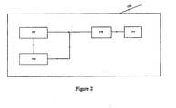
- Fig. 2 illustrates a block diagram of a processing unit of a motion detector in accordance with an exemplary embodiment of the invention.
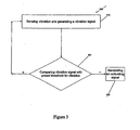
- FIG. 3 illustrates a flow chart for a tampering detection method in accordance with an exemplary embodiment of the invention
- Figure 1 illustrates a block diagram of a motion detector 100 according to one exemplary embodiment of the present invention.
- the motion detection system 100 includes a pyroelectric sensor 110 containing an optical filter, a vibration sensor 120, a lens 130, a first signal amplifier 150 and a second signal amplifier 150a, a first signal filter 160 and a second signal filter 160a, and a processing unit 170.
- the motion detector 100 includes an alarm relay 180 which signals to the control panel when a human is detected. When the control panel is armed, the panel will take measures, such as sounding an alarm, turning on one or more lights and/or notifying the police when an alarm signal is generated.
- the motion detector 100 also contains a tamper relay used to generate a signal when the detector unit has been tampered with.
- the processor 170 leaves this relay activated until the tamper condition has been removed and the motion detector 100 has been verified to once again have the ability to detect a human in the protected area.
- the motion detector 100 includes a status indicator 190 for showing the operational status of the motion detector 100.
- the motion detector 100 will include a power source (not shown).
- the power source can be an internal power source such as a battery.
- the motion detector 100 is adapted to detect a tampering of the motion detector 100.
- the motion detector 100 is capable of detecting either a spraying or brushing of a coating on the lens 130 where the spraying or brushing prevents an accurate detection of motion.
- the motion detector 100 examines or analyzes a parameter in connection with the vibration associated with the detector tampering, to determine the presence of a tampering act in the detection zone and, in addition, the type of the tampering act, such as a brushing or a spraying.
- the lens 130 for example, a Fresnel lens array or window used in conjunction with a mirror array, is disposed in front of the pyroelectric sensor 110 to focus and transmit the light energy onto the sensor.
- a Fresnel lens array can be molded externally and assembled in the housing (not shown) of the motion detection 100 to implement the lens 130.
- the lens 130 can be multi-faceted in order to provide a plurality of detection zones, which can be fanned out in a vertical orientation as well as horizontal orientation to maximize the coverage of the detection system.
- the lens 130 can also be configured to inhibit the passage of light having predetermined wavelengths, and thereby can function as a light filtering element.
- the infrared energy or signal will reach the pyroelectric sensor only through the lens 130. Thus, if the lens is sprayed or brushed with a coating, an infrared signal will not pass through.
- the filter 112 is configured to filter out as much as possible the visible light passing through the lens 130 and attenuate as little as possible the infrared light passing through the lens 130.
- the pyroelectric sensor 110 is responsive to changes in infrared light emanating from objects entering or exiting a detection zone.
- the pyroelectric sensor 110 converts the changes in infrared light into electrical signals. Motion is detected when an infrared emitting source with one temperature, such as a human body passes in front of a source (background) with another temperature. Motion is detected based on the difference in temperature.
- the pyroelectric sensor 110 generates a light output signal representative of a detected parameter of the infrared light, such as the change of the intensity level of infrared light. If the level of the infrared light increases beyond a threshold level, it is determined that an intruder is present in the detection zone, and subsequently an alarm is issued.
- the output signal from the pyroelectric sensor 110 is in the form of a voltage change.
- the detector 100 includes a first signal amplifier 150 and a first signal filter 160 to amplify and filter the voltage change before the signal is inputted to the processing unit 170.
- the vibration sensor 120 can be any suitable sensor that is capable of sensing the vibrations applied on the detector, especially on the lens 130 of the detector. By incorporating such a vibration-sensitive sensor into the detector, the detector can "hear" the applications of masking materials on the lens.
- the vibration sensor 120 includes, but is not limited to, an acoustic sensor, such as a microphone or piezo-transducer.
- the vibration sensor 120 is able to sense the vibrations conducted by air or by a solid.
- the vibration sensor 120 includes an electret microphone, which is very sensitive to solid-conducted sound caused by a spraying or a brushing on the lens of the detector.
- the vibration sensor 120 may include but is not limited to any type of suitable microphone and/or an accelerometer.
- the vibration sensor 120 can be disposed at any location relative to the detector as long as the sensor can sense the vibrations applied on the lens.
- the vibration sensor 120 is embedded in a solid component of the detector, such as mounted on the surface of the PCB of the detector, thereby detecting the sound radiated through the air as well as conducted through the housing to the PCB.
- the vibration sensor 120 senses vibrations and generates a vibration output signal representative of detected parameters of the vibrations.
- the vibration sensor 120 generates a signal according to the amplitude, intensity and/or frequency of the vibrations applied to the lens of the detector.
- the signal is in the form a voltage change.
- the detector 100 includes a second signal amplifier 150a and a second signal filter 160a to amplify and filter the voltage change before the signal is sent to the processing unit 170.
- tampering illustrate different sound patterns, that can be utilized to not only determine the presence of a tampering act but determine the type the tampering act.
- output signals caused by a spraying illustrate different characteristics than output signals caused by a brushing.
- a model indicative of a specific tampering act can be generated accordingly.
- Experimentation can be performed to set up an alarm threshold associated with a specific tampering act, such as a spraying.
- a plurality of thresholds can be generated empirically or statistically for identifying different tampering acts. If it is determined that the output signal caused by a possible tampering act exceeds a predetermined threshold, a tampering alarm is issued and accordingly the type of the tampering act is identified.
- models can be created for detecting and identifying a spraying, a brushing or an application of clear tapes. The models are stored in a storage, which is accessible by the processing unit 170.
- the pyroelectric sensor 110 and the vibration sensor 120 are integrated into a unitary section 110', as shown by the phantom line in Figure 1 .
- the unitary section 110' performs the sensing of infrared light as well as vibration and generates an output signal, which can be representative of either infrared light or sound.
- the signal is processed for detecting motion and a tampering by two different channels implemented by two different sets of amplifiers and filters.
- the unitary section 110' can be made of materials inherent with pyroelectric-effect and piezoelectric-effect, such as a pyroelectric sensor sensitive to vibrations as well.
- Fig. 2 is a block diagram of functional blocks in a processing unit in accordance with an embodiment of the invention.
- the processing unit can be any computer-related entity as long as it is capable of executing the functionality thereof.
- the component includes but is not limited to hardware, software and a combination of hardware and software.
- the processing unit 170 includes a signal receiving element 171, a data reading element 172, a logic comparing element 173 and an activating signal generating element 174.
- the signal receiving element 171 receives the output signal from the pyroelectric sensor 110 and/or the vibration sensor 120, and further feeds the signal to the logic comparing element 173 and the data reading element 172.
- the signal inputted into the data reading element 172 is used to determine which model(s) stored in a storage (not shown) shall be read out and further fed to the logic comparing element 173.
- the storage includes all preset models and thresholds, including but not limited to, rate of change, duration, amplitudes and so on.
- the storage can be any type of memory.
- the data reading element 172 reads out a model in connection with the light output signal, such as a threshold for the infrared light, and feeds the threshold into the logic comparing element 173. Otherwise, the data reading element 172 reads out the models in connection with the vibration output signal, such as thresholds indicative of a brushing, a spraying, an application of clear tapes, and so on, and feeds the thresholds into the logic comparing element 173.
- a model in connection with the light output signal such as a threshold for the infrared light
- the data reading element 172 reads out the models in connection with the vibration output signal, such as thresholds indicative of a brushing, a spraying, an application of clear tapes, and so on, and feeds the thresholds into the logic comparing element 173.
- the logic comparing element 173 compares the inputted signal from the signal receiving element 171 with the thresholds inputted from the data reading element 172, to determine whether the signal exceeds a predetermined threshold. If the signal exceeds a predetermined threshold, the logic comparing element 173 transmits an instruction to the activating signal generating element 174, for generating an activating signal identifying a motion or a tampering act, and, if a tampering act is detected, the type of tampering act.
- the alarm relay 180 shown in Figure 1 , is responsive to the motion activating signal and issues an alarm signal to the panel accordingly.
- the tamper relay is responsive to the tamper activating signal and issues tamper signal to the panel accordingly.
- Fig. 3 illustrates a flow chart for a method 200 for detecting tampering, according to an exemplary embodiment of the invention.
- vibrations applied to the lens of the detector are detected and accordingly a vibration output signal representative of a detected level of the vibration is produced by the vibration sensor 120 shown in Figure 1 .
- the vibrations output signal is in the form a voltage change, which reflects the vibrations applied on the lens of the detector.
- the method 200 includes steps of amplifying and filtering the output signal generated in steps 210.
- the signals are digitized before being processed.
- step 220 it is determined whether the vibration output signal is consistent with a predetermined model indicative of a tampering.
- the vibration output signal is compared with a threshold and waveform retrieved from a storage. If it is determined that the vibrations output signal is consistent with the waveform and exceeds the threshold, an activating signal is produced at step 230, which is transmitted to tamper relay for issuing a tampering alarm. On the other hand, if it is determined that the vibrations output signal does not exceed the threshold or is inconsistent with the waveform, the method returns to step 210.
Landscapes
- Physics & Mathematics (AREA)
- General Physics & Mathematics (AREA)
- Engineering & Computer Science (AREA)
- Computer Security & Cryptography (AREA)
- Burglar Alarm Systems (AREA)
- Geophysics And Detection Of Objects (AREA)
- Photometry And Measurement Of Optical Pulse Characteristics (AREA)
Description
- The present invention relates generally to sensors and security systems. More particularly, the present invention relates to a detector that includes a sensing element adapted for detecting vibration signals generated upon the tampering of the detector.
- Sensors are used to detect events such as a glass break, motion, asset movement, temperature and impact/shock. These sensors can be used as a standalone device or in combination with a security system. A security system includes a life, safety, and property protection system. The sensors communicate with a control panel when the sensor detects an event.
- Motion detectors contain a lens array or window / mirror array system which focuses Infrared (IR) energy produced by a human onto a pyroelectric sensor which converts the changes in IR energy reaching it into electrical signals. The energy produced by human body temperatures is in the range of 5 µM to 15 µM, also known as far IR. The lens array in one style of a motion detector and the window in another style containing a mirror array must allow far IR energy to pass in order for the energy to be focused on the pyroelectric sensor. If the lens or window is tampered with in such a way to prohibit passage of far IR energy, the motion detector will fail to detect an intruder.
- Motion sensors or detectors can be intentionally tampered by an intruder. For example, the intruder can mask the window or lens of the detector by a coating, such as paints. Masking of the detector prevents the IR energy from reaching the pyroelectric sensor of the detector, thereby undermining the detection functionality of detecting motion within a protected area. Generally, spraying or brushing a coating or film on the window or lens of the sensor blocking the infrared signal can mask a detector, such as a passive infrared sensor (PIR).
- In light of the foregoing problems, many motion detectors are designed to include systems to detect intentional masking or blocking of the sensing element of the sensor. These systems are commonly referred to as anti-mask systems. For example, these motion detectors employ active near infrared sensors (wavelengths just beyond the visible spectrum typically around 900nM) as their basic instrument for anti-masking. Honeywell "Viewguard PIR AM" is an example of such motion detectors using active near infrared sensing system, and is market available. In an alternate embodiment, these motion detectors may use a microwave sensing system as anti-mask systems. Honeywell DT7550 is an example of such motion detectors using microwave sensing system, and is market available.
Alternatively,EP 0 476 397 A1 discloses a motion detector with an anti-masking system involving sending and receiving an ultrasonic signal and monitoring variations on the received signal to identify masking of the detector - However, these detectors have inherent weakness to paints applied with brushes tenderly or spray cans. The act of a spray application only causes a slight transient change in the active near infrared sensor signal. However, this transient change can be caused by other events not associated with masking, such as an electrical spike or a pass of an object. The act of applying clear paints via a brush generally causes significant swings in the active near infrared sensor signal. However, a fluttering moth or a feather duster can cause the same swings as the brush. Thus, detection of only transient change or swings in the detector signal is not sufficient and sometimes not reliable to detect masking, because a false alarm indicating tampering may be issued.
- Furthermore, so-called clear sprayed on materials, such as hair spray or clear paint, are inherently difficult to detect. Other difficult materials are clear adhesives, such as clear tapes, applied very smoothly to the lens without wrinkles or air bubbles, which are nearly impossible to detect after the application. Clear paints and clear adhesives are transparent to visible and near IR (Infrared) energy but block far IR energy. Thus, the window of the detector covered in clear paint or adhesive blocks the thermal energy from an intruder from reaching the pyroelectric sensor, which renders the detector blind.
- Therefore, it would be very advantageous to provide a motion detector and a method having an anti-mask mechanism capable of effectively and reliably detecting any possible intentional masking of the detector.
- The present invention is directed to a motion detector that is capable of detecting masking of the detector. In particularly, the detector of the invention can detect masking of the detector in the form of spraying or brushing a coating on the lens or window for the purposes of blocking far IR energy from reaching the pyroelectric sensor. The invention is defined by the independent claims.
- The detector includes a vibration-sensing unit sensitive to vibrations applied to the detector, which produces a vibration output signal representative of a detected parameter of the vibrations, an infrared light-sensing unit sensitive to light having wavelengths in the 5-15 micron region, which produces a light output signal representative of a detected parameter of the light in the predetermined spectrum and a processing unit for determining if the vibration output signal is consistent with a predetermined model indicative of a tampering and producing an activating signal accordingly.
- The present invention is also directed to a method of detecting tampering of a motion detector. The method includes the steps of sensing vibrations applied to the detector and producing a vibration output signal representative of a detected level of the vibration, determining if the vibration output signal is consistent with a predetermined model indicative of a tampering and producing an activating signal accordingly.
- Although the detector and method according to one embodiment of the present invention will be described in connection with a security system, it should be recognized that the application of the detector and method according to the present invention is not limited to a security system. Rather, the detector and method are applicable to any other suitable circumstances.
- These and other features, benefits, and advantages of the present invention will become apparent by reference to the following text and figures, with like reference numbers referring to like structures across the view, wherein
-
Fig. 1 is a block diagram of a motion detector in accordance with an exemplary embodiment of the invention; -
Fig. 2 illustrates a block diagram of a processing unit of a motion detector in accordance with an exemplary embodiment of the invention; and -
Fig. 3 illustrates a flow chart for a tampering detection method in accordance with an exemplary embodiment of the invention - The present invention now will be described in detail hereinafter with reference to the accompanying drawings, in which exemplary embodiments of the invention are shown. However, this invention may be embodied in many different forms and should not be construed as limited to the embodiments set forth herein. Like numerals refer to like elements throughout.
-
Figure 1 illustrates a block diagram of amotion detector 100 according to one exemplary embodiment of the present invention. Generally, themotion detection system 100 includes apyroelectric sensor 110 containing an optical filter, avibration sensor 120, alens 130, afirst signal amplifier 150 and asecond signal amplifier 150a, afirst signal filter 160 and a second signal filter 160a, and aprocessing unit 170. Additionally, themotion detector 100 includes analarm relay 180 which signals to the control panel when a human is detected. When the control panel is armed, the panel will take measures, such as sounding an alarm, turning on one or more lights and/or notifying the police when an alarm signal is generated. Themotion detector 100 also contains a tamper relay used to generate a signal when the detector unit has been tampered with. In the exemplary embodiment of the present invention, theprocessor 170 leaves this relay activated until the tamper condition has been removed and themotion detector 100 has been verified to once again have the ability to detect a human in the protected area. Additionally, themotion detector 100 includes astatus indicator 190 for showing the operational status of themotion detector 100. Additionally, themotion detector 100 will include a power source (not shown). The power source can be an internal power source such as a battery. - In accordance with the embodiment of the present invention, the
motion detector 100 is adapted to detect a tampering of themotion detector 100. Themotion detector 100 is capable of detecting either a spraying or brushing of a coating on thelens 130 where the spraying or brushing prevents an accurate detection of motion. Generally, themotion detector 100 examines or analyzes a parameter in connection with the vibration associated with the detector tampering, to determine the presence of a tampering act in the detection zone and, in addition, the type of the tampering act, such as a brushing or a spraying. - The
lens 130, for example, a Fresnel lens array or window used in conjunction with a mirror array, is disposed in front of thepyroelectric sensor 110 to focus and transmit the light energy onto the sensor. For example, a Fresnel lens array can be molded externally and assembled in the housing (not shown) of themotion detection 100 to implement thelens 130. Thelens 130 can be multi-faceted in order to provide a plurality of detection zones, which can be fanned out in a vertical orientation as well as horizontal orientation to maximize the coverage of the detection system. - The
lens 130 can also be configured to inhibit the passage of light having predetermined wavelengths, and thereby can function as a light filtering element. The infrared energy or signal will reach the pyroelectric sensor only through thelens 130. Thus, if the lens is sprayed or brushed with a coating, an infrared signal will not pass through. In an exemplary embodiment of thepyroelectric sensor 110, the filter 112 is configured to filter out as much as possible the visible light passing through thelens 130 and attenuate as little as possible the infrared light passing through thelens 130. - The
pyroelectric sensor 110 is responsive to changes in infrared light emanating from objects entering or exiting a detection zone. Thepyroelectric sensor 110 converts the changes in infrared light into electrical signals. Motion is detected when an infrared emitting source with one temperature, such as a human body passes in front of a source (background) with another temperature. Motion is detected based on the difference in temperature. - The
pyroelectric sensor 110 generates a light output signal representative of a detected parameter of the infrared light, such as the change of the intensity level of infrared light. If the level of the infrared light increases beyond a threshold level, it is determined that an intruder is present in the detection zone, and subsequently an alarm is issued. For example, the output signal from thepyroelectric sensor 110 is in the form of a voltage change. Preferably, thedetector 100 includes afirst signal amplifier 150 and afirst signal filter 160 to amplify and filter the voltage change before the signal is inputted to theprocessing unit 170. - The
vibration sensor 120 can be any suitable sensor that is capable of sensing the vibrations applied on the detector, especially on thelens 130 of the detector. By incorporating such a vibration-sensitive sensor into the detector, the detector can "hear" the applications of masking materials on the lens. Thevibration sensor 120 includes, but is not limited to, an acoustic sensor, such as a microphone or piezo-transducer. Thevibration sensor 120 is able to sense the vibrations conducted by air or by a solid. In one embodiment, thevibration sensor 120 includes an electret microphone, which is very sensitive to solid-conducted sound caused by a spraying or a brushing on the lens of the detector. In addition, thevibration sensor 120 may include but is not limited to any type of suitable microphone and/or an accelerometer. - The
vibration sensor 120 can be disposed at any location relative to the detector as long as the sensor can sense the vibrations applied on the lens. In one embodiment, thevibration sensor 120 is embedded in a solid component of the detector, such as mounted on the surface of the PCB of the detector, thereby detecting the sound radiated through the air as well as conducted through the housing to the PCB. - The
vibration sensor 120 senses vibrations and generates a vibration output signal representative of detected parameters of the vibrations. For example, thevibration sensor 120 generates a signal according to the amplitude, intensity and/or frequency of the vibrations applied to the lens of the detector. For example, the signal is in the form a voltage change. In one embodiment, thedetector 100 includes asecond signal amplifier 150a and a second signal filter 160a to amplify and filter the voltage change before the signal is sent to theprocessing unit 170. - Generally, different types of tampering illustrate different sound patterns, that can be utilized to not only determine the presence of a tampering act but determine the type the tampering act.
- For example, output signals caused by a spraying illustrate different characteristics than output signals caused by a brushing. Thus, a model indicative of a specific tampering act can be generated accordingly. Experimentation can be performed to set up an alarm threshold associated with a specific tampering act, such as a spraying. A plurality of thresholds can be generated empirically or statistically for identifying different tampering acts. If it is determined that the output signal caused by a possible tampering act exceeds a predetermined threshold, a tampering alarm is issued and accordingly the type of the tampering act is identified. For example, models can be created for detecting and identifying a spraying, a brushing or an application of clear tapes. The models are stored in a storage, which is accessible by the
processing unit 170. - In one embodiment, the
pyroelectric sensor 110 and thevibration sensor 120 are integrated into a unitary section 110', as shown by the phantom line inFigure 1 . The unitary section 110' performs the sensing of infrared light as well as vibration and generates an output signal, which can be representative of either infrared light or sound. In this case, the signal is processed for detecting motion and a tampering by two different channels implemented by two different sets of amplifiers and filters. Moreover, the unitary section 110' can be made of materials inherent with pyroelectric-effect and piezoelectric-effect, such as a pyroelectric sensor sensitive to vibrations as well. -
Fig. 2 is a block diagram of functional blocks in a processing unit in accordance with an embodiment of the invention. The processing unit can be any computer-related entity as long as it is capable of executing the functionality thereof. For example, the component includes but is not limited to hardware, software and a combination of hardware and software. - As depicted in
Fig. 2 , theprocessing unit 170 includes asignal receiving element 171, adata reading element 172, alogic comparing element 173 and an activatingsignal generating element 174. - The
signal receiving element 171 receives the output signal from thepyroelectric sensor 110 and/or thevibration sensor 120, and further feeds the signal to thelogic comparing element 173 and thedata reading element 172. The signal inputted into thedata reading element 172 is used to determine which model(s) stored in a storage (not shown) shall be read out and further fed to thelogic comparing element 173. The storage includes all preset models and thresholds, including but not limited to, rate of change, duration, amplitudes and so on. The storage can be any type of memory. - For example, if it is determined by the
data reading element 172 that the input signal is indicative of the change of intensity level of infrared light, thedata reading element 172 reads out a model in connection with the light output signal, such as a threshold for the infrared light, and feeds the threshold into thelogic comparing element 173. Otherwise, thedata reading element 172 reads out the models in connection with the vibration output signal, such as thresholds indicative of a brushing, a spraying, an application of clear tapes, and so on, and feeds the thresholds into thelogic comparing element 173. - The
logic comparing element 173 compares the inputted signal from thesignal receiving element 171 with the thresholds inputted from thedata reading element 172, to determine whether the signal exceeds a predetermined threshold. If the signal exceeds a predetermined threshold, thelogic comparing element 173 transmits an instruction to the activatingsignal generating element 174, for generating an activating signal identifying a motion or a tampering act, and, if a tampering act is detected, the type of tampering act. Thealarm relay 180, shown inFigure 1 , is responsive to the motion activating signal and issues an alarm signal to the panel accordingly. The tamper relay is responsive to the tamper activating signal and issues tamper signal to the panel accordingly. -
Fig. 3 illustrates a flow chart for amethod 200 for detecting tampering, according to an exemplary embodiment of the invention. - At
step 210, vibrations applied to the lens of the detector are detected and accordingly a vibration output signal representative of a detected level of the vibration is produced by thevibration sensor 120 shown inFigure 1 . For example, the vibrations output signal is in the form a voltage change, which reflects the vibrations applied on the lens of the detector. Optionally, themethod 200 includes steps of amplifying and filtering the output signal generated insteps 210. Preferably, the signals are digitized before being processed. - At
step 220, it is determined whether the vibration output signal is consistent with a predetermined model indicative of a tampering. Atstep 220, the vibration output signal is compared with a threshold and waveform retrieved from a storage. If it is determined that the vibrations output signal is consistent with the waveform and exceeds the threshold, an activating signal is produced atstep 230, which is transmitted to tamper relay for issuing a tampering alarm. On the other hand, if it is determined that the vibrations output signal does not exceed the threshold or is inconsistent with the waveform, the method returns to step 210. - The invention has been described herein with reference to particular exemplary embodiments. Certain alterations and modifications may be apparent to those skilled in the art, without departing from the scope of the invention. The exemplary embodiments are meant to be illustrative, not limiting of the scope of the invention, which is defined by the appended claims.
Claims (15)
- A motion detector (100) for detecting a masking of a lens of the motion detector, comprising:a lens (130);a vibration-sensing unit (120) sensitive to vibrations applied to the lens and producing a vibration output signal representative of a detected parameter of the vibrations;an infrared light-sensing unit (110) sensitive to infrared light in a predetermined spectrum and producing a light output signal representative of a detected parameter of the light in the predetermined spectrum; anda processing unit (170) for determining if the vibration output signal is consistent with a predetermined model indicative of a masking of the lens (130) and producing an activating signal accordingly.
- The detector of claim 1, further comprising a signal amplifier (150) for amplifying the vibration output signal and a signal filter (160) for filtering the vibration output signal.
- The detector of claim 1, wherein the detected parameter of the vibrations comprises at least one of frequency, amplitude and intensity of the vibrations.
- The detector of claim 1, wherein the vibration-sensing unit and the light-sensing unit are integrated into a unitary section, which is made of materials inherent with pyroelectric-effect and piezoelectric-effect.
- The detector of claim 4, wherein the unitary section is a pyroelectric sensor responsive to infrared light and vibration.
- The detector of claim 1, wherein the vibration sensing unit is selected from the group consisting of a piezo-electric transducer, an electret microphone, any type of microphone and an accelerometer.
- The detector of claim 1, wherein the light-sensing unit is a pyroelectric sensor sensitive to light in the infrared spectrum.
- The detector of claim 1, wherein the predetermined model indicative of a tampering comprises a tampering pattern indicative of a spraying on the lens (130), the tampering pattern comprises a tampering alarm threshold empirically generated and indicative of a spraying, and the processing unit compares the vibration output signal with the tampering alarm threshold and produces an activating signal indicating a spraying if the vibration output signal exceeds the threshold.
- The detector of claim 1, wherein the predetermined model indicative of a tampering comprises a tampering pattern indicative of a brushing on the lens (130) the tampering pattern comprises a tampering alarm threshold empirically generated and indicative of a brushing, and the processing unit compares the vibration output signal with the tampering alarm threshold and produces an activating signal indicating a brushing if the vibration output signal exceeds the threshold.
- The detector of claim 1, wherein the predetermined model indicative of a tampering comprises a tampering pattern indicative of an application of a film onto lens of the detector, the tampering pattern comprises a tampering alarm threshold empirically generated and indicative of an application of a film on the lens of the detector, and the processing unit compares the vibration output signal with the tampering alarm threshold and produces an activating signal indicating an application of a film onto the lens if the vibration output signal exceeds the threshold.
- The detector of claim 1, wherein the lens (130) is transmissive or reflective of the wavelength in the visible or near infrared and the detector (100) further comprises on active visible or near infrared sensing unit for detecting presence of or application of mask materials in the vicinity of the lens or window.
- The detector of claim 1, further comprising a microwave sensing unit for detecting the presence of or application of materials that block far IR energy.
- A method of detecting a masking of a lens of a motion detector, comprising the steps of:providing a motion detector with a lens;sensing vibrations (210) applied to the lens and producing a vibration output signal representative of a detected level of the vibration; anddetermining (220) if the vibration output signal is consistent with a predetermined model indicative of a masking and producing (230) an activating signal accordingly.
- The method of claim 13, wherein producing a vibration output signal representative of a detected level of the vibration comprises producing a vibration output signal representative of at least one of frequency, amplitude and intensity of the vibrations.
- The method of claim 13, wherein determining if the vibration output signal is consistent with a predetermined model indicative of a tampering and producing an activating signal accordingly comprises determining if the vibration output signal is consistent with a tampering pattern indicative of a spraying and producing an activating signal indicating a spraying accordingly.
Applications Claiming Priority (1)
| Application Number | Priority Date | Filing Date | Title |
|---|---|---|---|
| US12/140,555 US7852210B2 (en) | 2007-12-31 | 2008-06-17 | Motion detector for detecting tampering and method for detecting tampering |
Publications (2)
| Publication Number | Publication Date |
|---|---|
| EP2136342A1 EP2136342A1 (en) | 2009-12-23 |
| EP2136342B1 true EP2136342B1 (en) | 2011-12-28 |
Family
ID=41110750
Family Applications (1)
| Application Number | Title | Priority Date | Filing Date |
|---|---|---|---|
| EP09154254A Not-in-force EP2136342B1 (en) | 2008-06-17 | 2009-03-03 | Motion detector for detecting tampering and method for detecting tampering |
Country Status (3)
| Country | Link |
|---|---|
| US (1) | US7852210B2 (en) |
| EP (1) | EP2136342B1 (en) |
| CN (1) | CN101608951B (en) |
Families Citing this family (29)
| Publication number | Priority date | Publication date | Assignee | Title |
|---|---|---|---|---|
| US8319638B2 (en) * | 2007-11-14 | 2012-11-27 | Honeywell International Inc. | Motion detector for detecting tampering and method for detecting tampering |
| US8558889B2 (en) * | 2010-04-26 | 2013-10-15 | Sensormatic Electronics, LLC | Method and system for security system tampering detection |
| US20120194341A1 (en) * | 2011-01-27 | 2012-08-02 | Peichel David J | Accelerometer feedback control loop for patient alert |
| US8773263B2 (en) | 2011-09-01 | 2014-07-08 | Ecolink Intelligent Technology, Inc. | Security apparatus and method |
| US9142108B2 (en) | 2011-09-01 | 2015-09-22 | Ecolink Intelligent Technology, Inc. | Security apparatus and method |
| US9123222B2 (en) | 2012-03-15 | 2015-09-01 | Ninve Jr. Inc. | Apparatus and method for detecting tampering with an infra-red motion sensor |
| CN102889932B (en) * | 2012-09-25 | 2014-06-04 | 山东神戎电子股份有限公司 | Thermal imager and method for resisting strong-light damage |
| WO2014107625A1 (en) * | 2013-01-04 | 2014-07-10 | USS Technologies, LLC | Public view monitor with tamper deterrent and security systems |
| US9324222B2 (en) * | 2013-02-28 | 2016-04-26 | Honeywell International Inc. | Tamper resistant motion detector |
| CN103984040A (en) * | 2014-05-20 | 2014-08-13 | 刘达 | Biological recognition method based on infrared sensor array algorithm |
| CN106068530A (en) * | 2016-04-18 | 2016-11-02 | 汤美 | A kind of campus dormitory monitoring fire prevention system |
| CN109564715B (en) * | 2016-08-18 | 2021-08-13 | 罗伯特·博世有限公司 | Motion sensor with anti-masking protection |
| CN107314820A (en) * | 2017-07-04 | 2017-11-03 | 南方科技大学 | Active infrared sensing device and system |
| WO2020000374A1 (en) * | 2018-06-29 | 2020-01-02 | 深圳市大疆创新科技有限公司 | Acoustic vibration detection device and racing remote control car |
| CN112084813B (en) * | 2019-06-12 | 2024-06-04 | 杭州萤石软件有限公司 | Abnormal target detection method, device and storage medium |
| US10762773B1 (en) | 2019-08-19 | 2020-09-01 | Ademco Inc. | Systems and methods for building and using a false alarm predicting model to determine whether to alert a user and/or relevant authorities about an alarm signal from a security system |
| US11470265B2 (en) | 2019-12-16 | 2022-10-11 | Plusai, Inc. | System and method for sensor system against glare and control thereof |
| US11738694B2 (en) * | 2019-12-16 | 2023-08-29 | Plusai, Inc. | System and method for anti-tampering sensor assembly |
| US11724669B2 (en) | 2019-12-16 | 2023-08-15 | Plusai, Inc. | System and method for a sensor protection system |
| US11650415B2 (en) | 2019-12-16 | 2023-05-16 | Plusai, Inc. | System and method for a sensor protection mechanism |
| US11313704B2 (en) | 2019-12-16 | 2022-04-26 | Plusai, Inc. | System and method for a sensor protection assembly |
| US11077825B2 (en) | 2019-12-16 | 2021-08-03 | Plusai Limited | System and method for anti-tampering mechanism |
| US11754689B2 (en) | 2019-12-16 | 2023-09-12 | Plusai, Inc. | System and method for detecting sensor adjustment need |
| US11403923B2 (en) | 2020-12-09 | 2022-08-02 | Ademco Inc. | Selectively enabled tamper detection |
| WO2022120643A1 (en) | 2020-12-09 | 2022-06-16 | Ademco Inc. | Tamper detection |
| US12488677B2 (en) | 2020-12-09 | 2025-12-02 | Resideo Llc | Bracket tamper detection |
| US11657687B2 (en) | 2021-05-17 | 2023-05-23 | Ecolink Intelligent Technology, Inc. | Smart security barrier sensor |
| US12163974B2 (en) * | 2022-01-26 | 2024-12-10 | Robert Bosch Gmbh | Motion detector with accelerometer and false tampering detection |
| US11772667B1 (en) | 2022-06-08 | 2023-10-03 | Plusai, Inc. | Operating a vehicle in response to detecting a faulty sensor using calibration parameters of the sensor |
Family Cites Families (12)
| Publication number | Priority date | Publication date | Assignee | Title |
|---|---|---|---|---|
| US4451733A (en) * | 1982-05-17 | 1984-05-29 | Cerberus Ag | Infrared intrusion detector with optical pattern locators |
| CH680881A5 (en) | 1990-09-05 | 1992-11-30 | Cerberus Ag | |
| NL9200283A (en) | 1992-02-17 | 1993-09-16 | Aritech Bv | MONITORING SYSTEM. |
| GB9204592D0 (en) * | 1992-03-03 | 1992-04-15 | The Technology Partnership Plc | Movement detector using mechanical vibrations |
| JP2001228020A (en) * | 2000-02-18 | 2001-08-24 | Optex Co Ltd | Crime prevention sensor with obstruction detecting function |
| JP3451238B2 (en) | 2000-05-09 | 2003-09-29 | マツダマイクロニクス株式会社 | Thermopile radiation far-infrared detector for security |
| US6351234B1 (en) | 2000-05-15 | 2002-02-26 | Digital Security Controls Ltd. | Combination microwave passive infrared motion detector with anti-masking evaluation |
| US7004784B2 (en) * | 2004-02-26 | 2006-02-28 | Robert Bosch Gmbh | Tamper detection for security system |
| JP2005276656A (en) * | 2004-03-25 | 2005-10-06 | Optex Co Ltd | Tamper switch structure and crime-prevention sensor equipped therewith |
| US7880603B2 (en) * | 2006-10-09 | 2011-02-01 | Robert Bosch Gmbh | System and method for controlling an anti-masking system |
| CN101034008A (en) * | 2007-03-30 | 2007-09-12 | 上海神明控制工程有限公司 | Split burning fame detecting system |
| CN201053902Y (en) * | 2007-06-18 | 2008-04-30 | 奥泰斯电子(东莞)有限公司 | Infrared reflection type security detector |
-
2008
- 2008-06-17 US US12/140,555 patent/US7852210B2/en not_active Expired - Fee Related
-
2009
- 2009-03-03 EP EP09154254A patent/EP2136342B1/en not_active Not-in-force
- 2009-03-13 CN CN200910134657.6A patent/CN101608951B/en not_active Expired - Fee Related
Also Published As
| Publication number | Publication date |
|---|---|
| CN101608951A (en) | 2009-12-23 |
| US20090167538A1 (en) | 2009-07-02 |
| US7852210B2 (en) | 2010-12-14 |
| EP2136342A1 (en) | 2009-12-23 |
| CN101608951B (en) | 2014-07-16 |
Similar Documents
| Publication | Publication Date | Title |
|---|---|---|
| US7852210B2 (en) | Motion detector for detecting tampering and method for detecting tampering | |
| US5243326A (en) | Device for protecting components of security systems against obstruction | |
| US5428345A (en) | Method of and apparatus for operating a security system to produce an alarm signal | |
| KR101794733B1 (en) | Security and intrusion monitoring system based on the detection of sound variation pattern and the method | |
| US8039799B2 (en) | Motion detection system and method | |
| US5942976A (en) | Passive infrared intrusion detector and its use | |
| WO2004027557A2 (en) | Detector with ambient photon sensor and other sensors | |
| WO2012109710A1 (en) | Alarm device for alerting hazardous conditions | |
| US8035514B2 (en) | Method to improve white light immunity of infrared motion detectors | |
| US8451135B2 (en) | Anti-masking system and method for motion detectors | |
| US8319638B2 (en) | Motion detector for detecting tampering and method for detecting tampering | |
| EP2167926A1 (en) | Optical filter for improved white light immunity in an intrusion detector | |
| US6262661B1 (en) | Passive infrared detector | |
| CA2241088C (en) | Event detection device with fault monitoring capability | |
| US6348863B1 (en) | Method and apparatus for detecting moving objects, particularly intrusions | |
| EP2182495B1 (en) | Improvements in or relating to an alarm apparatus and method | |
| WO2007147322A1 (en) | Monitoring devices and surveillance devices | |
| EP0375270B1 (en) | Radiation detection arrangements and methods | |
| JPH1196467A (en) | Security sensor provided with interference detection function using stray light | |
| EP1866884B1 (en) | Intrusion detector | |
| JP2802191B2 (en) | Security intruder detection device | |
| JP2521505B2 (en) | Passive infrared security sensor with visual field obstruction monitoring mechanism | |
| JP2000194958A (en) | Composite detection device | |
| Rani et al. | Active infrared motion detector for house security system | |
| GB2258073A (en) | Intruder detector |
Legal Events
| Date | Code | Title | Description |
|---|---|---|---|
| PUAI | Public reference made under article 153(3) epc to a published international application that has entered the european phase |
Free format text: ORIGINAL CODE: 0009012 |
|
| 17P | Request for examination filed |
Effective date: 20090303 |
|
| AK | Designated contracting states |
Kind code of ref document: A1 Designated state(s): AT BE BG CH CY CZ DE DK EE ES FI FR GB GR HR HU IE IS IT LI LT LU LV MC MK MT NL NO PL PT RO SE SI SK TR |
|
| AX | Request for extension of the european patent |
Extension state: AL BA RS |
|
| AKX | Designation fees paid |
Designated state(s): FR GB |
|
| REG | Reference to a national code |
Ref country code: DE Ref legal event code: 8566 |
|
| GRAC | Information related to communication of intention to grant a patent modified |
Free format text: ORIGINAL CODE: EPIDOSCIGR1 |
|
| GRAP | Despatch of communication of intention to grant a patent |
Free format text: ORIGINAL CODE: EPIDOSNIGR1 |
|
| GRAS | Grant fee paid |
Free format text: ORIGINAL CODE: EPIDOSNIGR3 |
|
| GRAA | (expected) grant |
Free format text: ORIGINAL CODE: 0009210 |
|
| AK | Designated contracting states |
Kind code of ref document: B1 Designated state(s): FR GB |
|
| REG | Reference to a national code |
Ref country code: GB Ref legal event code: FG4D |
|
| PLBE | No opposition filed within time limit |
Free format text: ORIGINAL CODE: 0009261 |
|
| STAA | Information on the status of an ep patent application or granted ep patent |
Free format text: STATUS: NO OPPOSITION FILED WITHIN TIME LIMIT |
|
| 26N | No opposition filed |
Effective date: 20121001 |
|
| PGFP | Annual fee paid to national office [announced via postgrant information from national office to epo] |
Ref country code: FR Payment date: 20140225 Year of fee payment: 6 |
|
| PGFP | Annual fee paid to national office [announced via postgrant information from national office to epo] |
Ref country code: GB Payment date: 20140225 Year of fee payment: 6 |
|
| GBPC | Gb: european patent ceased through non-payment of renewal fee |
Effective date: 20150303 |
|
| REG | Reference to a national code |
Ref country code: FR Ref legal event code: ST Effective date: 20151130 |
|
| PG25 | Lapsed in a contracting state [announced via postgrant information from national office to epo] |
Ref country code: GB Free format text: LAPSE BECAUSE OF NON-PAYMENT OF DUE FEES Effective date: 20150303 |
|
| PG25 | Lapsed in a contracting state [announced via postgrant information from national office to epo] |
Ref country code: FR Free format text: LAPSE BECAUSE OF NON-PAYMENT OF DUE FEES Effective date: 20150331 |