EP2136069A1 - Fuel supply device for internal combustion engine - Google Patents
Fuel supply device for internal combustion engine Download PDFInfo
- Publication number
- EP2136069A1 EP2136069A1 EP08740052A EP08740052A EP2136069A1 EP 2136069 A1 EP2136069 A1 EP 2136069A1 EP 08740052 A EP08740052 A EP 08740052A EP 08740052 A EP08740052 A EP 08740052A EP 2136069 A1 EP2136069 A1 EP 2136069A1
- Authority
- EP
- European Patent Office
- Prior art keywords
- fuel
- delivery pipe
- path
- fuel injection
- passageway
- Prior art date
- Legal status (The legal status is an assumption and is not a legal conclusion. Google has not performed a legal analysis and makes no representation as to the accuracy of the status listed.)
- Granted
Links
Images
Classifications
-
- F—MECHANICAL ENGINEERING; LIGHTING; HEATING; WEAPONS; BLASTING
- F02—COMBUSTION ENGINES; HOT-GAS OR COMBUSTION-PRODUCT ENGINE PLANTS
- F02M—SUPPLYING COMBUSTION ENGINES IN GENERAL WITH COMBUSTIBLE MIXTURES OR CONSTITUENTS THEREOF
- F02M63/00—Other fuel-injection apparatus having pertinent characteristics not provided for in groups F02M39/00 - F02M57/00 or F02M67/00; Details, component parts, or accessories of fuel-injection apparatus, not provided for in, or of interest apart from, the apparatus of groups F02M39/00 - F02M61/00 or F02M67/00; Combination of fuel pump with other devices, e.g. lubricating oil pump
- F02M63/02—Fuel-injection apparatus having several injectors fed by a common pumping element, or having several pumping elements feeding a common injector; Fuel-injection apparatus having provisions for cutting-out pumps, pumping elements, or injectors; Fuel-injection apparatus having provisions for variably interconnecting pumping elements and injectors alternatively
- F02M63/0225—Fuel-injection apparatus having a common rail feeding several injectors ; Means for varying pressure in common rails; Pumps feeding common rails
- F02M63/0275—Arrangement of common rails
- F02M63/0285—Arrangement of common rails having more than one common rail
- F02M63/0295—Arrangement of common rails having more than one common rail for V- or star- or boxer-engines
-
- F—MECHANICAL ENGINEERING; LIGHTING; HEATING; WEAPONS; BLASTING
- F02—COMBUSTION ENGINES; HOT-GAS OR COMBUSTION-PRODUCT ENGINE PLANTS
- F02M—SUPPLYING COMBUSTION ENGINES IN GENERAL WITH COMBUSTIBLE MIXTURES OR CONSTITUENTS THEREOF
- F02M55/00—Fuel-injection apparatus characterised by their fuel conduits or their venting means; Arrangements of conduits between fuel tank and pump F02M37/00
- F02M55/02—Conduits between injection pumps and injectors, e.g. conduits between pump and common-rail or conduits between common-rail and injectors
- F02M55/025—Common rails
-
- F—MECHANICAL ENGINEERING; LIGHTING; HEATING; WEAPONS; BLASTING
- F02—COMBUSTION ENGINES; HOT-GAS OR COMBUSTION-PRODUCT ENGINE PLANTS
- F02M—SUPPLYING COMBUSTION ENGINES IN GENERAL WITH COMBUSTIBLE MIXTURES OR CONSTITUENTS THEREOF
- F02M2200/00—Details of fuel-injection apparatus, not otherwise provided for
- F02M2200/31—Fuel-injection apparatus having hydraulic pressure fluctuations damping elements
- F02M2200/315—Fuel-injection apparatus having hydraulic pressure fluctuations damping elements for damping fuel pressure fluctuations
-
- F—MECHANICAL ENGINEERING; LIGHTING; HEATING; WEAPONS; BLASTING
- F02—COMBUSTION ENGINES; HOT-GAS OR COMBUSTION-PRODUCT ENGINE PLANTS
- F02M—SUPPLYING COMBUSTION ENGINES IN GENERAL WITH COMBUSTIBLE MIXTURES OR CONSTITUENTS THEREOF
- F02M37/00—Apparatus or systems for feeding liquid fuel from storage containers to carburettors or fuel-injection apparatus; Arrangements for purifying liquid fuel specially adapted for, or arranged on, internal-combustion engines
- F02M37/0047—Layout or arrangement of systems for feeding fuel
- F02M37/0052—Details on the fuel return circuit; Arrangement of pressure regulators
Definitions
- the present invention relates to a fuel supply device for an internal combustion engine comprising two fuel injection systems, each having a delivery pipe for storing fuel and a fuel injection valve provided in the delivery pipe.
- a fuel supply device for an internal combustion engine includes delivery pipes for storing fuel that is fed under pressure by a fuel pump and supplies fuel by controlling opening of a fuel injection valve connected to each delivery pipe.
- the pressure of the fuel is unavoidably pulsated inside the delivery pipes while the injection of the fuel is alternately executed and stopped. This pulsation of the fuel pressure would lead to various kinds of disadvantages such as occurrence of noises or degradation in efficiency of pumping fuel by the fuel pump.
- a fuel supply device for an internal combustion engine includes two fuel injection systems and a pulsation damper.
- Each of the two fuel injection systems has a delivery pipe for storing fuel and a fuel injection valve provided on the delivery pipe.
- the delivery pipe of one of the fuel injection systems is a first delivery pipe while the delivery pipe of the other fuel injection system is a second delivery pipe.
- the device drives intermittently the fuel injection valve to open while pumping fuel to the two fuel injection systems with a common fuel pump, thereby supplying the fuel within the first and second delivery pipes.
- the device further comprises a first passageway through which fuel passes, a second passageway through which fuel passes, and a pressure introduction path for introducing fuel pressure into the pulsation damper.
- the first passageway includes the first delivery pipe and a communication path for communicating the first delivery pipe with the fuel pump.
- the second passageway is branched at a location closer to the fuel pump than to the fuel injection valve in the first passageway and connected to the second delivery pipe.
- the second passageway includes the second delivery pipe and a branch path.
- the branch path has an opening at the branch location.
- An opposing portion in the first passageway to which the opening of the pressure introduction path is opposed includes part of the opening of the branch path.
- the entire opening of the branch path may be included in the opposing portion.
- the pressure introduction path may be a placement channel branched from the first passageway.
- the pulsation damper may include an introduction path for introducing fuel pressure therein.
- the introduction path may be provided in the placement channel with the introduction path being kept open inside the placement channel.
- a return path for returning excessive fuel inside the first and second passageways to a fuel tank may be connected to a portion of the first passageway closer to the fuel pump than to the branch location.
- the internal combustion engine may have cylinders in a V-shaped arrangement. Each fuel injection system may be disposed in corresponding bank of the internal combustion engine.
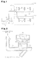
- Fig. 1 is a schematic view illustrating a fuel supply device for an internal combustion engine according to an embodiment of the present invention
- a fuel supply device for an internal combustion engine of the invention is applicable to an internal combustion engine having cylinders arranged in a V-shape.
- Fig. 1 is a schematic view illustrating the configuration of a fuel supply device for an internal combustion engine according to this embodiment. As illustrated in Fig. 1 , a delivery pipe 12A is provided in a first bank 11A of an internal combustion engine 10 and a delivery pipe 12B is provided in a second bank 11B.
- the first delivery pipe 12A is connected at its one end with a communication path 13, which in turn communicates with a fuel tank 15 via a motor-driven fuel pump 14.
- a branch path 17 is provided to the delivery pipe 12A branch and extend from an intermediate portion of the delivery pipe 12A, more specifically, the portion which is closer to the communication path 13 than a plurality of fuel injection valves 16 provided on the delivery pipe 12A.
- the branch path 17 is connected to an end of the second delivery pipe 12B.
- the branch path 17 allows the delivery pipes 12A and 12B to communicate with each other.
- the fuel is pumped by driving of the fuel pump 14 through the communication path 13 and the branch path 17 and introduced into each delivery pipe 12A and 12B to be stored therein.
- the fuel supply device includes, as passageways through which fuel passes, two passageway systems of a first passageway and a second passageway.
- the first passageway is made up of the delivery pipe 12A and the communication path 13.
- the second passageway is made up of the delivery pipe 12B and the branch path 17.
- a pressure regulator 18 is disposed between the delivery pipe 12A and the fuel pump 14 in the communication path 13, and the pressure regulator 18 is connected with a return path 19.
- the pressure regulator 18 is a pressure activated valve that is opened when the fuel pressure within the communication path 13 has exceeded a predetermined pressure.
- each of the delivery pipes 12A and 12B is provided with a plurality of (in this embodiment, three) fuel injection valves 16.
- the fuel injection valves 16 are located separately at the positions that correspond to a plurality of (in this embodiment, six) cylinders of the internal combustion engine 10.
- Each of the fuel injection valves 16 is intermittently driven to open according to the operational status of the internal combustion engine 10. This allows an appropriate amount of fuel to be injected through the fuel injection valves 16 to each cylinder of the internal combustion engine 10 with the timing associated with the running condition thereof.
- the delivery pipe 12A and the three fuel injection valves 16 provided on the delivery pipe 12A serve as a first fuel injection system, while the delivery pipe 12B and the three fuel injection valves 16 provided on the delivery pipe 12B function as a second fuel injection system.
- the fuel supply device further includes a pulsation damper 20.
- the pulsation damper 20 operates to suppress the fuel pressure pulsations that would be caused inside each of the delivery pipes 12A and 12B by each of the fuel injection valves 16 being intermittently driven to open.
- the pulsation damper 20 of this embodiment positively serves to suppress fuel pressure pulsations that occur separately in each of the delivery pipes 12A and 12B. Now, description will be presented in detail to the placement of the pulsation damper 20 and its operation resulting from such placement.
- Fig. 2 is a cross-sectional view of the portion where the pulsation damper 20 is provided and its surroundings.
- a placement channel 21 is provided in the delivery pipe 12A.
- the placement channel 21 is formed to branch from the delivery pipe 12A at the branch portion between the delivery pipe 12A and the branch path 17.
- the pulsation damper 20 includes an introduction path 20a for introducing fuel pressure therein.
- the pulsation damper 20 is disposed to block the placement channel 21 with the introduction path 20a kept open in the placement channel 21.
- the placement channel 21 serves as a pressure introduction path for introducing fuel pressure into the pulsation damper 20.
- the pulsation damper 20 is provided at the branch portion between the delivery pipe 12A and the branch path 17. More specifically, the branch path 17 and the pulsation damper 20 are provided in a manner such that the entire opening of the branch path 17 in the delivery pipe 12A is contained in an opposing portion (indicated with "P" in Fig. 2 ) on the delivery pipe 12A to which the opening of the placement channel 21 is opposed.
- the opposing portion P is the position which is located inside the delivery pipe 12A and which is included in the placement channel 21 provided that the placement channel 21 is extended until it penetrates through the delivery pipe 12A.
- the pulsation damper 20 includes a diaphragm 20b for separating the damper 20 between the portion disposed inside the placement channel 21 and the portion disposed outside the placement channel 21, and a spring 20c for resiliently energizing the diaphragm 20b into the placement channel 21.
- the pulsation damper 20 is configured so that the diaphragm 20b and the spring 20c are elastically deformed to suppress the fuel pressure pulsations inside the pulsation damper 20 as well as fuel pressure pulsations inside each of the delivery pipes 12A and 12B.
- the pulsation damper 20 is disposed with an O-ring 20d sandwiched between the main body of the damper 20 and the placement channel 21.
- the O-ring 20d seals against fuel leakage between the damper 20 and the placement channel 21.
- the pulsation damper 20 disposed in this manner allows fuel pressure pulsations occurring in the two delivery pipes 12A and 12B to transmit to the opposing portion P through the respective paths and then from the opposing portion P to the pulsation damper 20 via the placement channel 21.
- each fuel pressure pulse which has occurred separately in the delivery pipes 12A and 12B
- each fuel pressure pulse is conveyed to the opposing portion P through each path, interference of the pressure pulses can be prevented before they reach the opposing portion P.
- the amplitude of the fuel pressure pulsations can be sufficiently attenuated and thus reduced using the pulsation damper 20.
- a return path is also provided.
- the return path connects the delivery pipe with the fuel tank so that excessive fuel is returned to the fuel tank through the return path.
- part of the fuel pressure pulsation occurred in the delivery pipe is not conveyed to the fuel pump but conveyed to the fuel tank via the return path.
- the return path 19 for returning excessive fuel to the fuel tank 15 is connected to a portion (specifically, on the communication path 13) which is closer to the fuel pump 14 than to the opposing portion P.
- a portion which is closer to the fuel pump 14 than to the opposing portion P.
- the opposing portion P is provided closer to the fuel pump 14 than to the three fuel injection valves 16 in the delivery pipe 12A. That is, the opposing portion P where the pulsation damper 20 is disposed is located between all the fuel injection valves 16 provided on each of the delivery pipes 12A and 12B and the fuel pump 14. Accordingly, the fuel pressure pulsation caused by the intermittent opening operation of the fuel injection valves can be sufficiently prevented from being transmitted to the fuel pump 14. The degrading in pumping performance of the fuel pump 14 can be preferably prevented.
- both the cross-sectional area of the introduction path 20a in the pulsation damper 20 and the cross-sectional area of the placement channel 21 are greater than the cross-sectional area of the delivery pipe 12A and the cross-sectional area of the branch path 17. That is, there is no narrowed cross-sectional area along the path from the delivery pipe 12A into the pulsation damper 20 and along the path from the branch path 17 into the pulsation damper 20. For this reason, when compared to the configuration where there is a narrowed cross-sectional area, the fuel pressure pulsation in the delivery pipe 12A and the fuel pressure pulsation in the branch path 17 are readily transmitted into the pulsation damper 20. This enables adequate suppression of these fuel pressure pulsations.
- this embodiment has the following effects.
- the return path 19 is connected to the communication path 13 and serves to return an excess of fuel that has been fed from the fuel pump 14 to the fuel tank 15.
- the above embodiments may also be modified as follows.
- the cross-sectional area of the introduction path 20a of the pulsation damper 20 and the cross-sectional area of the placement channel 21 may be smaller than the cross-sectional area of the delivery pipe 12A and the cross-sectional area of the branch path 17.
- the branch path 17 and the pulsation damper 20 may be arranged so that not the entire opening of the branch path 17 in the delivery pipe 12A but only part of it is included in the opposing portion P. Compare this arrangement with the one where the branch path 17 and the pulsation damper 20 are disposed so that the opening of the branch path 17 is not included in the opposing portion P, each fuel pressure pulse having occurred in each of the delivery pipes 12A and 12B can be transmitted to one pulsation damper 20 while suppressing the interference of the fuel pressure pulses in this arrangement advantageously. Accordingly, this arrangement also allows one pulsation damper 20 to sufficiently attenuate and suppress the amplitude of those fuel pressure pulses.
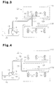
- a communication path 33 for connecting the fuel tank 15 with the first delivery pipe 12A is connected to an intermediate portion of the delivery pipe 12A (i.e., a portion located between fuel injection valves 16).
- a branch path 37 in communication with the second delivery pipe 12B and a placement channel 41 in which the pulsation damper 20 is provided are configured to branch from the branch portion of the delivery pipe 12A and the communication path 33.
- the pulsation damper 20 may be installed in any suitable manner.
- the placement channel may be eliminated, and a new extended portion, which enables the pulsation damper 20 to be provided with the introduction path 20a being opened inside the delivery pipe 12A, can be provided.
- the introduction path 20a serves as a pressure introduction path.
- Three paths, which communicate with the delivery pipes 12A and 12B and the fuel tank 15, and a placement channel may be branched from the same portion, with the pulsation damper 20 provided in the placement channel.
- An example of such configuration is illustrated in Fig. 4 .
- a branch path 57 is provided to connect to the second delivery pipe 12B after being branched from halfway on the communication path 13 that communicates between the fuel pump 14 and the first delivery pipe 12A.
- a placement channel 61 branches from the branch portion between the communication path 13 and the branch path 57.
- the pulsation damper 20 is provided in this placement channel 61.
- a return path and a pressure regulator which communicate the delivery pipes with the fuel tank may be provided.
- the number of fuel injection valves disposed on each delivery pipe may differ from one another. Only one fuel injection valve may also be disposed on each delivery pipe.
- the present invention is applicable to any type of fuel supply devices so long as they are provided with two fuel injection systems each including a delivery pipe and a fuel injection valve provided in the delivery pipe.
- the invention may be applied to not only internal combustion engines having a V-shaped cylinder arrangement but also internal combustion engines having horizontally opposing cylinder arrangements, internal combustion engines having W-shaped cylinder arrangements, or internal combustion engines having L-shaped cylinder arrangements. It is understood that those fuel supply devices including three or more fuel injection systems also fall within the scope of the present invention.
Landscapes
- Engineering & Computer Science (AREA)
- Chemical & Material Sciences (AREA)
- Combustion & Propulsion (AREA)
- Mechanical Engineering (AREA)
- General Engineering & Computer Science (AREA)
- Fuel-Injection Apparatus (AREA)
Abstract
Description
- The present invention relates to a fuel supply device for an internal combustion engine comprising two fuel injection systems, each having a delivery pipe for storing fuel and a fuel injection valve provided in the delivery pipe.
- A fuel supply device for an internal combustion engine includes delivery pipes for storing fuel that is fed under pressure by a fuel pump and supplies fuel by controlling opening of a fuel injection valve connected to each delivery pipe. In the internal combustion engine, since fuel is injected intermittently from the fuel injection valve, the pressure of the fuel is unavoidably pulsated inside the delivery pipes while the injection of the fuel is alternately executed and stopped. This pulsation of the fuel pressure would lead to various kinds of disadvantages such as occurrence of noises or degradation in efficiency of pumping fuel by the fuel pump.
- For this reason, as with a fuel supply device disclosed in Japanese Patent No.
2534493 2534493 - In the device disclosed in Japanese Patent No.
2534493 - Provision of separate pulsation dampers, one for each of the two delivery pipes, would make it possible to prevent the fuel pressure from being pulsated in each delivery pipe while preventing the interference between the pressure pulses. However, such one additional pulsation damper would undesirably add the costs of the overall device as well as results in increase in its size for installation.
- It is an object of the present invention to provide a fuel supply device for an internal combustion engine comprising one pulsation damper that can precisely suppress fuel pressure pulsations caused inside two delivery pipes.
- To address the above-mentioned problems, a fuel supply device for an internal combustion engine is provided. The device includes two fuel injection systems and a pulsation damper. Each of the two fuel injection systems has a delivery pipe for storing fuel and a fuel injection valve provided on the delivery pipe. The delivery pipe of one of the fuel injection systems is a first delivery pipe while the delivery pipe of the other fuel injection system is a second delivery pipe. The device drives intermittently the fuel injection valve to open while pumping fuel to the two fuel injection systems with a common fuel pump, thereby supplying the fuel within the first and second delivery pipes. The device further comprises a first passageway through which fuel passes, a second passageway through which fuel passes, and a pressure introduction path for introducing fuel pressure into the pulsation damper. The first passageway includes the first delivery pipe and a communication path for communicating the first delivery pipe with the fuel pump. The second passageway is branched at a location closer to the fuel pump than to the fuel injection valve in the first passageway and connected to the second delivery pipe. The second passageway includes the second delivery pipe and a branch path. The branch path has an opening at the branch location. An opposing portion in the first passageway to which the opening of the pressure introduction path is opposed includes part of the opening of the branch path.
- In one aspect of the present invention, the entire opening of the branch path may be included in the opposing portion.
In another aspect of the invention, the pressure introduction path may be a placement channel branched from the first passageway. The pulsation damper may include an introduction path for introducing fuel pressure therein. The introduction path may be provided in the placement channel with the introduction path being kept open inside the placement channel. - In still another aspect of the invention, a return path for returning excessive fuel inside the first and second passageways to a fuel tank may be connected to a portion of the first passageway closer to the fuel pump than to the branch location.
In yet another aspect of the invention, the internal combustion engine may have cylinders in a V-shaped arrangement. Each fuel injection system may be disposed in corresponding bank of the internal combustion engine. -
Fig. 1 is a schematic view illustrating a fuel supply device for an internal combustion engine according to an embodiment of the present invention; -
Fig. 2 is cross-sectional view illustrating a portion where a pulsation damper is provided and its surroundings; -
Fig. 3 is a schematic view illustrating another embodiment of the present invention; and -
Fig. 4 is a schematic view illustrating still another embodiment of the present invention. - Now, a preferred embodiment of a fuel supply device for an internal combustion engine of the invention will be described. The fuel supply device, according to this embodiment, is applicable to an internal combustion engine having cylinders arranged in a V-shape.
Fig. 1 is a schematic view illustrating the configuration of a fuel supply device for an internal combustion engine according to this embodiment. As illustrated inFig. 1 , adelivery pipe 12A is provided in afirst bank 11A of aninternal combustion engine 10 and adelivery pipe 12B is provided in asecond bank 11B. - The
first delivery pipe 12A is connected at its one end with acommunication path 13, which in turn communicates with afuel tank 15 via a motor-drivenfuel pump 14. Abranch path 17 is provided to thedelivery pipe 12A branch and extend from an intermediate portion of thedelivery pipe 12A, more specifically, the portion which is closer to thecommunication path 13 than a plurality offuel injection valves 16 provided on thedelivery pipe 12A. Thebranch path 17 is connected to an end of thesecond delivery pipe 12B. Thebranch path 17 allows thedelivery pipes internal combustion engine 10, the fuel is pumped by driving of thefuel pump 14 through thecommunication path 13 and thebranch path 17 and introduced into eachdelivery pipe - In this manner, the fuel supply device according to this embodiment includes, as passageways through which fuel passes, two passageway systems of a first passageway and a second passageway. The first passageway is made up of the
delivery pipe 12A and thecommunication path 13. The second passageway is made up of thedelivery pipe 12B and thebranch path 17. - A
pressure regulator 18 is disposed between thedelivery pipe 12A and thefuel pump 14 in thecommunication path 13, and thepressure regulator 18 is connected with areturn path 19. Thepressure regulator 18 is a pressure activated valve that is opened when the fuel pressure within thecommunication path 13 has exceeded a predetermined pressure. - In this embodiment, when fuel is fed under pressure to each of the
delivery pipes fuel pump 14 is returned to thefuel tank 15 through thepressure regulator 18 and thereturn path 19, so that the fuel pressure within thecommunication path 13 is maintained at desired pressure. - Furthermore, each of the
delivery pipes fuel injection valves 16. Thefuel injection valves 16 are located separately at the positions that correspond to a plurality of (in this embodiment, six) cylinders of theinternal combustion engine 10. - Each of the
fuel injection valves 16 is intermittently driven to open according to the operational status of theinternal combustion engine 10. This allows an appropriate amount of fuel to be injected through thefuel injection valves 16 to each cylinder of theinternal combustion engine 10 with the timing associated with the running condition thereof. - In this embodiment, the
delivery pipe 12A and the threefuel injection valves 16 provided on thedelivery pipe 12A serve as a first fuel injection system, while thedelivery pipe 12B and the threefuel injection valves 16 provided on thedelivery pipe 12B function as a second fuel injection system. - The fuel supply device according to this embodiment further includes a
pulsation damper 20. Thepulsation damper 20 operates to suppress the fuel pressure pulsations that would be caused inside each of thedelivery pipes fuel injection valves 16 being intermittently driven to open. - The
pulsation damper 20 of this embodiment positively serves to suppress fuel pressure pulsations that occur separately in each of thedelivery pipes
Now, description will be presented in detail to the placement of thepulsation damper 20 and its operation resulting from such placement. -
Fig. 2 is a cross-sectional view of the portion where thepulsation damper 20 is provided and its surroundings. As illustrated inFig. 2 , aplacement channel 21 is provided in thedelivery pipe 12A. Theplacement channel 21 is formed to branch from thedelivery pipe 12A at the branch portion between thedelivery pipe 12A and thebranch path 17. Thepulsation damper 20 includes anintroduction path 20a for introducing fuel pressure therein. Thepulsation damper 20 is disposed to block theplacement channel 21 with theintroduction path 20a kept open in theplacement channel 21. In this embodiment, theplacement channel 21 serves as a pressure introduction path for introducing fuel pressure into thepulsation damper 20. - As such, in this embodiment, the
pulsation damper 20 is provided at the branch portion between thedelivery pipe 12A and thebranch path 17. More specifically, thebranch path 17 and thepulsation damper 20 are provided in a manner such that the entire opening of thebranch path 17 in thedelivery pipe 12A is contained in an opposing portion (indicated with "P" inFig. 2 ) on thedelivery pipe 12A to which the opening of theplacement channel 21 is opposed. - In more detail, the opposing portion P is the position which is located inside the
delivery pipe 12A and which is included in theplacement channel 21 provided that theplacement channel 21 is extended until it penetrates through thedelivery pipe 12A. - The
pulsation damper 20 includes adiaphragm 20b for separating thedamper 20 between the portion disposed inside theplacement channel 21 and the portion disposed outside theplacement channel 21, and aspring 20c for resiliently energizing thediaphragm 20b into theplacement channel 21. Thepulsation damper 20 is configured so that thediaphragm 20b and thespring 20c are elastically deformed to suppress the fuel pressure pulsations inside thepulsation damper 20 as well as fuel pressure pulsations inside each of thedelivery pipes - Furthermore, the
pulsation damper 20 is disposed with an O-ring 20d sandwiched between the main body of thedamper 20 and theplacement channel 21. The O-ring 20d seals against fuel leakage between thedamper 20 and theplacement channel 21. - The
pulsation damper 20 disposed in this manner allows fuel pressure pulsations occurring in the twodelivery pipes pulsation damper 20 via theplacement channel 21. - Thus, when compared to the configuration in which the
branch path 17 is connected such that the opening of thebranch path 17 is not included in the opposing portion P, it is possible to transmit each fuel pressure pulse, which has occurred separately in thedelivery pipes pulsation damper 20 while suppressing interference between the pressure pulsations. Since each pressure pulse is conveyed to the opposing portion P through each path, interference of the pressure pulses can be prevented before they reach the opposing portion P. The amplitude of the fuel pressure pulsations can be sufficiently attenuated and thus reduced using thepulsation damper 20. - Also known is a device in which, in addition to the communication path provided with the fuel pump, a return path is also provided. The return path connects the delivery pipe with the fuel tank so that excessive fuel is returned to the fuel tank through the return path. In such a device, part of the fuel pressure pulsation occurred in the delivery pipe is not conveyed to the fuel pump but conveyed to the fuel tank via the return path.
- In this embodiment, the
return path 19 for returning excessive fuel to thefuel tank 15 is connected to a portion (specifically, on the communication path 13) which is closer to thefuel pump 14 than to the opposing portion P. Thus, all the fuel pressure pulses that have occurred in thedelivery pipes fuel pump 14. This configuration tends to increase the degree of the interference of the fuel pressure pulsations having occurred in each of thedelivery pipes - Furthermore, the opposing portion P is provided closer to the
fuel pump 14 than to the threefuel injection valves 16 in thedelivery pipe 12A. That is, the opposing portion P where thepulsation damper 20 is disposed is located between all thefuel injection valves 16 provided on each of thedelivery pipes fuel pump 14. Accordingly, the fuel pressure pulsation caused by the intermittent opening operation of the fuel injection valves can be sufficiently prevented from being transmitted to thefuel pump 14. The degrading in pumping performance of thefuel pump 14 can be preferably prevented. - Furthermore, both the cross-sectional area of the
introduction path 20a in thepulsation damper 20 and the cross-sectional area of theplacement channel 21 are greater than the cross-sectional area of thedelivery pipe 12A and the cross-sectional area of thebranch path 17. That is, there is no narrowed cross-sectional area along the path from thedelivery pipe 12A into thepulsation damper 20 and along the path from thebranch path 17 into thepulsation damper 20. For this reason, when compared to the configuration where there is a narrowed cross-sectional area, the fuel pressure pulsation in thedelivery pipe 12A and the fuel pressure pulsation in thebranch path 17 are readily transmitted into thepulsation damper 20. This enables adequate suppression of these fuel pressure pulsations. - As described above, this embodiment has the following effects.
- (1) The
branch path 17 and thepulsation damper 20 are arranged so that the entire opening of thebranch path 17 in thedelivery pipe 12A is included in the portion P in thedelivery pipe 12A to which the opening of theintroduction path 20a of thepulsation damper 20 is opposed. Thus, it is possible to transmit each fuel pressure pulse having occurred separately in thedelivery pipes pulsation damper 20 while suppressing interference of the pressure pulsations. It is also possible to prevent the interference of the fuel pressure pulsations occurred in the twodelivery pipes pulsation damper 20. - (2) The
placement channel 21, which is branched at the branch portion between thedelivery pipe 12A and thebranch path 17, is provided, and thepulsation damper 20 is disposed with theintroduction path 20a of thedamper 20 opened to theplacement channel 21. Thus, it is possible to transmit each pressure pulse which has been conveyed to the opposing portion P efficiently to theplacement channel 21 and eventually into thepulsation damper 20. - (3) The
return path 19 is connected to thecommunication path 13 and serves to return an excess of fuel that has been fed from thefuel pump 14 to thefuel tank 15. Thus, it is possible to suppress pressure pulses advantageously even in a fuel supply device which tends to be seriously affected by pressure pulses. - The above embodiments may also be modified as follows.
The cross-sectional area of theintroduction path 20a of thepulsation damper 20 and the cross-sectional area of theplacement channel 21 may be smaller than the cross-sectional area of thedelivery pipe 12A and the cross-sectional area of thebranch path 17. - The
branch path 17 and thepulsation damper 20 may be arranged so that not the entire opening of thebranch path 17 in thedelivery pipe 12A but only part of it is included in the opposing portion P. Compare this arrangement with the one where thebranch path 17 and thepulsation damper 20 are disposed so that the opening of thebranch path 17 is not included in the opposing portion P, each fuel pressure pulse having occurred in each of thedelivery pipes pulsation damper 20 while suppressing the interference of the fuel pressure pulses in this arrangement advantageously. Accordingly, this arrangement also allows onepulsation damper 20 to sufficiently attenuate and suppress the amplitude of those fuel pressure pulses. - As long as a part of the opening of the branch path is included in the opposing portion, it is possible to arbitrarily modify the connection point between the first delivery pipe and the communication path as well as the connection point between the first delivery pipe and the branch path. An example of such an arrangement is illustrated in
Fig. 3 . In the example illustrated inFig. 3 , acommunication path 33 for connecting thefuel tank 15 with thefirst delivery pipe 12A is connected to an intermediate portion of thedelivery pipe 12A (i.e., a portion located between fuel injection valves 16). Furthermore, abranch path 37 in communication with thesecond delivery pipe 12B and a placement channel 41 in which thepulsation damper 20 is provided are configured to branch from the branch portion of thedelivery pipe 12A and thecommunication path 33. - As long as the
pulsation damper 20 is configured to be installed at the branch portion between thedelivery pipe 12A and the branch path, thepulsation damper 20 may be installed in any suitable manner. For example, the placement channel may be eliminated, and a new extended portion, which enables thepulsation damper 20 to be provided with theintroduction path 20a being opened inside thedelivery pipe 12A, can be provided. In this case, theintroduction path 20a serves as a pressure introduction path. - Three paths, which communicate with the
delivery pipes fuel tank 15, and a placement channel may be branched from the same portion, with thepulsation damper 20 provided in the placement channel. An example of such configuration is illustrated inFig. 4 . In the example illustrated inFig. 4 , abranch path 57 is provided to connect to thesecond delivery pipe 12B after being branched from halfway on thecommunication path 13 that communicates between thefuel pump 14 and thefirst delivery pipe 12A. Furthermore, aplacement channel 61 branches from the branch portion between thecommunication path 13 and thebranch path 57. Thepulsation damper 20 is provided in thisplacement channel 61. - Instead of the pressure regulator provided halfway on the communication path as well as the return path extending from the pressure regulator, a return path and a pressure regulator which communicate the delivery pipes with the fuel tank may be provided.
- The number of fuel injection valves disposed on each delivery pipe may differ from one another. Only one fuel injection valve may also be disposed on each delivery pipe.
- The present invention is applicable to any type of fuel supply devices so long as they are provided with two fuel injection systems each including a delivery pipe and a fuel injection valve provided in the delivery pipe. For example, the invention may be applied to not only internal combustion engines having a V-shaped cylinder arrangement but also internal combustion engines having horizontally opposing cylinder arrangements, internal combustion engines having W-shaped cylinder arrangements, or internal combustion engines having L-shaped cylinder arrangements. It is understood that those fuel supply devices including three or more fuel injection systems also fall within the scope of the present invention.
Claims (5)
- A fuel supply device for an internal combustion engine, the fuel supply device including two fuel injection systems and a pulsation damper, each of the two fuel injection systems having a delivery pipe for storing fuel and a fuel injection valve provided in the delivery pipe, the delivery pipe of one fuel injection system being a first delivery pipe, the delivery pipe of the other fuel injection system being a second delivery pipe, wherein the device drives intermittently the fuel injection valve to open while pumping fuel to the two fuel injection systems with a common fuel pump, thereby supplying the fuel within the first and second delivery pipes, the device being characterized in that the device further comprises
a first passageway through which fuel passes, wherein the first passageway includes the first delivery pipe and a communication path for communicating the first delivery pipe with the fuel pump,
a second passageway through which fuel passes, wherein the second passageway is branched at a location closer to the fuel pump than to the fuel injection valve in the first passageway and connected to the second delivery pipe, wherein the second passageway includes the second delivery pipe and a branch path, wherein the branch path has an opening at the branch location, and
a pressure introduction path for introducing fuel pressure into the pulsation damper, wherein the pressure introduction path has an opening,
wherein an opposing portion in the first passageway to which the opening of the pressure introduction path is opposed includes part of the opening of the branch path. - The fuel supply device for an internal combustion engine according to claim 1, wherein the entire opening of the branch path is included in the opposing portion.
- The fuel supply device for an internal combustion engine according to claim 1 or 2, wherein the pressure introduction path is a placement channel branched from the first passageway, the pulsation damper includes an introduction path for introducing fuel pressure therein, and the introduction path is provided in the placement channel with the introduction path being kept open inside the placement channel.
- The fuel supply device for an internal combustion engine according to any one of claims 1 to 3, wherein a return path for returning excessive fuel inside the first and second passageways to a fuel tank is connected to a portion of the first passageway closer to the fuel pump than to the branch location.
- The fuel supply device for an internal combustion engine according to any one of claims 1 to 4, wherein the internal combustion engine has cylinders in a V-shaped arrangement, and each fuel injection system is disposed in corresponding bank of the internal combustion engine.
Applications Claiming Priority (2)
| Application Number | Priority Date | Filing Date | Title |
|---|---|---|---|
| JP2007102838A JP4462286B2 (en) | 2007-04-10 | 2007-04-10 | Fuel supply device for internal combustion engine |
| PCT/JP2008/056949 WO2008126842A1 (en) | 2007-04-10 | 2008-04-08 | Fuel supply device for internal combustion engine |
Publications (3)
| Publication Number | Publication Date |
|---|---|
| EP2136069A1 true EP2136069A1 (en) | 2009-12-23 |
| EP2136069A4 EP2136069A4 (en) | 2011-10-05 |
| EP2136069B1 EP2136069B1 (en) | 2015-11-04 |
Family
ID=39863939
Family Applications (1)
| Application Number | Title | Priority Date | Filing Date |
|---|---|---|---|
| EP08740052.9A Not-in-force EP2136069B1 (en) | 2007-04-10 | 2008-04-08 | Fuel supply device for internal combustion engine |
Country Status (5)
| Country | Link |
|---|---|
| US (1) | US7980225B2 (en) |
| EP (1) | EP2136069B1 (en) |
| JP (1) | JP4462286B2 (en) |
| CN (1) | CN101646859B (en) |
| WO (1) | WO2008126842A1 (en) |
Families Citing this family (7)
| Publication number | Priority date | Publication date | Assignee | Title |
|---|---|---|---|---|
| JP4462286B2 (en) * | 2007-04-10 | 2010-05-12 | トヨタ自動車株式会社 | Fuel supply device for internal combustion engine |
| DE102008054805B4 (en) * | 2008-12-17 | 2022-07-07 | Robert Bosch Gmbh | Fuel injection device for an internal combustion engine |
| WO2012048248A2 (en) * | 2010-10-08 | 2012-04-12 | Emissions Technology, Inc. | High volume combustion catalyst delivery system |
| JP5462855B2 (en) * | 2011-11-25 | 2014-04-02 | 本田技研工業株式会社 | Engine fuel supply system |
| JP6098344B2 (en) * | 2013-05-13 | 2017-03-22 | トヨタ自動車株式会社 | Fuel supply device for internal combustion engine |
| US10876668B2 (en) | 2018-06-13 | 2020-12-29 | Performance Pulsation Control, Inc. | Precharge manifold system and method |
| CN116950813A (en) * | 2023-07-28 | 2023-10-27 | 河南柴油机重工有限责任公司 | Fuel supply system of methanol engine |
Family Cites Families (10)
| Publication number | Priority date | Publication date | Assignee | Title |
|---|---|---|---|---|
| JP2534493B2 (en) | 1987-03-26 | 1996-09-18 | マツダ株式会社 | Fuel supply system for fuel injection engine |
| JP3292017B2 (en) | 1996-01-16 | 2002-06-17 | トヨタ自動車株式会社 | Fuel supply system for V-type engine |
| US6135092A (en) | 1997-10-29 | 2000-10-24 | General Motors Corporation | Fuel injection system |
| JP2000104636A (en) | 1998-09-25 | 2000-04-11 | Daihatsu Motor Co Ltd | Fuel supplying device for internal combustion engine |
| US6155235A (en) * | 1999-05-14 | 2000-12-05 | Siemens Automotive Corporation | Pressure pulsation damper with integrated hot soak pressure control valve |
| JP2004232472A (en) | 2003-01-28 | 2004-08-19 | Toyota Motor Corp | Failure prevention mechanism for pulsation damper in case of failure |
| JP2006105080A (en) * | 2004-10-08 | 2006-04-20 | Honda Motor Co Ltd | Returnless fuel supply system |
| DE102006003639A1 (en) * | 2006-01-26 | 2007-08-02 | Robert Bosch Gmbh | Fuel-injection system used in multicylindered internal combustion engines comprises a volume in a high-pressure reservoir for damping pressure pulses between high-pressure reservoirs and between the reservoirs and a high-pressure pump |
| JP4165572B2 (en) * | 2006-04-12 | 2008-10-15 | トヨタ自動車株式会社 | Fuel supply device for internal combustion engine |
| JP4462286B2 (en) * | 2007-04-10 | 2010-05-12 | トヨタ自動車株式会社 | Fuel supply device for internal combustion engine |
-
2007
- 2007-04-10 JP JP2007102838A patent/JP4462286B2/en not_active Expired - Fee Related
-
2008
- 2008-04-08 EP EP08740052.9A patent/EP2136069B1/en not_active Not-in-force
- 2008-04-08 US US12/521,835 patent/US7980225B2/en not_active Expired - Fee Related
- 2008-04-08 WO PCT/JP2008/056949 patent/WO2008126842A1/en not_active Ceased
- 2008-04-08 CN CN200880006636XA patent/CN101646859B/en not_active Expired - Fee Related
Also Published As
| Publication number | Publication date |
|---|---|
| CN101646859B (en) | 2011-08-10 |
| JP4462286B2 (en) | 2010-05-12 |
| US7980225B2 (en) | 2011-07-19 |
| US20100043752A1 (en) | 2010-02-25 |
| CN101646859A (en) | 2010-02-10 |
| JP2008261238A (en) | 2008-10-30 |
| EP2136069A4 (en) | 2011-10-05 |
| EP2136069B1 (en) | 2015-11-04 |
| WO2008126842A1 (en) | 2008-10-23 |
Similar Documents
| Publication | Publication Date | Title |
|---|---|---|
| EP2136069B1 (en) | Fuel supply device for internal combustion engine | |
| CN102197211B (en) | Fuel high pressure pumps for internal combustion engines | |
| US5505181A (en) | Integral pressure damper | |
| US6948480B2 (en) | Injection system with an emergency operation function and an associated emergency operation method | |
| JP4803269B2 (en) | Pulsation reduction device | |
| US6848423B2 (en) | Fuel injection system for an internal combustion engine | |
| US10041432B2 (en) | Fuel system having pump prognostic functionality | |
| JP2006207384A (en) | Fuel injection device for internal combustion engine | |
| EP2383460B1 (en) | Device for controlling variation in pressure upstream of common rail | |
| US6532938B1 (en) | Fuel injection system | |
| JP4082392B2 (en) | Fuel supply device for internal combustion engine | |
| US20190003432A1 (en) | Fuel Injection System | |
| JP3851287B2 (en) | Fuel injection device for internal combustion engine | |
| EP3015700B1 (en) | Control device for common rail fuel injection device | |
| JP5390692B2 (en) | High pressure pump | |
| EP2857672A1 (en) | Fuel injection equipment | |
| CN108779766A (en) | High pressure pump with fluid damper | |
| MX2022000008A (en) | Fuel injector having dry-running protection valve and fuel system using same. | |
| EP2799704B1 (en) | Fuel supply device | |
| JP2014224519A (en) | Fuel press-feeding control method and common rail type fuel injection control device | |
| WO2013178477A1 (en) | Fluid-Dynamic Device And Fuel Feed System Comprising Said Fluid-Dynamic Device | |
| EP3032086A1 (en) | Fuel injection arrangement | |
| CN100425816C (en) | Method for controlling discharge flow rate of accumulator fuel injection device and accumulator fuel injection device | |
| GB2548832A (en) | High pressure fuel pump arrangement | |
| EP2226491B1 (en) | Fuel-injection system for an internal-combustion engine |
Legal Events
| Date | Code | Title | Description |
|---|---|---|---|
| PUAI | Public reference made under article 153(3) epc to a published international application that has entered the european phase |
Free format text: ORIGINAL CODE: 0009012 |
|
| 17P | Request for examination filed |
Effective date: 20090629 |
|
| AK | Designated contracting states |
Kind code of ref document: A1 Designated state(s): AT BE BG CH CY CZ DE DK EE ES FI FR GB GR HR HU IE IS IT LI LT LU LV MC MT NL NO PL PT RO SE SI SK TR |
|
| DAX | Request for extension of the european patent (deleted) | ||
| A4 | Supplementary search report drawn up and despatched |
Effective date: 20110901 |
|
| RIC1 | Information provided on ipc code assigned before grant |
Ipc: F02M 37/00 20060101ALI20110826BHEP Ipc: F02M 55/02 20060101AFI20110826BHEP Ipc: F02M 55/00 20060101ALI20110826BHEP |
|
| 17Q | First examination report despatched |
Effective date: 20120405 |
|
| RAP1 | Party data changed (applicant data changed or rights of an application transferred) |
Owner name: TOYOTA JIDOSHA KABUSHIKI KAISHA |
|
| GRAP | Despatch of communication of intention to grant a patent |
Free format text: ORIGINAL CODE: EPIDOSNIGR1 |
|
| INTG | Intention to grant announced |
Effective date: 20150611 |
|
| GRAS | Grant fee paid |
Free format text: ORIGINAL CODE: EPIDOSNIGR3 |
|
| GRAA | (expected) grant |
Free format text: ORIGINAL CODE: 0009210 |
|
| AK | Designated contracting states |
Kind code of ref document: B1 Designated state(s): AT BE BG CH CY CZ DE DK EE ES FI FR GB GR HR HU IE IS IT LI LT LU LV MC MT NL NO PL PT RO SE SI SK TR |
|
| REG | Reference to a national code |
Ref country code: GB Ref legal event code: FG4D |
|
| REG | Reference to a national code |
Ref country code: CH Ref legal event code: EP |
|
| REG | Reference to a national code |
Ref country code: AT Ref legal event code: REF Ref document number: 759382 Country of ref document: AT Kind code of ref document: T Effective date: 20151115 |
|
| REG | Reference to a national code |
Ref country code: IE Ref legal event code: FG4D |
|
| REG | Reference to a national code |
Ref country code: DE Ref legal event code: R096 Ref document number: 602008040990 Country of ref document: DE |
|
| REG | Reference to a national code |
Ref country code: DE Ref legal event code: R084 Ref document number: 602008040990 Country of ref document: DE |
|
| REG | Reference to a national code |
Ref country code: NL Ref legal event code: MP Effective date: 20151104 |
|
| REG | Reference to a national code |
Ref country code: LT Ref legal event code: MG4D |
|
| REG | Reference to a national code |
Ref country code: AT Ref legal event code: MK05 Ref document number: 759382 Country of ref document: AT Kind code of ref document: T Effective date: 20151104 |
|
| PG25 | Lapsed in a contracting state [announced via postgrant information from national office to epo] |
Ref country code: NL Free format text: LAPSE BECAUSE OF FAILURE TO SUBMIT A TRANSLATION OF THE DESCRIPTION OR TO PAY THE FEE WITHIN THE PRESCRIBED TIME-LIMIT Effective date: 20151104 Ref country code: LT Free format text: LAPSE BECAUSE OF FAILURE TO SUBMIT A TRANSLATION OF THE DESCRIPTION OR TO PAY THE FEE WITHIN THE PRESCRIBED TIME-LIMIT Effective date: 20151104 Ref country code: ES Free format text: LAPSE BECAUSE OF FAILURE TO SUBMIT A TRANSLATION OF THE DESCRIPTION OR TO PAY THE FEE WITHIN THE PRESCRIBED TIME-LIMIT Effective date: 20151104 Ref country code: NO Free format text: LAPSE BECAUSE OF FAILURE TO SUBMIT A TRANSLATION OF THE DESCRIPTION OR TO PAY THE FEE WITHIN THE PRESCRIBED TIME-LIMIT Effective date: 20160204 Ref country code: IT Free format text: LAPSE BECAUSE OF FAILURE TO SUBMIT A TRANSLATION OF THE DESCRIPTION OR TO PAY THE FEE WITHIN THE PRESCRIBED TIME-LIMIT Effective date: 20151104 Ref country code: HR Free format text: LAPSE BECAUSE OF FAILURE TO SUBMIT A TRANSLATION OF THE DESCRIPTION OR TO PAY THE FEE WITHIN THE PRESCRIBED TIME-LIMIT Effective date: 20151104 Ref country code: IS Free format text: LAPSE BECAUSE OF FAILURE TO SUBMIT A TRANSLATION OF THE DESCRIPTION OR TO PAY THE FEE WITHIN THE PRESCRIBED TIME-LIMIT Effective date: 20160304 |
|
| PG25 | Lapsed in a contracting state [announced via postgrant information from national office to epo] |
Ref country code: PL Free format text: LAPSE BECAUSE OF FAILURE TO SUBMIT A TRANSLATION OF THE DESCRIPTION OR TO PAY THE FEE WITHIN THE PRESCRIBED TIME-LIMIT Effective date: 20151104 Ref country code: LV Free format text: LAPSE BECAUSE OF FAILURE TO SUBMIT A TRANSLATION OF THE DESCRIPTION OR TO PAY THE FEE WITHIN THE PRESCRIBED TIME-LIMIT Effective date: 20151104 Ref country code: FI Free format text: LAPSE BECAUSE OF FAILURE TO SUBMIT A TRANSLATION OF THE DESCRIPTION OR TO PAY THE FEE WITHIN THE PRESCRIBED TIME-LIMIT Effective date: 20151104 Ref country code: AT Free format text: LAPSE BECAUSE OF FAILURE TO SUBMIT A TRANSLATION OF THE DESCRIPTION OR TO PAY THE FEE WITHIN THE PRESCRIBED TIME-LIMIT Effective date: 20151104 Ref country code: SE Free format text: LAPSE BECAUSE OF FAILURE TO SUBMIT A TRANSLATION OF THE DESCRIPTION OR TO PAY THE FEE WITHIN THE PRESCRIBED TIME-LIMIT Effective date: 20151104 Ref country code: PT Free format text: LAPSE BECAUSE OF FAILURE TO SUBMIT A TRANSLATION OF THE DESCRIPTION OR TO PAY THE FEE WITHIN THE PRESCRIBED TIME-LIMIT Effective date: 20160304 Ref country code: GR Free format text: LAPSE BECAUSE OF FAILURE TO SUBMIT A TRANSLATION OF THE DESCRIPTION OR TO PAY THE FEE WITHIN THE PRESCRIBED TIME-LIMIT Effective date: 20160205 |
|
| PG25 | Lapsed in a contracting state [announced via postgrant information from national office to epo] |
Ref country code: CZ Free format text: LAPSE BECAUSE OF FAILURE TO SUBMIT A TRANSLATION OF THE DESCRIPTION OR TO PAY THE FEE WITHIN THE PRESCRIBED TIME-LIMIT Effective date: 20151104 |
|
| PGFP | Annual fee paid to national office [announced via postgrant information from national office to epo] |
Ref country code: DE Payment date: 20160405 Year of fee payment: 9 |
|
| REG | Reference to a national code |
Ref country code: DE Ref legal event code: R097 Ref document number: 602008040990 Country of ref document: DE |
|
| PG25 | Lapsed in a contracting state [announced via postgrant information from national office to epo] |
Ref country code: EE Free format text: LAPSE BECAUSE OF FAILURE TO SUBMIT A TRANSLATION OF THE DESCRIPTION OR TO PAY THE FEE WITHIN THE PRESCRIBED TIME-LIMIT Effective date: 20151104 Ref country code: DK Free format text: LAPSE BECAUSE OF FAILURE TO SUBMIT A TRANSLATION OF THE DESCRIPTION OR TO PAY THE FEE WITHIN THE PRESCRIBED TIME-LIMIT Effective date: 20151104 Ref country code: RO Free format text: LAPSE BECAUSE OF FAILURE TO SUBMIT A TRANSLATION OF THE DESCRIPTION OR TO PAY THE FEE WITHIN THE PRESCRIBED TIME-LIMIT Effective date: 20151104 Ref country code: SK Free format text: LAPSE BECAUSE OF FAILURE TO SUBMIT A TRANSLATION OF THE DESCRIPTION OR TO PAY THE FEE WITHIN THE PRESCRIBED TIME-LIMIT Effective date: 20151104 Ref country code: BE Free format text: LAPSE BECAUSE OF NON-PAYMENT OF DUE FEES Effective date: 20160430 |
|
| PLBE | No opposition filed within time limit |
Free format text: ORIGINAL CODE: 0009261 |
|
| STAA | Information on the status of an ep patent application or granted ep patent |
Free format text: STATUS: NO OPPOSITION FILED WITHIN TIME LIMIT |
|
| 26N | No opposition filed |
Effective date: 20160805 |
|
| PG25 | Lapsed in a contracting state [announced via postgrant information from national office to epo] |
Ref country code: SI Free format text: LAPSE BECAUSE OF FAILURE TO SUBMIT A TRANSLATION OF THE DESCRIPTION OR TO PAY THE FEE WITHIN THE PRESCRIBED TIME-LIMIT Effective date: 20151104 |
|
| REG | Reference to a national code |
Ref country code: CH Ref legal event code: PL |
|
| GBPC | Gb: european patent ceased through non-payment of renewal fee |
Effective date: 20160408 |
|
| PG25 | Lapsed in a contracting state [announced via postgrant information from national office to epo] |
Ref country code: BE Free format text: LAPSE BECAUSE OF FAILURE TO SUBMIT A TRANSLATION OF THE DESCRIPTION OR TO PAY THE FEE WITHIN THE PRESCRIBED TIME-LIMIT Effective date: 20151104 Ref country code: LU Free format text: LAPSE BECAUSE OF FAILURE TO SUBMIT A TRANSLATION OF THE DESCRIPTION OR TO PAY THE FEE WITHIN THE PRESCRIBED TIME-LIMIT Effective date: 20160408 |
|
| REG | Reference to a national code |
Ref country code: IE Ref legal event code: MM4A |
|
| REG | Reference to a national code |
Ref country code: FR Ref legal event code: ST Effective date: 20161230 |
|
| PG25 | Lapsed in a contracting state [announced via postgrant information from national office to epo] |
Ref country code: GB Free format text: LAPSE BECAUSE OF NON-PAYMENT OF DUE FEES Effective date: 20160408 Ref country code: CH Free format text: LAPSE BECAUSE OF NON-PAYMENT OF DUE FEES Effective date: 20160430 Ref country code: FR Free format text: LAPSE BECAUSE OF NON-PAYMENT OF DUE FEES Effective date: 20160502 Ref country code: LI Free format text: LAPSE BECAUSE OF NON-PAYMENT OF DUE FEES Effective date: 20160430 |
|
| PG25 | Lapsed in a contracting state [announced via postgrant information from national office to epo] |
Ref country code: IE Free format text: LAPSE BECAUSE OF NON-PAYMENT OF DUE FEES Effective date: 20160408 |
|
| REG | Reference to a national code |
Ref country code: DE Ref legal event code: R119 Ref document number: 602008040990 Country of ref document: DE |
|
| PG25 | Lapsed in a contracting state [announced via postgrant information from national office to epo] |
Ref country code: DE Free format text: LAPSE BECAUSE OF NON-PAYMENT OF DUE FEES Effective date: 20171103 |
|
| PG25 | Lapsed in a contracting state [announced via postgrant information from national office to epo] |
Ref country code: CY Free format text: LAPSE BECAUSE OF FAILURE TO SUBMIT A TRANSLATION OF THE DESCRIPTION OR TO PAY THE FEE WITHIN THE PRESCRIBED TIME-LIMIT Effective date: 20151104 Ref country code: HU Free format text: LAPSE BECAUSE OF FAILURE TO SUBMIT A TRANSLATION OF THE DESCRIPTION OR TO PAY THE FEE WITHIN THE PRESCRIBED TIME-LIMIT; INVALID AB INITIO Effective date: 20080408 |
|
| PG25 | Lapsed in a contracting state [announced via postgrant information from national office to epo] |
Ref country code: TR Free format text: LAPSE BECAUSE OF FAILURE TO SUBMIT A TRANSLATION OF THE DESCRIPTION OR TO PAY THE FEE WITHIN THE PRESCRIBED TIME-LIMIT Effective date: 20151104 Ref country code: MC Free format text: LAPSE BECAUSE OF FAILURE TO SUBMIT A TRANSLATION OF THE DESCRIPTION OR TO PAY THE FEE WITHIN THE PRESCRIBED TIME-LIMIT Effective date: 20151104 Ref country code: MT Free format text: LAPSE BECAUSE OF NON-PAYMENT OF DUE FEES Effective date: 20160430 |
|
| PG25 | Lapsed in a contracting state [announced via postgrant information from national office to epo] |
Ref country code: BG Free format text: LAPSE BECAUSE OF FAILURE TO SUBMIT A TRANSLATION OF THE DESCRIPTION OR TO PAY THE FEE WITHIN THE PRESCRIBED TIME-LIMIT Effective date: 20151104 |