EP2136061A1 - Method for determining the average angular velocity of a crankshaft of an internal combustion engine at each tooth of a phonic wheel representing the number of teeth - Google Patents
Method for determining the average angular velocity of a crankshaft of an internal combustion engine at each tooth of a phonic wheel representing the number of teeth Download PDFInfo
- Publication number
- EP2136061A1 EP2136061A1 EP09168056A EP09168056A EP2136061A1 EP 2136061 A1 EP2136061 A1 EP 2136061A1 EP 09168056 A EP09168056 A EP 09168056A EP 09168056 A EP09168056 A EP 09168056A EP 2136061 A1 EP2136061 A1 EP 2136061A1
- Authority
- EP
- European Patent Office
- Prior art keywords
- tooth
- angular
- raw
- delayed
- speed
- Prior art date
- Legal status (The legal status is an assumption and is not a legal conclusion. Google has not performed a legal analysis and makes no representation as to the accuracy of the status listed.)
- Granted
Links
Images


Classifications
-
- F—MECHANICAL ENGINEERING; LIGHTING; HEATING; WEAPONS; BLASTING
- F02—COMBUSTION ENGINES; HOT-GAS OR COMBUSTION-PRODUCT ENGINE PLANTS
- F02D—CONTROLLING COMBUSTION ENGINES
- F02D41/00—Electrical control of supply of combustible mixture or its constituents
- F02D41/02—Circuit arrangements for generating control signals
- F02D41/14—Introducing closed-loop corrections
- F02D41/1497—With detection of the mechanical response of the engine
-
- F—MECHANICAL ENGINEERING; LIGHTING; HEATING; WEAPONS; BLASTING
- F02—COMBUSTION ENGINES; HOT-GAS OR COMBUSTION-PRODUCT ENGINE PLANTS
- F02D—CONTROLLING COMBUSTION ENGINES
- F02D35/00—Controlling engines, dependent on conditions exterior or interior to engines, not otherwise provided for
- F02D35/02—Controlling engines, dependent on conditions exterior or interior to engines, not otherwise provided for on interior conditions
- F02D35/028—Controlling engines, dependent on conditions exterior or interior to engines, not otherwise provided for on interior conditions by determining the combustion timing or phasing
-
- F—MECHANICAL ENGINEERING; LIGHTING; HEATING; WEAPONS; BLASTING
- F02—COMBUSTION ENGINES; HOT-GAS OR COMBUSTION-PRODUCT ENGINE PLANTS
- F02D—CONTROLLING COMBUSTION ENGINES
- F02D41/00—Electrical control of supply of combustible mixture or its constituents
- F02D41/0097—Electrical control of supply of combustible mixture or its constituents using means for generating speed signals
-
- G—PHYSICS
- G01—MEASURING; TESTING
- G01M—TESTING STATIC OR DYNAMIC BALANCE OF MACHINES OR STRUCTURES; TESTING OF STRUCTURES OR APPARATUS, NOT OTHERWISE PROVIDED FOR
- G01M15/00—Testing of engines
- G01M15/04—Testing internal-combustion engines
- G01M15/06—Testing internal-combustion engines by monitoring positions of pistons or cranks
-
- F—MECHANICAL ENGINEERING; LIGHTING; HEATING; WEAPONS; BLASTING
- F02—COMBUSTION ENGINES; HOT-GAS OR COMBUSTION-PRODUCT ENGINE PLANTS
- F02D—CONTROLLING COMBUSTION ENGINES
- F02D41/00—Electrical control of supply of combustible mixture or its constituents
- F02D41/24—Electrical control of supply of combustible mixture or its constituents characterised by the use of digital means
- F02D41/26—Electrical control of supply of combustible mixture or its constituents characterised by the use of digital means using computer, e.g. microprocessor
- F02D41/28—Interface circuits
- F02D2041/286—Interface circuits comprising means for signal processing
- F02D2041/288—Interface circuits comprising means for signal processing for performing a transformation into the frequency domain, e.g. Fourier transformation
-
- F—MECHANICAL ENGINEERING; LIGHTING; HEATING; WEAPONS; BLASTING
- F02—COMBUSTION ENGINES; HOT-GAS OR COMBUSTION-PRODUCT ENGINE PLANTS
- F02D—CONTROLLING COMBUSTION ENGINES
- F02D2200/00—Input parameters for engine control
- F02D2200/02—Input parameters for engine control the parameters being related to the engine
- F02D2200/10—Parameters related to the engine output, e.g. engine torque or engine speed
- F02D2200/1002—Output torque
- F02D2200/1004—Estimation of the output torque
Definitions
- the present invention relates to a method for determining the average angular speed of a drive shaft of an internal combustion engine at each tooth event of a phonic wheel presenting a number of teeth.
- the MFB50 combustion index is not used as control magnitude due to the considerable difficulties in estimating such MFB50 combustion index efficiently (i.e. with sufficient accuracy), effectively (i.e. rapidly and without employing excessive calculation power) and cost-effectively (i.e. without requiring the installation of additional components with respect to those normally present).
- pressure sensors capable of directly measuring the pressure inside the cylinders are used to determine the MFB50 combustion index; however, such pressure sensors are very expensive and present a limited reliability in time and are thus only suitable for laboratory tests and not for an extensive use on standard production cars.
- US6363318B1 discloses a method to compensate errors in engine speed measurement and in particular non-fuel injection induced errors in measured engine speed. This invention provides a means to calculate a least squares regression of the measured engine speed data when the engine is motoring without combustion or load; the motoring test is to avoid the effect of unbalanced cylinder power, thus detecting only the static errors in engine speed measurements.
- numeral 1 indicates as a whole an internal combustion engine fed with oil (i.e. operating according to the Diesel cycle which contemplates the spontaneous ignition of the mixture) and mounted aboard a road vehicle (not shown) which is provided with a transmission line (not shown) for transmitting the torque generated by the internal combustion engine 1 to the ground.
- the internal combustion engine 1 comprises four cylinders 2, each of which accommodates a corresponding piston 3 mechanically connected by means of a connecting rod to a drive shaft 4 for transmitting the force generated by the combustion inside the cylinder 2 to the drive shaft 4 itself.
- a phonic wheel 5 provided with a number N (e.g. 60) of teeth 6 is keyed onto the drive shaft 4 and is coupled to a sensor 7, which is adapted to detect the time elapsed between the passage of two consecutive teeth 6.
- the teeth 6 of the phonic wheel 5 are equally spaced out except for one pair of teeth 6 which are reciprocally arranged at a greater distance than the others to constitute a singularity which allows to accurately identify each tooth 6 and thus the angular position of the phonic wheel 5 (i.e. of the drive shaft 4).
- the engine 1 further comprises a control unit 8 which is connected to the sensor 7 and is adapted to estimate, for each cylinder 2, the corresponding MFB50 (50% Mass Fraction Burnt) combustion index which represents the crank angle at which 50% of the fuel mass has been burnt inside the cylinder 2.
- MFB50 Mass Fraction Burnt
- the phonic wheel 5 is provided with a number N (e.g. 60) of teeth 6, which are equally spaced out except for one pair of teeth 6 which are reciprocally arranged at a greater distance than the others to constitute a singularity which accurately allows to identify each tooth 6; in this manner, each tooth 6 is identified by a characteristic sequential number i included between 1 and N.
- N e.g. 60
- the sensor 7 detects the number i of the current tooth 6 (i th tooth), the time T i of the current tooth 6, i.e. the interval of time elapsing between the detections of the two angular events which characterize the current tooth 6, the raw angular speed ⁇ raw,i of the current tooth 6, and the drive angle ⁇ (i.e. the angular position of the drive shaft 4 which is comprised between 0 and 4n radians).
- the magnitudes detected by sensor 7 and listed above are transmitted to a compensation block 9, which corrects each raw angular speed ⁇ raw,i to compensate for the errors deriving from the inevitable manufacturing tolerances of the teeth 6.
- a characteristic shape error i.e. presents a characteristic angular amplitude more or less different from the theoretical angular amplitude; consequently, the angular speeds ⁇ raw,i are afflicted by an intense noise which makes their use without an appropriate compensation practically impossible.
- a vector ( ⁇ 1 , ⁇ 2 ,..., ⁇ i ,..., ⁇ N ) composed of N compensation values ⁇ i , each of which is associated to a corresponding i th tooth 6 and represents the difference between the actual angular amplitude of the i th tooth 6 and the theoretic amplitude of the i th tooth 6.
- the corresponding compensated angular speed ⁇ i is calculated for each tooth 6 in the compensation block 9 by using the following equation:
- the calibration mode used to determine the compensation values ⁇ i of the teeth 6 is described below.
- the calibration mode contemplates calculating the raw angular speed ⁇ raw,i of the i th tooth 6 by using the above-described equation and calculating the average angular speed ⁇ av,i per revolution of the i th tooth 6 by means of a moving average filter on N values of the raw angular speeds ⁇ raw,i sequence; it is important to observe that the moving average filter on N values of the raw angular speeds ⁇ raw,i sequence introduces a phase delay equal to N/2 tooth intervals to the average angular speeds ⁇ av,i .
- the raw angular speeds ⁇ raw,i sequence is intentionally delayed by a phase delay equal to N/2 tooth intervals to equal the phase delay introduced by the moving average filter.
- the delayed angular errors vector ⁇ i-N/2 may be used either to determine (in the case of first absolute calibration operation) or to update the compensation values vector ⁇ i .
- a compensation value vector ⁇ i is updated, it is preferably used a weighed average between the previous compensation values ⁇ i and the corresponding delayed angular errors ⁇ i-N/2 which normally assigns a higher weight to the previous compensation values ⁇ i (e.g. higher the value as higher is the confidence in the previous compensation values ⁇ i ).
- the above-described calibration operation for determining/updating the compensation values vector ⁇ i is performed only in presence of certain circumstances, e.g. when the internal combustion engine 1 is in cut-off phase and the revolution speed of the drive shaft 4 is included in a certain calibration range so that the reciprocating, indicated inertial torques approximately are balanced with the internal combustion engine 1 in cut-off phase.
- the compensated angular speeds ⁇ i calculated by the compensation block 9 are supplied to an analysis block 10, in which a frequency analysis of the known type is performed on the compensated angular speeds ⁇ i to determine at least one speed signal harmonic ⁇ n .
- the harmonic generic ⁇ n of the n th speed signal is always a complex number, characterized by its own module
- the torque harmonic T n is a complex number characterized by its own module
- of the torque harmonics T n calculated by the calculation block 11 is supplied to a calculation block 12, in which there is implemented an algebraic function ⁇ which puts the average indicated torque T ind into relation with the module
- of the n th torque harmonic T n according to the following equation: T ind ⁇ T n , P
- the engineering parameters P of the internal combustion engine 1 comprise the revolution speed of the drive shaft 4 and the intake pressure (i.e. the pressure present inside an intake pipe).
- equations of the direct mechanical model of the transmission in the frequency domain may be the following:
- the values of the coefficients c i may be obtained experimentally by minimising the mean square error between a series of measured values of the combustion index MFB50 and a corresponding series of estimated values of the combustion index MFB50.
- the algebraic function ⁇ which puts the average indicated torque T ind into relation with the module
- of the harmonic T n of the n th torque could be as follows: T ind b 0 + b 1 Tn + b 2 ⁇ P + b 3 ⁇ N
- the values of the coefficients b i may be obtained experimentally by minimising the mean square error between a series of measured values of the average indicated torque T ind and a corresponding series of estimated values of the average indicated torque T ind .
- the above-described estimation mode of the combustion index MFB50 in each cylinder 2 presents many advantages, because it is efficient (i.e. it allows to estimate the combustion index MFB50 with a considerable accuracy), effective (i.e. it allows to estimate the combustion index MFB50 rapidly and without employing excessive calculation power), and cost-effective (i.e. it does not require the installation of additional components with respect to those normally present in a modern internal combustion engine operating according to the "Diesel" cycle).
- the combustion index MFB50 in each cylinder 2 may be advantageously used to govern the force on the connecting rods and knock phenomena.
- the above-described estimation mode of the combustion index MFB50 in each cylinder 2 allows to obtain the average indicated torque T ind produced by each cylinder 2 which may be effectively used to further improve the combustion process control.
Landscapes
- Engineering & Computer Science (AREA)
- Chemical & Material Sciences (AREA)
- Combustion & Propulsion (AREA)
- Mechanical Engineering (AREA)
- General Engineering & Computer Science (AREA)
- Physics & Mathematics (AREA)
- General Physics & Mathematics (AREA)
- Combined Controls Of Internal Combustion Engines (AREA)
- Electrical Control Of Air Or Fuel Supplied To Internal-Combustion Engine (AREA)
- Electrical Control Of Ignition Timing (AREA)
- Testing Of Engines (AREA)
Abstract
Description
- The present invention relates to a method for determining the average angular speed of a drive shaft of an internal combustion engine at each tooth event of a phonic wheel presenting a number of teeth.
- In internal combustion engines with controlled mixture ignition (i.e. in internal combustion engines operating according to the "Otto" cycle and fed with gasoline, methane, LPG or the like) it has been known for many years to use as control magnitude the MFB50 (50% Mass Fraction Burnt) combustion index which represents the crank angle at which 50% of the fuel mass has been burnt inside a cylinder. Indeed, in an internal combustion engine with controlled mixture ignition, the starting instant of combustion (i.e. the sparking instant of the ignition spark) is certainly and accurately known and is chosen beforehand by the engine control strategy by means of the spark advance control.
- Instead, in internal combustion engines with spontaneous mixture ignition (i.e. in internal combustion engines operating according to the "Diesel" cycle and fed with oil or similar) the MFB50 combustion index is not used as control magnitude due to the considerable difficulties in estimating such MFB50 combustion index efficiently (i.e. with sufficient accuracy), effectively (i.e. rapidly and without employing excessive calculation power) and cost-effectively (i.e. without requiring the installation of additional components with respect to those normally present).
- Currently, pressure sensors capable of directly measuring the pressure inside the cylinders are used to determine the MFB50 combustion index; however, such pressure sensors are very expensive and present a limited reliability in time and are thus only suitable for laboratory tests and not for an extensive use on standard production cars.
-
US6363318B1 discloses a method to compensate errors in engine speed measurement and in particular non-fuel injection induced errors in measured engine speed. This invention provides a means to calculate a least squares regression of the measured engine speed data when the engine is motoring without combustion or load; the motoring test is to avoid the effect of unbalanced cylinder power, thus detecting only the static errors in engine speed measurements. - It is the object of the present invention to provide a method for effectively, efficiently and cost-effectively determining the average angular speed of a drive shaft of an internal combustion engine at each tooth event of a phonic wheel presenting a number of teeth.
- According to the present invention, there is provided a method for determining the average angular speed of a drive shaft of an internal combustion engine at each tooth event of a phonic wheel presenting a number of teeth as claimed in the accompanying claims.
- The present invention will now be described with reference to the accompanying drawings which illustrate a non-limitative embodiment thereof, in which:
-
figure 1 is a diagrammatic view of an internal combustion engine provided with a control unit which implements the method for determining the average angular speed of a drive shaft objective of the present invention, and -
figure 2 is a block chart which illustrates the operation of the control unit infigure 1 for estimating the MFB50 combustion index. - In
figure 1 , numeral 1 indicates as a whole an internal combustion engine fed with oil (i.e. operating according to the Diesel cycle which contemplates the spontaneous ignition of the mixture) and mounted aboard a road vehicle (not shown) which is provided with a transmission line (not shown) for transmitting the torque generated by the internal combustion engine 1 to the ground. The internal combustion engine 1 comprises four cylinders 2, each of which accommodates a corresponding piston 3 mechanically connected by means of a connecting rod to adrive shaft 4 for transmitting the force generated by the combustion inside the cylinder 2 to thedrive shaft 4 itself. - A
phonic wheel 5 provided with a number N (e.g. 60) of teeth 6 is keyed onto thedrive shaft 4 and is coupled to asensor 7, which is adapted to detect the time elapsed between the passage of two consecutive teeth 6. The teeth 6 of thephonic wheel 5 are equally spaced out except for one pair of teeth 6 which are reciprocally arranged at a greater distance than the others to constitute a singularity which allows to accurately identify each tooth 6 and thus the angular position of the phonic wheel 5 (i.e. of the drive shaft 4). The engine 1 further comprises acontrol unit 8 which is connected to thesensor 7 and is adapted to estimate, for each cylinder 2, the corresponding MFB50 (50% Mass Fraction Burnt) combustion index which represents the crank angle at which 50% of the fuel mass has been burnt inside the cylinder 2. - With reference to
figure 2 , there is described the mode used by thecontrol unit 8 to estimate the MFB50 combustion index in each cylinder 2 by using the information provided by thesensor 7 coupled to thephonic wheel 5. - As previously mentioned, the
phonic wheel 5 is provided with a number N (e.g. 60) of teeth 6, which are equally spaced out except for one pair of teeth 6 which are reciprocally arranged at a greater distance than the others to constitute a singularity which accurately allows to identify each tooth 6; in this manner, each tooth 6 is identified by a characteristic sequential number i included between 1 and N. - The
sensor 7 detects the number i of the current tooth 6 (ith tooth), the time Ti of the current tooth 6, i.e. the interval of time elapsing between the detections of the two angular events which characterize the current tooth 6, the raw angular speed ωraw,i of the current tooth 6, and the drive angle α (i.e. the angular position of thedrive shaft 4 which is comprised between 0 and 4n radians). The raw angular speed ωraw,i of the ith tooth 6 is supplied by the following equation:
- ωi,raw
- raw angular speed of the ith tooth 6 [rad/s];
- Δαi
- angular amplitude of the ith tooth 6 [rad];
- Ti
- time of the ith tooth 6 [s].
- The magnitudes detected by
sensor 7 and listed above are transmitted to acompensation block 9, which corrects each raw angular speed ωraw,i to compensate for the errors deriving from the inevitable manufacturing tolerances of the teeth 6. In principle, all teeth 6 have the same angular amplitude, but actually due to the inevitable manufacturing tolerances each tooth 6 presents a characteristic shape error, i.e. presents a characteristic angular amplitude more or less different from the theoretical angular amplitude; consequently, the angular speeds ωraw,i are afflicted by an intense noise which makes their use without an appropriate compensation practically impossible. In order to compensate for the shape errors of teeth 6, there is stored a vector (δµ1, δµ2,...,δµi,...,δµN) composed of N compensation values δµi, each of which is associated to a corresponding ith tooth 6 and represents the difference between the actual angular amplitude of the ith tooth 6 and the theoretic amplitude of the ith tooth 6. - The corresponding compensated angular speed ωi is calculated for each tooth 6 in the
compensation block 9 by using the following equation: - ωi =
- (Δαi + δµi) / Ti
- ωi
- compensated angular speed of the ith tooth 6 [rad/s];
- Δαi
- angular amplitude of the ith tooth 6 [rad];
- δµi
- compensation value δµi of the ith tooth 6 [rad];
- Ti
- time of the ith tooth 6 [s].
- The calibration mode used to determine the compensation values δµi of the teeth 6 is described below. The calibration mode contemplates calculating the raw angular speed ωraw,i of the ith tooth 6 by using the above-described equation and calculating the average angular speed ωav,i per revolution of the ith tooth 6 by means of a moving average filter on N values of the raw angular speeds ωraw,i sequence; it is important to observe that the moving average filter on N values of the raw angular speeds ωraw,i sequence introduces a phase delay equal to N/2 tooth intervals to the average angular speeds ωav,i. Subsequently, the delayed speed error Δωi-N/2 is calculated for the ith tooth 6 by using the following equation:

- Δωi-N/2
- delayed speed error of the i-N/2thtooth 6 [rad/s];
- ωav,i
- average angular speed per revolution of ith tooth 6 [rad/s] presenting a phase delay equal to N/2 tooth intervals;
- ωraw,i-N/2
- raw angular speed ωraw,i of the i-N/2th tooth 6 [rad/s].
- The raw angular speeds ωraw,i sequence is intentionally delayed by a phase delay equal to N/2 tooth intervals to equal the phase delay introduced by the moving average filter.
- Subsequently, the delayed angular error δαi-N/2 for the ith tooth 6 is determined by using the following equation:

- δαi-N/2
- delayed angular error of the i-N/2th tooth 6 [rad];
- Δωi-N/2
- delayed angular speed of the i-N/2th tooth 6 [rad/s];
- Ti-N/2
- time of the i-N/2th tooth 6 [s].
- Finally, the delayed angular errors vector δαi-N/2 may be used either to determine (in the case of first absolute calibration operation) or to update the compensation values vector δµi. According to a preferred embodiment, before actually using a delayed angular errors vector δαi-N/2, it is checked that each delayed angular error δαi-N/2 of the vector itself is lower as absolute value than an acceptability threshold which indicates the maximum possible tolerance to the shape of the teeth 6; only if each delayed angular error δαi-N/2 of the vector is lower as absolute value than the acceptability threshold may the delayed angular errors vector δαi-N/2 actually be used. If a compensation value vector δµi is updated, it is preferably used a weighed average between the previous compensation values δµi and the corresponding delayed angular errors δαi-N/2 which normally assigns a higher weight to the previous compensation values δµi (e.g. higher the value as higher is the confidence in the previous compensation values δµi). For example, the following equation could be used:

- δµi,j
- updated ith compensation value [rad];
- k
- non-dimensional weight included between 0 and 1;
- δαi
- ith angular error [rad];
- δαi,j-1
- previous i-1th compensation value [rad].
- Preferably, the above-described calibration operation for determining/updating the compensation values vector δµi is performed only in presence of certain circumstances, e.g. when the internal combustion engine 1 is in cut-off phase and the revolution speed of the
drive shaft 4 is included in a certain calibration range so that the reciprocating, indicated inertial torques approximately are balanced with the internal combustion engine 1 in cut-off phase. - The compensated angular speeds ωi calculated by the
compensation block 9 are supplied to ananalysis block 10, in which a frequency analysis of the known type is performed on the compensated angular speeds ωi to determine at least one speed signal harmonic Ωn. The harmonic generic Ωn of the nth speed signal is always a complex number, characterized by its own module |Ωn| and its own phase Arg (Ωn). - The harmonics Ωn of the speed signal calculated by the
analysis block 10 are supplied to acalculation block 11, in which there is implemented an algorithm based on an inverse mechanical model of the transmission which is symbolically indicated by the equation H(jω) = T / Ω and represents, in the ω frequency domain, the relation between the Fourier transforms of the angular speed Ω and of the torque T of the internal combustion engine 1. The function H(jω) is a complex value function and allows to obtain the nth torque harmonic Tn by means of the equation:
- Tn nth
- torque harmonic;
- Ωn nth
- speed signal harmonic.
- As the speed signal harmonic Ωn, the torque harmonic Tn is a complex number characterized by its own module |Tn| and by its own phase Arg(Tn). It is important to observe that in order to be able to obtain precise estimations, the inverse mechanical model of the transmission must consider the inertial torques caused by the masses in reciprocating motion (e.g. the masses of the pistons 3).
- The module |Tn| of the torque harmonics Tn calculated by the
calculation block 11 is supplied to acalculation block 12, in which there is implemented an algebraic function Γ which puts the average indicated torque Tind into relation with the module |Tn| of the nth torque harmonic Tn according to the following equation:
- Tind
- average indicated torque Tind;
- |Tn| I
- nth torque harmonic module Tn;
- P
- set of engineering parameters of the internal combustion engine 1.
- Normally, the engineering parameters P of the internal combustion engine 1 comprise the revolution speed of the
drive shaft 4 and the intake pressure (i.e. the pressure present inside an intake pipe). - The phase Arg(Tn) of the torque harmonics Tn calculated by the
calculation block 11 is supplied to acalculation block 13, in which there is implemented an algebraic function Ψ which puts the MFB50 combustion index into relation with the phase Arg(Tn) of the nth torque harmonic Tn according to the following equation:
- MFB50
- MFB50 combustion index;
- Arg(Tn)
- phase of the nth torque harmonic Tn;
- P
- set of engineering parameters of the internal combustion engine 1.
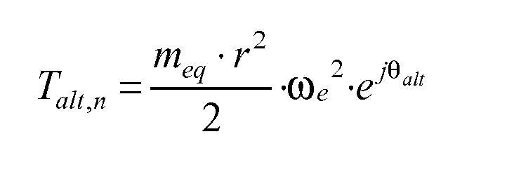
- By way of non-binding example, the equations of the direct mechanical model of the transmission in the frequency domain may be the following:
- Torque engine side


- Inertial torque
- Cylinder torque

- J1
- moment of inertia of the internal combustion engine 1;
- J2
- moment of inertia of the vehicle referred to the
drive shaft 4; - Keb
- stiffness of the transmission line;
- ρeb
- damping coefficient of the transmission line;
- j
- imaginary unit;
- n
- harmonic order;
- ωe
- pulse;
- ωe
- angular speed of the
drive shaft 4;Te torque generated by the internal combustion engine 1; - Talt,n
- torque due to the reciprocating motion masses;
- meq
- reciprocating motion masses;
- θalt
- inertial torque phase factor (reciprocating motion);
- Tind
- average indicated torque.
- The inverse mechanical model of the transmission (previously symbolically indicated by the equation H(jώ) = T / Ω) is obtained from the three equations of the direct mechanical model of the transmission shown above by replacing the first and the second equation in the third equation and so as to put the average indicated torque Tind,n into relation with the angular speed ωe,n of the
drive shaft 4; the relation between the average indicated torque Tind,n and the angular speed ωe,n of thedrive shaft 4 supplies the inverse mechanical model of the transmission (the final formula of the inverse mechanical model of the transmission is not shown because it does not add information and is complex to annotate). It is important to observe that in practice an experimental methodology is performed to experimentally obtain by points the transfer function of the inverse mechanical model of the transmission. - By way of non-binding example, the algebraic function Ψ which puts the combustion index MFB50 into relation with the phase Arg(Tn) of the harmonic Tn of the nth torque could be as follows:

- MFB50
- combustion index;
- Φ
- phase of the nth torque harmonic Tn;
- P
- intake pressure;
- ci
- coefficients.
- The values of the coefficients ci may be obtained experimentally by minimising the mean square error between a series of measured values of the combustion index MFB50 and a corresponding series of estimated values of the combustion index MFB50.
- By way of non-binding example, the algebraic function Γ which puts the average indicated torque Tind into relation with the module |Tn| of the harmonic Tn of the nth torque could be as follows:

- Tind
- average indicated torque Tind;
- |Tn|
- nth torque harmonic module Tn;
- P
- intake pressure;
- N
- revolution speed of the
drive shaft 4; - bi
- coefficients.
- The values of the coefficients bi may be obtained experimentally by minimising the mean square error between a series of measured values of the average indicated torque Tind and a corresponding series of estimated values of the average indicated torque Tind.
- The above-described estimation mode of the combustion index MFB50 in each cylinder 2 presents many advantages, because it is efficient (i.e. it allows to estimate the combustion index MFB50 with a considerable accuracy), effective (i.e. it allows to estimate the combustion index MFB50 rapidly and without employing excessive calculation power), and cost-effective (i.e. it does not require the installation of additional components with respect to those normally present in a modern internal combustion engine operating according to the "Diesel" cycle).
- In virtue of the possibility of estimating the combustion index MFB50 in each cylinder 2, it is possible to feedback control the combustion process in virtue of which it is possible to reduce the fuel consumption and the polluting emissions, the performances being equal. For example, the combustion index MFB50 in each cylinder 2 may be advantageously used to govern the force on the connecting rods and knock phenomena.
- Furthermore, the above-described estimation mode of the combustion index MFB50 in each cylinder 2 allows to obtain the average indicated torque Tind produced by each cylinder 2 which may be effectively used to further improve the combustion process control.
Claims (6)
- A method for determining the average angular speed (ωi) of a drive shaft (4) of an internal combustion engine (1) at each tooth event of a phonic wheel (5) presenting a number N of teeth (6); the method comprises the steps of:detecting the angular amplitude (Δαi) for each tooth 6;detecting the time (Ti) of each tooth (6) ;determining the raw angular speed (ωraw,i) of each tooth (6) according to the corresponding angular amplitude (Δαi) and time (Ti) ;determining for each tooth (6) a compensation value (δµi) which represents the difference between the actual angular amplitude of the tooth (6) and the theoretic angular amplitude of the tooth (6); anddetermining the average angular speed (ωi) of each tooth (6) by correcting the raw angular speed (ωraw,i) by means of the corresponding compensation value (δµi) ;the method is characterized in that the step of determining the compensation value (δµi) for each tooth (6) comprises the further steps of:calculating the raw angular speed (ωraw,i) of the tooth (6);calculating an average angular speed (ωav,i) per revolution of the tooth (6) by means of a moving average filter on N values of the raw angular speeds sequence (ωraw,i) ;calculating a delayed speed error (Δωi-N/2) of the tooth (6) as difference between the average angular speed (ωav,i) per revolution and the delayed raw angular speed (ωraw,i) of one phase delay equal to N/2 tooth intervals;determining a delayed angular error (δαi-N/2) of the tooth (6) by multiplying the delayed speed error (Δωi-N/2) of the tooth (6) by the time (Ti) of the tooth (6) delayed by a phase delay equal to N/2 tooth intervals; andusing the delayed angular error (δαi-N/2) for either determining or updating the compensation value (δµi) of the tooth (6).
- A method according to claim 1, wherein the average angular speed (ωi) of each tooth (6) is determined according to the following equation:
 ωi average compensated angular speed of the ith tooth (6) [rad/s];Δαi angular amplitude of the ith tooth (6) [rad];δµi compensation value δµi of the ith tooth (6) [rad];Ti time of the ith tooth (6) [s].
 - A method according to claim 1 or 2, wherein the delayed speed error (Δωi-N/2) of the tooth (6) is calculated by using the following equation:
 Δωi-N/2 delayed speed error of the i-N/2th tooth (6) [rad/s];ωav,i average angular speed per revolution of ith tooth (6) [rad/s] presenting a phase delay equal to N/2 tooth intervals;ωraw,i-N/2 raw angular speed ωraw,i of the i-N/2th tooth (6) [rad/s].
 - A method according to claim 3, wherein the delayed angular error (δαi-N/2) of the tooth (6) is calculated by using the following equation:
 δαi-N/2 delayed angular error of the i-N/2th tooth (6) [rad];Δωi-N/2 delayed speed error of the i-N/2th tooth (6) [rad/s];Ti-N/(2) time of the i-N/2th tooth 6 [s].
 - A method according to claim 3 or 4, wherein a vector of N delayed angular errors (δαi-N/2) is used to either determine or update a compensation values vector (δµi) only if each delayed angular error (δαi-N/2) of the vector itself is lower as absolute value than an acceptability threshold which indicates the maximum possible tolerance on the shape of the tooth (6).
- A method according to one of the claims from 1 to 5, wherein the compensation values (δµi) of the teeth (6) are either determined or updated only when the internal combustion engine (1) is in cut-off phase and the revolution speed of the drive shaft (4) is comprised in a certain calibration range so that the reciprocating, indicated inertial torques are approximately balanced with the internal combustion engine (1) in cut-off phase.
Priority Applications (1)
| Application Number | Priority Date | Filing Date | Title |
|---|---|---|---|
| DE602007009330T DE602007009330D1 (en) | 2007-07-25 | 2007-07-25 | Method for determining the average speed of the crankshaft of an internal combustion engine |
Applications Claiming Priority (1)
| Application Number | Priority Date | Filing Date | Title |
|---|---|---|---|
| EP07425457A EP2022967B1 (en) | 2007-07-25 | 2007-07-25 | Method for estimating the crank angle at which the 50% mass fraction burn time occurs in an internal combustion engine |
Related Parent Applications (2)
| Application Number | Title | Priority Date | Filing Date |
|---|---|---|---|
| EP07425457.4 Division | 2007-07-25 | ||
| EP07425457A Division EP2022967B1 (en) | 2007-07-25 | 2007-07-25 | Method for estimating the crank angle at which the 50% mass fraction burn time occurs in an internal combustion engine |
Publications (3)
| Publication Number | Publication Date |
|---|---|
| EP2136061A1 true EP2136061A1 (en) | 2009-12-23 |
| EP2136061A9 EP2136061A9 (en) | 2010-05-12 |
| EP2136061B1 EP2136061B1 (en) | 2010-09-15 |
Family
ID=38894116
Family Applications (2)
| Application Number | Title | Priority Date | Filing Date |
|---|---|---|---|
| EP09168056A Active EP2136061B1 (en) | 2007-07-25 | 2007-07-25 | Method for determining the average rotational speed of a crankshaft in an internal combustion engine |
| EP07425457A Active EP2022967B1 (en) | 2007-07-25 | 2007-07-25 | Method for estimating the crank angle at which the 50% mass fraction burn time occurs in an internal combustion engine |
Family Applications After (1)
| Application Number | Title | Priority Date | Filing Date |
|---|---|---|---|
| EP07425457A Active EP2022967B1 (en) | 2007-07-25 | 2007-07-25 | Method for estimating the crank angle at which the 50% mass fraction burn time occurs in an internal combustion engine |
Country Status (6)
| Country | Link |
|---|---|
| US (2) | US7827857B2 (en) |
| EP (2) | EP2136061B1 (en) |
| CN (2) | CN103147867B (en) |
| AT (2) | ATE481561T1 (en) |
| BR (2) | BR122018074529B1 (en) |
| DE (2) | DE602007009330D1 (en) |
Cited By (3)
| Publication number | Priority date | Publication date | Assignee | Title |
|---|---|---|---|---|
| US20130173210A1 (en) * | 2011-12-29 | 2013-07-04 | Matthias Cwik | Method for determining an average rotational speed of a rotating transmission shaft of an internal combustion engine |
| US10845220B2 (en) * | 2015-07-15 | 2020-11-24 | Samsung Electronics Co., Ltd. | Method of sensing rotation of rotation member and electronic device performing same |
| US11585682B2 (en) * | 2018-09-24 | 2023-02-21 | Vitesco Technologies GmbH | Method for determining the position of a motor vehicle crankshaft |
Families Citing this family (12)
| Publication number | Priority date | Publication date | Assignee | Title |
|---|---|---|---|---|
| ITBO20100562A1 (en) * | 2010-09-16 | 2012-03-17 | Magneti Marelli Spa | ESTIMATION METHOD OF A COMBUSTION AND / OR TORQUE INDEX INDICATED IN A CYLINDER OF AN INTERNAL COMBUSTION ENGINE |
| KR101189486B1 (en) * | 2010-09-30 | 2012-10-12 | 한양대학교 산학협력단 | Combustion detecting method of engine |
| ITBO20120023A1 (en) * | 2012-01-19 | 2013-07-20 | Magneti Marelli Spa | ESTIMATE METHOD OF TORQUE UNBALANCE INDICATED PROVIDED BY THE CYLINDERS OF AN INTERNAL COMBUSTION ENGINE |
| CN105283768A (en) | 2013-06-12 | 2016-01-27 | 瓦锡兰芬兰有限公司 | Determination of angular speed in an engine |
| ITUB20154998A1 (en) | 2015-11-03 | 2017-05-03 | Magneti Marelli Spa | ESTIMATION METHOD OF THE MFB50 COMBUSTION INDEX AND INSTANTANEOUS TORQUE GENERATED BY THE CYLINDERS OF AN INTERNAL COMBUSTION ENGINE |
| GB2555436B (en) * | 2016-10-27 | 2019-05-08 | Delphi Tech Ip Ltd | Method to determine tooth error in period of one or more teeth of a rotating toothed wheel |
| DE102019207252B4 (en) * | 2018-11-14 | 2024-09-12 | Vitesco Technologies GmbH | Recording of cylinder-specific combustion process parameter values for an internal combustion engine |
| CN109630289B (en) * | 2018-12-13 | 2020-07-07 | 清华大学 | Engine instantaneous torque estimation method for reconstructing in-cylinder pressure based on combustion model |
| CN109991438B (en) * | 2019-03-26 | 2021-12-07 | 武汉理工大学 | Method and device for eliminating angular speed measurement error of automobile gear ring |
| FR3129983B1 (en) | 2021-12-08 | 2023-10-27 | Vitesco Technologies | motor control method and device |
| IT202200013879A1 (en) | 2022-06-30 | 2023-12-30 | Marelli Europe Spa | METHOD FOR ESTIMATING THE MAXIMUM PRESSURE INSIDE A COMBUSTION CHAMBER OF A CYLINDER OF AN INTERNAL COMBUSTION ENGINE |
| CN115935840B (en) * | 2022-12-02 | 2023-08-11 | 哈尔滨工程大学 | A Cylinder Pressure Reconstruction Method Based on Reversed Cylinder Pressure and Torque Signals |
Citations (3)
| Publication number | Priority date | Publication date | Assignee | Title |
|---|---|---|---|---|
| US6363318B1 (en) | 2000-06-21 | 2002-03-26 | Cummins Engine Company, Inc. | Method to compensate errors in engine speed measurement |
| DE102004048133A1 (en) * | 2004-10-02 | 2006-04-06 | Robert Bosch Gmbh | Method of measuring the speed of a crankshaft |
| US20070144487A1 (en) * | 2005-12-26 | 2007-06-28 | Denso Corporation | Control system and timing rotor for multi-cylinder internal combustion engine |
Family Cites Families (13)
| Publication number | Priority date | Publication date | Assignee | Title |
|---|---|---|---|---|
| DE3122376A1 (en) * | 1981-06-05 | 1982-12-23 | Robert Bosch Gmbh, 7000 Stuttgart | DEVICE FOR DETECTING THE SPEED OF ROTATING PARTS |
| US5200899A (en) * | 1990-04-20 | 1993-04-06 | Regents Of The University Of Michigan | Method and system for detecting the misfire of an internal combustion engine utilizing angular velocity fluctuations |
| US6142026A (en) * | 1994-06-06 | 2000-11-07 | Toyota Jidosha Kabushiki Kaisha | Wheel information estimating apparatus |
| DE19540674C2 (en) * | 1995-10-31 | 1999-01-28 | Siemens Ag | Adaptation procedure for correcting tolerances of an encoder wheel |
| US5977765A (en) * | 1997-12-05 | 1999-11-02 | Ford Global Technologies, Inc. | Speed, direction, and acceleration sensor for a rotating shaft having a rotor with teeth having unequal spacing |
| FR2793558B1 (en) * | 1999-05-10 | 2001-07-06 | Renault | METHOD AND DEVICE FOR MEASURING THE TORQUE OF AN INTERNAL COMBUSTION ENGINE |
| US6866024B2 (en) * | 2001-03-05 | 2005-03-15 | The Ohio State University | Engine control using torque estimation |
| US6752009B2 (en) * | 2001-08-03 | 2004-06-22 | General Motors Corporation | Encoded crank position sensor |
| EP1470325B1 (en) * | 2002-01-24 | 2007-10-24 | Fraunhofer-Gesellschaft zur Förderung der angewandten Forschung e.V. | Method for determining and compensating the geometric errors of a rotary encoder |
| ITBO20030529A1 (en) * | 2003-09-15 | 2005-03-16 | Magneti Marelli Powertrain Spa | METHOD TO DETECT THE ANGULAR ACCELERATION OF ONE |
| FI121150B (en) * | 2005-11-30 | 2010-07-30 | Waertsilae Finland Oy | Apparatus and method for a piston combustion engine for identifying an uneven cylinder power ratio |
| US7400993B2 (en) * | 2006-10-31 | 2008-07-15 | General Electric Company | Method and system for accuracy of speed and acceleration measurements on rotating machinery with a speed wheel |
| US7814780B2 (en) * | 2007-04-09 | 2010-10-19 | Bg Soflex Llc | Engine position tracking for internal combustion engines |
-
2007
- 2007-07-25 EP EP09168056A patent/EP2136061B1/en active Active
- 2007-07-25 AT AT09168056T patent/ATE481561T1/en not_active IP Right Cessation
- 2007-07-25 AT AT07425457T patent/ATE483103T1/en not_active IP Right Cessation
- 2007-07-25 DE DE602007009330T patent/DE602007009330D1/en active Active
- 2007-07-25 DE DE602007009520T patent/DE602007009520D1/en active Active
- 2007-07-25 EP EP07425457A patent/EP2022967B1/en active Active
-
2008
- 2008-07-23 US US12/177,922 patent/US7827857B2/en active Active
- 2008-07-24 BR BR122018074529-0A patent/BR122018074529B1/en not_active IP Right Cessation
- 2008-07-24 BR BRPI0803875-9A patent/BRPI0803875B1/en active IP Right Grant
- 2008-07-25 CN CN201210393607.1A patent/CN103147867B/en active Active
- 2008-07-25 CN CN200810134756XA patent/CN101408140B/en active Active
-
2010
- 2010-10-05 US US12/897,968 patent/US8028568B2/en active Active
Patent Citations (3)
| Publication number | Priority date | Publication date | Assignee | Title |
|---|---|---|---|---|
| US6363318B1 (en) | 2000-06-21 | 2002-03-26 | Cummins Engine Company, Inc. | Method to compensate errors in engine speed measurement |
| DE102004048133A1 (en) * | 2004-10-02 | 2006-04-06 | Robert Bosch Gmbh | Method of measuring the speed of a crankshaft |
| US20070144487A1 (en) * | 2005-12-26 | 2007-06-28 | Denso Corporation | Control system and timing rotor for multi-cylinder internal combustion engine |
Cited By (3)
| Publication number | Priority date | Publication date | Assignee | Title |
|---|---|---|---|---|
| US20130173210A1 (en) * | 2011-12-29 | 2013-07-04 | Matthias Cwik | Method for determining an average rotational speed of a rotating transmission shaft of an internal combustion engine |
| US10845220B2 (en) * | 2015-07-15 | 2020-11-24 | Samsung Electronics Co., Ltd. | Method of sensing rotation of rotation member and electronic device performing same |
| US11585682B2 (en) * | 2018-09-24 | 2023-02-21 | Vitesco Technologies GmbH | Method for determining the position of a motor vehicle crankshaft |
Also Published As
| Publication number | Publication date |
|---|---|
| CN101408140B (en) | 2013-06-12 |
| BRPI0803875A2 (en) | 2009-06-16 |
| BR122018074529B1 (en) | 2020-11-17 |
| US8028568B2 (en) | 2011-10-04 |
| ATE481561T1 (en) | 2010-10-15 |
| US20090095060A1 (en) | 2009-04-16 |
| CN103147867B (en) | 2015-10-21 |
| ATE483103T1 (en) | 2010-10-15 |
| EP2136061A9 (en) | 2010-05-12 |
| US7827857B2 (en) | 2010-11-09 |
| DE602007009330D1 (en) | 2010-10-28 |
| EP2022967B1 (en) | 2010-09-29 |
| US20110029267A1 (en) | 2011-02-03 |
| EP2022967A1 (en) | 2009-02-11 |
| EP2136061B1 (en) | 2010-09-15 |
| CN103147867A (en) | 2013-06-12 |
| CN101408140A (en) | 2009-04-15 |
| DE602007009520D1 (en) | 2010-11-11 |
| BRPI0803875B1 (en) | 2020-11-17 |
Similar Documents
| Publication | Publication Date | Title |
|---|---|---|
| EP2136061B1 (en) | Method for determining the average rotational speed of a crankshaft in an internal combustion engine | |
| US7775089B2 (en) | Abnormality detection apparatus and abnormality detection method for internal combustion engine | |
| CN101581257B (en) | Angular velocity/angular acceleration calculator, torque estimator, and combustion state estimator | |
| US8256278B2 (en) | Engine misfire detection systems and methods using discrete fourier transform approximation | |
| US7623955B1 (en) | Method for estimation of indicated mean effective pressure for individual cylinders from crankshaft acceleration | |
| US20050229904A1 (en) | Regulating the mode of operation of an internal combustion engine | |
| CN102667122B (en) | Misfire detection device for internal combustion engine | |
| US10378468B2 (en) | Misfire detecting apparatus for internal combustion engine | |
| KR101500395B1 (en) | Method and apparatus for detecting combustion of engine by angular acceleration signal and combustion data of single cylinder | |
| EP2431595B1 (en) | Method of estimating a combustion index and/or the indicated torque in a cylinder of a four stroke internal combustion engine with spontaneous mixture ignition | |
| EP3171006B1 (en) | Method of estimating the mfb50 combustion index generated by the cylinders of an internal combustion engine | |
| Macián et al. | A comparison of different methods for fuel delivery unevenness detection in Diesel engines | |
| US20060259229A1 (en) | Method and device for determining an angular position signal of an internal combustion | |
| CN102365444B (en) | Monitoring of coupling in rotating system of internal combustion engine | |
| De Ojeda et al. | High Speed Data Acquisition for Real Time Feedback in a Light Duty Engine Combustion-Mode Switching Application | |
| EP1515130A1 (en) | Method for finding the angular acceleration of a drive shaft of an internal combustion engine by means of a gear wheel integral with said drive shaft | |
| EP3933185B1 (en) | Engine torque estimation device, engine torque estimation method, and engine control device | |
| Iddum et al. | Performance of Virtual Torque Sensor for Heavy Duty Truck Applications | |
| Yoneya et al. | Combustion torque estimation from mass-produced crank angle sensor | |
| Stotsky | New filtering technique for on-board torque estimation | |
| Fehrenbach et al. | Inservice compensation of sensor wheel tolerance | |
| ITBO20120023A1 (en) | ESTIMATE METHOD OF TORQUE UNBALANCE INDICATED PROVIDED BY THE CYLINDERS OF AN INTERNAL COMBUSTION ENGINE |
Legal Events
| Date | Code | Title | Description |
|---|---|---|---|
| PUAI | Public reference made under article 153(3) epc to a published international application that has entered the european phase |
Free format text: ORIGINAL CODE: 0009012 |
|
| AC | Divisional application: reference to earlier application |
Ref document number: 2022967 Country of ref document: EP Kind code of ref document: P |
|
| AK | Designated contracting states |
Kind code of ref document: A1 Designated state(s): AT BE BG CH CY CZ DE DK EE ES FI FR GB GR HU IE IS IT LI LT LU LV MC MT NL PL PT RO SE SI SK TR |
|
| 17P | Request for examination filed |
Effective date: 20100121 |
|
| GRAP | Despatch of communication of intention to grant a patent |
Free format text: ORIGINAL CODE: EPIDOSNIGR1 |
|
| RTI1 | Title (correction) |
Free format text: METHOD FOR DETERMINING THE AVERAGE ROTATIONAL SPEED OF A CRANKSHAFT IN AN INTERNAL COMBUSTION ENGINE |
|
| RAP1 | Party data changed (applicant data changed or rights of an application transferred) |
Owner name: MAGNETI MARELLI S.P.A. |
|
| GRAS | Grant fee paid |
Free format text: ORIGINAL CODE: EPIDOSNIGR3 |
|
| GRAA | (expected) grant |
Free format text: ORIGINAL CODE: 0009210 |
|
| AC | Divisional application: reference to earlier application |
Ref document number: 2022967 Country of ref document: EP Kind code of ref document: P |
|
| AK | Designated contracting states |
Kind code of ref document: B1 Designated state(s): AT BE BG CH CY CZ DE DK EE ES FI FR GB GR HU IE IS IT LI LT LU LV MC MT NL PL PT RO SE SI SK TR |
|
| REG | Reference to a national code |
Ref country code: GB Ref legal event code: FG4D Ref country code: CH Ref legal event code: EP |
|
| REG | Reference to a national code |
Ref country code: IE Ref legal event code: FG4D |
|
| REF | Corresponds to: |
Ref document number: 602007009330 Country of ref document: DE Date of ref document: 20101028 Kind code of ref document: P |
|
| REG | Reference to a national code |
Ref country code: NL Ref legal event code: VDEP Effective date: 20100915 |
|
| PG25 | Lapsed in a contracting state [announced via postgrant information from national office to epo] |
Ref country code: LT Free format text: LAPSE BECAUSE OF FAILURE TO SUBMIT A TRANSLATION OF THE DESCRIPTION OR TO PAY THE FEE WITHIN THE PRESCRIBED TIME-LIMIT Effective date: 20100915 Ref country code: FI Free format text: LAPSE BECAUSE OF FAILURE TO SUBMIT A TRANSLATION OF THE DESCRIPTION OR TO PAY THE FEE WITHIN THE PRESCRIBED TIME-LIMIT Effective date: 20100915 Ref country code: AT Free format text: LAPSE BECAUSE OF FAILURE TO SUBMIT A TRANSLATION OF THE DESCRIPTION OR TO PAY THE FEE WITHIN THE PRESCRIBED TIME-LIMIT Effective date: 20100915 |
|
| LTIE | Lt: invalidation of european patent or patent extension |
Effective date: 20100915 |
|
| PG25 | Lapsed in a contracting state [announced via postgrant information from national office to epo] |
Ref country code: SI Free format text: LAPSE BECAUSE OF FAILURE TO SUBMIT A TRANSLATION OF THE DESCRIPTION OR TO PAY THE FEE WITHIN THE PRESCRIBED TIME-LIMIT Effective date: 20100915 Ref country code: PL Free format text: LAPSE BECAUSE OF FAILURE TO SUBMIT A TRANSLATION OF THE DESCRIPTION OR TO PAY THE FEE WITHIN THE PRESCRIBED TIME-LIMIT Effective date: 20100915 Ref country code: CY Free format text: LAPSE BECAUSE OF FAILURE TO SUBMIT A TRANSLATION OF THE DESCRIPTION OR TO PAY THE FEE WITHIN THE PRESCRIBED TIME-LIMIT Effective date: 20100915 |
|
| PG25 | Lapsed in a contracting state [announced via postgrant information from national office to epo] |
Ref country code: GR Free format text: LAPSE BECAUSE OF FAILURE TO SUBMIT A TRANSLATION OF THE DESCRIPTION OR TO PAY THE FEE WITHIN THE PRESCRIBED TIME-LIMIT Effective date: 20101216 Ref country code: SE Free format text: LAPSE BECAUSE OF FAILURE TO SUBMIT A TRANSLATION OF THE DESCRIPTION OR TO PAY THE FEE WITHIN THE PRESCRIBED TIME-LIMIT Effective date: 20100915 Ref country code: LV Free format text: LAPSE BECAUSE OF FAILURE TO SUBMIT A TRANSLATION OF THE DESCRIPTION OR TO PAY THE FEE WITHIN THE PRESCRIBED TIME-LIMIT Effective date: 20100915 |
|
| PG25 | Lapsed in a contracting state [announced via postgrant information from national office to epo] |
Ref country code: CZ Free format text: LAPSE BECAUSE OF FAILURE TO SUBMIT A TRANSLATION OF THE DESCRIPTION OR TO PAY THE FEE WITHIN THE PRESCRIBED TIME-LIMIT Effective date: 20100915 Ref country code: EE Free format text: LAPSE BECAUSE OF FAILURE TO SUBMIT A TRANSLATION OF THE DESCRIPTION OR TO PAY THE FEE WITHIN THE PRESCRIBED TIME-LIMIT Effective date: 20100915 Ref country code: RO Free format text: LAPSE BECAUSE OF FAILURE TO SUBMIT A TRANSLATION OF THE DESCRIPTION OR TO PAY THE FEE WITHIN THE PRESCRIBED TIME-LIMIT Effective date: 20100915 Ref country code: NL Free format text: LAPSE BECAUSE OF FAILURE TO SUBMIT A TRANSLATION OF THE DESCRIPTION OR TO PAY THE FEE WITHIN THE PRESCRIBED TIME-LIMIT Effective date: 20100915 Ref country code: IS Free format text: LAPSE BECAUSE OF FAILURE TO SUBMIT A TRANSLATION OF THE DESCRIPTION OR TO PAY THE FEE WITHIN THE PRESCRIBED TIME-LIMIT Effective date: 20110115 Ref country code: PT Free format text: LAPSE BECAUSE OF FAILURE TO SUBMIT A TRANSLATION OF THE DESCRIPTION OR TO PAY THE FEE WITHIN THE PRESCRIBED TIME-LIMIT Effective date: 20110117 Ref country code: SK Free format text: LAPSE BECAUSE OF FAILURE TO SUBMIT A TRANSLATION OF THE DESCRIPTION OR TO PAY THE FEE WITHIN THE PRESCRIBED TIME-LIMIT Effective date: 20100915 |
|
| PG25 | Lapsed in a contracting state [announced via postgrant information from national office to epo] |
Ref country code: ES Free format text: LAPSE BECAUSE OF FAILURE TO SUBMIT A TRANSLATION OF THE DESCRIPTION OR TO PAY THE FEE WITHIN THE PRESCRIBED TIME-LIMIT Effective date: 20101226 Ref country code: BE Free format text: LAPSE BECAUSE OF FAILURE TO SUBMIT A TRANSLATION OF THE DESCRIPTION OR TO PAY THE FEE WITHIN THE PRESCRIBED TIME-LIMIT Effective date: 20100915 |
|
| PLBE | No opposition filed within time limit |
Free format text: ORIGINAL CODE: 0009261 |
|
| STAA | Information on the status of an ep patent application or granted ep patent |
Free format text: STATUS: NO OPPOSITION FILED WITHIN TIME LIMIT |
|
| 26N | No opposition filed |
Effective date: 20110616 |
|
| PG25 | Lapsed in a contracting state [announced via postgrant information from national office to epo] |
Ref country code: DK Free format text: LAPSE BECAUSE OF FAILURE TO SUBMIT A TRANSLATION OF THE DESCRIPTION OR TO PAY THE FEE WITHIN THE PRESCRIBED TIME-LIMIT Effective date: 20100915 |
|
| REG | Reference to a national code |
Ref country code: DE Ref legal event code: R097 Ref document number: 602007009330 Country of ref document: DE Effective date: 20110616 |
|
| PG25 | Lapsed in a contracting state [announced via postgrant information from national office to epo] |
Ref country code: MT Free format text: LAPSE BECAUSE OF FAILURE TO SUBMIT A TRANSLATION OF THE DESCRIPTION OR TO PAY THE FEE WITHIN THE PRESCRIBED TIME-LIMIT Effective date: 20100915 |
|
| PG25 | Lapsed in a contracting state [announced via postgrant information from national office to epo] |
Ref country code: MC Free format text: LAPSE BECAUSE OF NON-PAYMENT OF DUE FEES Effective date: 20110731 |
|
| REG | Reference to a national code |
Ref country code: CH Ref legal event code: PL |
|
| GBPC | Gb: european patent ceased through non-payment of renewal fee |
Effective date: 20110725 |
|
| REG | Reference to a national code |
Ref country code: IE Ref legal event code: MM4A |
|
| PG25 | Lapsed in a contracting state [announced via postgrant information from national office to epo] |
Ref country code: LI Free format text: LAPSE BECAUSE OF NON-PAYMENT OF DUE FEES Effective date: 20110731 Ref country code: CH Free format text: LAPSE BECAUSE OF NON-PAYMENT OF DUE FEES Effective date: 20110731 |
|
| PG25 | Lapsed in a contracting state [announced via postgrant information from national office to epo] |
Ref country code: GB Free format text: LAPSE BECAUSE OF NON-PAYMENT OF DUE FEES Effective date: 20110725 |
|
| PG25 | Lapsed in a contracting state [announced via postgrant information from national office to epo] |
Ref country code: IE Free format text: LAPSE BECAUSE OF NON-PAYMENT OF DUE FEES Effective date: 20110725 |
|
| PG25 | Lapsed in a contracting state [announced via postgrant information from national office to epo] |
Ref country code: LU Free format text: LAPSE BECAUSE OF NON-PAYMENT OF DUE FEES Effective date: 20110725 |
|
| PG25 | Lapsed in a contracting state [announced via postgrant information from national office to epo] |
Ref country code: TR Free format text: LAPSE BECAUSE OF FAILURE TO SUBMIT A TRANSLATION OF THE DESCRIPTION OR TO PAY THE FEE WITHIN THE PRESCRIBED TIME-LIMIT Effective date: 20100915 Ref country code: BG Free format text: LAPSE BECAUSE OF FAILURE TO SUBMIT A TRANSLATION OF THE DESCRIPTION OR TO PAY THE FEE WITHIN THE PRESCRIBED TIME-LIMIT Effective date: 20101215 |
|
| PG25 | Lapsed in a contracting state [announced via postgrant information from national office to epo] |
Ref country code: HU Free format text: LAPSE BECAUSE OF FAILURE TO SUBMIT A TRANSLATION OF THE DESCRIPTION OR TO PAY THE FEE WITHIN THE PRESCRIBED TIME-LIMIT Effective date: 20100915 |
|
| REG | Reference to a national code |
Ref country code: FR Ref legal event code: PLFP Year of fee payment: 10 |
|
| REG | Reference to a national code |
Ref country code: FR Ref legal event code: PLFP Year of fee payment: 11 |
|
| REG | Reference to a national code |
Ref country code: FR Ref legal event code: PLFP Year of fee payment: 12 |
|
| PGFP | Annual fee paid to national office [announced via postgrant information from national office to epo] |
Ref country code: DE Payment date: 20260115 Year of fee payment: 19 |
|
| PGFP | Annual fee paid to national office [announced via postgrant information from national office to epo] |
Ref country code: IT Payment date: 20260115 Year of fee payment: 19 |
|
| PGFP | Annual fee paid to national office [announced via postgrant information from national office to epo] |
Ref country code: FR Payment date: 20260115 Year of fee payment: 19 |