EP2135973A1 - Method for the manufacturing of sputtering targets using an inorganic polymer - Google Patents
Method for the manufacturing of sputtering targets using an inorganic polymer Download PDFInfo
- Publication number
- EP2135973A1 EP2135973A1 EP08290576A EP08290576A EP2135973A1 EP 2135973 A1 EP2135973 A1 EP 2135973A1 EP 08290576 A EP08290576 A EP 08290576A EP 08290576 A EP08290576 A EP 08290576A EP 2135973 A1 EP2135973 A1 EP 2135973A1
- Authority
- EP
- European Patent Office
- Prior art keywords
- composition
- solid
- lithium
- target
- sputtering
- Prior art date
- Legal status (The legal status is an assumption and is not a legal conclusion. Google has not performed a legal analysis and makes no representation as to the accuracy of the status listed.)
- Withdrawn
Links
- 238000005477 sputtering target Methods 0.000 title claims abstract description 66
- 238000000034 method Methods 0.000 title claims abstract description 43
- 238000004519 manufacturing process Methods 0.000 title claims abstract description 11
- 229920000592 inorganic polymer Polymers 0.000 title description 3
- 239000000203 mixture Substances 0.000 claims abstract description 95
- 239000007787 solid Substances 0.000 claims abstract description 42
- 239000007784 solid electrolyte Substances 0.000 claims abstract description 35
- 238000004544 sputter deposition Methods 0.000 claims abstract description 35
- 239000010409 thin film Substances 0.000 claims abstract description 23
- 238000002360 preparation method Methods 0.000 claims abstract description 11
- 238000005240 physical vapour deposition Methods 0.000 claims abstract description 9
- 230000002787 reinforcement Effects 0.000 claims description 18
- 239000003792 electrolyte Substances 0.000 claims description 16
- 239000010408 film Substances 0.000 claims description 15
- 238000000151 deposition Methods 0.000 claims description 13
- 230000008021 deposition Effects 0.000 claims description 13
- 239000000835 fiber Substances 0.000 claims description 13
- 150000001875 compounds Chemical class 0.000 claims description 12
- INHCSSUBVCNVSK-UHFFFAOYSA-L lithium sulfate Inorganic materials [Li+].[Li+].[O-]S([O-])(=O)=O INHCSSUBVCNVSK-UHFFFAOYSA-L 0.000 claims description 11
- 239000002904 solvent Substances 0.000 claims description 11
- 239000003365 glass fiber Substances 0.000 claims description 10
- 239000000758 substrate Substances 0.000 claims description 10
- WHXSMMKQMYFTQS-UHFFFAOYSA-N Lithium Chemical compound [Li] WHXSMMKQMYFTQS-UHFFFAOYSA-N 0.000 claims description 9
- VYPSYNLAJGMNEJ-UHFFFAOYSA-N Silicium dioxide Chemical compound O=[Si]=O VYPSYNLAJGMNEJ-UHFFFAOYSA-N 0.000 claims description 9
- -1 glycol dialkylethers Chemical class 0.000 claims description 9
- 229910052744 lithium Inorganic materials 0.000 claims description 9
- 239000011521 glass Substances 0.000 claims description 8
- 238000000465 moulding Methods 0.000 claims description 7
- BHZCMUVGYXEBMY-UHFFFAOYSA-N trilithium;azanide Chemical compound [Li+].[Li+].[Li+].[NH2-] BHZCMUVGYXEBMY-UHFFFAOYSA-N 0.000 claims description 7
- 239000004020 conductor Substances 0.000 claims description 6
- 239000011230 binding agent Substances 0.000 claims description 5
- 239000000945 filler Substances 0.000 claims description 5
- 238000010438 heat treatment Methods 0.000 claims description 5
- DURPTKYDGMDSBL-UHFFFAOYSA-N 1-butoxybutane Chemical group CCCCOCCCC DURPTKYDGMDSBL-UHFFFAOYSA-N 0.000 claims description 4
- 239000002245 particle Substances 0.000 claims description 4
- 238000006116 polymerization reaction Methods 0.000 claims description 4
- RIUWBIIVUYSTCN-UHFFFAOYSA-N trilithium borate Chemical class [Li+].[Li+].[Li+].[O-]B([O-])[O-] RIUWBIIVUYSTCN-UHFFFAOYSA-N 0.000 claims description 4
- TWQULNDIKKJZPH-UHFFFAOYSA-K trilithium;phosphate Chemical class [Li+].[Li+].[Li+].[O-]P([O-])([O-])=O TWQULNDIKKJZPH-UHFFFAOYSA-K 0.000 claims description 4
- XUIMIQQOPSSXEZ-UHFFFAOYSA-N Silicon Chemical compound [Si] XUIMIQQOPSSXEZ-UHFFFAOYSA-N 0.000 claims description 3
- 150000002170 ethers Chemical class 0.000 claims description 3
- 150000002500 ions Chemical class 0.000 claims description 3
- 239000000377 silicon dioxide Substances 0.000 claims description 3
- 150000001338 aliphatic hydrocarbons Chemical class 0.000 claims description 2
- 229910052782 aluminium Inorganic materials 0.000 claims description 2
- XAGFODPZIPBFFR-UHFFFAOYSA-N aluminium Chemical compound [Al] XAGFODPZIPBFFR-UHFFFAOYSA-N 0.000 claims description 2
- 150000004945 aromatic hydrocarbons Chemical class 0.000 claims description 2
- 239000010425 asbestos Substances 0.000 claims description 2
- 150000002148 esters Chemical class 0.000 claims description 2
- LYCAIKOWRPUZTN-UHFFFAOYSA-N ethylene glycol Natural products OCCO LYCAIKOWRPUZTN-UHFFFAOYSA-N 0.000 claims description 2
- 150000008282 halocarbons Chemical class 0.000 claims description 2
- WGCNASOHLSPBMP-UHFFFAOYSA-N hydroxyacetaldehyde Natural products OCC=O WGCNASOHLSPBMP-UHFFFAOYSA-N 0.000 claims description 2
- 150000002576 ketones Chemical class 0.000 claims description 2
- 229910001386 lithium phosphate Inorganic materials 0.000 claims description 2
- 229910003002 lithium salt Inorganic materials 0.000 claims description 2
- 159000000002 lithium salts Chemical class 0.000 claims description 2
- 150000004767 nitrides Chemical class 0.000 claims description 2
- TWNQGVIAIRXVLR-UHFFFAOYSA-N oxo(oxoalumanyloxy)alumane Chemical compound O=[Al]O[Al]=O TWNQGVIAIRXVLR-UHFFFAOYSA-N 0.000 claims description 2
- 239000010453 quartz Substances 0.000 claims description 2
- 229910052895 riebeckite Inorganic materials 0.000 claims description 2
- 239000011343 solid material Substances 0.000 claims description 2
- RBTVSNLYYIMMKS-UHFFFAOYSA-N tert-butyl 3-aminoazetidine-1-carboxylate;hydrochloride Chemical compound Cl.CC(C)(C)OC(=O)N1CC(N)C1 RBTVSNLYYIMMKS-UHFFFAOYSA-N 0.000 claims description 2
- OKTJSMMVPCPJKN-UHFFFAOYSA-N Carbon Chemical compound [C] OKTJSMMVPCPJKN-UHFFFAOYSA-N 0.000 abstract description 3
- 229910052799 carbon Inorganic materials 0.000 abstract description 3
- 229920000642 polymer Polymers 0.000 abstract description 3
- 239000007858 starting material Substances 0.000 description 13
- IJGRMHOSHXDMSA-UHFFFAOYSA-N Atomic nitrogen Chemical compound N#N IJGRMHOSHXDMSA-UHFFFAOYSA-N 0.000 description 10
- 239000010410 layer Substances 0.000 description 7
- 239000000843 powder Substances 0.000 description 7
- XKRFYHLGVUSROY-UHFFFAOYSA-N Argon Chemical compound [Ar] XKRFYHLGVUSROY-UHFFFAOYSA-N 0.000 description 6
- 239000000463 material Substances 0.000 description 6
- HZRMTWQRDMYLNW-UHFFFAOYSA-N lithium metaborate Chemical compound [Li+].[O-]B=O HZRMTWQRDMYLNW-UHFFFAOYSA-N 0.000 description 5
- 229910052757 nitrogen Inorganic materials 0.000 description 5
- 238000005137 deposition process Methods 0.000 description 4
- ZWEHNKRNPOVVGH-UHFFFAOYSA-N 2-Butanone Chemical compound CCC(C)=O ZWEHNKRNPOVVGH-UHFFFAOYSA-N 0.000 description 3
- XEKOWRVHYACXOJ-UHFFFAOYSA-N Ethyl acetate Chemical compound CCOC(C)=O XEKOWRVHYACXOJ-UHFFFAOYSA-N 0.000 description 3
- 229910052786 argon Inorganic materials 0.000 description 3
- 230000008020 evaporation Effects 0.000 description 3
- 238000001704 evaporation Methods 0.000 description 3
- 238000002844 melting Methods 0.000 description 3
- 230000008018 melting Effects 0.000 description 3
- 229910001220 stainless steel Inorganic materials 0.000 description 3
- 239000010935 stainless steel Substances 0.000 description 3
- 238000000427 thin-film deposition Methods 0.000 description 3
- CSCPPACGZOOCGX-UHFFFAOYSA-N Acetone Chemical compound CC(C)=O CSCPPACGZOOCGX-UHFFFAOYSA-N 0.000 description 2
- PIGFYZPCRLYGLF-UHFFFAOYSA-N Aluminum nitride Chemical compound [Al]#N PIGFYZPCRLYGLF-UHFFFAOYSA-N 0.000 description 2
- 229910012305 LiPON Inorganic materials 0.000 description 2
- WYURNTSHIVDZCO-UHFFFAOYSA-N Tetrahydrofuran Chemical compound C1CCOC1 WYURNTSHIVDZCO-UHFFFAOYSA-N 0.000 description 2
- 238000002441 X-ray diffraction Methods 0.000 description 2
- 230000015572 biosynthetic process Effects 0.000 description 2
- 238000003825 pressing Methods 0.000 description 2
- 238000005245 sintering Methods 0.000 description 2
- 239000000126 substance Substances 0.000 description 2
- ZOXJGFHDIHLPTG-UHFFFAOYSA-N Boron Chemical compound [B] ZOXJGFHDIHLPTG-UHFFFAOYSA-N 0.000 description 1
- DKPFZGUDAPQIHT-UHFFFAOYSA-N Butyl acetate Natural products CCCCOC(C)=O DKPFZGUDAPQIHT-UHFFFAOYSA-N 0.000 description 1
- 229910011131 Li2B4O7 Inorganic materials 0.000 description 1
- 229910009740 Li2GeO3 Inorganic materials 0.000 description 1
- 229910012316 Li3.6Si0.6P0.4O4 Inorganic materials 0.000 description 1
- OAICVXFJPJFONN-UHFFFAOYSA-N Phosphorus Chemical compound [P] OAICVXFJPJFONN-UHFFFAOYSA-N 0.000 description 1
- NINIDFKCEFEMDL-UHFFFAOYSA-N Sulfur Chemical compound [S] NINIDFKCEFEMDL-UHFFFAOYSA-N 0.000 description 1
- 239000005864 Sulphur Substances 0.000 description 1
- ATJFFYVFTNAWJD-UHFFFAOYSA-N Tin Chemical compound [Sn] ATJFFYVFTNAWJD-UHFFFAOYSA-N 0.000 description 1
- 125000003277 amino group Chemical group 0.000 description 1
- 239000012298 atmosphere Substances 0.000 description 1
- QVGXLLKOCUKJST-UHFFFAOYSA-N atomic oxygen Chemical compound [O] QVGXLLKOCUKJST-UHFFFAOYSA-N 0.000 description 1
- 229910052796 boron Inorganic materials 0.000 description 1
- 238000003776 cleavage reaction Methods 0.000 description 1
- 239000011248 coating agent Substances 0.000 description 1
- 238000000576 coating method Methods 0.000 description 1
- 229910052681 coesite Inorganic materials 0.000 description 1
- 230000000052 comparative effect Effects 0.000 description 1
- 238000005260 corrosion Methods 0.000 description 1
- 230000007797 corrosion Effects 0.000 description 1
- 229910052906 cristobalite Inorganic materials 0.000 description 1
- 239000000428 dust Substances 0.000 description 1
- 239000005350 fused silica glass Substances 0.000 description 1
- 239000007789 gas Substances 0.000 description 1
- FUZZWVXGSFPDMH-UHFFFAOYSA-N hexanoic acid Chemical compound CCCCCC(O)=O FUZZWVXGSFPDMH-UHFFFAOYSA-N 0.000 description 1
- 239000008240 homogeneous mixture Substances 0.000 description 1
- 125000002887 hydroxy group Chemical group [H]O* 0.000 description 1
- 238000010348 incorporation Methods 0.000 description 1
- 239000011261 inert gas Substances 0.000 description 1
- 229910052909 inorganic silicate Inorganic materials 0.000 description 1
- 239000011872 intimate mixture Substances 0.000 description 1
- 230000002045 lasting effect Effects 0.000 description 1
- KWGKDLIKAYFUFQ-UHFFFAOYSA-M lithium chloride Chemical class [Li+].[Cl-] KWGKDLIKAYFUFQ-UHFFFAOYSA-M 0.000 description 1
- PQXKHYXIUOZZFA-UHFFFAOYSA-M lithium fluoride Chemical class [Li+].[F-] PQXKHYXIUOZZFA-UHFFFAOYSA-M 0.000 description 1
- HSZCZNFXUDYRKD-UHFFFAOYSA-M lithium iodide Chemical class [Li+].[I-] HSZCZNFXUDYRKD-UHFFFAOYSA-M 0.000 description 1
- 238000001755 magnetron sputter deposition Methods 0.000 description 1
- 229910052751 metal Inorganic materials 0.000 description 1
- 239000002184 metal Substances 0.000 description 1
- 238000002156 mixing Methods 0.000 description 1
- 239000004570 mortar (masonry) Substances 0.000 description 1
- 239000012299 nitrogen atmosphere Substances 0.000 description 1
- 239000003960 organic solvent Substances 0.000 description 1
- 239000001301 oxygen Substances 0.000 description 1
- 229910052760 oxygen Inorganic materials 0.000 description 1
- 229910052698 phosphorus Inorganic materials 0.000 description 1
- 239000011574 phosphorus Substances 0.000 description 1
- 229920001709 polysilazane Polymers 0.000 description 1
- 230000001681 protective effect Effects 0.000 description 1
- 239000011241 protective layer Substances 0.000 description 1
- 238000001552 radio frequency sputter deposition Methods 0.000 description 1
- 230000007017 scission Effects 0.000 description 1
- 238000006748 scratching Methods 0.000 description 1
- 230000002393 scratching effect Effects 0.000 description 1
- 229910052682 stishovite Inorganic materials 0.000 description 1
- 238000000859 sublimation Methods 0.000 description 1
- 230000008022 sublimation Effects 0.000 description 1
- YLQBMQCUIZJEEH-UHFFFAOYSA-N tetrahydrofuran Natural products C=1C=COC=1 YLQBMQCUIZJEEH-UHFFFAOYSA-N 0.000 description 1
- 229910052905 tridymite Inorganic materials 0.000 description 1
- GPPXJZIENCGNKB-UHFFFAOYSA-N vanadium Chemical compound [V]#[V] GPPXJZIENCGNKB-UHFFFAOYSA-N 0.000 description 1
- 229910052720 vanadium Inorganic materials 0.000 description 1
- XLYOFNOQVPJJNP-UHFFFAOYSA-N water Substances O XLYOFNOQVPJJNP-UHFFFAOYSA-N 0.000 description 1
Images
Classifications
-
- C—CHEMISTRY; METALLURGY
- C23—COATING METALLIC MATERIAL; COATING MATERIAL WITH METALLIC MATERIAL; CHEMICAL SURFACE TREATMENT; DIFFUSION TREATMENT OF METALLIC MATERIAL; COATING BY VACUUM EVAPORATION, BY SPUTTERING, BY ION IMPLANTATION OR BY CHEMICAL VAPOUR DEPOSITION, IN GENERAL; INHIBITING CORROSION OF METALLIC MATERIAL OR INCRUSTATION IN GENERAL
- C23C—COATING METALLIC MATERIAL; COATING MATERIAL WITH METALLIC MATERIAL; SURFACE TREATMENT OF METALLIC MATERIAL BY DIFFUSION INTO THE SURFACE, BY CHEMICAL CONVERSION OR SUBSTITUTION; COATING BY VACUUM EVAPORATION, BY SPUTTERING, BY ION IMPLANTATION OR BY CHEMICAL VAPOUR DEPOSITION, IN GENERAL
- C23C14/00—Coating by vacuum evaporation, by sputtering or by ion implantation of the coating forming material
- C23C14/22—Coating by vacuum evaporation, by sputtering or by ion implantation of the coating forming material characterised by the process of coating
- C23C14/34—Sputtering
- C23C14/3407—Cathode assembly for sputtering apparatus, e.g. Target
- C23C14/3414—Metallurgical or chemical aspects of target preparation, e.g. casting, powder metallurgy
-
- H—ELECTRICITY
- H01—ELECTRIC ELEMENTS
- H01M—PROCESSES OR MEANS, e.g. BATTERIES, FOR THE DIRECT CONVERSION OF CHEMICAL ENERGY INTO ELECTRICAL ENERGY
- H01M10/00—Secondary cells; Manufacture thereof
- H01M10/04—Construction or manufacture in general
- H01M10/0422—Cells or battery with cylindrical casing
- H01M10/0427—Button cells
-
- H—ELECTRICITY
- H01—ELECTRIC ELEMENTS
- H01M—PROCESSES OR MEANS, e.g. BATTERIES, FOR THE DIRECT CONVERSION OF CHEMICAL ENERGY INTO ELECTRICAL ENERGY
- H01M4/00—Electrodes
- H01M4/02—Electrodes composed of, or comprising, active material
- H01M4/04—Processes of manufacture in general
- H01M4/0402—Methods of deposition of the material
- H01M4/0421—Methods of deposition of the material involving vapour deposition
- H01M4/0423—Physical vapour deposition
- H01M4/0426—Sputtering
-
- H—ELECTRICITY
- H01—ELECTRIC ELEMENTS
- H01M—PROCESSES OR MEANS, e.g. BATTERIES, FOR THE DIRECT CONVERSION OF CHEMICAL ENERGY INTO ELECTRICAL ENERGY
- H01M4/00—Electrodes
- H01M4/02—Electrodes composed of, or comprising, active material
- H01M4/06—Electrodes for primary cells
- H01M4/08—Processes of manufacture
-
- H—ELECTRICITY
- H01—ELECTRIC ELEMENTS
- H01M—PROCESSES OR MEANS, e.g. BATTERIES, FOR THE DIRECT CONVERSION OF CHEMICAL ENERGY INTO ELECTRICAL ENERGY
- H01M6/00—Primary cells; Manufacture thereof
- H01M6/14—Cells with non-aqueous electrolyte
- H01M6/18—Cells with non-aqueous electrolyte with solid electrolyte
-
- C—CHEMISTRY; METALLURGY
- C08—ORGANIC MACROMOLECULAR COMPOUNDS; THEIR PREPARATION OR CHEMICAL WORKING-UP; COMPOSITIONS BASED THEREON
- C08G—MACROMOLECULAR COMPOUNDS OBTAINED OTHERWISE THAN BY REACTIONS ONLY INVOLVING UNSATURATED CARBON-TO-CARBON BONDS
- C08G77/00—Macromolecular compounds obtained by reactions forming a linkage containing silicon with or without sulfur, nitrogen, oxygen or carbon in the main chain of the macromolecule
- C08G77/60—Macromolecular compounds obtained by reactions forming a linkage containing silicon with or without sulfur, nitrogen, oxygen or carbon in the main chain of the macromolecule in which all the silicon atoms are connected by linkages other than oxygen atoms
- C08G77/62—Nitrogen atoms
-
- Y—GENERAL TAGGING OF NEW TECHNOLOGICAL DEVELOPMENTS; GENERAL TAGGING OF CROSS-SECTIONAL TECHNOLOGIES SPANNING OVER SEVERAL SECTIONS OF THE IPC; TECHNICAL SUBJECTS COVERED BY FORMER USPC CROSS-REFERENCE ART COLLECTIONS [XRACs] AND DIGESTS
- Y02—TECHNOLOGIES OR APPLICATIONS FOR MITIGATION OR ADAPTATION AGAINST CLIMATE CHANGE
- Y02E—REDUCTION OF GREENHOUSE GAS [GHG] EMISSIONS, RELATED TO ENERGY GENERATION, TRANSMISSION OR DISTRIBUTION
- Y02E60/00—Enabling technologies; Technologies with a potential or indirect contribution to GHG emissions mitigation
- Y02E60/10—Energy storage using batteries
-
- Y—GENERAL TAGGING OF NEW TECHNOLOGICAL DEVELOPMENTS; GENERAL TAGGING OF CROSS-SECTIONAL TECHNOLOGIES SPANNING OVER SEVERAL SECTIONS OF THE IPC; TECHNICAL SUBJECTS COVERED BY FORMER USPC CROSS-REFERENCE ART COLLECTIONS [XRACs] AND DIGESTS
- Y02—TECHNOLOGIES OR APPLICATIONS FOR MITIGATION OR ADAPTATION AGAINST CLIMATE CHANGE
- Y02P—CLIMATE CHANGE MITIGATION TECHNOLOGIES IN THE PRODUCTION OR PROCESSING OF GOODS
- Y02P70/00—Climate change mitigation technologies in the production process for final industrial or consumer products
- Y02P70/50—Manufacturing or production processes characterised by the final manufactured product
Definitions
- the Invention relates to a cathodic sputtering target composition comprising at least a solid electrolyte and an inorganic carbon free polymer and to a method for the manufacturing of cathodic solid sputtering targets using such a composition.
- the invention also relates to solid sputtering targets obtained by such a method and to their use for the preparation of solid thin films by a sputtering physical vapour deposition process, in particular for the preparation of solid electrolyte thin films inside thin-film batteries.
- Solid-state thin film batteries are typically formed by stacking thin films on a substrate in such a way that the films cooperate to generate a voltage.
- the thin films typically include current collectors, a positive cathode, a negative anode, a solid electrolyte (film) and different protective layers.
- the cathode layer is separated from the anode layer by an electronically insulating layer of solid electrolyte material.
- This electrolyte layer provides two functions. The first function is to conduct the electrochemically active ions between the cathode and the anode. The second function is to prevent the direct exchange of electrons between the cathode and the anode so that the electronic current becomes available only in the external circuit of the battery.
- the solid electrolyte film and the electrode can be deposited onto the substrate by, for example, sputtering techniques such as radio frequency sputtering (RFS or RF sputtering) and RF magnetron sputtering (RFMS). These techniques are strictly physical vapor deposition (PVD) processes where charged ions of the plasma are bombarded on the surface of the target. Particles are ejected from the target and form a solid thin-film layer on the substrate.
- sputtering techniques such as radio frequency sputtering (RFS or RF sputtering) and RF magnetron sputtering (RFMS).
- RFS radio frequency sputtering
- RFMS RF magnetron sputtering
- the present invention belongs to the field of solid electrolyte film deposition by PVD using cathodic sputtering targets.
- Solid electrolytes that are contained in solid-state thin-film batteries must be free from any electronically conductive element, in particular they must be carbon-free, because they must prevent the direct exchange of electrons between the cathode and the anode to avoid any self discharge of the battery. They are often made from lithium in combination with one or several other elements such as phosphorus, silicium, sulphur, oxygen, boron, vanadium, etc....
- lithium-based electrolytes used in the eighties, one can mention the following compositions: Li 3.6 Si 0.6 P 0.4 O 4 , 0.31 Li 2 SO 4 -0.31 Li 2 O-0.38 B 2 O 3 , 0.82 Li 2 O-0.08 V 2 O 5 -0.10 SiO 2 , 0.55 LiI-0.36 Li 3 PO 4 -0.99 P 2 S 5 .
- the electrolytes now generally used in microbatteries since the begining of the nineties are based on LiPON and are prepared by sputtering starting from a target of Li 3 PO 4 in a nitrogen atmosphere. See, for instance, U.S. Patents No. 5,569,520, April 30, 1996 and No. U.S. 5,597,660, January 28, 1997, issued to John B. Bates et al.
- the formula of LiPON is Li 3.3 PO 3.9 N 1.7 but can change slightly following the condition of its preparation with a slight change of its ionic conductivity.
- Targets used during the sputtering processes used to make thin-film solid electrolytes can be manufactured by admixing and reacting together the different components of the target, before melting them to obtain a glass.
- This glass is however not resistant enough to be used as such in a sputtering deposition process (the glass breaks or crazes) and has to be further grinded, pressed in a mold (for example in the form of a disc) and finally sintered in air, in inert gas (nitrogen, argon,...) or under vacuum at temperatures that generally range from 400 to 600 °C but which can also reach 900°C or more before being usable in a sputtering process.
- inert gas nitrogen, argon,
- sputtering targets Another process sometimes usable to prepare sputtering targets consists in molding the mixtures of the different pulverulent components in a mold under pressure. However the targets thus obtained even dense are brittle and need to be further sintered to enhance their mechanical resistance. This sintering step has often to be repeated twice to obtain targets having satisfactory mechanical resistance properties.
- the Inventors have developed the subject of the invention in order to solve these problems. They have in particular set themselves the aim of providing a solid electrolyte composition the use of which is compatible with the presence of volatile at low temperature compounds and/or of sensitive to high temperature compounds in the final composition of the targets and with while leading to carbon-free cathodic sputtering targets (and more generally sputtering targets without any electronic conducting material) that have a satisfying resistance to the sputtering process and that can be manufactured more quickly and more easily by a process not necessitating too high temperatures.
- a cathodic sputtering target starting composition comprising at least one solid electrolyte and at least one particular carbon-free inorganic polymer, during a sputtering target manufacturing process, resolves this technical problem and leads quickly and easily to sputtering targets in which the presence of volatile at low temperature compounds and/or sensitive to high temperature compounds is possible because the compulsory use of very high temperatures during the manufacturing process is thus avoided.
- a first subject of the present Invention is therefore a cathodic sputtering target starting composition comprising:
- PHPS Perhydropolysilazanes
- Polysilazane ® NN 120-20 by the firm Kyon which is a branch of Clariant Chemical Company.
- this type of inorganic polymers is used as a coating for surfaces, especially for metal and polymer surfaces, as it is described for example in international application WO 2005/085374 .
- Their use leads to thick protective coats which, for example, protect wheel rims against corrosion, scratching and eating-in of brake dust and also make easier to clean the rims.
- the Inventors have found that the use of PHPS, as a binder in solid electrolyte starting sputtering compositions, makes it possible to prepare dense targets and avoids the sintering of targets at high temperature. This helps to use temperature sensitive materials such as for example lithium nitride (Li 3 N), aluminum nitride (AlN) or silicium nitride (Si 3 N 4 ) in the starting sputtering target composition.
- the materials contained in the target generally evaporate or are oxidized if the target is sintered at high temperature.
- the use of PHPS is also of interest in the sense that it allows the incorporating, in the target, of a sufficient amount of nitrogen to prepare nitrogen rich thin film solid electrolytes. The incorporation of nitrogen into the film structure improves the ionic conductivity of thin film solid electrolytes which are the most promising materials for thin film micro battery devices.
- cathodic sputtering target starting composition comprising PHPS, it is now possible to prepare quickly and easily, at low temperatures, dense and solid sputtering targets having a very good ionic conductivity.
- the PHPS are chosen among compounds of formula (I) below: in which n is an integer value such that the perhydropolysilazane has a number-average molecular weight ranging 150 to 150 000 g/mol.
- the amount of PHPS is preferably ranging from 5 to about 30 % in weight, more preferably from about 15 to 25 % in weight, relative to the total weight of the sputtering composition. These percentages will of course depend on the material used for the electrolyte.
- PHPS are preferably used in solution in a solvent.
- Solvents suitable for the PHPS are, in particular, organic solvents which contain no water and also no reactive groups (such as hydroxyl groups or amine groups) and that will totally evaporate during the sputtering process.
- solvents are, for example, chosen among aliphatic or aromatic hydrocarbons, halogenated hydrocarbons, esters such as ethyl acetate or butyl acetate, ketones such as acetone or methyl ethyl ketone, ethers such as tetrahydrofuran or di-n-butylether, and also mono- and polyalkyle glycol dialkylethers (glymes), and mixtures thereof.
- esters such as ethyl acetate or butyl acetate
- ketones such as acetone or methyl ethyl ketone
- ethers such as tetrahydrofuran or di-n-butylether
- mono- and polyalkyle glycol dialkylethers glycol dialkylethers
- ethers such as di-n-butylether are particularly preferred.
- the resulting PHPS solution preferably contains from 15-25 % in weight of PHPS for 75-85 % in weight of solvent.
- the pulverulent ion-conductive solid electrolytes are preferably chosen among lithium-, aluminum- and silicium-based electrolytes and mixtures thereof among which one can mention lithium borates (LiBO 2 , Li 2 B 4 O 7 , ...); lithium silicates (Li 4 SiO 4 , ...); lithium germanates (Li 2 GeO 3 , ...); lithium phosphates (Li 3 PO 4 ); lithium salts such as lithium sulfates (Li 2 SO 4 , ...), lithium iodides, lithium chlorides and lithium fluorides; nitrides such as lithium nitride (Li 3 N), aluminum nitride (AlN), silicium nitride (Si 3 N 4 ); and mixtures thereof.
- lithium borates LiBO 2 , Li 2 B 4 O 7 , ...
- lithium silicates Li 4 SiO 4 , ...
- lithium germanates Li 2 GeO 3 , ...
- lithium phosphates
- the pulverulent ion-conductive solid electrolytes is a mixture comprising at least a lithium borate, a lithium sulfate, a lithium phosphate and lithium nitride.
- the pulverulent ion-conductive solid electrolytes represent from 70 to 96 % in weight, more particularly from 77 to 90 % in weight, relative to the total weight of the sputtering composition.
- Deposition of solid electrolyte films having a thickness of about 1 ⁇ m generally involves a sputtering process lasting from about 2 to 10 hours or even more. Sputtering targets are sometimes not resistant enough to support high sputtering power and/or a long sputtering duration and may break or craze before the end of the sputtering process.
- the sputtering target composition further comprises at least one mechanical reinforcement, said reinforcement being free from any electronically conducting material.
- the presence of such a mechanical reinforcement in the sputtering target composition is not compulsory but enhances the resistance of the targets during the sputtering process thus authorizing a high sputtering power and/or a long sputtering duration.
- the mechanical reinforcement represents from about 0.5 to about 0.8 % in weight relative to the total weight of the composition, (depending on the density of such a reinforcement).
- the nature of the mechanical reinforcement is not critical as soon as it is free from any electronically conductive material, in particular free from carbon, to not increase the electronic conductivity of the resulting solid electrolyte films.
- the mechanical reinforcement can be chosen among fibers, particles, flakes, and/or fillers.
- fibers, particles, flakes, and/or fillers made of glass (E-glass, S-glass, D-glass), aluminum oxide, aluminum silica, asbestos, quartz (fused silica), or any other electronically insulating fillers and mixtures thereof.
- the mechanical reinforcement is preferably in the form of fibers.
- the length of the fibers has to be adjusted to the size of the target and may be easily determined by the man skilled in the art.
- the mechanical reinforcement is preferably chosen among fibers having a length of about 0.1 to 5 cm inclusive, more preferably of about 0.2 to 0.3 cm inclusive.
- the diameter of the fibers generally ranges from 0.1 to 0.5 ⁇ m and more preferably from 0.1 to 0.3 ⁇ m.
- a higher length or a higher diameter of fibers causes the formation of a separate layer (cleavage) in the sputtering target after pressing the starting material.
- cleavage cleavage
- fibers having a length of few meters The length and the diameter of the fibers will be of course easily adapted to the final size of the target by the man skilled in the art.
- the mechanical reinforcement consists of glass fibers of about 0.3 cm in length maximum and of an average diameter of about 0.1 ⁇ m.
- the cathodic sputtering target pulverulent composition that has been described above is generally in the form of a paste that can be prepared by the simple mixture of the different components contained therein according to classical methods well known by the one skilled in the art.
- Another object of the present invention is a process for the manufacturing of carbon-free solid cathodic sputtering targets comprising at least the following steps:
- the formatting step is carried out by molding said cathodic sputtering target composition under a molding pressure ranging from 20 to 100 MPa, more preferably from 50 to 80 MPa, following the composition of the target.
- a molding pressure ranging from 20 to 100 MPa, more preferably from 50 to 80 MPa, following the composition of the target.
- solid targets having the shape of a disc, or of any other form such as a square, a rectangle, a cylinder, etc....
- the diameter is typically 5 cm
- the thickness is around 3 to 5 mm. the thickness of the target may of course depend on the size of the target.
- the formatting step can also be carried out by applying a layer of said cathodic sputtering target composition on or around a solid support, for example around a cylindrical solid support.
- the heating step leads to the polymerization of the components contained in the cathodic sputtering target composition, the binder forming crosslinked chains with the solid electrolytes, firstly of the -Si-N-Si- type and secondly of the -Si-O-Si- type that confer to the resulting shaped solid resulting target a satisfying mechanical resistance.
- the heating step is carried out at a temperature of between about 160 and 220°C inclusive, more preferably between about 180 and 200°C inclusive, for about 3 to 5 min.
- a temperature of between about 160 and 220°C inclusive, more preferably between about 180 and 200°C inclusive, for about 3 to 5 min.
- These particular conditions may of course vary slightly depending on the dimensions (for example diameter and thickness) and on the composition of the targets.
- the solid cathodic sputtering targets that are obtained according to that process constitute another subject matter of the present.
- the invention also relates to cathodic sputtering solid target obtained according to the above-described process, wherein said targets are free from any electronically conductive material and comprise at least one solid material resulting from the polymerization, at a temperature ranging from about 150°C to about 300°C for about 3 to about 10 min, of a cathodic sputtering target starting composition as previously described, i.e. comprising:
- these solid targets have the shape of a disc, a square, a rectangle, a cylinder or any shape with a thickness depending on the size of the target but in the range of a few mm to a few cm.
- These targets have generally a density ranging from about 1 g/cm 3 to about 3 g/cm 3 .
- the invention also relates to the use of the above-mentioned cathodic sputtering solid targets for the sputtering physical vapor deposition of solid thin films onto the surface of a solid substrate, in particular for the deposition of solid thin electrolyte films inside thin-film batteries.
- targets can also be used for any other solid thin film deposition needing targets with low melting point or low evaporation temperature compounds for example in electrochromic devices.
- the invention allows the use, during the manufacturing of the target, of materials with low melting point or low evaporation temperature.
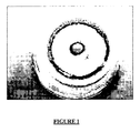
- the invention also comprises other arrangements which will emerge from the following description, which refers to examples of preparation of sputtering targets according to the invention and to a comparative example showing the resistance of two sputtering targets as prepared according to the method of the invention, and from the attached drawing in which figure 1 represents the photography of a solid sputtering target made from a sputtering composition containing a solid electrolyte, PHPS and glass fibers, after its use in a sputtering physical vapor deposition process;
- LiBO 2 lithium metaborate
- Li 2 SO 4 lithium sulphate
- Li 3 N lithium nitride
- a 13 gram batch composition has been chosen to prepare a sputtering target suitable for the comfortable fitness in the cathode.
- the LiBO 2 powder of 42 mol% equal to 4.372 gram, Li 2 SO 4 powder of 28 mol% equal to 6.442 gram and Li 3 N powder of 30 mol% equal to 2.187 gram are the weights taken for the starting materials.
- the lithium based powder mixture was then mixed and grinded well in a mortar until the obtaining of a uniform mixture.
- Glass fibers (sold under the reference “glass fiber tissue” by the firm SINTOFER) were cut into small pieces of 0.3 cm in length.
- the small pieces of 0.3 cm glass fibers of 0.7 in weight percent to the starting materials has been desired to use it in the sputtering target.
- These glass fibers were added in an amount of 0.7 in weight percent to the lithium powder mixture which corresponds to an amount of 0.091 g of glass fibers.
- the small pieces of glass fibers were then mixed with the lithium based powder mixture until obtaining an intimate mixture.
- PHPS represented 25 % in weight relative to the total weight of the starting material sputtering target composition.
- the mixture of starting material was then pressed using a stainless steel die.
- a sputtering target of 5 cm diameter suitable to fit in the cathode of thin film deposition chamber was prepared using this die. To do so, the mixture of starting materials was placed in the stainless steel die and the sputtering target was prepared by pressing 75 MPa. Applying more than 100 MPa would lead to spread the solvent out of the die and the powdered mixture.
- the resulting pressed mixture was then sintered at 180°C for 3 to 5 minutes which is the minimum duration required to evaporate the solvent.
- the sintered sputtering target had a thickness (t) of 0.51 cm, a diameter (d) of 5.0 cm and a weight (w) of 12.784 g.
- the actual density of that sputtering target was found to be 1.58 g/cm 3 .
- the apparent density of the sputtering target was calculated by the ratios of actual density of sputtering target to the theoretical density. The percentage of apparent density was found to be 74.0 %.
- the solid sputtering target prepared by this method was hard enough and suitable to be used in a sputtering physical vapor deposition process for the deposition of a thin solid electrolytes film onto the surface of a solid substrate.
- EXAMPLE 2 USE OF SOLID SPUTTERING TARGETS ACCORDING TO THE INVENTION FOR THE DEPOSITION OF A SOLID THIN ELECTROLYTE FILM ONTO A SUBSTRATE
- the sputtering target here-above prepared in example 1 was then used for the deposition of a solid thin electrolyte film onto the surface of a solid substrate.
- Sputtering parameters used for the deposition were the following:
- a thin tin disc was used in between the sputtering target and the cathode to have good thermal contact during thin film deposition.
- the target has sputtered up to 15 hours. Even after the 15 hours of sputtering the condition of the target was good, there was no crack on the sputtering target.
- the target was first sputtered under argon plasma and then under a nitrogen reactive plasma. The sputtered target at the end of the sputtering process is shown on annexed figure 1 .
- the sputtering target prepared in this process is durable for the deposition of thin film solid electrolytes by a sputtering deposition process.
- a alternative sputtering target also forming part of the present invention, made from the same starting material than the solid sputtering target as prepared in example 1 except glass fibers was also prepared according to the method described in example 1.
- This sputtering target was then used for the deposition of a solid thin electrolyte film onto the surface of a solid substrate.
- the deposition process was also carried out for 15 hours.
- This target resisted at least 11 hours to the conditions applied during the deposition process before breaking at the end of the process which is totally acceptable and very satisfying for a target which has been prepared according to a manufacturing method using only mild conditions.
Landscapes
- Chemical & Material Sciences (AREA)
- Engineering & Computer Science (AREA)
- Chemical Kinetics & Catalysis (AREA)
- Manufacturing & Machinery (AREA)
- Electrochemistry (AREA)
- General Chemical & Material Sciences (AREA)
- Materials Engineering (AREA)
- Mechanical Engineering (AREA)
- Metallurgy (AREA)
- Organic Chemistry (AREA)
- Secondary Cells (AREA)
- Physical Vapour Deposition (AREA)
- Primary Cells (AREA)
- Compositions Of Oxide Ceramics (AREA)
Abstract
The Invention relates to a cathodic sputtering target composition comprising at least a solid electrolyte and an inorganic carbon free polymer and to a method for the manufacturing of cathodic solid sputtering targets using such a composition. The invention also relates to solid sputtering targets obtained by such a method and to their use for the preparation of solid thin films by a sputtering physical vapour deposition process, in particular for the preparation of solid electrolyte thin films inside thin-film batteries.
Description
- The Invention relates to a cathodic sputtering target composition comprising at least a solid electrolyte and an inorganic carbon free polymer and to a method for the manufacturing of cathodic solid sputtering targets using such a composition. The invention also relates to solid sputtering targets obtained by such a method and to their use for the preparation of solid thin films by a sputtering physical vapour deposition process, in particular for the preparation of solid electrolyte thin films inside thin-film batteries.
- Solid-state thin film batteries are typically formed by stacking thin films on a substrate in such a way that the films cooperate to generate a voltage. The thin films typically include current collectors, a positive cathode, a negative anode, a solid electrolyte (film) and different protective layers.
- In a thin-film battery configuration, the cathode layer is separated from the anode layer by an electronically insulating layer of solid electrolyte material. This electrolyte layer provides two functions. The first function is to conduct the electrochemically active ions between the cathode and the anode. The second function is to prevent the direct exchange of electrons between the cathode and the anode so that the electronic current becomes available only in the external circuit of the battery.
- The solid electrolyte film and the electrode can be deposited onto the substrate by, for example, sputtering techniques such as radio frequency sputtering (RFS or RF sputtering) and RF magnetron sputtering (RFMS). These techniques are strictly physical vapor deposition (PVD) processes where charged ions of the plasma are bombarded on the surface of the target. Particles are ejected from the target and form a solid thin-film layer on the substrate.
- The present invention belongs to the field of solid electrolyte film deposition by PVD using cathodic sputtering targets.
- Common solid electrolytes that are contained in solid-state thin-film batteries must be free from any electronically conductive element, in particular they must be carbon-free, because they must prevent the direct exchange of electrons between the cathode and the anode to avoid any self discharge of the battery. They are often made from lithium in combination with one or several other elements such as phosphorus, silicium, sulphur, oxygen, boron, vanadium, etc.... As examples of lithium-based electrolytes used in the eighties, one can mention the following compositions: Li3.6Si0.6P0.4O4, 0.31 Li2SO4-0.31 Li2O-0.38 B2O3, 0.82 Li2O-0.08 V2O5-0.10 SiO2, 0.55 LiI-0.36 Li3PO4-0.99 P2S5. The electrolytes now generally used in microbatteries since the begining of the nineties are based on LiPON and are prepared by sputtering starting from a target of Li3PO4 in a nitrogen atmosphere. See, for instance,
U.S. Patents No. 5,569,520, April 30, 1996 and No.U.S. 5,597,660, January 28, 1997, issued to John B. Bates et al. The formula of LiPON is Li3.3PO3.9 N1.7 but can change slightly following the condition of its preparation with a slight change of its ionic conductivity. - Targets used during the sputtering processes used to make thin-film solid electrolytes can be manufactured by admixing and reacting together the different components of the target, before melting them to obtain a glass. This glass is however not resistant enough to be used as such in a sputtering deposition process (the glass breaks or crazes) and has to be further grinded, pressed in a mold (for example in the form of a disc) and finally sintered in air, in inert gas (nitrogen, argon,...) or under vacuum at temperatures that generally range from 400 to 600 °C but which can also reach 900°C or more before being usable in a sputtering process.
- This target manufacturing process is then long and difficult to put into practice at an industrial scale. In addition, the high temperatures needed by this process lead to the evaporation or to the sublimation of some of the most volatile compounds present in the mixtures that will change the final composition of the starting material and thus the final composition of the thin-film solid electrolyte that will be finally deposited onto the substrate.
- Another process sometimes usable to prepare sputtering targets consists in molding the mixtures of the different pulverulent components in a mold under pressure. However the targets thus obtained even dense are brittle and need to be further sintered to enhance their mechanical resistance. This sintering step has often to be repeated twice to obtain targets having satisfactory mechanical resistance properties.
- The use of processes involving such high temperatures is a limiting factor because it forbids the presence of volatile at low temperature compounds and/or of sensitive to high temperature compounds in the solid electrolyte starting composition.
- The Inventors have developed the subject of the invention in order to solve these problems. They have in particular set themselves the aim of providing a solid electrolyte composition the use of which is compatible with the presence of volatile at low temperature compounds and/or of sensitive to high temperature compounds in the final composition of the targets and with while leading to carbon-free cathodic sputtering targets (and more generally sputtering targets without any electronic conducting material) that have a satisfying resistance to the sputtering process and that can be manufactured more quickly and more easily by a process not necessitating too high temperatures.
- At this occasion, the Inventors have found that the use of a cathodic sputtering target starting composition comprising at least one solid electrolyte and at least one particular carbon-free inorganic polymer, during a sputtering target manufacturing process, resolves this technical problem and leads quickly and easily to sputtering targets in which the presence of volatile at low temperature compounds and/or sensitive to high temperature compounds is possible because the compulsory use of very high temperatures during the manufacturing process is thus avoided.
- A first subject of the present Invention is therefore a cathodic sputtering target starting composition comprising:
- at least one pulverulent ion-conductive solid electrolyte, said electrolyte being electronically insulating, and
- at least one carbon-free inorganic polymeric binder selected from the group consisting of perhydropolysilazanes, in an amount of at least 5% in weight relative to the total weight of said composition.
- Perhydropolysilazanes (PHPS) are known compounds sold under the tradename Polysilazane ® NN 120-20 by the firm Kyon which is a branch of Clariant Chemical Company. Usually this type of inorganic polymers is used as a coating for surfaces, especially for metal and polymer surfaces, as it is described for example in international application
WO 2005/085374 . Their use leads to thick protective coats which, for example, protect wheel rims against corrosion, scratching and eating-in of brake dust and also make easier to clean the rims. - However their use as component in solid electrolyte starting sputtering compositions for the preparation of sputtering targets useful for the sputtering deposition of solid thin-film electrolytes in batteries had never been envisaged.
- The Inventors have found that the use of PHPS, as a binder in solid electrolyte starting sputtering compositions, makes it possible to prepare dense targets and avoids the sintering of targets at high temperature. This helps to use temperature sensitive materials such as for example lithium nitride (Li3N), aluminum nitride (AlN) or silicium nitride (Si3N4) in the starting sputtering target composition. The materials contained in the target generally evaporate or are oxidized if the target is sintered at high temperature. Additionally, the Inventors have found that the use of PHPS is also of interest in the sense that it allows the incorporating, in the target, of a sufficient amount of nitrogen to prepare nitrogen rich thin film solid electrolytes. The incorporation of nitrogen into the film structure improves the ionic conductivity of thin film solid electrolytes which are the most promising materials for thin film micro battery devices.
- Therefore, by using a cathodic sputtering target starting composition comprising PHPS, it is now possible to prepare quickly and easily, at low temperatures, dense and solid sputtering targets having a very good ionic conductivity.
- According to a preferred embodiment of the invention, the PHPS are chosen among compounds of formula (I) below:

- The amount of PHPS is preferably ranging from 5 to about 30 % in weight, more preferably from about 15 to 25 % in weight, relative to the total weight of the sputtering composition. These percentages will of course depend on the material used for the electrolyte.
- In the sputtering target composition according to the invention, PHPS are preferably used in solution in a solvent. Solvents suitable for the PHPS are, in particular, organic solvents which contain no water and also no reactive groups (such as hydroxyl groups or amine groups) and that will totally evaporate during the sputtering process. These solvents are, for example, chosen among aliphatic or aromatic hydrocarbons, halogenated hydrocarbons, esters such as ethyl acetate or butyl acetate, ketones such as acetone or methyl ethyl ketone, ethers such as tetrahydrofuran or di-n-butylether, and also mono- and polyalkyle glycol dialkylethers (glymes), and mixtures thereof.
- Among these solvents, the use of ethers such as di-n-butylether is particularly preferred.
- When the PHPS is in solution in a solvent, the resulting PHPS solution preferably contains from 15-25 % in weight of PHPS for 75-85 % in weight of solvent.
- The pulverulent ion-conductive solid electrolytes are preferably chosen among lithium-, aluminum- and silicium-based electrolytes and mixtures thereof among which one can mention lithium borates (LiBO2, Li2B4O7, ...); lithium silicates (Li4SiO4, ...); lithium germanates (Li2GeO3, ...); lithium phosphates (Li3PO4); lithium salts such as lithium sulfates (Li2SO4, ...), lithium iodides, lithium chlorides and lithium fluorides; nitrides such as lithium nitride (Li3N), aluminum nitride (AlN), silicium nitride (Si3N4); and mixtures thereof.
- According to a preferred embodiment of the invention, the pulverulent ion-conductive solid electrolytes is a mixture comprising at least a lithium borate, a lithium sulfate, a lithium phosphate and lithium nitride.
- According to another preferred embodiment of the invention, the pulverulent ion-conductive solid electrolytes represent from 70 to 96 % in weight, more particularly from 77 to 90 % in weight, relative to the total weight of the sputtering composition.
- Deposition of solid electrolyte films having a thickness of about 1 µm generally involves a sputtering process lasting from about 2 to 10 hours or even more. Sputtering targets are sometimes not resistant enough to support high sputtering power and/or a long sputtering duration and may break or craze before the end of the sputtering process.
- Therefore, according to a preferred embodiment of the invention, the sputtering target composition further comprises at least one mechanical reinforcement, said reinforcement being free from any electronically conducting material.
- The presence of such a mechanical reinforcement in the sputtering target composition is not compulsory but enhances the resistance of the targets during the sputtering process thus authorizing a high sputtering power and/or a long sputtering duration.
- Preferably, the mechanical reinforcement represents from about 0.5 to about 0.8 % in weight relative to the total weight of the composition, (depending on the density of such a reinforcement).
- According to the invention the nature of the mechanical reinforcement is not critical as soon as it is free from any electronically conductive material, in particular free from carbon, to not increase the electronic conductivity of the resulting solid electrolyte films.
- The mechanical reinforcement can be chosen among fibers, particles, flakes, and/or fillers. As specific examples, on can mention fibers, particles, flakes, and/or fillers made of glass (E-glass, S-glass, D-glass), aluminum oxide, aluminum silica, asbestos, quartz (fused silica), or any other electronically insulating fillers and mixtures thereof.
- The mechanical reinforcement is preferably in the form of fibers.
- The length of the fibers has to be adjusted to the size of the target and may be easily determined by the man skilled in the art.
- For targets having a diameter ranging from 4 to 10 cm, the mechanical reinforcement is preferably chosen among fibers having a length of about 0.1 to 5 cm inclusive, more preferably of about 0.2 to 0.3 cm inclusive. In this case, the diameter of the fibers generally ranges from 0.1 to 0.5 µm and more preferably from 0.1 to 0.3 µm.
- The Inventors have found in this particular case that a higher length or a higher diameter of fibers causes the formation of a separate layer (cleavage) in the sputtering target after pressing the starting material. However, for larger targets having a size up to few meters, it is possible to use longer fibers, for examples fibers having a length of few meters. The length and the diameter of the fibers will be of course easily adapted to the final size of the target by the man skilled in the art.
- According to a particularly preferred embodiment of the present invention, and when the composition is designed for the preparation of a final target having a size ranging between 5 and 8 cm inclusive, the mechanical reinforcement consists of glass fibers of about 0.3 cm in length maximum and of an average diameter of about 0.1 µm.
- The cathodic sputtering target pulverulent composition that has been described above is generally in the form of a paste that can be prepared by the simple mixture of the different components contained therein according to classical methods well known by the one skilled in the art.
- Another object of the present invention is a process for the manufacturing of carbon-free solid cathodic sputtering targets comprising at least the following steps:
- a formatting step of a cathodic sputtering target composition as described above into a shape corresponding to the shape of the desired final target,
- a heating step of the resulting formatted composition at a temperature ranging from about 150°C to about 300 °C for about 3 to about 10 min.
- According to a first embodiment of that process, the formatting step is carried out by molding said cathodic sputtering target composition under a molding pressure ranging from 20 to 100 MPa, more preferably from 50 to 80 MPa, following the composition of the target. By this molding step, it is for example possible to obtain solid targets having the shape of a disc, or of any other form such as a square, a rectangle, a cylinder, etc.... For example, and for a lab scale target having the form of a disc, the diameter is typically 5 cm, and the thickness is around 3 to 5 mm. the thickness of the target may of course depend on the size of the target.
- According to a second embodiment of that process, the formatting step can also be carried out by applying a layer of said cathodic sputtering target composition on or around a solid support, for example around a cylindrical solid support.
- The heating step leads to the polymerization of the components contained in the cathodic sputtering target composition, the binder forming crosslinked chains with the solid electrolytes, firstly of the -Si-N-Si- type and secondly of the -Si-O-Si- type that confer to the resulting shaped solid resulting target a satisfying mechanical resistance.
- Preferably, the heating step is carried out at a temperature of between about 160 and 220°C inclusive, more preferably between about 180 and 200°C inclusive, for about 3 to 5 min. These particular conditions may of course vary slightly depending on the dimensions (for example diameter and thickness) and on the composition of the targets.
- The solid cathodic sputtering targets that are obtained according to that process constitute another subject matter of the present.
- Therefore, the invention also relates to cathodic sputtering solid target obtained according to the above-described process, wherein said targets are free from any electronically conductive material and comprise at least one solid material resulting from the polymerization, at a temperature ranging from about 150°C to about 300°C for about 3 to about 10 min, of a cathodic sputtering target starting composition as previously described, i.e. comprising:
- at least one pulverulent ion-conductive solid electrolyte, said electrolyte being electronically insulating, and
- at least one carbon-free inorganic polymeric binder selected from the group consisting of perhydropolysilazanes, in an amount of at least 5% in weight relative to the total weight of said composition.
- According to a preferred embodiment of the invention, these solid targets have the shape of a disc, a square, a rectangle, a cylinder or any shape with a thickness depending on the size of the target but in the range of a few mm to a few cm.
- These targets have generally a density ranging from about 1 g/cm3 to about 3 g/cm3.
- Finally, the invention also relates to the use of the above-mentioned cathodic sputtering solid targets for the sputtering physical vapor deposition of solid thin films onto the surface of a solid substrate, in particular for the deposition of solid thin electrolyte films inside thin-film batteries.
- These targets can also be used for any other solid thin film deposition needing targets with low melting point or low evaporation temperature compounds for example in electrochromic devices.
- As the polymerization occurs around 200°C, the invention allows the use, during the manufacturing of the target, of materials with low melting point or low evaporation temperature.
- Besides the arrangements above, the invention also comprises other arrangements which will emerge from the following description, which refers to examples of preparation of sputtering targets according to the invention and to a comparative example showing the resistance of two sputtering targets as prepared according to the method of the invention, and from the attached drawing in which
figure 1 represents the photography of a solid sputtering target made from a sputtering composition containing a solid electrolyte, PHPS and glass fibers, after its use in a sputtering physical vapor deposition process; - It should be clearly understood, however, that these examples are given only by way of illustration of the subject of the invention, of which they in no way constitute a limitation.
- A mixture of lithium metaborate (LiBO2) in 42 mol%, lithium sulphate (Li2SO4) in 28 mol% and lithium nitride (Li3N) in 30 mol% was the desired chemical composition to prepare the starting sputtering target composition.
- A 13 gram batch composition has been chosen to prepare a sputtering target suitable for the comfortable fitness in the cathode. The LiBO2 powder of 42 mol% equal to 4.372 gram, Li2SO4 powder of 28 mol% equal to 6.442 gram and Li3N powder of 30 mol% equal to 2.187 gram are the weights taken for the starting materials.
- Since lithium metaborate and lithium nitride are hygroscopic compounds which easily react with the moisture, all the powders were kept inside a glow box which was maintained at an inert dry argon gas atmosphere before their use. An X-ray analysis of the starting material was performed before starting the manufacturing of the target to check the formation of the phases present in the starting materials. The X-ray diffraction patterns of the starting materials were found conformed to the database.
- The lithium based powder mixture was then mixed and grinded well in a mortar until the obtaining of a uniform mixture.
- Glass fibers (sold under the reference "glass fiber tissue" by the firm SINTOFER) were cut into small pieces of 0.3 cm in length. The small pieces of 0.3 cm glass fibers of 0.7 in weight percent to the starting materials has been desired to use it in the sputtering target. These glass fibers were added in an amount of 0.7 in weight percent to the lithium powder mixture which corresponds to an amount of 0.091 g of glass fibers. The small pieces of glass fibers were then mixed with the lithium based powder mixture until obtaining an intimate mixture.
- 3.25 g of a 20 % (w/w) solution of PHPS in Di-n-butylether were then slowly added to the mixture of starting materials under mixing with a stainless steel spatula until obtaining a homogeneous mixture of starting materials.
- PHPS represented 25 % in weight relative to the total weight of the starting material sputtering target composition.
- The mixture of starting material was then pressed using a stainless steel die. A sputtering target of 5 cm diameter suitable to fit in the cathode of thin film deposition chamber was prepared using this die. To do so, the mixture of starting materials was placed in the stainless steel die and the sputtering target was prepared by pressing 75 MPa. Applying more than 100 MPa would lead to spread the solvent out of the die and the powdered mixture.
- The resulting pressed mixture was then sintered at 180°C for 3 to 5 minutes which is the minimum duration required to evaporate the solvent. The sintered sputtering target had a thickness (t) of 0.51 cm, a diameter (d) of 5.0 cm and a weight (w) of 12.784 g. The actual density of that sputtering target was found to be 1.58 g/cm3 .
- The theoretical density of the starting mixtures was calculated and it was found to be 2.14 g/cm3.
- The apparent density of the sputtering target was calculated by the ratios of actual density of sputtering target to the theoretical density. The percentage of apparent density was found to be 74.0 %.
- The solid sputtering target prepared by this method was hard enough and suitable to be used in a sputtering physical vapor deposition process for the deposition of a thin solid electrolytes film onto the surface of a solid substrate.
- The sputtering target here-above prepared in example 1 was then used for the deposition of a solid thin electrolyte film onto the surface of a solid substrate.
- Sputtering parameters used for the deposition were the following:
- Base pressure of sputtering chamber = 1x10⁻⁶ mbar
- Working pressure = 6x10⁻³ mbar
- Power applied to the sputtering target = 35 watts
- A thin tin disc was used in between the sputtering target and the cathode to have good thermal contact during thin film deposition. The target has sputtered up to 15 hours. Even after the 15 hours of sputtering the condition of the target was good, there was no crack on the sputtering target. The target was first sputtered under argon plasma and then under a nitrogen reactive plasma. The sputtered target at the end of the sputtering process is shown on annexed
figure 1 . - The sputtering target prepared in this process is durable for the deposition of thin film solid electrolytes by a sputtering deposition process.
- A alternative sputtering target also forming part of the present invention, made from the same starting material than the solid sputtering target as prepared in example 1 except glass fibers was also prepared according to the method described in example 1.
- This sputtering target was then used for the deposition of a solid thin electrolyte film onto the surface of a solid substrate.
- The same sputtering parameters and conditions than those used for the deposition of the film with the sputtering target as prepared according to example 1 were also used with this alternative sputtering target not containing any mechanical reinforcement.
- The deposition process was also carried out for 15 hours.
- This target resisted at least 11 hours to the conditions applied during the deposition process before breaking at the end of the process which is totally acceptable and very satisfying for a target which has been prepared according to a manufacturing method using only mild conditions.
Claims (28)
- A cathodic sputtering target starting composition comprising:- at least one pulverulent ion-conductive solid electrolyte, said electrolyte being electronically insulating and- at least one carbon-free inorganic polymeric binder selected from the group consisting of perhydropolysilazanes, in an amount of at least 5% in weight relative to the total weight of said composition.
- The composition of claim 1, wherein the perhydropolysilazanes are chosen among compounds of formula (I) below:

- The composition of claim 1 or 2, wherein the amount of perhydropolysilazane ranges from 5 to 30 % in weight relative to the total weight of said composition.
- The composition of claim 3, wherein the amount of perhydropolysilazane ranges from 15 to 25 % in weight relative to the total weight of said composition.
- The composition according to any one of the preceding claims, wherein perhydropolysilazanes are in solution in a solvent.
- The composition of claim 5, wherein said solvent is chosen among aliphatic or aromatic hydrocarbons, halogenated hydrocarbons, esters, ketones, ethers, mono- and polyalkyle glycol dialkylethers and mixtures thereof.
- The composition of claim 6, wherein said solvent is di-n-butylether.
- The composition according to any one of the preceding claims, wherein the pulverulent ion-conductive solid electrolytes are preferably chosen among lithium-, aluminum- and silicium-based electrolytes.
- The composition according to claim 8, wherein ion-conductive solid electrolytes are chosen among lithium borates; lithium silicates; lithium germanates; lithium phosphates; lithium salts; nitrides; and mixtures thereof.
- The composition according to claim 9 wherein the pulverulent ion conductive solid electrolytes is a mixture comprising at least a lithium borate, a lithium sulfate, a lithium phosphate and lithium nitride.
- The composition according to any one of the preceding claims, wherein, the pulverulent ion-conductive solid electrolytes represent from 70 to 96 % in weight, relative to the total weight of said composition.
- The composition according to claim 11, wherein the pulverulent ion-conductive solid electrolytes represent from 77 to 90 % in weight, relative to the total weight of said composition.
- The composition according to any one of the preceding claims, wherein said composition further comprises at least one mechanical reinforcement, said reinforcement being free from any electronically conducting material.
- The composition according to claim 13, wherein the mechanical reinforcement represents from 0.5 to 0.8 % in weight, relative to the total weight of said composition.
- The composition according to claim 13 or 14, wherein the mechanical reinforcement is chosen among fibers, particles, flakes, and/or fillers made of glass, aluminum oxide, aluminum silica, asbestos, quartz or any other electronically insulating fillers and mixtures thereof.
- The composition of claim 15, wherein the mechanical reinforcement is in the form of fibers.
- The composition of any one of claims 13 to 16, wherein said composition is designed for the preparation of a final target having a diameter ranging from 4 to 10 cm, and wherein the mechanical reinforcement is chosen among fibers having a length of about 0.1 to 5 cm inclusive.
- The composition of any one of claims 13 to 16, wherein said composition is designed for the preparation of a final target having a size ranging between 5 and 8 cm inclusive, and wherein the mechanical reinforcement consists of glass fibers of about 0.3 cm in length maximum and of an average diameter of about 0.1 µm.
- A process for the manufacturing of carbon-free solid cathodic sputtering targets, wherein said process comprises at least the following steps:- a formatting step of a cathodic sputtering target composition, said composition being as described in any one of claims 1 to 18, into a shape corresponding to the shape of the desired final target,- a heating step of the resulting formatted composition at a temperature ranging from 150°C to 300°C for 3 to 10 min.
- The process of claim 19, wherein the formatting step is carried out by molding said cathodic sputtering target composition under a molding pressure ranging from 20 to 100 MPa.
- The process of claim 20, wherein the molding pressure ranges from 50 to 80 MPa.
- The process of claim 19, wherein the formatting step is carried out by applying a layer of said cathodic sputtering target composition on or around a solid support.
- The process according to any one of claims 19 to 22, wherein the heating step is carried out at a temperature of between about 160 and 220°C inclusive for about 3 to 5 min.
- A solid cathodic sputtering target obtained according to the process as defined in any one of claims 19 to 23, wherein said targets are free from any electronically conductive material and comprise at least one solid material resulting from the polymerization, at a temperature ranging from 150°C to 300°C for 3 to 10 min, of a cathodic sputtering target starting composition as defined in any one of claims 1-18.
- The solid target of claim 24, wherein said target has a density ranging from 1 g/cm3 to 3 g/cm3.
- Use of a solid cathodic sputtering target as described in claim 24 or 25, for the sputtering physical vapor deposition of solid thin films onto the surface of a solid substrate.
- The use of claim 26, for the deposition of solid thin electrolyte films inside thin-film batteries.
- The use of claim 26, for the deposition of solid thin electrolyte films in electrochromic devices.
Priority Applications (5)
| Application Number | Priority Date | Filing Date | Title |
|---|---|---|---|
| EP08290576A EP2135973A1 (en) | 2008-06-18 | 2008-06-18 | Method for the manufacturing of sputtering targets using an inorganic polymer |
| PCT/IB2009/006324 WO2009153664A1 (en) | 2008-06-18 | 2009-06-17 | Method for the manufacturing of sputtering targets using an inorganic polymer |
| JP2011514145A JP5638519B2 (en) | 2008-06-18 | 2009-06-17 | Method for producing sputtering target using inorganic polymer |
| EP09766205.0A EP2297374B1 (en) | 2008-06-18 | 2009-06-17 | Method for the manufacturing of sputtering targets using an inorganic polymer |
| US12/997,998 US8652305B2 (en) | 2008-06-18 | 2009-06-17 | Method for manufacturing of sputtering targets using an inorganic polymer |
Applications Claiming Priority (1)
| Application Number | Priority Date | Filing Date | Title |
|---|---|---|---|
| EP08290576A EP2135973A1 (en) | 2008-06-18 | 2008-06-18 | Method for the manufacturing of sputtering targets using an inorganic polymer |
Publications (1)
| Publication Number | Publication Date |
|---|---|
| EP2135973A1 true EP2135973A1 (en) | 2009-12-23 |
Family
ID=39810147
Family Applications (2)
| Application Number | Title | Priority Date | Filing Date |
|---|---|---|---|
| EP08290576A Withdrawn EP2135973A1 (en) | 2008-06-18 | 2008-06-18 | Method for the manufacturing of sputtering targets using an inorganic polymer |
| EP09766205.0A Not-in-force EP2297374B1 (en) | 2008-06-18 | 2009-06-17 | Method for the manufacturing of sputtering targets using an inorganic polymer |
Family Applications After (1)
| Application Number | Title | Priority Date | Filing Date |
|---|---|---|---|
| EP09766205.0A Not-in-force EP2297374B1 (en) | 2008-06-18 | 2009-06-17 | Method for the manufacturing of sputtering targets using an inorganic polymer |
Country Status (4)
| Country | Link |
|---|---|
| US (1) | US8652305B2 (en) |
| EP (2) | EP2135973A1 (en) |
| JP (1) | JP5638519B2 (en) |
| WO (1) | WO2009153664A1 (en) |
Cited By (5)
| Publication number | Priority date | Publication date | Assignee | Title |
|---|---|---|---|---|
| US8470396B2 (en) | 2008-09-09 | 2013-06-25 | H.C. Starck Inc. | Dynamic dehydriding of refractory metal powders |
| US8703233B2 (en) | 2011-09-29 | 2014-04-22 | H.C. Starck Inc. | Methods of manufacturing large-area sputtering targets by cold spray |
| US8715386B2 (en) | 2006-10-03 | 2014-05-06 | H.C. Starck Inc. | Process for preparing metal powders having low oxygen content, powders so-produced and uses thereof |
| US9095932B2 (en) | 2006-12-13 | 2015-08-04 | H.C. Starck Inc. | Methods of joining metallic protective layers |
| US9783882B2 (en) | 2007-05-04 | 2017-10-10 | H.C. Starck Inc. | Fine grained, non banded, refractory metal sputtering targets with a uniformly random crystallographic orientation, method for making such film, and thin film based devices and products made therefrom |
Families Citing this family (4)
| Publication number | Priority date | Publication date | Assignee | Title |
|---|---|---|---|---|
| JP2011142034A (en) * | 2010-01-08 | 2011-07-21 | Sumitomo Electric Ind Ltd | Solid electrolyte membrane and method of manufacturing the same, and solid electrolyte battery |
| TWI611032B (en) | 2013-09-05 | 2018-01-11 | 攀時歐洲公司 | Conductive target material |
| JP7680441B2 (en) * | 2019-10-16 | 2025-05-20 | ビーエーエスエフ コーティングス ゲゼルシャフト ミット ベシュレンクテル ハフツング | Ultra-highly controlled radical polymerization |
| CN112687946B (en) * | 2020-12-23 | 2022-01-07 | 北京理工大学前沿技术研究院 | Method for preparing functional inorganic solid electrolyte powder by vacuum coating technology |
Citations (7)
| Publication number | Priority date | Publication date | Assignee | Title |
|---|---|---|---|---|
| JPH06204214A (en) * | 1992-12-28 | 1994-07-22 | Tonen Corp | Silicon nitride based target material for sputtering |
| US5569520A (en) | 1994-01-12 | 1996-10-29 | Martin Marietta Energy Systems, Inc. | Rechargeable lithium battery for use in applications requiring a low to high power output |
| US5597660A (en) | 1992-07-29 | 1997-01-28 | Martin Marietta Energy Systems, Inc. | Electrolyte for an electrochemical cell |
| US6407339B1 (en) * | 1998-09-04 | 2002-06-18 | Composite Technology Development, Inc. | Ceramic electrical insulation for electrical coils, transformers, and magnets |
| WO2005085374A1 (en) | 2004-03-04 | 2005-09-15 | Clariant International Ltd | Perhydropolysilazane- containing coatings for metal and polymer surfaces |
| US20060255716A1 (en) * | 2005-05-16 | 2006-11-16 | Koito Manufacturing Co., Ltd. | Light emitting apparatus and vehicle lamp |
| US20060292445A1 (en) * | 2005-06-24 | 2006-12-28 | Yasutaka Kogetsu | Negative electrode for lithium ion secondary battery and method for producing the negative electrode |
Family Cites Families (6)
| Publication number | Priority date | Publication date | Assignee | Title |
|---|---|---|---|---|
| US3850604A (en) * | 1972-12-11 | 1974-11-26 | Gte Laboratories Inc | Preparation of chalcogenide glass sputtering targets |
| US5208192A (en) * | 1990-01-12 | 1993-05-04 | Ethyl Corporation | Preceramic polysilazane compositions |
| US5628938A (en) * | 1994-11-18 | 1997-05-13 | General Electric Company | Method of making a ceramic composite by infiltration of a ceramic preform |
| JP3568499B2 (en) * | 2000-09-19 | 2004-09-22 | 日立マクセル株式会社 | Lithium-containing electrode material, method for producing the same, and electrochemical element using lithium-containing electrode material |
| US7488526B2 (en) * | 2005-11-22 | 2009-02-10 | Ricoh Company, Ltd. | Sputtering target and manufacturing method therefor, and optical recording medium and manufacturing method therefor |
| JP4641009B2 (en) * | 2006-07-07 | 2011-03-02 | 日本電信電話株式会社 | Method for forming LiNbO3 target and LiNbO3 thin film |
-
2008
- 2008-06-18 EP EP08290576A patent/EP2135973A1/en not_active Withdrawn
-
2009
- 2009-06-17 US US12/997,998 patent/US8652305B2/en not_active Expired - Fee Related
- 2009-06-17 JP JP2011514145A patent/JP5638519B2/en not_active Expired - Fee Related
- 2009-06-17 WO PCT/IB2009/006324 patent/WO2009153664A1/en not_active Ceased
- 2009-06-17 EP EP09766205.0A patent/EP2297374B1/en not_active Not-in-force
Patent Citations (7)
| Publication number | Priority date | Publication date | Assignee | Title |
|---|---|---|---|---|
| US5597660A (en) | 1992-07-29 | 1997-01-28 | Martin Marietta Energy Systems, Inc. | Electrolyte for an electrochemical cell |
| JPH06204214A (en) * | 1992-12-28 | 1994-07-22 | Tonen Corp | Silicon nitride based target material for sputtering |
| US5569520A (en) | 1994-01-12 | 1996-10-29 | Martin Marietta Energy Systems, Inc. | Rechargeable lithium battery for use in applications requiring a low to high power output |
| US6407339B1 (en) * | 1998-09-04 | 2002-06-18 | Composite Technology Development, Inc. | Ceramic electrical insulation for electrical coils, transformers, and magnets |
| WO2005085374A1 (en) | 2004-03-04 | 2005-09-15 | Clariant International Ltd | Perhydropolysilazane- containing coatings for metal and polymer surfaces |
| US20060255716A1 (en) * | 2005-05-16 | 2006-11-16 | Koito Manufacturing Co., Ltd. | Light emitting apparatus and vehicle lamp |
| US20060292445A1 (en) * | 2005-06-24 | 2006-12-28 | Yasutaka Kogetsu | Negative electrode for lithium ion secondary battery and method for producing the negative electrode |
Cited By (11)
| Publication number | Priority date | Publication date | Assignee | Title |
|---|---|---|---|---|
| US8715386B2 (en) | 2006-10-03 | 2014-05-06 | H.C. Starck Inc. | Process for preparing metal powders having low oxygen content, powders so-produced and uses thereof |
| US9095932B2 (en) | 2006-12-13 | 2015-08-04 | H.C. Starck Inc. | Methods of joining metallic protective layers |
| US9783882B2 (en) | 2007-05-04 | 2017-10-10 | H.C. Starck Inc. | Fine grained, non banded, refractory metal sputtering targets with a uniformly random crystallographic orientation, method for making such film, and thin film based devices and products made therefrom |
| US8470396B2 (en) | 2008-09-09 | 2013-06-25 | H.C. Starck Inc. | Dynamic dehydriding of refractory metal powders |
| US8961867B2 (en) | 2008-09-09 | 2015-02-24 | H.C. Starck Inc. | Dynamic dehydriding of refractory metal powders |
| US8703233B2 (en) | 2011-09-29 | 2014-04-22 | H.C. Starck Inc. | Methods of manufacturing large-area sputtering targets by cold spray |
| US8734896B2 (en) | 2011-09-29 | 2014-05-27 | H.C. Starck Inc. | Methods of manufacturing high-strength large-area sputtering targets |
| US9108273B2 (en) | 2011-09-29 | 2015-08-18 | H.C. Starck Inc. | Methods of manufacturing large-area sputtering targets using interlocking joints |
| US9120183B2 (en) | 2011-09-29 | 2015-09-01 | H.C. Starck Inc. | Methods of manufacturing large-area sputtering targets |
| US9293306B2 (en) | 2011-09-29 | 2016-03-22 | H.C. Starck, Inc. | Methods of manufacturing large-area sputtering targets using interlocking joints |
| US9412568B2 (en) | 2011-09-29 | 2016-08-09 | H.C. Starck, Inc. | Large-area sputtering targets |
Also Published As
| Publication number | Publication date |
|---|---|
| JP2011524947A (en) | 2011-09-08 |
| WO2009153664A1 (en) | 2009-12-23 |
| US8652305B2 (en) | 2014-02-18 |
| US20110147207A1 (en) | 2011-06-23 |
| EP2297374A1 (en) | 2011-03-23 |
| JP5638519B2 (en) | 2014-12-10 |
| EP2297374B1 (en) | 2018-10-10 |
Similar Documents
| Publication | Publication Date | Title |
|---|---|---|
| EP2297374B1 (en) | Method for the manufacturing of sputtering targets using an inorganic polymer | |
| US11239504B2 (en) | Protective layers for electrochemical cells | |
| US11984555B2 (en) | Sulfide-based solid electrolyte, method for producing the sulfide-based solid electrolyte, and method for producing all-solid-state battery | |
| JP2011524947A5 (en) | ||
| KR102493741B1 (en) | Ion-conductive composite for electrochemical cells | |
| US20230069989A1 (en) | Lithium metal electrodes | |
| Wu et al. | Robust and Fast‐Ion Conducting Interphase Empowering SiOx Anode Toward High Energy Lithium–Ion Batteries | |
| US11041248B2 (en) | Ceramic/polymer matrix for electrode protection in electrochemical cells, including rechargeable lithium batteries | |
| US20210135205A1 (en) | Protective layers for electrodes and electrochemical cells | |
| KR20180077287A (en) | Ionic conducting compounds and related uses | |
| Wu et al. | Effects of LAGP electrolyte on suppressing polysulfide shuttling in Li–S cells | |
| Yersak et al. | Hybrid Li‐S pouch cell with a reinforced sulfide glass solid‐state electrolyte film separator | |
| EP3012885B1 (en) | Ion-conductive composite for electrochemical cells | |
| EP3096376B1 (en) | Protective layers for electrodes | |
| KR100533934B1 (en) | Solid electrolyte for lithium secondary battery and a method for preparing the same | |
| US20250079461A1 (en) | Anode active material and its manufacturing method, lithium ion battery and all-solid-state lithium thin-film battery using the same | |
| FR3153821A1 (en) | POROUS SULFUR CERAMIC, ITS PREPARATION PROCESS AND ITS USES |
Legal Events
| Date | Code | Title | Description |
|---|---|---|---|
| PUAI | Public reference made under article 153(3) epc to a published international application that has entered the european phase |
Free format text: ORIGINAL CODE: 0009012 |
|
| AK | Designated contracting states |
Kind code of ref document: A1 Designated state(s): AT BE BG CH CY CZ DE DK EE ES FI FR GB GR HR HU IE IS IT LI LT LU LV MC MT NL NO PL PT RO SE SI SK TR |
|
| AX | Request for extension of the european patent |
Extension state: AL BA MK RS |
|
| STAA | Information on the status of an ep patent application or granted ep patent |
Free format text: STATUS: THE APPLICATION HAS BEEN WITHDRAWN |
|
| 17P | Request for examination filed |
Effective date: 20100618 |
|
| 18W | Application withdrawn |
Effective date: 20100624 |