EP2135473B1 - Information on reference signal structure for neighbouring cell measurements - Google Patents
Information on reference signal structure for neighbouring cell measurements Download PDFInfo
- Publication number
- EP2135473B1 EP2135473B1 EP08724334.1A EP08724334A EP2135473B1 EP 2135473 B1 EP2135473 B1 EP 2135473B1 EP 08724334 A EP08724334 A EP 08724334A EP 2135473 B1 EP2135473 B1 EP 2135473B1
- Authority
- EP
- European Patent Office
- Prior art keywords
- reference signal
- sub
- frames
- cell
- physical structure
- Prior art date
- Legal status (The legal status is an assumption and is not a legal conclusion. Google has not performed a legal analysis and makes no representation as to the accuracy of the status listed.)
- Active
Links
Images

Classifications
-
- H—ELECTRICITY
- H04—ELECTRIC COMMUNICATION TECHNIQUE
- H04L—TRANSMISSION OF DIGITAL INFORMATION, e.g. TELEGRAPHIC COMMUNICATION
- H04L5/00—Arrangements affording multiple use of the transmission path
- H04L5/003—Arrangements for allocating sub-channels of the transmission path
- H04L5/0048—Allocation of pilot signals, i.e. of signals known to the receiver
- H04L5/005—Allocation of pilot signals, i.e. of signals known to the receiver of common pilots, i.e. pilots destined for multiple users or terminals
-
- H—ELECTRICITY
- H04—ELECTRIC COMMUNICATION TECHNIQUE
- H04L—TRANSMISSION OF DIGITAL INFORMATION, e.g. TELEGRAPHIC COMMUNICATION
- H04L25/00—Baseband systems
- H04L25/02—Details ; arrangements for supplying electrical power along data transmission lines
- H04L25/0202—Channel estimation
- H04L25/0204—Channel estimation of multiple channels
-
- H—ELECTRICITY
- H04—ELECTRIC COMMUNICATION TECHNIQUE
- H04L—TRANSMISSION OF DIGITAL INFORMATION, e.g. TELEGRAPHIC COMMUNICATION
- H04L27/00—Modulated-carrier systems
- H04L27/26—Systems using multi-frequency codes
- H04L27/2601—Multicarrier modulation systems
- H04L27/2602—Signal structure
- H04L27/261—Details of reference signals
- H04L27/2613—Structure of the reference signals
-
- H—ELECTRICITY
- H04—ELECTRIC COMMUNICATION TECHNIQUE
- H04L—TRANSMISSION OF DIGITAL INFORMATION, e.g. TELEGRAPHIC COMMUNICATION
- H04L5/00—Arrangements affording multiple use of the transmission path
- H04L5/0001—Arrangements for dividing the transmission path
- H04L5/0014—Three-dimensional division
- H04L5/0023—Time-frequency-space
-
- H—ELECTRICITY
- H04—ELECTRIC COMMUNICATION TECHNIQUE
- H04L—TRANSMISSION OF DIGITAL INFORMATION, e.g. TELEGRAPHIC COMMUNICATION
- H04L5/00—Arrangements affording multiple use of the transmission path
- H04L5/0091—Signaling for the administration of the divided path
- H04L5/0094—Indication of how sub-channels of the path are allocated
-
- H—ELECTRICITY
- H04—ELECTRIC COMMUNICATION TECHNIQUE
- H04W—WIRELESS COMMUNICATION NETWORKS
- H04W24/00—Supervisory, monitoring or testing arrangements
- H04W24/02—Arrangements for optimising operational condition
-
- H—ELECTRICITY
- H04—ELECTRIC COMMUNICATION TECHNIQUE
- H04W—WIRELESS COMMUNICATION NETWORKS
- H04W48/00—Access restriction; Network selection; Access point selection
- H04W48/08—Access restriction or access information delivery, e.g. discovery data delivery
- H04W48/12—Access restriction or access information delivery, e.g. discovery data delivery using downlink control channel
-
- H—ELECTRICITY
- H04—ELECTRIC COMMUNICATION TECHNIQUE
- H04W—WIRELESS COMMUNICATION NETWORKS
- H04W72/00—Local resource management
- H04W72/20—Control channels or signalling for resource management
- H04W72/23—Control channels or signalling for resource management in the downlink direction of a wireless link, i.e. towards a terminal
-
- H—ELECTRICITY
- H04—ELECTRIC COMMUNICATION TECHNIQUE
- H04W—WIRELESS COMMUNICATION NETWORKS
- H04W72/00—Local resource management
- H04W72/30—Resource management for broadcast services
-
- H—ELECTRICITY
- H04—ELECTRIC COMMUNICATION TECHNIQUE
- H04W—WIRELESS COMMUNICATION NETWORKS
- H04W48/00—Access restriction; Network selection; Access point selection
- H04W48/20—Selecting an access point
-
- H—ELECTRICITY
- H04—ELECTRIC COMMUNICATION TECHNIQUE
- H04W—WIRELESS COMMUNICATION NETWORKS
- H04W88/00—Devices specially adapted for wireless communication networks, e.g. terminals, base stations or access point devices
- H04W88/08—Access point devices
Definitions
- the present invention relates to cellular radio communication and in particular to provide information to mobile terminals that enable the terminals to carry out measurements on cells neighbouring a cell the terminals camp in.
- the invention also relates to a radio base station adapted for providing the information, to a mobile terminal and a method for the mobile terminal.
- 3G LTE 3G Long Term Evolution
- This system will use OFDM as the downlink transmission scheme and will be able to operate on bandwidths ranging from 1.25 MHz to 20 MHz.
- data rates up to 100 Mb/s will be supported on the largest bandwidth.
- LTE will support both FDD and TDD as uplink/downlink duplexing schemes.
- LTE will also support multicast/broadcast services (MBSFN) on the same carrier as unicast data.
- MBSFN multicast/broadcast services
- An essential part in any cellular system is support of mobility, i.e., the possibility to move the connection between the terminal and the network from one cell to another cell.
- mobility i.e., the possibility to move the connection between the terminal and the network from one cell to another cell.
- neighboring cell measurements are used. While the connection is maintained in a serving cell, the terminal measures on some well defined signal in neighboring cells and reports the measurement result to the network. The network can then take a decision, for example based on a signal-to-noise ratio measurement made by the terminal, whether the connection should be moved from the serving cell to a new cell.
- the mobile terminal In order to carry out downlink coherent demodulation, the mobile terminal needs estimates of the downlink channel.
- a straightforward way to enable channel estimation in case of OFDM transmission is to insert known reference symbols into the OFDM time-frequency grid. In LTE, these reference symbols are jointly referred to as the LTE downlink reference signals.
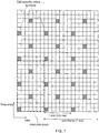
- Figure 1 is grid in the time frequency domain, with each square in the grid representing one subcarrier of one OFDM symbol. It serves to demonstrate the LTE downlink reference-signal structure assuming normal cyclic prefix, i.e. seven OFDM symbols per slot. As illustrated in figure 1 , downlink reference symbols are inserted within the first and the third last OFDM symbol of each slot and with a frequency-domain spacing of six subcarriers. Furthermore, there is a frequency-domain staggering of three subcarriers between the first and second reference symbols. Within each resource block, consisting of twelve subcarriers during one slot, there are thus four reference symbols. This is true for all sub-frames except sub-frames used for MBSFN-based broadcast/multicast, see further below.
- the structure in Figure 1 illustrates the reference-signal structure for the case of a single antenna.
- there is typically one reference signal transmitted for each antenna (the term 'antenna port' is used in the 3GPP specifications) and the location of the reference signals for the different antennas may be different.
- the reference signals can also be used for other purposes than coherent demodulation.
- One such example is neighboring cell measurements for mobility, where the terminal measures on the reference signal in neighboring cells to support mobility as described above.
- LTE should support both FDD- and TDD-based duplex arrangements.
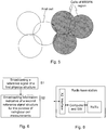
- Frequency Division Duplex as illustrated in the left part of figure 2 , implies that downlink and uplink transmission take place in different, sufficiently separated, frequency bands.
- Time Division Duplex as illustrated in the right part of figure 2 , implies that downlink and uplink transmission take place in different, non-overlapping time slots.
- TDD can operate in unpaired spectrum, whereas FDD requires paired spectrum.
- a guard time between downlink and uplink timeslots is needed. This can be created by omitting one or several OFDM symbols ("puncturing") in the last sub-frame before the downlink-to-uplink switch. In case a long guard time is needed, some of the reference symbols may need to be punctured in the last sub-frame prior to the switchpoint.
- the non-punctured part of a subframe used for downlink transmission is sometimes referred to as DwPTS.
- uplink and downlink transmission activity should be coordinated between neighboring cells. If this is not done, uplink transmission in one cell may interfere with downlink transmission in the neighboring cell (and vice versa) as illustrated in figure 3 .
- the terminal should only make neighbouring cell measurements during downlink transmission slots.
- Multi-cell broadcast implies transmission of the same information from multiple cells. By exploiting this at the terminal, effectively using signal power from multiple cell sites at the detection, a substantial improvement in coverage, or in higher broadcast data rates, can be achieved.
- this is implemented by transmitting not only identical signals from multiple cell sites, with identical coding and modulation, but also synchronize the transmission timing between the cells, the signal at the mobile terminal will appear exactly as a signal transmitted from a single cell site and subject to multi-path propagation. Due to the OFDM robustness to multi-path propagation, such multi-cell transmission, also referred to as Multicast-Broadcast Single Frequency Network (MBSFN) transmission, will then not only improve the received signal strength but also eliminate the inter-cell interference.
- MBSFN Multicast-Broadcast Single Frequency Network
- MBSFN transmission for multi-cell broadcast/multicast assumes the use of tight synchronization and time alignment of the signals transmitted from different cell sites.
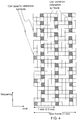
- a different reference signal structure is used as illustrated in figure 4 . This is needed as the effective channel seen by the terminal in case of MBSFN transmission appears as more frequency-selective than a single-cell unicast transmission.
- the reference signal structure will differ between slots in case of a mixed carrier transmitting both unicast and MBSFN services.
- MBSFN sub-frames only part of the cell-specific reference signal is present, it occurs in some the first OFDM symbols of the sub-frame as disclosed in figure 4 .
- the OFDM symbols carrying cell-specific reference symbol in the MBSFN sub-frame is a sub-set of the symbols used in a normal sub-frame for carrying cell-specific reference symbols, as can be concluded by comparing figure 1 and figure 4 .
- the terminal assumes the same configuration in the neighboring cell as the current cell.
- neighboring cells are configured differently, e.g., different guard times are used in neighboring cells or the MBSFN sub-frame are allocated differently in neighboring cells, the measurements made in the terminal would not correctly reflect the situation.
- NEC GROUP "Some issues related to MBSFN sub-frame structure"
- 3GPP DRAFT R1-071821 discusses two alternative physical formats of MBSFN sub-frames and that both may be used in different neighbouring cells in the same network.
- 3GPP DRAFT R1-070431 suggests for unicast common reference signal structure when unicast and SFN multicast transmissions present in a slot that the unicast reference signal occupies the same set of tones across all cells in the SFN area.
- the present invention solves the above problem by the subject-matter of the independent claims.
- TDD access mode is used, and not all neighbour cells have the same allocation of uplink and respectively downlink transmissions in various sub-frames.
- only sub-frames used for downlink transmissions by all cells neighbouring the first cell are informed of in broadcasting.
- the downlink sub-frames used by respective neighbour cell is indicated by the first cell.
- some sub-frame/s is/are used for multi-broadcast transmission in one or more of the neighbouring cells, whereas some other of the neighbour cells or the first cell transmit/s a normal sub-frame structure in the same time window.
- the multi-broadcast sub-frame has another more restricted allocation of symbols for the cell specific reference signal than for the normal sub-frame reference structure.
- An advantage of the invention is a terminal will make attempts to detect reference signals only in symbols that are carrying the reference signal. Thereby it is possible to have different regions of cells within which the same multicast information is broadcast, or within which the same allocation of sub-frames for respectively uplink and downlink transmissions is used.
- the present invention is particular needed in cells bordering the different regions of cells, to enable the terminals to accurately detect the reference signals of all the neighbour cells.
- the cell specific reference signal shall be used. Informing of the reference signal structure to be used for neighbouring cells measurement separately from the configuration in the serving cell provides several benefits.
- MBSFN transmissions in neighboring cells may use different sub-frames without affecting the possibility to perform accurate neighboring cell measurements.
- time aligned transmissions for MBSFN is useful in case the full benefits of MBSFN are to be exploited, at the border between different MBSFN regions this is not the case.
- the invention makes it possible to set up different regions of broadcasting the same MBSFN data. Within a region the same sub-frame allocation is used for broadcasting the MBSFN data. Thereby the broadcasting of information of interest only in a specific geographical area can be restricted to that area.
- Figure 5 illustrates a number of cells spread in the geography, some of them included in a MBSFN region.
- a first cell neighbouring the MBSFN region transmits normal sub-frames in the same time windows as is used in the MBSFN region for MBSFN sub-frames. Also other cells neighbouring the first cell transmit normal sub-frames in the same time window.
- the physical structure of the normal frame reference signals is disclosed in figure 1 .
- the reference signal structure of MBSFN sub-frames is disclosed in figure 4 .
- the symbols allocated to carry the reference signal in the MBSFN sub-frame overlap in their sequential position and on the frequency sub-carrier with symbols used for carrying reference signals in the normal sub-frames.
- the first cell broadcast information on the reference signal being carried by the symbols as in the structure of MBSFN broadcasting.
- Terminals camping in the first cell will then attempt to detect the cell specific reference signals according to the structure of the reference signal physical structure in the MBSFN sub-frame for all neighbouring cells albeit some of them transmit normal sub-frames.
- the symbols that carry cell specific reference signal in a MBSFN sub-frame are also used in a normal sub-frame for the same purpose.
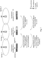
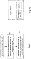
- FIG. 6 is a flowchart of the method of broadcasting in the first cell, according to the two steps:
- An alternative embodiment relates to a TDD access mode system when the first cell is located between two regions applying different allocations of sub-frames for respectively UL and DL transmission.
- a terminal can measure on a neighbour cell only when DL transmission direction is applied in the neighbour cell.
- TDD access mode When TDD access mode is applied, coordinating the UL and DL transmissions to the same sub-frames in all the cells of a region, and to synchronize the transmissions in the region is advantageous because interference between base stations and between terminals is mitigated.
- FIG. 7 This is illustrated in figure 7 , with a three cells, wherein cell No. 1 and cell No. 3 belongs to two different regions with cell no. 2 in between.
- the three cells have different allocations of sub-frames for respective UL and DL transmission directions.
- Cell No.1 to the left have 8 of its 10 sub-frames dedicated for the DL, and they are have the sequential numbers 0,1,2,3,5,6,7,8, leaving the remaining two sub-frames No. 4 and 9 for the UL direction.
- a cell No. 2 in the middle of figure 5 has 5 sub-frames allocated for the DL direction, i.e. sub-frames numbered 0,1,2,3,5.
- Two sub-frames are allocated for the UL direction, they are numbered 4 and 9.
- a cell No. 3, to the right in figure 5 has 5 sub-frames each to the UL and to the DL directions.
- the DL sub-frames are allocated to sub-frames numbers 0,1,2,3,5 and the remaining sub-frames are allocated to the UL direction.
- the information broadcast by is not only sub-frame specific but also neighbour cell specific.
- cell No. 2 broadcast that sub-frames No. 0,1,2,3,5,6,7,8 are available for measurements on cell No. 1, whereas for measurements on cell No. 3 only sub-frames 0,1,2,3,5 may be used.
- This alternative embodiment is also disclosed in the text of figure 7 .
- the sub-frame structure is neighbour cell specific.
- the information on the reference signal structure is alternatively cell specific for the various neighbour cells.
- some of the symbols normally used for carrying the reference signals may be punctured for increasing the Guard period between sub-frames for DL to UL transmission.
- the last reference symbols in the last DL sub-frame may then be lost.
- the first cell shall then broadcast information of the reference signal physical structure in the same way as is described for the MBSFN embodiment.
- MBSFN transmission may occur both in FDD mode and in TDD mode.
- TDD mode information on what sub-frames to use as well as physical reference signal structure within each used sub-frame need be broadcast.
- the information indicative of the reference signal structure need not relate to the all the symbols carrying the reference signals or to all sub-frames used in DL, it may be restricted to sub- frames or to symbols that shall be used by the mobile terminal for making neighbour cell measurements. This is in particular relevant to the embodiments when the information is indicative of the smallest subset of sub-frames or of symbols that are used by all neighbour cells.
- the broadcast information only need be indicative of a physical structure.
- different classes of physical structures may have been predefined, and the first cell just broadcast the classification of the different sub-frames.
- FIG 8 is a block diagram of a radio base station adapted for performing the invention.
- the radio base station comprises a radio transceiver including an antenna system, and a data processor controlling the operation of the radio base station according to software.
- the software is updated to control the broadcasting including an indication of the second reference signal according to the method.
- the radio base station also comprises an X2 interface for connection to neighbouring radio base station.
- the signalling information received via the X2 interface is detected by the data processor and the indication of the second reference signal structure as broadcast can be updated autonomously by the radio base station in accordance with information received via the X2 interface.
- Figure 9 is a flowchart of the steps performed by a mobile terminal, or UE (User Equipment) as is the name of the LTE mobile terminal.
- UE User Equipment
- the mobile is camping in a first cell, either in connected mode with the first cell acting serving cell or in idle mode.
- the first cell transmits a cell specific reference signal according to a first physical structure.
- the mobile terminal reads indication on a second physical structure for a reference signal.
- the indication is broadcast in the first cell.
- the terminal measures a reference signal in one or more neighbouring cells, assuming the reference signal is carried by symbols according to the indicated second physical structure.
- the indication of second physical structure typically indicates one in a predefined a set of physical structures.
- the mobile terminal as manufactured or as including a SIM-card (Subscription Identity Module), possesses information on the set of possible physical structures for the reference signal.
- SIM-card Subscribescription Identity Module
- Figure 10 is a block diagram of the mobile terminal.
- a transceiver including an antenna, and computer including software.
- the computer and software may be distributed and part of it residing in the SIM-card.
- the software is adapted for detecting the broadcast indication of a the second physical structure of the reference signal, and to control the measuring of reference signal in neighbouring cells to be made on the symbols that is indicated to carry the reference signal.
- the LTE is also standardised for alternative multi-antenna transmission techniques and then typically one reference signal is transmitted for each antenna and the physical structure of symbols assigned for carrying the respective reference signal within the sub-frames, is almost the same.
- the reference signal structure of antenna 1 is the same as the reference signal for antenna 0 with, the exception of the OFDM symbol is shifted 3 sub-carriers in the frequency domain relative to the symbols on carrier 0.
- the frame timing on the two antennas is synchronized.
- the physical structure of the plural reference signals allocated to multi-antenna cells is one of the predefined sets of physical structure the mobile terminal possesses information on. Accordingly the multi-antenna system physical structure may be broadcast in a cell, and the mobile terminals assume this physical structure when making neighbour cell measurements.
Description
- The present invention relates to cellular radio communication and in particular to provide information to mobile terminals that enable the terminals to carry out measurements on cells neighbouring a cell the terminals camp in. The invention also relates to a radio base station adapted for providing the information, to a mobile terminal and a method for the mobile terminal.
- In the forthcoming evolution of the mobile cellular standards like GSM and WCDMA, new transmission techniques like OFDM are likely to occur. Furthermore, in order to have a smooth migration from the existing cellular systems to the new high capacity high data rate system in existing radio spectrum, the new system has to be able to operate in a flexible bandwidth. An example of such a new flexible cellular system is 3G Long Term Evolution (3G LTE) that can be seen as an evolution of the 3G WCDMA standard. This system will use OFDM as the downlink transmission scheme and will be able to operate on bandwidths ranging from 1.25 MHz to 20 MHz. Furthermore, data rates up to 100 Mb/s will be supported on the largest bandwidth. LTE will support both FDD and TDD as uplink/downlink duplexing schemes. Furthermore, LTE will also support multicast/broadcast services (MBSFN) on the same carrier as unicast data.
- An essential part in any cellular system is support of mobility, i.e., the possibility to move the connection between the terminal and the network from one cell to another cell. To support this, neighboring cell measurements are used. While the connection is maintained in a serving cell, the terminal measures on some well defined signal in neighboring cells and reports the measurement result to the network. The network can then take a decision, for example based on a signal-to-noise ratio measurement made by the terminal, whether the connection should be moved from the serving cell to a new cell.
- In order to carry out downlink coherent demodulation, the mobile terminal needs estimates of the downlink channel. A straightforward way to enable channel estimation in case of OFDM transmission is to insert known reference symbols into the OFDM time-frequency grid. In LTE, these reference symbols are jointly referred to as the LTE downlink reference signals.
-
Figure 1 is grid in the time frequency domain, with each square in the grid representing one subcarrier of one OFDM symbol. It serves to demonstrate the LTE downlink reference-signal structure assuming normal cyclic prefix, i.e. seven OFDM symbols per slot. As illustrated infigure 1 , downlink reference symbols are inserted within the first and the third last OFDM symbol of each slot and with a frequency-domain spacing of six subcarriers. Furthermore, there is a frequency-domain staggering of three subcarriers between the first and second reference symbols. Within each resource block, consisting of twelve subcarriers during one slot, there are thus four reference symbols. This is true for all sub-frames except sub-frames used for MBSFN-based broadcast/multicast, see further below. - The structure in
Figure 1 illustrates the reference-signal structure for the case of a single antenna. For various multi-antenna transmission techniques, there is typically one reference signal transmitted for each antenna (the term 'antenna port' is used in the 3GPP specifications) and the location of the reference signals for the different antennas may be different. - The reference signals can also be used for other purposes than coherent demodulation. One such example is neighboring cell measurements for mobility, where the terminal measures on the reference signal in neighboring cells to support mobility as described above.
- One important part of the LTE requirements in terms of spectrum flexibility is the possibility to deploy LTE-based radio-access in both paired and unpaired spectrum, i.e., LTE should support both FDD- and TDD-based duplex arrangements. Frequency Division Duplex (FDD) as illustrated in the left part of
figure 2 , implies that downlink and uplink transmission take place in different, sufficiently separated, frequency bands. Time Division Duplex (TDD), as illustrated in the right part offigure 2 , implies that downlink and uplink transmission take place in different, non-overlapping time slots. Thus, TDD can operate in unpaired spectrum, whereas FDD requires paired spectrum. - To support TDD operation, a guard time between downlink and uplink timeslots is needed. This can be created by omitting one or several OFDM symbols ("puncturing") in the last sub-frame before the downlink-to-uplink switch. In case a long guard time is needed, some of the reference symbols may need to be punctured in the last sub-frame prior to the switchpoint. The non-punctured part of a subframe used for downlink transmission is sometimes referred to as DwPTS.
- In case of TDD operation, uplink and downlink transmission activity should be coordinated between neighboring cells. If this is not done, uplink transmission in one cell may interfere with downlink transmission in the neighboring cell (and vice versa) as illustrated in
figure 3 . Related to measurements, the terminal should only make neighbouring cell measurements during downlink transmission slots. - Multi-cell broadcast implies transmission of the same information from multiple cells. By exploiting this at the terminal, effectively using signal power from multiple cell sites at the detection, a substantial improvement in coverage, or in higher broadcast data rates, can be achieved. In LTE, this is implemented by transmitting not only identical signals from multiple cell sites, with identical coding and modulation, but also synchronize the transmission timing between the cells, the signal at the mobile terminal will appear exactly as a signal transmitted from a single cell site and subject to multi-path propagation. Due to the OFDM robustness to multi-path propagation, such multi-cell transmission, also referred to as Multicast-Broadcast Single Frequency Network (MBSFN) transmission, will then not only improve the received signal strength but also eliminate the inter-cell interference. Thus, with OFDM, multi-cell broadcast/multicast capacity may eventually only be limited by noise and can then, in case of small cells, reach extremely high values.
- It should also be noted that the use of MBSFN transmission for multi-cell broadcast/multicast assumes the use of tight synchronization and time alignment of the signals transmitted from different cell sites.
- For MBSFN, a different reference signal structure is used as illustrated in
figure 4 . This is needed as the effective channel seen by the terminal in case of MBSFN transmission appears as more frequency-selective than a single-cell unicast transmission. Thus, as unicast data and MBSFN transmissions are time multiplexed in different time slots, the reference signal structure will differ between slots in case of a mixed carrier transmitting both unicast and MBSFN services. In MBSFN sub-frames, only part of the cell-specific reference signal is present, it occurs in some the first OFDM symbols of the sub-frame as disclosed infigure 4 . The OFDM symbols carrying cell-specific reference symbol in the MBSFN sub-frame is a sub-set of the symbols used in a normal sub-frame for carrying cell-specific reference symbols, as can be concluded by comparingfigure 1 andfigure 4 . - Typically, the terminal assumes the same configuration in the neighboring cell as the current cell. In case neighboring cells are configured differently, e.g., different guard times are used in neighboring cells or the MBSFN sub-frame are allocated differently in neighboring cells, the measurements made in the terminal would not correctly reflect the situation.
- NEC GROUP: "Some issues related to MBSFN sub-frame structure", 3GPP DRAFT R1-071821 discusses two alternative physical formats of MBSFN sub-frames and that both may be used in different neighbouring cells in the same network.
- QUALCOMM EUROPE: "DL RS for Multiplexed Unicast and MBMS Configurations", 3GPP DRAFT R1-070431 suggests for unicast common reference signal structure when unicast and SFN multicast transmissions present in a slot that the unicast reference signal occupies the same set of tones across all cells in the SFN area.
- ALCATEL-LUCENT: "Reference Signal Structure for Multi-antenna EBMMS Transmission", 3GPP DRAFT R1-070523, presents two candidate signals for multi-antenna E-MBMS transmission based on the cell-common scrambled pilot structure considering time-division multiplex with unicast services.
- The present invention solves the above problem by the subject-matter of the independent claims.
- Advantageous embodiments of the invention are subject matters of the dependent claims. Further aspects of the invention not covered by the claims are to be understood as examples useful for better understanding of the invention.
- In one embodiment, TDD access mode is used, and not all neighbour cells have the same allocation of uplink and respectively downlink transmissions in various sub-frames. According to the first embodiment of the invention, only sub-frames used for downlink transmissions by all cells neighbouring the first cell are informed of in broadcasting. Alternatively the downlink sub-frames used by respective neighbour cell is indicated by the first cell.
- In a second alternative embodiment, some sub-frame/s is/are used for multi-broadcast transmission in one or more of the neighbouring cells, whereas some other of the neighbour cells or the first cell transmit/s a normal sub-frame structure in the same time window. The multi-broadcast sub-frame has another more restricted allocation of symbols for the cell specific reference signal than for the normal sub-frame reference structure. In the second embodiment, is broadcast a structure of a sub-set of symbols allocated to symbols in common for both the multi-broadcast sub-frame and for the normal sub-frame. Thereby the terminal will use only the subset of symbols for measures on the reference signal in the neighbour cells.
- An advantage of the invention is a terminal will make attempts to detect reference signals only in symbols that are carrying the reference signal. Thereby it is possible to have different regions of cells within which the same multicast information is broadcast, or within which the same allocation of sub-frames for respectively uplink and downlink transmissions is used. The present invention is particular needed in cells bordering the different regions of cells, to enable the terminals to accurately detect the reference signals of all the neighbour cells.
-
-
Figure 1 is grid in the time frequency domain, with each square in the gri .d representing an OFDM symbol. -
Figure 2 is an illustration of FDD mode versus TDD mode, with the respective allocation of time and frequency to the uplink and downlink transmissions -
Figure 3 is a view of two cells and a terminal in each cell illustrating a TDD mode interference situation. -
Figure 4 is the same type of figure asfigure 1 , illustrating a different allocation of symbols for carrying the reference signal. -
Figure 5 is a view of cells. -
Figure 6 is a flowchart of method. -
Figure 7 is an illustration of different allocation of sub-frames for respective uplink and downlink transmissions in three cells. -
Figure 8 is a block diagram of a radio base station. -
Figure 9 is a flowchart of a method for a mobile station. -
Figure 10 is a block diagram of a mobile terminal. - For neighbour cell measurements the cell specific reference signal shall be used. Informing of the reference signal structure to be used for neighbouring cells measurement separately from the configuration in the serving cell provides several benefits.
- MBSFN transmissions in neighboring cells may use different sub-frames without affecting the possibility to perform accurate neighboring cell measurements. Although using time aligned transmissions for MBSFN is useful in case the full benefits of MBSFN are to be exploited, at the border between different MBSFN regions this is not the case. The invention makes it possible to set up different regions of broadcasting the same MBSFN data. Within a region the same sub-frame allocation is used for broadcasting the MBSFN data. Thereby the broadcasting of information of interest only in a specific geographical area can be restricted to that area.
Figure 5 illustrates a number of cells spread in the geography, some of them included in a MBSFN region. A first cell neighbouring the MBSFN region, transmits normal sub-frames in the same time windows as is used in the MBSFN region for MBSFN sub-frames. Also other cells neighbouring the first cell transmit normal sub-frames in the same time window. The physical structure of the normal frame reference signals is disclosed infigure 1 . The reference signal structure of MBSFN sub-frames is disclosed infigure 4 . The symbols allocated to carry the reference signal in the MBSFN sub-frame overlap in their sequential position and on the frequency sub-carrier with symbols used for carrying reference signals in the normal sub-frames. The first cell broadcast information on the reference signal being carried by the symbols as in the structure of MBSFN broadcasting. Terminals camping in the first cell will then attempt to detect the cell specific reference signals according to the structure of the reference signal physical structure in the MBSFN sub-frame for all neighbouring cells albeit some of them transmit normal sub-frames. The symbols that carry cell specific reference signal in a MBSFN sub-frame are also used in a normal sub-frame for the same purpose. -
Figure 6 is a flowchart of the method of broadcasting in the first cell, according to the two steps: - Broadcasting a first reference signal, and that has a first physical structure (S1). In the situation described as an example the first cell is not included in the MBSFN region and the first reference signal structure is the structure of the normal sub-frame.
- Broadcasting information indicative of a second reference signal structure and that is to be used by terminals for performing neighbour cell measurements.
- An alternative embodiment relates to a TDD access mode system when the first cell is located between two regions applying different allocations of sub-frames for respectively UL and DL transmission. A terminal can measure on a neighbour cell only when DL transmission direction is applied in the neighbour cell. When TDD access mode is applied, coordinating the UL and DL transmissions to the same sub-frames in all the cells of a region, and to synchronize the transmissions in the region is advantageous because interference between base stations and between terminals is mitigated. However, there might be a need to differ the balance of allocation of UL resources versus DL resources in response to different demand in different regions. Different uplink-downlink allocations can be used in different cells, assuming proper planning. This is illustrated in
figure 7 , with a three cells, wherein cell No. 1 and cell No. 3 belongs to two different regions with cell no. 2 in between. The three cells have different allocations of sub-frames for respective UL and DL transmission directions. Cell No.1 to the left have 8 of its 10 sub-frames dedicated for the DL, and they are have thesequential numbers figure 5 , has 5 sub-frames allocated for the DL direction, i.e. sub-frames numbered 0,1,2,3,5. Two sub-frames are allocated for the UL direction, they are numbered 4 and 9. Three sub-frames, No. 6-8 are left unused. A cell No. 3, to the right infigure 5 , has 5 sub-frames each to the UL and to the DL directions. The DL sub-frames are allocated tosub-frames numbers - In cell No. 2, the broadcast information on which sub-frames to use for performing neighbour cell measurements, would, in a first alternative be restricted to sub-frames no. 0,1,2,3,5 because this group is common for both neighbour cell No.1 and neighbour cell No. 3. Also broadcast information in cell No. 1, and cell No. 3 for measurements on respective neighbours should be restricted to the use of sub-frames No. 0,1,2,3,5.
- In an alternative embodiment the information broadcast by is not only sub-frame specific but also neighbour cell specific. Thus, cell No. 2 broadcast that sub-frames No. 0,1,2,3,5,6,7,8 are available for measurements on cell No. 1, whereas for measurements on cell No. 3
only sub-frames figure 7 . - Also in the case of MBSFN transmission, the sub-frame structure is neighbour cell specific. The information on the reference signal structure is alternatively cell specific for the various neighbour cells.
- In the TDD mode, some of the symbols normally used for carrying the reference signals may be punctured for increasing the Guard period between sub-frames for DL to UL transmission. The last reference symbols in the last DL sub-frame may then be lost. The first cell shall then broadcast information of the reference signal physical structure in the same way as is described for the MBSFN embodiment.
- It should further be noted that MBSFN transmission may occur both in FDD mode and in TDD mode. In the case of TDD mode information on what sub-frames to use as well as physical reference signal structure within each used sub-frame need be broadcast.
- The information indicative of the reference signal structure, need not relate to the all the symbols carrying the reference signals or to all sub-frames used in DL, it may be restricted to sub- frames or to symbols that shall be used by the mobile terminal for making neighbour cell measurements. This is in particular relevant to the embodiments when the information is indicative of the smallest subset of sub-frames or of symbols that are used by all neighbour cells.
- Moreover, the broadcast information only need be indicative of a physical structure. For example different classes of physical structures may have been predefined, and the first cell just broadcast the classification of the different sub-frames.
-
Figure 8 is a block diagram of a radio base station adapted for performing the invention. The radio base station comprises a radio transceiver including an antenna system, and a data processor controlling the operation of the radio base station according to software. The software is updated to control the broadcasting including an indication of the second reference signal according to the method. The radio base station also comprises an X2 interface for connection to neighbouring radio base station. The signalling information received via the X2 interface is detected by the data processor and the indication of the second reference signal structure as broadcast can be updated autonomously by the radio base station in accordance with information received via the X2 interface. -
Figure 9 is a flowchart of the steps performed by a mobile terminal, or UE (User Equipment) as is the name of the LTE mobile terminal. Initially the mobile is camping in a first cell, either in connected mode with the first cell acting serving cell or in idle mode. The first cell transmits a cell specific reference signal according to a first physical structure. In the first step, 91, the mobile terminal reads indication on a second physical structure for a reference signal. The indication is broadcast in the first cell. In a next step, 92, the terminal measures a reference signal in one or more neighbouring cells, assuming the reference signal is carried by symbols according to the indicated second physical structure. - The indication of second physical structure typically indicates one in a predefined a set of physical structures. The mobile terminal as manufactured or as including a SIM-card (Subscription Identity Module), possesses information on the set of possible physical structures for the reference signal.
-
Figure 10 is a block diagram of the mobile terminal. In comprises a transceiver, including an antenna, and computer including software. The computer and software may be distributed and part of it residing in the SIM-card. The software is adapted for detecting the broadcast indication of a the second physical structure of the reference signal, and to control the measuring of reference signal in neighbouring cells to be made on the symbols that is indicated to carry the reference signal. - So far the invention has been described in a LTE system applying a single antenna. The LTE is also standardised for alternative multi-antenna transmission techniques and then typically one reference signal is transmitted for each antenna and the physical structure of symbols assigned for carrying the respective reference signal within the sub-frames, is almost the same. The reference signal structure of
antenna 1 is the same as the reference signal forantenna 0 with, the exception of the OFDM symbol is shifted 3 sub-carriers in the frequency domain relative to the symbols oncarrier 0. The frame timing on the two antennas is synchronized. - The physical structure of the plural reference signals allocated to multi-antenna cells, is one of the predefined sets of physical structure the mobile terminal possesses information on. Accordingly the multi-antenna system physical structure may be broadcast in a cell, and the mobile terminals assume this physical structure when making neighbour cell measurements.
-
- DL downlink
- UL uplink
- UE User Equipment, i.e. the name of the mobile terminal in the LTE system
- MBSFN - a 3GPP specific term used for multibroadcast, i.e. synchronized broadcasting of the same information in a plurality of cells. In some literature this is also referred to as Single-Frequency Network (SFN).
Claims (17)
- A method of broadcasting downlink in a first cell in a network comprising a plurality of cells organized into two or more Multicast-Broadcast Single Frequency Network, MBSFN, regions with respect to allocation of normal sub-frames and of MBSFN sub-frames, the method comprising the steps of:broadcasting (S1) a first reference signal, according to a first reference signal physical structure for the normal sub-frames, wherein the first reference signal is carried by predefined OFDM symbols and by predefined sub-carriers within the normal sub-frames according to the first reference signal physical structure, wherein predefined OFDM symbols that carry reference signals differ between the normal sub-frame and the MBSFN sub-frame,characterised by further broadcasting (S2) information indicative of a second reference signal physical structure for carrying a second reference signal in a neighbouring cell.
- The method according to claim 1, wherein the information indicative of the second reference signal physical structure relates to the allocation of MBSFN sub-frames.
- The method according to claim 1, wherein said information indicative of the second reference signal physical structure is for use by mobile terminals to perform neighbour cell measurements.
- The method according to claim 1, wherein the information on the second reference signal physical structure includes information on which of the sub-frames to use for neighbour cell measurements.
- The method according to claim 1 or 4, wherein the information on the second reference signal physical structure is indicative of which OFDM symbols in each sub-frame to use for neighbour cell measurements.
- The method according to claim 5 wherein the OFDM symbols carrying the second reference signal are allocated to one or more of a set of sub-carriers and to one or more predefined positions in a sequence of OFDM symbols within each sub-frame.
- The method according to claim 5, wherein only OFDM symbols used by all the neighbour cells for carrying reference signals in each sub-frame are informed of for the purpose of reference signal measurements.
- The method according to claim 1, wherein the second reference signal physical structure is indicated by a sub-frame classification.
- The method according to claim 1, wherein the first and the second reference signals are specific for the cell they are broadcasted in.
- A radio base station for a network comprising a plurality of cells organized into two or more Multicast-Broadcast Single Frequency Network, MBSFN, regions with respect to allocation of normal sub-frames and of MBSFN sub-frames, the radio base station comprising:a transceiver that is arranged for broadcasting (S1) a first reference signal according to a first reference signal physical structure for the normal sub-frames, and wherein the first reference signal is carried by predefined OFDM symbols and by predefined sub-carriers within the normal sub-frames, according to the first reference signal physical structure, wherein predefined OFDM symbols that carry reference signals differ between the normal sub-frame and the MBSFN sub-frame,characterised in thatthe transceiver is further arranged to broadcast (S2) information indicative of a second reference signal physical structure for carrying a second reference signal in a neighbouring cell.
- The radio base station of claim 10, wherein the information indicative of the second reference signal physical structure relates to the allocation of MBSFN sub-frames.
- A method performed by a mobile terminal that is camping in a first cell of a network comprising a plurality of cells organized into two or more Multicast-Broadcast Single Frequency Network, MBSFN, regions with respect to allocation of normal sub-frames and of MBSFN sub-frames, and the first cell is broadcasting a first reference signal according to a first reference signal physical structure for the normal sub-frames, wherein the first reference signal is carried by predefined OFDM symbols and by predefined sub-carriers within the normal sub-frames according to the first reference signal physical structure, wherein predefined OFDM symbols that carry reference signals differ between the normal sub-frame and the MBSFN sub-frame, the method characterised by the steps of:- detecting (91) as broadcast in the first cell an indication of a second reference signal physical structure that carries a second reference signal in a cell neighbouring the first cell, and,- measuring (92) the second reference signal in downlink sub-frames according to the detected indication.
- The method of claim 12, wherein the detected indication further relates to OFDM symbols carrying the second reference signal, and wherein the measuring on the second reference signal is made on the OFDM symbols as indicated.
- The method according to claim 12, wherein the detected indication of the second reference signal physical structure relates to the allocation of MBSFN sub-frames
- A mobile terminal, for connecting to a first cell in a network comprising a plurality of cells organized into two or more Multicast-Broadcast Single Frequency Network, MBSFN, regions with respect to allocation of normal sub-frames and of MBSFN sub-frames, wherein the first cell is broadcasting a first reference signal according to a first reference signal physical structure for normal sub-frames, wherein the first reference signal is carried by predefined OFDM symbols and by predefined sub-carriers within the normal sub-frames according to the first reference signal physical structure, wherein predefined OFDM symbols that carry reference signals differ between the normal sub-frame and the MBSFN sub-frame, the mobile terminal comprising:a transceiver;and a computer;characterized by the computer with software and via the transceiver being operable to,detect (91) an indication that is broadcast in the first cell and that relates to a second reference signal physical structure that carries a second reference signal in a cell neighbouring the first cell,measure (92) the second reference signal in downlink sub-frames according to the detected indication.
- The mobile terminal of claim 15, wherein the detected indication further relates to OFDM symbols carrying the second reference signal, and wherein the measuring on the second reference signal is made on the OFDM symbols as indicated.
- The mobile terminal of claim 15, wherein the detected indication of the second reference signal physical structure relates to the allocation of MBSFN sub-frames.
Priority Applications (2)
| Application Number | Priority Date | Filing Date | Title |
|---|---|---|---|
| PL08724334T PL2135473T3 (en) | 2007-04-11 | 2008-04-03 | Information on reference signal structure for neighbouring cell measurements |
| EP20215897.8A EP3823318A1 (en) | 2007-04-11 | 2008-04-03 | Information on reference signal structure for neighbouring cell measurements |
Applications Claiming Priority (2)
| Application Number | Priority Date | Filing Date | Title |
|---|---|---|---|
| SE0700900 | 2007-04-11 | ||
| PCT/SE2008/050388 WO2008127185A1 (en) | 2007-04-11 | 2008-04-03 | Information on reference signal structure for neighbouring cell measurements |
Related Child Applications (1)
| Application Number | Title | Priority Date | Filing Date |
|---|---|---|---|
| EP20215897.8A Division EP3823318A1 (en) | 2007-04-11 | 2008-04-03 | Information on reference signal structure for neighbouring cell measurements |
Publications (3)
| Publication Number | Publication Date |
|---|---|
| EP2135473A1 EP2135473A1 (en) | 2009-12-23 |
| EP2135473A4 EP2135473A4 (en) | 2014-07-02 |
| EP2135473B1 true EP2135473B1 (en) | 2020-12-23 |
Family
ID=39864175
Family Applications (2)
| Application Number | Title | Priority Date | Filing Date |
|---|---|---|---|
| EP20215897.8A Pending EP3823318A1 (en) | 2007-04-11 | 2008-04-03 | Information on reference signal structure for neighbouring cell measurements |
| EP08724334.1A Active EP2135473B1 (en) | 2007-04-11 | 2008-04-03 | Information on reference signal structure for neighbouring cell measurements |
Family Applications Before (1)
| Application Number | Title | Priority Date | Filing Date |
|---|---|---|---|
| EP20215897.8A Pending EP3823318A1 (en) | 2007-04-11 | 2008-04-03 | Information on reference signal structure for neighbouring cell measurements |
Country Status (12)
| Country | Link |
|---|---|
| US (6) | US8351319B2 (en) |
| EP (2) | EP3823318A1 (en) |
| JP (2) | JP4972705B2 (en) |
| CN (2) | CN103402239B (en) |
| CA (3) | CA3158253A1 (en) |
| ES (1) | ES2845903T3 (en) |
| HU (1) | HUE054175T2 (en) |
| MX (1) | MX2009010915A (en) |
| MY (1) | MY153213A (en) |
| NZ (1) | NZ580305A (en) |
| PL (1) | PL2135473T3 (en) |
| WO (1) | WO2008127185A1 (en) |
Families Citing this family (81)
| Publication number | Priority date | Publication date | Assignee | Title |
|---|---|---|---|---|
| EP3823318A1 (en) * | 2007-04-11 | 2021-05-19 | Optis Wireless Technology, LLC | Information on reference signal structure for neighbouring cell measurements |
| US8588147B2 (en) * | 2007-11-21 | 2013-11-19 | Samsung Electronics Co., Ltd. | Method and system for subcarrier division duplexing |
| US9867203B2 (en) * | 2008-07-11 | 2018-01-09 | Qualcomm Incorporated | Synchronous TDM-based communication in dominant interference scenarios |
| CN102160300B (en) * | 2008-09-19 | 2014-06-18 | 诺基亚西门子通信公司 | Network element and method of operating a network element |
| CN101677311A (en) * | 2008-09-19 | 2010-03-24 | 夏普株式会社 | Multiplex system and method of unicast service and multimedia broadcasting multicast service |
| US8614975B2 (en) | 2008-09-19 | 2013-12-24 | Qualcomm Incorporated | Synchronizing a base station in a wireless communication system |
| GB0819694D0 (en) * | 2008-10-24 | 2008-12-03 | Ipwireless Inc | Cellular communication system,communication units and methods for broadcast communication |
| KR101527977B1 (en) | 2008-10-27 | 2015-06-15 | 엘지전자 주식회사 | Method of operating relay in wireless communication system |
| US9037155B2 (en) | 2008-10-28 | 2015-05-19 | Sven Fischer | Time of arrival (TOA) estimation for positioning in a wireless communication network |
| US8526419B2 (en) | 2009-01-05 | 2013-09-03 | Qualcomm Incorporated | Provision of inter-frequency subframe configuration in wireless communication |
| US8982851B2 (en) * | 2009-01-06 | 2015-03-17 | Qualcomm Incorporated | Hearability improvements for reference signals |
| EP2211571A1 (en) * | 2009-01-23 | 2010-07-28 | Alcatel Lucent | Automatic update of a neighbour relation table of a base station |
| US8897275B2 (en) * | 2009-01-26 | 2014-11-25 | Nokia Siemens Networks Oy | Precoding in telecommunication network |
| US8358625B2 (en) * | 2009-02-02 | 2013-01-22 | Nokia Corporation | Method and apparatus for signaling neighbor cell transmission frame allocations |
| JP5333462B2 (en) * | 2009-02-05 | 2013-11-06 | 富士通株式会社 | Channel estimation device, channel estimation method and communication system |
| US8565184B2 (en) | 2009-02-20 | 2013-10-22 | Lg Electronics Inc. | Method for allocating reference signals of a backhaul link in a relay communication system, and method and apparatus for transmitting/receiving data using same |
| US8730925B2 (en) | 2009-04-09 | 2014-05-20 | Motorola Mobility Llc | Method and apparatus for generating reference signals for accurate time-difference of arrival estimation |
| KR101738162B1 (en) * | 2009-04-10 | 2017-05-22 | 엘지전자 주식회사 | Method and apparatus of transmitting positioning reference signal in wireless communication system |
| CN101873722B (en) | 2009-04-24 | 2012-08-08 | 电信科学技术研究院 | Method and device for informing MBSFN subframe configuration |
| US8780805B2 (en) * | 2009-06-10 | 2014-07-15 | Panasonic Corporation | Radio communication terminal and radio communication method |
| US9002354B2 (en) | 2009-06-12 | 2015-04-07 | Google Technology Holdings, LLC | Interference control, SINR optimization and signaling enhancements to improve the performance of OTDOA measurements |
| GB2471284B (en) * | 2009-06-22 | 2012-09-05 | Samsung Electronics Co Ltd | Sub-frame allocation pattern signalling |
| JP4660609B2 (en) * | 2009-06-22 | 2011-03-30 | 株式会社エヌ・ティ・ティ・ドコモ | Mobile communication method, radio base station, and relay node |
| US9279879B2 (en) * | 2009-06-26 | 2016-03-08 | Qualcomm Incorporated | Positioning in the presence of passive distributed elements |
| US9338031B2 (en) * | 2009-08-17 | 2016-05-10 | Qualcomm Incorporated | Methods and apparatus for interference decrease/cancellation on downlink acquisition signals |
| US20110039583A1 (en) * | 2009-08-17 | 2011-02-17 | Motorola, Inc. | Muting time masks to suppress serving cell interference for observed time difference of arrival location |
| JP4918580B2 (en) * | 2009-08-27 | 2012-04-18 | 株式会社エヌ・ティ・ティ・ドコモ | Radio base station, mobile station, mobile communication method and measurement method |
| US8688139B2 (en) | 2009-09-10 | 2014-04-01 | Qualcomm Incorporated | Concurrent wireless transmitter mapping and mobile station positioning |
| US8374633B2 (en) | 2009-10-05 | 2013-02-12 | Motorola Mobility Llc | Muting indication to enable improved time difference of arrival measurements |
| US20110176440A1 (en) * | 2010-01-15 | 2011-07-21 | Motorola-Mobility, Inc. | Restrictions on autonomous muting to enable time difference of arrival measurements |
| US8509102B2 (en) | 2010-02-24 | 2013-08-13 | Motorola Mobility Llc | Threshold determination in TDOA-based positioning system |
| CN105141391B (en) | 2010-03-24 | 2018-11-23 | Lg电子株式会社 | The method and apparatus of inter-cell interference is reduced in radio communications system |
| US9392608B2 (en) * | 2010-04-13 | 2016-07-12 | Qualcomm Incorporated | Resource partitioning information for enhanced interference coordination |
| US9609536B2 (en) | 2010-04-13 | 2017-03-28 | Qualcomm Incorporated | Measurement of received power and received quality in a wireless communication network |
| KR101479828B1 (en) * | 2010-04-28 | 2015-01-06 | 후지쯔 가부시끼가이샤 | Mobile communication system, base station, mobile station, and wireless communication method |
| BR122020018183B1 (en) | 2010-04-28 | 2022-06-21 | Mitsubishi Electric Corporation | Communication system, base station included in a communication system, and mobile terminal included in a communication system |
| US9203489B2 (en) | 2010-05-05 | 2015-12-01 | Google Technology Holdings LLC | Method and precoder information feedback in multi-antenna wireless communication systems |
| WO2011158436A1 (en) | 2010-06-16 | 2011-12-22 | パナソニック株式会社 | Wireless communication device and wireless communication method |
| US9091746B2 (en) | 2010-07-01 | 2015-07-28 | Qualcomm Incorporated | Determination of positions of wireless transceivers to be added to a wireless communication network |
| CN102340379B (en) * | 2010-07-15 | 2015-04-22 | 中国移动通信集团公司 | CSI-RS (Channel Status Information-Reference Signal) transmission method and detection method, and devices of CSI-RS transmission method and detection method |
| WO2012024321A2 (en) | 2010-08-16 | 2012-02-23 | Zte (Usa) Inc. | Methods and systems for csi-rs resource allocation in lte-advance systems |
| CN102378116B (en) | 2010-08-17 | 2016-03-30 | 华为技术有限公司 | The collocation method of energy-saving cell, Apparatus and system |
| CN102076098B (en) * | 2010-12-03 | 2015-09-16 | 中兴通讯股份有限公司 | Obtain the method and system of Downlink Control Information in MBSFN sub-frame |
| GB2487909B8 (en) * | 2011-02-04 | 2015-01-21 | Sca Ipla Holdings Inc | Telecommunications method and system |
| CN102170657B (en) * | 2011-03-29 | 2014-09-10 | 电信科学技术研究院 | Method and equipment for determining subframe information |
| ES2542011T3 (en) * | 2011-05-03 | 2015-07-29 | Telefonaktiebolaget L M Ericsson (Publ) | Measurements made by a wireless device |
| CN103139784B (en) * | 2011-12-02 | 2015-11-25 | 华为技术有限公司 | The processing method of subscriber equipment transmitting-receiving transformation time and device |
| EP2810470B1 (en) * | 2012-01-30 | 2023-10-18 | Nokia Solutions and Networks Oy | Allocation of identifiers for home node bs |
| US9131389B2 (en) * | 2012-02-28 | 2015-09-08 | Qualcomm Incorporated | Connected mode gap measurement for LTE TDD |
| US9426714B2 (en) * | 2012-03-30 | 2016-08-23 | Qualcomm Incorporated | Wireless communication in view of time varying interference |
| US9509460B2 (en) | 2012-04-06 | 2016-11-29 | Lg Electronics Inc. | Apparatus for receiving downlink signal in a wireless communication system and method thereof |
| CN103379556B (en) * | 2012-04-12 | 2016-05-25 | 电信科学技术研究院 | A kind of method of mobility measurements and device |
| WO2013172684A1 (en) * | 2012-05-17 | 2013-11-21 | Samsung Electronics Co., Ltd. | Channel estimation method and apparatus for cooperative communication in a cellular mobile communication system |
| WO2014047786A1 (en) | 2012-09-25 | 2014-04-03 | Telefonaktiebolaget L M Ericsson (Publ) | Method, device of filtering interference and computer-readable recording medium |
| PT2923510T (en) * | 2012-11-26 | 2018-02-08 | Ericsson Telefon Ab L M | Methods and radio network nodes for measuring interference |
| US9813262B2 (en) | 2012-12-03 | 2017-11-07 | Google Technology Holdings LLC | Method and apparatus for selectively transmitting data using spatial diversity |
| US9591508B2 (en) | 2012-12-20 | 2017-03-07 | Google Technology Holdings LLC | Methods and apparatus for transmitting data between different peer-to-peer communication groups |
| US9979531B2 (en) | 2013-01-03 | 2018-05-22 | Google Technology Holdings LLC | Method and apparatus for tuning a communication device for multi band operation |
| US10229697B2 (en) | 2013-03-12 | 2019-03-12 | Google Technology Holdings LLC | Apparatus and method for beamforming to obtain voice and noise signals |
| US10200139B2 (en) * | 2013-03-22 | 2019-02-05 | Lg Electronics Inc. | Method and apparatus for performing interference coordination in wireless communication system |
| CN105210441B (en) * | 2013-04-05 | 2018-12-21 | 瑞典爱立信有限公司 | UE, network node and the method for measurement in auxiliary mixing signal configuration |
| EP2995113B1 (en) | 2013-05-09 | 2020-12-02 | Nokia Solutions and Networks Oy | Measurements in a wireless system |
| US9386542B2 (en) | 2013-09-19 | 2016-07-05 | Google Technology Holdings, LLC | Method and apparatus for estimating transmit power of a wireless device |
| AP2016009277A0 (en) | 2013-12-04 | 2016-06-30 | Ericsson Telefon Ab L M | Downlink subframe shortening in time-division duplex (tdd) systems |
| ES2962822T3 (en) | 2013-12-04 | 2024-03-21 | Ericsson Telefon Ab L M | Uplink Subframe Shortening in Time Division Duplex (TDD) Systems |
| US9549290B2 (en) | 2013-12-19 | 2017-01-17 | Google Technology Holdings LLC | Method and apparatus for determining direction information for a wireless device |
| CN105264985B (en) * | 2013-12-20 | 2019-04-19 | 华为技术有限公司 | Transmit method, user equipment and the base station of information |
| US9491007B2 (en) | 2014-04-28 | 2016-11-08 | Google Technology Holdings LLC | Apparatus and method for antenna matching |
| US9478847B2 (en) | 2014-06-02 | 2016-10-25 | Google Technology Holdings LLC | Antenna system and method of assembly for a wearable electronic device |
| CA2955611C (en) | 2014-08-07 | 2022-03-22 | Coherent Logix, Incorporated | Multi-partition radio frames |
| MX356392B (en) * | 2014-08-07 | 2018-05-28 | One Media Llc | Dynamic configuration of a flexible orthogonal frequency division multiplexing phy transport data frame. |
| US9482742B1 (en) | 2015-05-12 | 2016-11-01 | Qualcomm Incorporated | Positioning reference signal (PRS) generation for multiple transmit antenna systems |
| US10219259B2 (en) * | 2016-05-13 | 2019-02-26 | Qualcomm Incorporated | Uplink-based cell selection |
| KR102614082B1 (en) * | 2016-07-01 | 2023-12-13 | 광동 오포 모바일 텔레커뮤니케이션즈 코포레이션 리미티드 | Signal detection method and device |
| CN110089156B (en) * | 2016-12-16 | 2022-04-08 | 瑞典爱立信有限公司 | Wireless device, network node, and methods and computer programs therefor |
| US10848258B2 (en) | 2017-01-17 | 2020-11-24 | Qualcomm Incorporated | Coordinating reference signals in wireless communication |
| RU2736882C1 (en) * | 2017-02-13 | 2020-11-23 | Телефонактиеболагет Лм Эрикссон (Пабл) | Controlling user equipment aggregation configuration using advanced multicast multimedia broadcast services |
| JP2017143537A (en) * | 2017-03-14 | 2017-08-17 | テレフオンアクチーボラゲット エルエム エリクソン(パブル) | Downlink subframe compaction in time division duplex (tdd) system |
| CN108964856B (en) * | 2017-05-27 | 2022-10-04 | 中兴通讯股份有限公司 | Application method and device of reference signal configuration information |
| JP6490867B1 (en) * | 2018-12-19 | 2019-03-27 | テレフオンアクチーボラゲット エルエム エリクソン(パブル) | Downlink subframe shortening in time division duplex (TDD) systems |
| US11197165B2 (en) | 2019-12-16 | 2021-12-07 | Cisco Technology, Inc. | Automated neighbor frequency provisioning in private 3GPP networks |
Family Cites Families (46)
| Publication number | Priority date | Publication date | Assignee | Title |
|---|---|---|---|---|
| US5353332A (en) * | 1992-09-16 | 1994-10-04 | Ericsson Ge Mobile Communications Inc. | Method and apparatus for communication control in a radiotelephone system |
| US5933421A (en) * | 1997-02-06 | 1999-08-03 | At&T Wireless Services Inc. | Method for frequency division duplex communications |
| US6804214B1 (en) * | 1999-04-19 | 2004-10-12 | Telefonaktiebolaget Lm Ericsson (Publ) | System and method for implementing multiple carriers in cellular networks |
| US6591109B2 (en) * | 2001-08-17 | 2003-07-08 | Interdigital Technology Corporation | Cross cell user equipment interference reduction in a time division duplex communication system using code division multiple access |
| JP4150239B2 (en) * | 2002-10-03 | 2008-09-17 | 株式会社エヌ・ティ・ティ・ドコモ | Mobile communication system, base station, mobile station, and cell control method |
| US7236764B2 (en) * | 2003-01-08 | 2007-06-26 | Nortel Networks Limited | Method and apparatus for updating locations of dormant mobile stations |
| US7330732B2 (en) * | 2003-08-07 | 2008-02-12 | Qualcomm Incorporated | Scheduling neighbor cell measurements for multiple wireless communication systems |
| US7830907B1 (en) * | 2003-09-26 | 2010-11-09 | Coppergate Communications Ltd. | Frame structure for OFDM signaling, including beacons and traffic |
| BRPI0511853B1 (en) * | 2004-06-07 | 2019-08-13 | Samsung Electronics Co Ltd | methods for transferring bwa communication systems and devices to them |
| US7643832B2 (en) * | 2004-07-12 | 2010-01-05 | Motorola, Inc. | Method and apparatus for reference signal selection in a cellular system |
| EP1628439B1 (en) * | 2004-08-17 | 2012-05-30 | Samsung Electronics Co., Ltd. | Method and system for forming and transmitting/receiving neighbor base station information in a BWA communication system |
| US7426390B2 (en) * | 2004-09-10 | 2008-09-16 | Motorola, Inc. | Method and apparatus for efficient neighbor cell measurement |
| KR100974326B1 (en) * | 2004-10-28 | 2010-08-05 | 삼성전자주식회사 | Apparatus and method for a dynamic assignment of a resource in a communication system using an orthogonal frequency division multiplexing scheme |
| ES2568654T3 (en) * | 2005-02-07 | 2016-05-03 | Telefonaktiebolaget Lm Ericsson (Publ) | Methods and provisions for the management of unreliable planning concessions in a telecommunication network |
| ATE438278T1 (en) * | 2005-06-15 | 2009-08-15 | Alcatel Lucent | METHOD FOR UPWARD INTERFERENCE COORDINATION IN MONO-FREQUENCY NETWORKS, BASE STATION AND MOBILE NETWORK THEREOF |
| CN100586043C (en) * | 2005-07-05 | 2010-01-27 | 摩托罗拉公司 | Method and system for identifying wireless basestation |
| US8774019B2 (en) * | 2005-11-10 | 2014-07-08 | Apple Inc. | Zones for wireless networks with relays |
| US20070117566A1 (en) * | 2005-11-21 | 2007-05-24 | Jean Khawand | System and method for reducing a forced neighbor cell procedure |
| EP1964424B8 (en) * | 2005-12-22 | 2013-07-24 | Telefonaktiebolaget L M Ericsson (publ) | Dynamic inter- cell channel sharing |
| US7672667B2 (en) * | 2006-01-17 | 2010-03-02 | Telefonaktiebolaget L M Ericsson (Publ) | Broadcast-centric cellular communication system |
| US20070237113A1 (en) * | 2006-04-03 | 2007-10-11 | Motorola, Inc. | Method and apparatus for fast cell search |
| US8031745B2 (en) * | 2006-04-20 | 2011-10-04 | Texas Instruments Incorporated | Downlink synchronization channel and methods for cellular systems |
| US20070264933A1 (en) * | 2006-05-15 | 2007-11-15 | Samsung Electronics Co., Ltd. | Apparatus and method for changing relay station in data delivery route in broadband wireless access communication system |
| US20070270273A1 (en) * | 2006-05-18 | 2007-11-22 | Motorola, Inc. | Method and apparatus for fast cell search |
| US8150410B2 (en) * | 2006-06-16 | 2012-04-03 | Samsung Electronics Co., Ltd. | System and method for a fractional loading scheme for broadcast/multicast traffic |
| FI20065467A0 (en) * | 2006-06-30 | 2006-06-30 | Nokia Corp | Neighbor Cell Measurement and Reporting in a Multiple Radio Access Technology (RAT) environment |
| US8839362B2 (en) * | 2006-07-31 | 2014-09-16 | Motorola Mobility Llc | Method and apparatus for managing transmit power for device-to-device communication |
| CN101351975B (en) * | 2006-09-26 | 2015-06-24 | 三菱电机株式会社 | Data communication method and mobile communication system |
| US8300596B2 (en) * | 2006-10-30 | 2012-10-30 | Nokia Corporation | Apparatus, method and computer program product providing extended measurement control signal for handoff measurement under interference coordination |
| SI2095524T1 (en) * | 2006-11-01 | 2019-02-28 | Qualcomm Incorporated | Reference signal design for cell search in an orthogonal wireless communication system |
| EP2087621B1 (en) * | 2006-11-07 | 2018-02-28 | QUALCOMM Incorporated | Method and apparatus for reinforcement of broadcast transmissions in mbsfn inactive areas |
| WO2008060236A2 (en) | 2006-11-17 | 2008-05-22 | Telefonaktiebolaget Lm Ericsson (Publ) | Transmission of special neighbor cell lists |
| US20080144612A1 (en) * | 2006-12-13 | 2008-06-19 | Nokia Corporation | Flexible radio resource sharing in time and frequency domains among TDD communication systems |
| GB2445777B (en) * | 2007-01-10 | 2009-04-22 | Samsung Electronics Co Ltd | Wireless communication system |
| US20080188260A1 (en) * | 2007-02-02 | 2008-08-07 | Motorola, Inc. | Method and apparatus for uplink power control in a communication system |
| EP1962535B1 (en) | 2007-02-07 | 2018-11-21 | LG Electronics Inc. | Cumulative neighboring cell list |
| WO2008099341A2 (en) * | 2007-02-12 | 2008-08-21 | Nokia Corporation | Apparatus, method and computer program product providing priority setting for multi-rat interworking |
| WO2008103317A2 (en) * | 2007-02-16 | 2008-08-28 | Interdigital Technology Corporation | Precoded pilot transmission for multi-user and single user mimo communications |
| US20090023448A1 (en) * | 2007-02-21 | 2009-01-22 | Qualcomm Incorporated | Method and apparatus for inter-system handover |
| US7796639B2 (en) * | 2007-03-21 | 2010-09-14 | Motorola Mobility, Inc. | Apparatuses and methods for multi-antenna channel quality data acquisition in a broadcast/multicast service network |
| US8300658B2 (en) * | 2007-03-21 | 2012-10-30 | Motorola Mobility Llc | Apparatuses and methods for multi-antenna channel quality data acquisition in a broadcast/multicast service network using a multicast symbol |
| KR20090125122A (en) * | 2007-03-22 | 2009-12-03 | 노키아 코포레이션 | Selectively acquired system information |
| JP2010524294A (en) * | 2007-03-28 | 2010-07-15 | テレフオンアクチーボラゲット エル エム エリクソン(パブル) | Measurement of cell-specific reference symbols in the presence of an MBMS single frequency network |
| EP3823318A1 (en) * | 2007-04-11 | 2021-05-19 | Optis Wireless Technology, LLC | Information on reference signal structure for neighbouring cell measurements |
| CN101675672B (en) * | 2007-05-02 | 2016-03-02 | 诺基亚技术有限公司 | For the method for the distribution of signaling adjacent cell, device and computer program |
| US7920494B2 (en) * | 2008-01-04 | 2011-04-05 | Motorola Mobility, Inc. | Method and apparatus for performing mobility measurements in a communication network |
-
2008
- 2008-04-03 EP EP20215897.8A patent/EP3823318A1/en active Pending
- 2008-04-03 HU HUE08724334A patent/HUE054175T2/en unknown
- 2008-04-03 JP JP2010502973A patent/JP4972705B2/en active Active
- 2008-04-03 CN CN201310341725.2A patent/CN103402239B/en active Active
- 2008-04-03 WO PCT/SE2008/050388 patent/WO2008127185A1/en active Application Filing
- 2008-04-03 MY MYPI20094229A patent/MY153213A/en unknown
- 2008-04-03 ES ES08724334T patent/ES2845903T3/en active Active
- 2008-04-03 NZ NZ580305A patent/NZ580305A/en unknown
- 2008-04-03 MX MX2009010915A patent/MX2009010915A/en active IP Right Grant
- 2008-04-03 CN CN2008800191529A patent/CN101682881B/en active Active
- 2008-04-03 CA CA3158253A patent/CA3158253A1/en active Pending
- 2008-04-03 CA CA3017227A patent/CA3017227C/en active Active
- 2008-04-03 CA CA2683476A patent/CA2683476C/en active Active
- 2008-04-03 EP EP08724334.1A patent/EP2135473B1/en active Active
- 2008-04-03 US US12/595,304 patent/US8351319B2/en active Active
- 2008-04-03 PL PL08724334T patent/PL2135473T3/en unknown
-
2012
- 2012-04-09 JP JP2012088748A patent/JP5401580B2/en active Active
- 2012-12-06 US US13/706,417 patent/US8873363B2/en active Active
-
2014
- 2014-10-24 US US14/523,189 patent/US9900136B2/en active Active
-
2018
- 2018-01-08 US US15/864,106 patent/US10439781B2/en active Active
-
2019
- 2019-09-17 US US16/572,906 patent/US11177921B2/en active Active
-
2021
- 2021-11-11 US US17/524,114 patent/US20220069955A1/en not_active Abandoned
Non-Patent Citations (1)
| Title |
|---|
| None * |
Also Published As
Similar Documents
| Publication | Publication Date | Title |
|---|---|---|
| US11177921B2 (en) | Information on reference signal structure for neighboring cell measurements | |
| KR101710204B1 (en) | Method and apparatus of transmitting reference signal for channel measurement in multiple input multiple output communication system | |
| US9100866B2 (en) | Method and apparatus for transmitting reference signal for reducing intercell interference in multiple input multiple output communication system | |
| US8040831B2 (en) | Method and system for control channel beamforming | |
| CN101641878B (en) | Apparatuses and methods for mulit-antenna channel quality data acquisition in a broadcast/multicast service network | |
| US9571229B2 (en) | Adaptation of receiver settings in a heterogeneous network | |
| US20170181140A1 (en) | Mobile communications system, network element and method for resource allocation on a virtual carrier for machine-type communications with a narrow band epdcch | |
| US10178568B2 (en) | Method and apparatus for defining received signal strength indicator for discovery signals in wireless communication system | |
| CN102511192A (en) | Communication system, method, base station, and communication device | |
| CN104160637A (en) | Apparatus and method for transmitting/receiving downlink data channel signal transmission information in cellular radio communication system using cooperative multi-point scheme | |
| CN109327868B (en) | Cell measurement method and device, and cell switching method and device |
Legal Events
| Date | Code | Title | Description |
|---|---|---|---|
| PUAI | Public reference made under article 153(3) epc to a published international application that has entered the european phase |
Free format text: ORIGINAL CODE: 0009012 |
|
| 17P | Request for examination filed |
Effective date: 20091016 |
|
| AK | Designated contracting states |
Kind code of ref document: A1 Designated state(s): AT BE BG CH CY CZ DE DK EE ES FI FR GB GR HR HU IE IS IT LI LT LU LV MC MT NL NO PL PT RO SE SI SK TR |
|
| RIC1 | Information provided on ipc code assigned before grant |
Ipc: H04W 4/00 20090101AFI20091120BHEP |
|
| DAX | Request for extension of the european patent (deleted) | ||
| A4 | Supplementary search report drawn up and despatched |
Effective date: 20140603 |
|
| RIC1 | Information provided on ipc code assigned before grant |
Ipc: H04W 48/20 20090101ALI20140527BHEP Ipc: H04L 25/02 20060101ALI20140527BHEP Ipc: H04W 4/00 20090101AFI20140527BHEP Ipc: H04W 48/12 20090101ALI20140527BHEP Ipc: H04W 72/00 20090101ALI20140527BHEP Ipc: H04L 27/26 20060101ALI20140527BHEP Ipc: H04W 24/02 20090101ALI20140527BHEP Ipc: H04L 5/00 20060101ALI20140527BHEP |
|
| RAP1 | Party data changed (applicant data changed or rights of an application transferred) |
Owner name: OPTIS WIRELESS TECHNOLOGY, LLC |
|
| STAA | Information on the status of an ep patent application or granted ep patent |
Free format text: STATUS: EXAMINATION IS IN PROGRESS |
|
| 17Q | First examination report despatched |
Effective date: 20180228 |
|
| GRAP | Despatch of communication of intention to grant a patent |
Free format text: ORIGINAL CODE: EPIDOSNIGR1 |
|
| STAA | Information on the status of an ep patent application or granted ep patent |
Free format text: STATUS: GRANT OF PATENT IS INTENDED |
|
| INTG | Intention to grant announced |
Effective date: 20200710 |
|
| GRAS | Grant fee paid |
Free format text: ORIGINAL CODE: EPIDOSNIGR3 |
|
| GRAA | (expected) grant |
Free format text: ORIGINAL CODE: 0009210 |
|
| STAA | Information on the status of an ep patent application or granted ep patent |
Free format text: STATUS: THE PATENT HAS BEEN GRANTED |
|
| AK | Designated contracting states |
Kind code of ref document: B1 Designated state(s): AT BE BG CH CY CZ DE DK EE ES FI FR GB GR HR HU IE IS IT LI LT LU LV MC MT NL NO PL PT RO SE SI SK TR |
|
| REG | Reference to a national code |
Ref country code: GB Ref legal event code: FG4D |
|
| REG | Reference to a national code |
Ref country code: DE Ref legal event code: R096 Ref document number: 602008063594 Country of ref document: DE |
|
| REG | Reference to a national code |
Ref country code: AT Ref legal event code: REF Ref document number: 1348885 Country of ref document: AT Kind code of ref document: T Effective date: 20210115 Ref country code: CH Ref legal event code: NV Representative=s name: ISLER AND PEDRAZZINI AG, CH |
|
| REG | Reference to a national code |
Ref country code: IE Ref legal event code: FG4D |
|
| REG | Reference to a national code |
Ref country code: NL Ref legal event code: FP |
|
| REG | Reference to a national code |
Ref country code: NO Ref legal event code: T2 Effective date: 20201223 |
|
| REG | Reference to a national code |
Ref country code: FI Ref legal event code: FGE |
|
| REG | Reference to a national code |
Ref country code: SE Ref legal event code: TRGR |
|
| PG25 | Lapsed in a contracting state [announced via postgrant information from national office to epo] |
Ref country code: GR Free format text: LAPSE BECAUSE OF FAILURE TO SUBMIT A TRANSLATION OF THE DESCRIPTION OR TO PAY THE FEE WITHIN THE PRESCRIBED TIME-LIMIT Effective date: 20210324 |
|
| REG | Reference to a national code |
Ref country code: AT Ref legal event code: MK05 Ref document number: 1348885 Country of ref document: AT Kind code of ref document: T Effective date: 20201223 |
|
| PG25 | Lapsed in a contracting state [announced via postgrant information from national office to epo] |
Ref country code: LV Free format text: LAPSE BECAUSE OF FAILURE TO SUBMIT A TRANSLATION OF THE DESCRIPTION OR TO PAY THE FEE WITHIN THE PRESCRIBED TIME-LIMIT Effective date: 20201223 Ref country code: BG Free format text: LAPSE BECAUSE OF FAILURE TO SUBMIT A TRANSLATION OF THE DESCRIPTION OR TO PAY THE FEE WITHIN THE PRESCRIBED TIME-LIMIT Effective date: 20210323 |
|
| PG25 | Lapsed in a contracting state [announced via postgrant information from national office to epo] |
Ref country code: HR Free format text: LAPSE BECAUSE OF FAILURE TO SUBMIT A TRANSLATION OF THE DESCRIPTION OR TO PAY THE FEE WITHIN THE PRESCRIBED TIME-LIMIT Effective date: 20201223 |
|
| REG | Reference to a national code |
Ref country code: LT Ref legal event code: MG9D |
|
| REG | Reference to a national code |
Ref country code: ES Ref legal event code: FG2A Ref document number: 2845903 Country of ref document: ES Kind code of ref document: T3 Effective date: 20210728 |
|
| PG25 | Lapsed in a contracting state [announced via postgrant information from national office to epo] |
Ref country code: LT Free format text: LAPSE BECAUSE OF FAILURE TO SUBMIT A TRANSLATION OF THE DESCRIPTION OR TO PAY THE FEE WITHIN THE PRESCRIBED TIME-LIMIT Effective date: 20201223 Ref country code: PT Free format text: LAPSE BECAUSE OF FAILURE TO SUBMIT A TRANSLATION OF THE DESCRIPTION OR TO PAY THE FEE WITHIN THE PRESCRIBED TIME-LIMIT Effective date: 20210423 Ref country code: SK Free format text: LAPSE BECAUSE OF FAILURE TO SUBMIT A TRANSLATION OF THE DESCRIPTION OR TO PAY THE FEE WITHIN THE PRESCRIBED TIME-LIMIT Effective date: 20201223 Ref country code: RO Free format text: LAPSE BECAUSE OF FAILURE TO SUBMIT A TRANSLATION OF THE DESCRIPTION OR TO PAY THE FEE WITHIN THE PRESCRIBED TIME-LIMIT Effective date: 20201223 Ref country code: EE Free format text: LAPSE BECAUSE OF FAILURE TO SUBMIT A TRANSLATION OF THE DESCRIPTION OR TO PAY THE FEE WITHIN THE PRESCRIBED TIME-LIMIT Effective date: 20201223 |
|
| REG | Reference to a national code |
Ref country code: HU Ref legal event code: AG4A Ref document number: E054175 Country of ref document: HU |
|
| PG25 | Lapsed in a contracting state [announced via postgrant information from national office to epo] |
Ref country code: AT Free format text: LAPSE BECAUSE OF FAILURE TO SUBMIT A TRANSLATION OF THE DESCRIPTION OR TO PAY THE FEE WITHIN THE PRESCRIBED TIME-LIMIT Effective date: 20201223 |
|
| REG | Reference to a national code |
Ref country code: DE Ref legal event code: R097 Ref document number: 602008063594 Country of ref document: DE |
|
| PG25 | Lapsed in a contracting state [announced via postgrant information from national office to epo] |
Ref country code: IS Free format text: LAPSE BECAUSE OF FAILURE TO SUBMIT A TRANSLATION OF THE DESCRIPTION OR TO PAY THE FEE WITHIN THE PRESCRIBED TIME-LIMIT Effective date: 20210423 |
|
| PLBE | No opposition filed within time limit |
Free format text: ORIGINAL CODE: 0009261 |
|
| STAA | Information on the status of an ep patent application or granted ep patent |
Free format text: STATUS: NO OPPOSITION FILED WITHIN TIME LIMIT |
|
| PG25 | Lapsed in a contracting state [announced via postgrant information from national office to epo] |
Ref country code: MC Free format text: LAPSE BECAUSE OF FAILURE TO SUBMIT A TRANSLATION OF THE DESCRIPTION OR TO PAY THE FEE WITHIN THE PRESCRIBED TIME-LIMIT Effective date: 20201223 Ref country code: DK Free format text: LAPSE BECAUSE OF FAILURE TO SUBMIT A TRANSLATION OF THE DESCRIPTION OR TO PAY THE FEE WITHIN THE PRESCRIBED TIME-LIMIT Effective date: 20201223 |
|
| 26N | No opposition filed |
Effective date: 20210924 |
|
| PG25 | Lapsed in a contracting state [announced via postgrant information from national office to epo] |
Ref country code: LU Free format text: LAPSE BECAUSE OF NON-PAYMENT OF DUE FEES Effective date: 20210403 |
|
| PG25 | Lapsed in a contracting state [announced via postgrant information from national office to epo] |
Ref country code: SI Free format text: LAPSE BECAUSE OF FAILURE TO SUBMIT A TRANSLATION OF THE DESCRIPTION OR TO PAY THE FEE WITHIN THE PRESCRIBED TIME-LIMIT Effective date: 20201223 |
|
| PG25 | Lapsed in a contracting state [announced via postgrant information from national office to epo] |
Ref country code: IE Free format text: LAPSE BECAUSE OF NON-PAYMENT OF DUE FEES Effective date: 20210403 |
|
| PG25 | Lapsed in a contracting state [announced via postgrant information from national office to epo] |
Ref country code: IS Free format text: LAPSE BECAUSE OF FAILURE TO SUBMIT A TRANSLATION OF THE DESCRIPTION OR TO PAY THE FEE WITHIN THE PRESCRIBED TIME-LIMIT Effective date: 20210423 |
|
| PG25 | Lapsed in a contracting state [announced via postgrant information from national office to epo] |
Ref country code: CY Free format text: LAPSE BECAUSE OF FAILURE TO SUBMIT A TRANSLATION OF THE DESCRIPTION OR TO PAY THE FEE WITHIN THE PRESCRIBED TIME-LIMIT Effective date: 20201223 |
|
| PGFP | Annual fee paid to national office [announced via postgrant information from national office to epo] |
Ref country code: PL Payment date: 20230324 Year of fee payment: 16 |
|
| P01 | Opt-out of the competence of the unified patent court (upc) registered |
Effective date: 20230523 |
|
| PGFP | Annual fee paid to national office [announced via postgrant information from national office to epo] |
Ref country code: NL Payment date: 20230424 Year of fee payment: 16 |
|
| PGFP | Annual fee paid to national office [announced via postgrant information from national office to epo] |
Ref country code: NO Payment date: 20230419 Year of fee payment: 16 Ref country code: IT Payment date: 20230421 Year of fee payment: 16 Ref country code: FR Payment date: 20230421 Year of fee payment: 16 Ref country code: ES Payment date: 20230515 Year of fee payment: 16 Ref country code: DE Payment date: 20230427 Year of fee payment: 16 Ref country code: CZ Payment date: 20230403 Year of fee payment: 16 Ref country code: CH Payment date: 20230502 Year of fee payment: 16 |
|
| PGFP | Annual fee paid to national office [announced via postgrant information from national office to epo] |
Ref country code: SE Payment date: 20230421 Year of fee payment: 16 Ref country code: HU Payment date: 20230324 Year of fee payment: 16 Ref country code: FI Payment date: 20230424 Year of fee payment: 16 |
|
| PGFP | Annual fee paid to national office [announced via postgrant information from national office to epo] |
Ref country code: BE Payment date: 20230424 Year of fee payment: 16 |
|
| PGFP | Annual fee paid to national office [announced via postgrant information from national office to epo] |
Ref country code: GB Payment date: 20230418 Year of fee payment: 16 |