EP2133584A1 - Clutch control device, and clutch control method - Google Patents
Clutch control device, and clutch control method Download PDFInfo
- Publication number
- EP2133584A1 EP2133584A1 EP08739114A EP08739114A EP2133584A1 EP 2133584 A1 EP2133584 A1 EP 2133584A1 EP 08739114 A EP08739114 A EP 08739114A EP 08739114 A EP08739114 A EP 08739114A EP 2133584 A1 EP2133584 A1 EP 2133584A1
- Authority
- EP
- European Patent Office
- Prior art keywords
- oil pressure
- stroke
- clutch
- piston
- stroke end
- Prior art date
- Legal status (The legal status is an assumption and is not a legal conclusion. Google has not performed a legal analysis and makes no representation as to the accuracy of the status listed.)
- Granted
Links
Images



Classifications
-
- F—MECHANICAL ENGINEERING; LIGHTING; HEATING; WEAPONS; BLASTING
- F16—ENGINEERING ELEMENTS AND UNITS; GENERAL MEASURES FOR PRODUCING AND MAINTAINING EFFECTIVE FUNCTIONING OF MACHINES OR INSTALLATIONS; THERMAL INSULATION IN GENERAL
- F16D—COUPLINGS FOR TRANSMITTING ROTATION; CLUTCHES; BRAKES
- F16D48/00—External control of clutches
- F16D48/06—Control by electric or electronic means, e.g. of fluid pressure
- F16D48/066—Control of fluid pressure, e.g. using an accumulator
-
- F—MECHANICAL ENGINEERING; LIGHTING; HEATING; WEAPONS; BLASTING
- F16—ENGINEERING ELEMENTS AND UNITS; GENERAL MEASURES FOR PRODUCING AND MAINTAINING EFFECTIVE FUNCTIONING OF MACHINES OR INSTALLATIONS; THERMAL INSULATION IN GENERAL
- F16D—COUPLINGS FOR TRANSMITTING ROTATION; CLUTCHES; BRAKES
- F16D2500/00—External control of clutches by electric or electronic means
- F16D2500/10—System to be controlled
- F16D2500/102—Actuator
- F16D2500/1026—Hydraulic
-
- F—MECHANICAL ENGINEERING; LIGHTING; HEATING; WEAPONS; BLASTING
- F16—ENGINEERING ELEMENTS AND UNITS; GENERAL MEASURES FOR PRODUCING AND MAINTAINING EFFECTIVE FUNCTIONING OF MACHINES OR INSTALLATIONS; THERMAL INSULATION IN GENERAL
- F16D—COUPLINGS FOR TRANSMITTING ROTATION; CLUTCHES; BRAKES
- F16D2500/00—External control of clutches by electric or electronic means
- F16D2500/30—Signal inputs
- F16D2500/302—Signal inputs from the actuator
- F16D2500/3024—Pressure
-
- F—MECHANICAL ENGINEERING; LIGHTING; HEATING; WEAPONS; BLASTING
- F16—ENGINEERING ELEMENTS AND UNITS; GENERAL MEASURES FOR PRODUCING AND MAINTAINING EFFECTIVE FUNCTIONING OF MACHINES OR INSTALLATIONS; THERMAL INSULATION IN GENERAL
- F16D—COUPLINGS FOR TRANSMITTING ROTATION; CLUTCHES; BRAKES
- F16D2500/00—External control of clutches by electric or electronic means
- F16D2500/30—Signal inputs
- F16D2500/302—Signal inputs from the actuator
- F16D2500/3026—Stroke
-
- F—MECHANICAL ENGINEERING; LIGHTING; HEATING; WEAPONS; BLASTING
- F16—ENGINEERING ELEMENTS AND UNITS; GENERAL MEASURES FOR PRODUCING AND MAINTAINING EFFECTIVE FUNCTIONING OF MACHINES OR INSTALLATIONS; THERMAL INSULATION IN GENERAL
- F16D—COUPLINGS FOR TRANSMITTING ROTATION; CLUTCHES; BRAKES
- F16D2500/00—External control of clutches by electric or electronic means
- F16D2500/50—Problem to be solved by the control system
- F16D2500/502—Relating the clutch
- F16D2500/5023—Determination of the clutch wear
-
- F—MECHANICAL ENGINEERING; LIGHTING; HEATING; WEAPONS; BLASTING
- F16—ENGINEERING ELEMENTS AND UNITS; GENERAL MEASURES FOR PRODUCING AND MAINTAINING EFFECTIVE FUNCTIONING OF MACHINES OR INSTALLATIONS; THERMAL INSULATION IN GENERAL
- F16D—COUPLINGS FOR TRANSMITTING ROTATION; CLUTCHES; BRAKES
- F16D2500/00—External control of clutches by electric or electronic means
- F16D2500/70—Details about the implementation of the control system
- F16D2500/702—Look-up tables
- F16D2500/70205—Clutch actuator
- F16D2500/70217—Pressure
-
- F—MECHANICAL ENGINEERING; LIGHTING; HEATING; WEAPONS; BLASTING
- F16—ENGINEERING ELEMENTS AND UNITS; GENERAL MEASURES FOR PRODUCING AND MAINTAINING EFFECTIVE FUNCTIONING OF MACHINES OR INSTALLATIONS; THERMAL INSULATION IN GENERAL
- F16D—COUPLINGS FOR TRANSMITTING ROTATION; CLUTCHES; BRAKES
- F16D2500/00—External control of clutches by electric or electronic means
- F16D2500/70—Details about the implementation of the control system
- F16D2500/702—Look-up tables
- F16D2500/70205—Clutch actuator
- F16D2500/70235—Displacement
-
- F—MECHANICAL ENGINEERING; LIGHTING; HEATING; WEAPONS; BLASTING
- F16—ENGINEERING ELEMENTS AND UNITS; GENERAL MEASURES FOR PRODUCING AND MAINTAINING EFFECTIVE FUNCTIONING OF MACHINES OR INSTALLATIONS; THERMAL INSULATION IN GENERAL
- F16D—COUPLINGS FOR TRANSMITTING ROTATION; CLUTCHES; BRAKES
- F16D2500/00—External control of clutches by electric or electronic means
- F16D2500/70—Details about the implementation of the control system
- F16D2500/706—Strategy of control
- F16D2500/70605—Adaptive correction; Modifying control system parameters, e.g. gains, constants, look-up tables
-
- F—MECHANICAL ENGINEERING; LIGHTING; HEATING; WEAPONS; BLASTING
- F16—ENGINEERING ELEMENTS AND UNITS; GENERAL MEASURES FOR PRODUCING AND MAINTAINING EFFECTIVE FUNCTIONING OF MACHINES OR INSTALLATIONS; THERMAL INSULATION IN GENERAL
- F16D—COUPLINGS FOR TRANSMITTING ROTATION; CLUTCHES; BRAKES
- F16D2500/00—External control of clutches by electric or electronic means
- F16D2500/70—Details about the implementation of the control system
- F16D2500/706—Strategy of control
- F16D2500/70673—Statistical calculations
- F16D2500/70694—Statistical calculations with plausibility checks
Definitions
- This invention relates to a clutch control device and a clutch control method.
- JP2006-336806A published by the Japan Patent Office in 2006, relates to a clutch control device and a clutch control method, and discloses a technique with which an ineffective stroke of a clutch piston can be learned accurately without engaging a clutch plate.
- This clutch control device applies an auxiliary fluid pressure signal to a fluid pressure signal defining the magnitude of a fluid pressure of a working fluid, and then determines and learns a piston control oil pressure (command oil pressure) at the start and end of a piston stroke on the basis of variation in the magnitude of an actual fluid pressure of the working fluid generated by the auxiliary fluid pressure signal.
- a piston control oil pressure command oil pressure
- This invention has been invented to solve the problem described above, and an object thereof is to learn a control oil pressure of a piston at the start and end of a stroke with a high degree of accuracy.
- a clutch control device that controls a clutch by driving a piston using a working fluid, comprises: stroke start determining means for determining that a stroke of the piston has started and detecting a stroke start oil pressure at that time; stroke end determining means for determining that the stroke of the piston is complete and detecting a stroke end oil pressure at that time; stroke end range estimating means for estimating a range of the stroke end oil pressure from the stroke start oil pressure detected by the stroke start determining means; and learning means for learning the stroke end oil pressure detected by the stroke end determining means when the stroke end oil pressure is within the estimated range of the stroke end oil pressure.
- a clutch control device that controls a clutch by driving a piston using a working fluid, comprises: stroke start determining means for determining that a stroke of the piston has started and detecting a stroke start oil pressure at that time; stroke end determining means for determining that the stroke of the piston is complete and detecting a stroke end oil pressure at that time; clutch stroke width calculating means for calculating a clutch stroke width from the stroke start oil pressure and the stroke end oil pressure; and learning means for learning the stroke end oil pressure detected by the stroke end determining means when the clutch stroke width is within a predetermined range.
- the range of the stroke end oil pressure is estimated using the stroke start oil pressure as a reference, and when the stroke end oil pressure is within the estimated range of the stroke end oil pressure, the stroke end oil pressure is learned.
- the learning precision of the stroke end oil pressure can be improved.
- learning is performed when the clutch stroke width satisfies a predetermined condition, and therefore the learning precision can be improved.
- FIG. 1 is a schematic diagram showing a clutch control device according to this invention.
- FIG. 2 is a time chart showing a target oil pressure (command oil pressure) (solid line) and an actual oil pressure (dotted line) when a piston of a clutch is driven according to this invention.
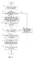
- FIG. 3 is a control flowchart according to a first embodiment of this invention.
- FIG. 4 is a control flowchart according to a second embodiment of this invention.
- a clutch control device is applied to a friction clutch mechanism such as that shown in FIG. 1 , which includes a multiple disc clutch that is connected and disconnected by driving a piston using oil pressure.
- the basic constitution of the clutch control device may be identical to that of the device described in JP2006-336806A , published by the Japan Patent Office in 2006, for example.
- the friction clutch mechanism 1 is of a multiplate wet clutch type which transmits or interrupts transmission of a driving force input from an engine (internal combustion engine), not shown, between a hollow input shaft 2 and a hollow output shaft 5.
- the friction clutch mechanism 1 is constituted by a plurality of drive plates 2a, a plurality of driven plates 5a, a friction material 5b, a clutch piston 3, and a return spring 4. It should be noted that in FIG. 1 , only a cross-section on an upper half of a rotary axis CL is shown.
- the plurality of drive plates (first rotary elements) 2a are fitted to be capable of sliding in the direction of the rotary axis CL on an inner peripheral surface of the input shaft 2.
- the drive plates 2a rotate integrally with the input shaft 2 about the rotary axis CL as a central axis. Further, the driving force transmitted from the input shaft 2 is transmitted to the output shaft 5 side via the drive plates 2a.
- the driven plates (second rotary elements) 5a are provided to stand parallel to the drive plates 2a.
- the plurality of driven plates 5a are fitted to be capable of sliding in the direction of the rotary axis CL on an outer peripheral surface of the output shaft 5, and rotate integrally with the output shaft 5 about the rotary axis CL.
- the friction material 5b is adhered to a front surface of the driven plate 5a. Hence, when the drive plate 2a contacts the friction material 5b on the driven plate 5a, power transmission from the input shaft 2 side to the output shaft 5 side is caused to occur by frictional resistance.
- the clutch piston 3 is provided to be capable of sliding relative to the input shaft 2 and drive plates 2a in the direction of the rotary axis CL. Further, a hydraulic chamber 8 is formed on one end surface side of the clutch piston 3. The clutch piston 3 is pressed so as to slide in the rotary axis CL direction by an oil pressure of working oil supplied to the hydraulic chamber 8 via a working oil passage 9.
- the clutch piston 3 is set to move further toward the drive plate 2a side (a direction A in FIG. 1 ) as the magnitude of the oil pressure of the supplied working oil increases. Further, when the clutch piston 3 impinges on the drive plate 2a, the drive plate 2a is pressed in the direction A of FIG. 1 in accordance with the magnitude of the oil pressure of the working oil.
- the return spring 4 is interposed between the clutch piston 3 and the input shaft 2 such that the clutch piston 3 is biased in a direction B of FIG. 1 .
- a biasing force of the return spring 4 is set such that a clearance (gap) of a predetermined distance d is maintained between the clutch piston 3 and the drive plate 2a when the oil pressure of the working oil supplied through the working oil passage 9 is lower than a first predetermined pressure.
- the predetermined distance d is a separation distance between the clutch piston 3 and the drive plate 2a when the clutch piston 3 has slid as far as possible in the direction B of FIG. 1 .
- the position of the clutch piston 3 when a gap having the predetermined distance d is maintained as the clearance between the clutch piston 3 and the drive plate 2a will be referred to hereafter as a reference position, and movement of the clutch piston 3 in the direction of the drive plate 2a (the direction A in FIG. 1 ) will be referred to as a stroke.
- a load of the return spring 4 in the reference position will be referred to as a return spring set load.
- the stroke of the clutch piston 3 is zero, the clearance to the drive plate 2a corresponds to the predetermined distance d.
- the clutch piston 3 contacts the drive plate 2a, whereby a so-called half clutch state (a clutch slip state) is achieved such that power transmission from the input shaft 2 side to the output shaft 5 side begins.
- the clutch control device of this embodiment is applied to the friction clutch mechanism 1 described above.
- the clutch control device is constituted by an oil pressure adjustment device 7 that adjusts the oil pressure of the working oil supplied to the hydraulic chamber 8, an oil pressure sensor 6 that detects the magnitude of the oil pressure of the working oil flowing through the working oil passage 9, and an electronic control device (ECU) 10 that controls the oil pressure adjustment device 7.
- ECU electronic control device
- the working oil flowing through the working oil passage 9 is supplied from a hydraulic pump (not shown).
- the oil pressure adjustment device 7 includes a solenoid valve serving as a control valve for adjusting the oil pressure of the working oil supplied to the hydraulic chamber 8 through the working oil passage 9, and is used to control a working oil supply from the hydraulic pump on the basis of an oil pressure control signal (command value) from the ECU 10 such that the oil pressure of the working oil supplied to the hydraulic chamber 8 can be increased and decreased.
- a solenoid valve serving as a control valve for adjusting the oil pressure of the working oil supplied to the hydraulic chamber 8 through the working oil passage 9, and is used to control a working oil supply from the hydraulic pump on the basis of an oil pressure control signal (command value) from the ECU 10 such that the oil pressure of the working oil supplied to the hydraulic chamber 8 can be increased and decreased.
- the oil pressure sensor 6 is interposed on the working oil passage 9 in the vicinity of the clutch piston 3, and is used to detect the oil pressure magnitude (in other words, an actual oil pressure) of the working oil acting on the clutch piston 3 and output the detected actual oil pressure to the ECU 10.
- the actual oil pressure is the magnitude of the oil pressure that actually acts on the clutch piston 3, and not the magnitude of the oil pressure adjusted by the oil pressure adjustment device 7.
- the magnitude of the oil pressure adjusted by the oil pressure adjustment device 7 is detected by the oil pressure sensor 6, whereas in a non-steady state where the clutch piston 3 is mobile, an oil pressure having a different value to the oil pressure adjusted by the oil pressure adjustment device 7 is detected in the oil pressure sensor 6.
- the ECU 10 is constituted by a central processing unit (CPU), a random access memory (RAM), a read-only memory (ROM), an input/output interface, and so on.
- CPU central processing unit
- RAM random access memory
- ROM read-only memory
- the ECU 10 is provided with a base oil pressure command unit 11 that outputs a basic oil pressure signal, a cycle oil pressure command unit (applying means) 12 that outputs an auxiliary oil pressure signal, an oil pressure command unit 14 that controls the oil pressure adjustment device 7 in accordance with the oil pressure signals, a stroke determination unit (stroke determining means) 13 that determines a stroke of the clutch piston 3, a learning unit (learning means) 15 that learns the determined stroke, and a storage unit (storage means) 16 that stores the learned content, as function elements.
- a base oil pressure command unit 11 that outputs a basic oil pressure signal
- a cycle oil pressure command unit (applying means) 12 that outputs an auxiliary oil pressure signal
- an oil pressure command unit 14 that controls the oil pressure adjustment device 7 in accordance with the oil pressure signals
- a stroke determination unit (stroke determining means) 13 that determines a stroke of the clutch piston 3
- learning unit learning means
- storage means 16 that stores the learned content, as function elements.
- the oil pressure command unit 14 functions to adjust the oil pressure of the working oil supplied to the hydraulic chamber 8 by outputting a command oil pressure (a value proportionate to an electric current command value issued to the solenoid valve) to the oil pressure adjustment device 7 in accordance with the magnitude of the oil pressure signals input by the base oil pressure command unit 11 and cycle oil pressure command unit 12 in order to control the oil pressure adjustment device 7.
- a command oil pressure (a value proportionate to an electric current command value issued to the solenoid valve)
- Temporal variation in the command oil pressure is shown by a solid line in FIG. 2 .
- the base oil pressure command unit 11 has a function for outputting the basic oil pressure signal to the oil pressure command unit 14.
- the basic oil pressure signal is an oil pressure signal used for detecting the stroke of the clutch piston 3, the value of which increases gradually over time.
- the cycle oil pressure command unit (applying means) 12 has a function for outputting the auxiliary oil pressure signal (wave signal) to the oil pressure command unit 14.
- the auxiliary oil pressure signal is also an oil pressure signal used for detecting the stroke of the clutch piston 3, and takes the form of a pulse signal having a predetermined period and a predetermined amplitude.
- a pulse signal is used in this embodiment, an alternating current signal which varies such that a current value and a voltage value thereof draw a sine curve, for example, may be used.
- the pulse signal output from the cycle oil pressure command unit 12 is applied to the basic oil pressure signal output from the base oil pressure command unit 11, whereupon control of the oil pressure adjustment device 7 is implemented by the oil pressure command unit 14 in accordance with an oil pressure signal obtained by adding together the basic oil pressure signal and the pulse signal.
- the amplitude of the pulse signal is set such that it can be detected by the oil pressure sensor 6, and is set to be considerably smaller than that of the basic oil pressure signal. Thus, the pulse signal does not cause a driver to experience an unpleasant sensation.
- the stroke determination unit (stroke determining means) 13 determines the stroke of the clutch piston 3 on the basis of a variation amount in the magnitude of the actual oil pressure input from the oil pressure sensor 6 and a variation width of the pulse signal commanded by the cycle oil pressure command unit 12 (in other words, the amplitude of the command oil pressure).
- the stroke determination unit 13 calculates a variation Pa in the magnitude of the actual oil pressure detected by the oil pressure sensor 6 and an oil pressure magnitude Pb corresponding to the amplitude of the pulse signal from the cycle oil pressure command unit 12.
- the stroke determination unit 13 calculates an oil pressure variation ratio (Pa/Pb) between the amplitude of the actual oil pressure (variation in the magnitude of the actual oil pressure) Pa and the amplitude of the command oil pressure (variation in the oil pressure defined by the pulse signal) Pb.
- the stroke determination unit 13 determines that the stroke of clutch piston 3 has begun.
- a first predetermined ratio H1 which is smaller than a preset value of 1
- the stroke determination unit 13 determines that the stroke of clutch piston 3 has begun.
- the variation Pa in the actual oil pressure detected by the oil pressure sensor 6 decreases during the stroke of the clutch piston 3, and therefore the oil pressure variation ratio decreases greatly.
- the stroke determination unit 13 determines that the stroke of the clutch piston 3 is complete.
- the amplitude of the actual oil pressure can be detected by means of a normal method, i.e. by extracting an oscillation component (alternating current component) of the actual oil pressure signal output by the oil pressure sensor 6 in a hardware or software constitution using an electric circuit, a Fourier transform, or similar.
- the oil pressure command unit 14 is caused to terminate control of the oil pressure adjustment device 7.
- the learning unit (learning means) 15 learns the command oil pressure input into the oil pressure adjustment device 7 at the start and end of the stroke or a value obtained by removing an oscillation component (a part corresponding to the wave signal) from the command oil pressure.
- the learned command oil pressure at the start of the stroke (stroke start command oil pressure) and the learned command oil pressure at the end of the stroke (stroke end command oil pressure) are stored in the storage unit 16 and referred to for use when start-up control and shift control are implemented in the friction clutch mechanism 1.
- learning control This series of control processes executed by the ECU 10 from issuance of the oil pressure command to learning will be referred to as learning control.
- a condition for performing learning (a learning condition) is set in the learning unit 15 to improve the learning precision of the learning control.
- the learning condition is satisfied when the stroke start command oil pressure is within an appropriate range (corresponding to a step S2 to be described below) and when the stroke end command oil pressure is within an appropriate range (corresponding to a step S5 to be described below).
- the stroke start command oil pressure and stroke end command oil pressure are both within their respective appropriate ranges, the stroke end command oil pressure is learned.
- a design value P set of a stroke end actual oil pressure is expressed by the following Formula (1).
- P set P 0 + kd
- Po is a design value of the return spring set load (represented here by a pressure obtained by dividing the load of the return spring 4 by a piston sectional area)
- k is a value obtained by dividing a spring constant of the return spring by the piston sectional area
- d is a design value of the clearance.
- the piston sectional area is the sectional area of a perpendicular piston cross-section to the rotary axis CL.
- a stroke end command oil pressure P com taking into account variation in the return spring set load and variation in the clearance is expressed by the following Formula (2).
- P com P 0 + ⁇ ⁇ P 0 + k ⁇ d + ⁇ d
- ⁇ P 0 is a deviation from the set value of the return spring set load
- ⁇ d is a deviation from the set value of the clearance
- a stroke end command oil pressure P fin is expressed by the following formula (3A) or (3B).
- A P set + ⁇ ⁇ P 0 + k ⁇ d + ⁇ P set + ⁇ 3 ⁇ B
- ⁇ is a deviation of a proportional factor of a solenoid valve characteristic (a relationship between the command oil pressure and the actual oil pressure) from 1, and ⁇ is an offset of the solenoid valve characteristic.
- P fin P com
- the deviation from the ideal state is generated by deviation in the current-oil pressure characteristic of the solenoid valve and hysteresis thereof, oil temperature variation, and so on.
- P fin max of the appropriate range of the stroke end command oil pressure is set as follows.
- P fin max P set + ⁇ ⁇ P 0 max + k ⁇ ⁇ d max + ⁇ ⁇ ⁇ max P set + ⁇ ⁇ ⁇ max
- maximum values ⁇ P 0 max , ⁇ d man , ⁇ max of the respective deviations and a maximum value ⁇ max of the offset are normally larger than zero ( ⁇ P 0 max , ⁇ d max , ⁇ max , ⁇ max > 0).
- P fin min P set + ⁇ ⁇ P 0 min + k ⁇ ⁇ d min + ⁇ ⁇ ⁇ min P set + ⁇ ⁇ ⁇ min
- the maximum value and minimum value ⁇ P 0 max , ⁇ P 0 min of the deviation in the return spring set load are determined in advance as tolerances when incorporating the return spring into the clutch.
- the maximum value and minimum value ⁇ d max , ⁇ d min of the deviation from the set value of the clearance are also determined in advance as tolerances.
- the maximum value ⁇ max and minimum value ⁇ min of the deviation of the proportional factor of the solenoid valve characteristic and the maximum value ⁇ max and minimum value ⁇ min of the offset are determined in advance through experiment or the like.
- a stroke start command oil pressure P start is obtained by removing the items k (d + ⁇ d) and kd generated by the stroke of the piston from Formula (3A) such that the following Formula (5) is obtained.
- P start P 0 + ⁇ ⁇ P 0 + ⁇ ⁇ P 0 + ⁇
- P start max of the appropriate range of the stroke start command oil pressure is set as follows.
- P start max P 0 + ⁇ ⁇ P 0 max + ⁇ ⁇ ⁇ max P 0 + ⁇ ⁇ ⁇ max
- P start min P 0 + ⁇ ⁇ P 0 min + ⁇ ⁇ ⁇ min P 0 + ⁇ ⁇ ⁇ min
- a variation width of the stroke start command oil pressure is expressed by the following Formula (6).
- the stroke end command oil pressure P fin can be estimated on the basis of the stroke start command oil pressure P start , as shown in Formula (7). Therefore, in contrast to the typical case shown in Formula (3B), the appropriate range of the stroke end command oil pressure can be determined taking into consideration only two variation factors (variation in the proportional factor and variation in the clearance).
- an upper limit value D of the appropriate range of the stroke end command oil pressure is calculated as shown in the following Formula (8).
- the upper limit value D is calculated on the basis of the measured stroke start command oil pressure P start from the value k obtained by dividing the spring constant of the return spring by the piston sectional area, the design value d of the clearance, the maximum value ⁇ d max of the deviation from the set value of the clearance, and the maximum value ⁇ max of the deviation in the proportional factor of the solenoid valve characteristic, taking into account only two variation factors, namely the deviation of the proportional factor and the deviation of the clearance.
- a lower limit value C of the appropriate range of the stroke end command oil pressure is calculated as shown in the following Formula (9).
- the lower limit value C is calculated on the basis of the measured stroke start command oil pressure P start from the value k obtained by dividing the spring constant of the return spring by the piston sectional area, the design value d of the clearance, the minimum value ⁇ d min of the deviation from the set value of the clearance, and the minimum value ⁇ min of the deviation in the proportional factor of the solenoid valve characteristic, taking into account only two variation factors, namely the deviation of the proportional factor and the deviation of the clearance.
- the variation width ⁇ P fin of the stroke end command oil pressure is expressed by the following Formula (10).
- the stroke end command oil pressure P fin is estimated on the basis of the stroke start command oil pressure P start . Therefore, in contrast to the typical case shown in Formula (4), only two variation factors, namely variation in the proportional factor and variation in the clearance, need be taken into account. As a result, the appropriate range of the stroke end command oil pressure is determined with a high degree of precision, and accordingly, the learning condition becomes stricter, leading to an improvement in the accuracy of the learned value of the stroke end command oil pressure.
- the appropriate range of the stroke end command oil pressure is determined with a high degree of precision without the need to take into account variation from the set value of the return spring set load and variation in the offset of the solenoid valve characteristic, and therefore the precision of the learned value of the stroke end command oil pressure improves.
- a clutch stroke width SW is expressed by the following Formula (11) using Formula (7).
- an upper limit value B of an appropriate range of the clutch stroke width SW is as shown in the following Formula (12).
- a lower limit value A of the appropriate range of the clutch stroke width SW is as shown in the following Formula (13).
- the appropriate range of the clutch stroke width is determined with a high degree of precision. Accordingly, when a learning condition relating to the clutch stroke width SW is used, the learning condition of the stroke end command oil pressure becomes stricter, and therefore the accuracy of the learned value of the stroke end command oil pressure improves. In other words, the appropriate range of the clutch stroke width is determined with a high degree of precision without the need to take into account variation from the set value of the return spring set load and variation in the offset of the solenoid valve characteristic. Therefore the precision of the learned value of the stroke end command oil pressure improves.
- the clutch control device implements learning control in accordance with a control flowchart shown in FIG. 3 .
- This control flow is executed repeatedly in the interior of the ECU 10 at appropriate predetermined intervals.
- a step S1 the clutch stroke start command oil pressure is detected.
- the detection method described above is employed such that a value obtained by removing the oscillation component (the part corresponding to the wave signal) from the command oil pressure is detected as the clutch stroke start command oil pressure, when the oil pressure variation ratio (Pa/Pb) decreases below the first predetermined ratio H1. It should be noted that if the oscillation component is small, the command oil pressure itself may be detected as the clutch stroke start command oil pressure when the oil pressure variation ratio (Pa/Pb) decreases below the first predetermined ratio H1.
- a step S3 the lower limit value C and upper limit value D of the stroke end command oil pressure are calculated on the basis of the measured stroke start command oil pressure P start using Formulae (8) and (9).
- a step S4 the clutch stroke end command oil pressure is detected.
- the detection method described above is employed such that a value obtained by removing the oscillation component from the command oil pressure is detected as the clutch stroke end command oil pressure, when the oil pressure variation ratio (Pa/Pb) increases again so as to reach or exceed the second predetermined ratio H2. It should be noted that if the oscillation component is small, the command oil pressure itself may be detected as the clutch stroke end command oil pressure when the oil pressure variation ratio (Pa/Pb) reaches or exceeds the second predetermined ratio H2.
- step S5 a determination is made as to whether or not the detected clutch stroke end command oil pressure is between the lower limit value C and the upper limit value D.
- the clutch stroke end command oil pressure is smaller than the lower limit value C or larger than the upper limit value D, the clutch oil pressure learning control is terminated and a flag indicating an abnormal termination of the clutch oil pressure learning is set in a step S9.
- the clutch stroke end command oil pressure is between the lower limit value C and the upper limit value D, the value of the clutch stroke end command oil pressure is determined to be normal and the routine advances to a step S6.
- the clutch stroke end command oil pressure is stored.
- the clutch stroke start command oil pressure may be stored simultaneously.
- the current clutch stroke width SW is calculated.
- the clutch stroke width takes a value (P fin - P start )/k that is obtained by dividing a value obtained by subtracting the clutch stroke start command oil pressure from the clutch stroke end command oil pressure by k (the value obtained by dividing the spring constant of the return spring by the piston sectional area).
- Variation in the clutch stroke width is determined by subtracting an initial value of the clutch stroke width from the current value of the clutch stroke width.
- the initial value of the clutch stroke width is a value obtained at the start of use of the clutch.
- a step S8 the variation in the clutch stroke width is stored as a clutch wear amount.
- the variation in the clutch stroke width equals or exceeds a predetermined value, it is determined that wear has occurred on the clutch, and therefore appropriate processing such as indicating that the clutch is worn is executed by using an indicator or the like (not shown).
- the clutch stroke end command oil pressure is learned because the value of the clutch stroke end command oil pressure is normal, causing the clutch stroke width to be within the appropriate range.
- the step S3 of FIG. 3 is omitted, and instead, the clutch stroke width is calculated in a step S 15.
- the clutch stroke width SW takes a value (P fin - P start )/k obtained by dividing a value obtained by subtracting the clutch stroke start command oil pressure detected in the step S1 from the clutch stroke end command oil pressure detected in the step S4 by k (the value obtained by dividing the spring constant of the return spring by the piston sectional area).
- a determination is then made as to whether or not the clutch stroke width SW is between the lower limit value A and the upper limit value B.
- an oil pressure difference (P fin - P start ) obtained by subtracting the clutch stroke start command oil pressure detected in the step S1 from the clutch stroke end command oil pressure detected in the step S4, may be determined as an index of the clutch stroke width SW and a determination may be made as to whether or not this value is between a lower limit value kA and an upper limit value kB.
- the clutch stroke start command oil pressure and stroke end command oil pressure are detected in accordance with the oil pressure variation ratio (Pa/Pb), but detection of the clutch stroke start command oil pressure and end command oil pressure is not limited thereto, and may be performed using another method (a method described in Japanese Patent No. 2595812 , for example).
- the friction clutch mechanism 1 is described as a multiplate wet clutch, but the clutch to which the clutch control device according to the embodiments may be applied is not limited thereto, and the clutch control device may be applied to any clutch that is connected and disconnected by driving a piston using a working fluid supplied via a fluid pressure circuit, for example.
- This invention may be used as a clutch control device and a clutch control method for a vehicle.
Landscapes
- Physics & Mathematics (AREA)
- Fluid Mechanics (AREA)
- Engineering & Computer Science (AREA)
- General Engineering & Computer Science (AREA)
- Mechanical Engineering (AREA)
- Hydraulic Clutches, Magnetic Clutches, Fluid Clutches, And Fluid Joints (AREA)
Abstract
Description
- This invention relates to a clutch control device and a clutch control method.
-
JP2006-336806A - This clutch control device applies an auxiliary fluid pressure signal to a fluid pressure signal defining the magnitude of a fluid pressure of a working fluid, and then determines and learns a piston control oil pressure (command oil pressure) at the start and end of a piston stroke on the basis of variation in the magnitude of an actual fluid pressure of the working fluid generated by the auxiliary fluid pressure signal.
- However, in this prior art, when the oil pressure at the end of the clutch stroke takes an unfeasible abnormal value, this value is learned as is, and hence there is room for improvement in the learning precision.
- This invention has been invented to solve the problem described above, and an object thereof is to learn a control oil pressure of a piston at the start and end of a stroke with a high degree of accuracy.
- According to this invention, a clutch control device that controls a clutch by driving a piston using a working fluid, comprises: stroke start determining means for determining that a stroke of the piston has started and detecting a stroke start oil pressure at that time; stroke end determining means for determining that the stroke of the piston is complete and detecting a stroke end oil pressure at that time; stroke end range estimating means for estimating a range of the stroke end oil pressure from the stroke start oil pressure detected by the stroke start determining means; and learning means for learning the stroke end oil pressure detected by the stroke end determining means when the stroke end oil pressure is within the estimated range of the stroke end oil pressure.
- Further, according to this invention, a clutch control device that controls a clutch by driving a piston using a working fluid, comprises: stroke start determining means for determining that a stroke of the piston has started and detecting a stroke start oil pressure at that time; stroke end determining means for determining that the stroke of the piston is complete and detecting a stroke end oil pressure at that time; clutch stroke width calculating means for calculating a clutch stroke width from the stroke start oil pressure and the stroke end oil pressure; and learning means for learning the stroke end oil pressure detected by the stroke end determining means when the clutch stroke width is within a predetermined range.
- According to this invention, the range of the stroke end oil pressure is estimated using the stroke start oil pressure as a reference, and when the stroke end oil pressure is within the estimated range of the stroke end oil pressure, the stroke end oil pressure is learned. Hence, the learning precision of the stroke end oil pressure can be improved. Moreover, learning is performed when the clutch stroke width satisfies a predetermined condition, and therefore the learning precision can be improved.
-
FIG. 1 is a schematic diagram showing a clutch control device according to this invention. -
FIG. 2 is a time chart showing a target oil pressure (command oil pressure) (solid line) and an actual oil pressure (dotted line) when a piston of a clutch is driven according to this invention. -
FIG. 3 is a control flowchart according to a first embodiment of this invention. -
FIG. 4 is a control flowchart according to a second embodiment of this invention. - A clutch control device according to a first embodiment is applied to a friction clutch mechanism such as that shown in
FIG. 1 , which includes a multiple disc clutch that is connected and disconnected by driving a piston using oil pressure. The basic constitution of the clutch control device may be identical to that of the device described inJP2006-336806A - The
friction clutch mechanism 1 is of a multiplate wet clutch type which transmits or interrupts transmission of a driving force input from an engine (internal combustion engine), not shown, between ahollow input shaft 2 and ahollow output shaft 5. Thefriction clutch mechanism 1 is constituted by a plurality ofdrive plates 2a, a plurality of drivenplates 5a, afriction material 5b, aclutch piston 3, and areturn spring 4. It should be noted that inFIG. 1 , only a cross-section on an upper half of a rotary axis CL is shown. - The plurality of drive plates (first rotary elements) 2a are fitted to be capable of sliding in the direction of the rotary axis CL on an inner peripheral surface of the
input shaft 2. Thedrive plates 2a rotate integrally with theinput shaft 2 about the rotary axis CL as a central axis. Further, the driving force transmitted from theinput shaft 2 is transmitted to theoutput shaft 5 side via thedrive plates 2a. - Meanwhile, the driven plates (second rotary elements) 5a are provided to stand parallel to the
drive plates 2a. The plurality of drivenplates 5a are fitted to be capable of sliding in the direction of the rotary axis CL on an outer peripheral surface of theoutput shaft 5, and rotate integrally with theoutput shaft 5 about the rotary axis CL. - The
friction material 5b is adhered to a front surface of the drivenplate 5a. Hence, when thedrive plate 2a contacts thefriction material 5b on the drivenplate 5a, power transmission from theinput shaft 2 side to theoutput shaft 5 side is caused to occur by frictional resistance. - The
clutch piston 3 is provided to be capable of sliding relative to theinput shaft 2 anddrive plates 2a in the direction of the rotary axis CL. Further, ahydraulic chamber 8 is formed on one end surface side of theclutch piston 3. Theclutch piston 3 is pressed so as to slide in the rotary axis CL direction by an oil pressure of working oil supplied to thehydraulic chamber 8 via a workingoil passage 9. - In this embodiment, the
clutch piston 3 is set to move further toward thedrive plate 2a side (a direction A inFIG. 1 ) as the magnitude of the oil pressure of the supplied working oil increases. Further, when theclutch piston 3 impinges on thedrive plate 2a, thedrive plate 2a is pressed in the direction A ofFIG. 1 in accordance with the magnitude of the oil pressure of the working oil. - Further, the
return spring 4 is interposed between theclutch piston 3 and theinput shaft 2 such that theclutch piston 3 is biased in a direction B ofFIG. 1 . In this embodiment, a biasing force of thereturn spring 4 is set such that a clearance (gap) of a predetermined distance d is maintained between theclutch piston 3 and thedrive plate 2a when the oil pressure of the working oil supplied through the workingoil passage 9 is lower than a first predetermined pressure. The predetermined distance d is a separation distance between theclutch piston 3 and thedrive plate 2a when theclutch piston 3 has slid as far as possible in the direction B ofFIG. 1 . - In other words, when power is not to be transmitted from the
input shaft 2 side to theoutput shaft 5 side, the oil pressure of the working oil is reduced below the first predetermined pressure, whereby theclutch piston 3 is biased in the direction B ofFIG. 1 by the biasing force of thereturn spring 4 such that a clearance having the predetermined distance d can be provided between theclutch piston 3 and thedrive plate 2a. - Here, the position of the
clutch piston 3 when a gap having the predetermined distance d is maintained as the clearance between theclutch piston 3 and thedrive plate 2a, will be referred to hereafter as a reference position, and movement of theclutch piston 3 in the direction of thedrive plate 2a (the direction A inFIG. 1 ) will be referred to as a stroke. Further, a load of thereturn spring 4 in the reference position will be referred to as a return spring set load. Furthermore, when the stroke of theclutch piston 3 is zero, the clearance to thedrive plate 2a corresponds to the predetermined distance d. When the stroke equals d, theclutch piston 3 contacts thedrive plate 2a, whereby a so-called half clutch state (a clutch slip state) is achieved such that power transmission from theinput shaft 2 side to theoutput shaft 5 side begins. - The clutch control device of this embodiment is applied to the
friction clutch mechanism 1 described above. The clutch control device is constituted by an oil pressure adjustment device 7 that adjusts the oil pressure of the working oil supplied to thehydraulic chamber 8, anoil pressure sensor 6 that detects the magnitude of the oil pressure of the working oil flowing through the workingoil passage 9, and an electronic control device (ECU) 10 that controls the oil pressure adjustment device 7. Although not shown in the figure, the working oil flowing through the workingoil passage 9 is supplied from a hydraulic pump (not shown). - The oil pressure adjustment device 7 includes a solenoid valve serving as a control valve for adjusting the oil pressure of the working oil supplied to the
hydraulic chamber 8 through the workingoil passage 9, and is used to control a working oil supply from the hydraulic pump on the basis of an oil pressure control signal (command value) from theECU 10 such that the oil pressure of the working oil supplied to thehydraulic chamber 8 can be increased and decreased. - The
oil pressure sensor 6 is interposed on the workingoil passage 9 in the vicinity of theclutch piston 3, and is used to detect the oil pressure magnitude (in other words, an actual oil pressure) of the working oil acting on theclutch piston 3 and output the detected actual oil pressure to theECU 10. - It should be noted that the actual oil pressure is the magnitude of the oil pressure that actually acts on the
clutch piston 3, and not the magnitude of the oil pressure adjusted by the oil pressure adjustment device 7. In a steady state where theclutch piston 3 is immobile, the magnitude of the oil pressure adjusted by the oil pressure adjustment device 7 is detected by theoil pressure sensor 6, whereas in a non-steady state where theclutch piston 3 is mobile, an oil pressure having a different value to the oil pressure adjusted by the oil pressure adjustment device 7 is detected in theoil pressure sensor 6. - Next, various internal control units (control function elements) of the
ECU 10 will be described. TheECU 10 is constituted by a central processing unit (CPU), a random access memory (RAM), a read-only memory (ROM), an input/output interface, and so on. The ECU 10 is provided with a base oilpressure command unit 11 that outputs a basic oil pressure signal, a cycle oil pressure command unit (applying means) 12 that outputs an auxiliary oil pressure signal, an oilpressure command unit 14 that controls the oil pressure adjustment device 7 in accordance with the oil pressure signals, a stroke determination unit (stroke determining means) 13 that determines a stroke of theclutch piston 3, a learning unit (learning means) 15 that learns the determined stroke, and a storage unit (storage means) 16 that stores the learned content, as function elements. - The oil
pressure command unit 14 functions to adjust the oil pressure of the working oil supplied to thehydraulic chamber 8 by outputting a command oil pressure (a value proportionate to an electric current command value issued to the solenoid valve) to the oil pressure adjustment device 7 in accordance with the magnitude of the oil pressure signals input by the base oilpressure command unit 11 and cycle oilpressure command unit 12 in order to control the oil pressure adjustment device 7. Temporal variation in the command oil pressure is shown by a solid line inFIG. 2 . - The base oil
pressure command unit 11 has a function for outputting the basic oil pressure signal to the oilpressure command unit 14. The basic oil pressure signal is an oil pressure signal used for detecting the stroke of theclutch piston 3, the value of which increases gradually over time. - Meanwhile, the cycle oil pressure command unit (applying means) 12 has a function for outputting the auxiliary oil pressure signal (wave signal) to the oil
pressure command unit 14. The auxiliary oil pressure signal is also an oil pressure signal used for detecting the stroke of theclutch piston 3, and takes the form of a pulse signal having a predetermined period and a predetermined amplitude. Although a pulse signal is used in this embodiment, an alternating current signal which varies such that a current value and a voltage value thereof draw a sine curve, for example, may be used. - The pulse signal output from the cycle oil
pressure command unit 12 is applied to the basic oil pressure signal output from the base oilpressure command unit 11, whereupon control of the oil pressure adjustment device 7 is implemented by the oilpressure command unit 14 in accordance with an oil pressure signal obtained by adding together the basic oil pressure signal and the pulse signal. The amplitude of the pulse signal is set such that it can be detected by theoil pressure sensor 6, and is set to be considerably smaller than that of the basic oil pressure signal. Thus, the pulse signal does not cause a driver to experience an unpleasant sensation. - The stroke determination unit (stroke determining means) 13 determines the stroke of the
clutch piston 3 on the basis of a variation amount in the magnitude of the actual oil pressure input from theoil pressure sensor 6 and a variation width of the pulse signal commanded by the cycle oil pressure command unit 12 (in other words, the amplitude of the command oil pressure). - First, as described in
JP2006-336806A stroke determination unit 13 calculates a variation Pa in the magnitude of the actual oil pressure detected by theoil pressure sensor 6 and an oil pressure magnitude Pb corresponding to the amplitude of the pulse signal from the cycle oilpressure command unit 12. Next, thestroke determination unit 13 calculates an oil pressure variation ratio (Pa/Pb) between the amplitude of the actual oil pressure (variation in the magnitude of the actual oil pressure) Pa and the amplitude of the command oil pressure (variation in the oil pressure defined by the pulse signal) Pb. When the oil pressure variation ratio (Pa/Pb) is smaller than a first predetermined ratio H1, which is smaller than a preset value of 1, thestroke determination unit 13 determines that the stroke ofclutch piston 3 has begun. In accordance with the transmission characteristic of the actual oil pressure of the working oil, the variation Pa in the actual oil pressure detected by theoil pressure sensor 6 decreases during the stroke of theclutch piston 3, and therefore the oil pressure variation ratio decreases greatly. Further, when the oil pressure variation ratio increases again so as to reach or exceed a second predetermined ratio H2 (where H1 < H2 < 1), thestroke determination unit 13 determines that the stroke of theclutch piston 3 is complete. The amplitude of the actual oil pressure can be detected by means of a normal method, i.e. by extracting an oscillation component (alternating current component) of the actual oil pressure signal output by theoil pressure sensor 6 in a hardware or software constitution using an electric circuit, a Fourier transform, or similar. - When the
stroke determination unit 13 determines that the stroke of theclutch piston 3 is complete, the oilpressure command unit 14 is caused to terminate control of the oil pressure adjustment device 7. - From the determination result of the
stroke determination unit 13, the learning unit (learning means) 15 learns the command oil pressure input into the oil pressure adjustment device 7 at the start and end of the stroke or a value obtained by removing an oscillation component (a part corresponding to the wave signal) from the command oil pressure. The learned command oil pressure at the start of the stroke (stroke start command oil pressure) and the learned command oil pressure at the end of the stroke (stroke end command oil pressure) are stored in thestorage unit 16 and referred to for use when start-up control and shift control are implemented in the frictionclutch mechanism 1. - It should be noted that this series of control processes executed by the
ECU 10 from issuance of the oil pressure command to learning will be referred to as learning control. - Further, a condition for performing learning (a learning condition) is set in the
learning unit 15 to improve the learning precision of the learning control. Here, the learning condition is satisfied when the stroke start command oil pressure is within an appropriate range (corresponding to a step S2 to be described below) and when the stroke end command oil pressure is within an appropriate range (corresponding to a step S5 to be described below). When the stroke start command oil pressure and stroke end command oil pressure are both within their respective appropriate ranges, the stroke end command oil pressure is learned. - The appropriate range of the stroke end command oil pressure and the appropriate range of the stroke start command oil pressure will now be described.
- First, a design value Pset of a stroke end actual oil pressure is expressed by the following Formula (1).

- Here, Po is a design value of the return spring set load (represented here by a pressure obtained by dividing the load of the
return spring 4 by a piston sectional area), k is a value obtained by dividing a spring constant of the return spring by the piston sectional area, and d is a design value of the clearance. The piston sectional area is the sectional area of a perpendicular piston cross-section to the rotary axis CL. - A stroke end command oil pressure Pcom taking into account variation in the return spring set load and variation in the clearance is expressed by the following Formula (2).

- Here, ΔP0 is a deviation from the set value of the return spring set load, and Δd is a deviation from the set value of the clearance.
- Accordingly, a stroke end command oil pressure Pfin is expressed by the following formula (3A) or (3B).

- Here, Δα is a deviation of a proportional factor of a solenoid valve characteristic (a relationship between the command oil pressure and the actual oil pressure) from 1, and Δβ is an offset of the solenoid valve characteristic. In an ideal state, the stroke end command oil pressure Pfin is equal to Pcom (Pfin = Pcom), but in actuality, a deviation occurs therebetween such that Pfin = (1 + Δα) Pcom + Δβ. The deviation from the ideal state is generated by deviation in the current-oil pressure characteristic of the solenoid valve and hysteresis thereof, oil temperature variation, and so on.
- Hence, it can be seen that normally, four variation factors, namely the deviation from the set value of the return spring set load, the deviation from the set value of the clearance, the deviation in the proportional factor of the solenoid valve characteristic, and the offset of the solenoid valve characteristic, must be taken into account in relation to the appropriate range of the stroke end command oil pressure, as shown in Formula (3B).
- An upper limit value Pfin max of the appropriate range of the stroke end command oil pressure is set as follows.

- Here, maximum values ΔP0 max, Δdman, Δαmax of the respective deviations and a maximum value Δβmax of the offset are normally larger than zero (ΔP0 max, Δdmax, Δαmax, Δβmax > 0).
- Similarly, a lower limit value Pfin min of the appropriate range of the stroke end command oil pressure is set as follows.

- Here, minimum values ΔP0 min, Δdmin, Δαmin of the respective deviations and a minimum value Δβmin of the offset are normally smaller than zero (ΔP0 min, Δdmin, Δαmin, Δβmin < 0; it should be noted that normally, ΔP0 min = -ΔP0 max and Δdmin = -Δdmax).
- The maximum value and minimum value ΔP0 max, ΔP0 min of the deviation in the return spring set load are determined in advance as tolerances when incorporating the return spring into the clutch. The maximum value and minimum value Δdmax, Δdmin of the deviation from the set value of the clearance are also determined in advance as tolerances. The maximum value Δαmax and minimum value Δαmin of the deviation of the proportional factor of the solenoid valve characteristic and the maximum value Δβmax and minimum value Δβmin of the offset are determined in advance through experiment or the like.
- Hence, a variation width ΔPfin of the stroke end command oil pressure is expressed by the following Formula (4).

- Likewise with regard to the appropriate range of the stroke start command oil pressure, a stroke start command oil pressure Pstart is obtained by removing the items k (d + Δd) and kd generated by the stroke of the piston from Formula (3A) such that the following Formula (5) is obtained.

- Hence, three variation factors, namely the deviation from the set value of the return spring set load, the deviation in the proportional factor of the solenoid valve characteristic, and the offset of the solenoid valve characteristic, must be taken into account in relation to the stroke start command oil pressure.
- An upper limit value Pstart max of the appropriate range of the stroke start command oil pressure is set as follows.

- Similarly, a lower limit value Pstart min of the appropriate range of the stroke start command oil pressure is set as follows.

- Further, a variation width of the stroke start command oil pressure is expressed by the following Formula (6).

- From Formula (3A) and Formula (5), the following Formula (7) is obtained.

- In this embodiment, the stroke end command oil pressure Pfin can be estimated on the basis of the stroke start command oil pressure Pstart, as shown in Formula (7). Therefore, in contrast to the typical case shown in Formula (3B), the appropriate range of the stroke end command oil pressure can be determined taking into consideration only two variation factors (variation in the proportional factor and variation in the clearance).
- In this embodiment, an upper limit value D of the appropriate range of the stroke end command oil pressure is calculated as shown in the following Formula (8).

- Hence, the upper limit value D is calculated on the basis of the measured stroke start command oil pressure Pstart from the value k obtained by dividing the spring constant of the return spring by the piston sectional area, the design value d of the clearance, the maximum value Δdmax of the deviation from the set value of the clearance, and the maximum value Δαmax of the deviation in the proportional factor of the solenoid valve characteristic, taking into account only two variation factors, namely the deviation of the proportional factor and the deviation of the clearance.
- Furthermore, in this embodiment, a lower limit value C of the appropriate range of the stroke end command oil pressure is calculated as shown in the following Formula (9).

- Hence, the lower limit value C is calculated on the basis of the measured stroke start command oil pressure Pstart from the value k obtained by dividing the spring constant of the return spring by the piston sectional area, the design value d of the clearance, the minimum value Δdmin of the deviation from the set value of the clearance, and the minimum value Δαmin of the deviation in the proportional factor of the solenoid valve characteristic, taking into account only two variation factors, namely the deviation of the proportional factor and the deviation of the clearance.
- In this case, the variation width ΔPfin of the stroke end command oil pressure is expressed by the following Formula (10).

- Hence, in this embodiment, the stroke end command oil pressure Pfin is estimated on the basis of the stroke start command oil pressure Pstart. Therefore, in contrast to the typical case shown in Formula (4), only two variation factors, namely variation in the proportional factor and variation in the clearance, need be taken into account. As a result, the appropriate range of the stroke end command oil pressure is determined with a high degree of precision, and accordingly, the learning condition becomes stricter, leading to an improvement in the accuracy of the learned value of the stroke end command oil pressure. In other words, the appropriate range of the stroke end command oil pressure is determined with a high degree of precision without the need to take into account variation from the set value of the return spring set load and variation in the offset of the solenoid valve characteristic, and therefore the precision of the learned value of the stroke end command oil pressure improves.
- Further, a clutch stroke width SW is expressed by the following Formula (11) using Formula (7).

- Accordingly, an upper limit value B of an appropriate range of the clutch stroke width SW is as shown in the following Formula (12).

- Accordingly, a lower limit value A of the appropriate range of the clutch stroke width SW is as shown in the following Formula (13).

- In this case, variation in the clutch stroke width SW is expressed by the following Formula (14).

- Hence, with regard to the clutch stroke width SW, only two variation factors, namely deviation in the proportional factor and deviation in the clearance, need be taken into account. Therefore, similarly to the stroke end command oil pressure, the appropriate range of the clutch stroke width is determined with a high degree of precision. Accordingly, when a learning condition relating to the clutch stroke width SW is used, the learning condition of the stroke end command oil pressure becomes stricter, and therefore the accuracy of the learned value of the stroke end command oil pressure improves. In other words, the appropriate range of the clutch stroke width is determined with a high degree of precision without the need to take into account variation from the set value of the return spring set load and variation in the offset of the solenoid valve characteristic. Therefore the precision of the learned value of the stroke end command oil pressure improves.
- The clutch control device according to the first embodiment of this invention implements learning control in accordance with a control flowchart shown in
FIG. 3 . This control flow is executed repeatedly in the interior of theECU 10 at appropriate predetermined intervals. - In a step S1, the clutch stroke start command oil pressure is detected. The detection method described above is employed such that a value obtained by removing the oscillation component (the part corresponding to the wave signal) from the command oil pressure is detected as the clutch stroke start command oil pressure, when the oil pressure variation ratio (Pa/Pb) decreases below the first predetermined ratio H1. It should be noted that if the oscillation component is small, the command oil pressure itself may be detected as the clutch stroke start command oil pressure when the oil pressure variation ratio (Pa/Pb) decreases below the first predetermined ratio H1.
- In the step S2, a determination is made as to whether or not the detected clutch stroke start command oil pressure is within the appropriate range. More specifically, a determination is made as to whether or not the clutch stroke start command oil pressure Pstart is within a range extending from the predetermined maximum value Pstart max and the predetermined minimum value Pstart min.
- In a step S3, the lower limit value C and upper limit value D of the stroke end command oil pressure are calculated on the basis of the measured stroke start command oil pressure Pstart using Formulae (8) and (9).
- In a step S4, the clutch stroke end command oil pressure is detected. The detection method described above is employed such that a value obtained by removing the oscillation component from the command oil pressure is detected as the clutch stroke end command oil pressure, when the oil pressure variation ratio (Pa/Pb) increases again so as to reach or exceed the second predetermined ratio H2. It should be noted that if the oscillation component is small, the command oil pressure itself may be detected as the clutch stroke end command oil pressure when the oil pressure variation ratio (Pa/Pb) reaches or exceeds the second predetermined ratio H2.
- In the step S5, a determination is made as to whether or not the detected clutch stroke end command oil pressure is between the lower limit value C and the upper limit value D. When the clutch stroke end command oil pressure is smaller than the lower limit value C or larger than the upper limit value D, the clutch oil pressure learning control is terminated and a flag indicating an abnormal termination of the clutch oil pressure learning is set in a step S9. When the clutch stroke end command oil pressure is between the lower limit value C and the upper limit value D, the value of the clutch stroke end command oil pressure is determined to be normal and the routine advances to a step S6.
- In the step S6, the clutch stroke end command oil pressure is stored. The clutch stroke start command oil pressure may be stored simultaneously.
- In a step S7, the current clutch stroke width SW is calculated. The clutch stroke width takes a value (Pfin - Pstart)/k that is obtained by dividing a value obtained by subtracting the clutch stroke start command oil pressure from the clutch stroke end command oil pressure by k (the value obtained by dividing the spring constant of the return spring by the piston sectional area). Variation in the clutch stroke width is determined by subtracting an initial value of the clutch stroke width from the current value of the clutch stroke width. The initial value of the clutch stroke width is a value obtained at the start of use of the clutch.
- In a step S8, the variation in the clutch stroke width is stored as a clutch wear amount. When the variation in the clutch stroke width equals or exceeds a predetermined value, it is determined that wear has occurred on the clutch, and therefore appropriate processing such as indicating that the clutch is worn is executed by using an indicator or the like (not shown).
- Next, a second embodiment will be described. Learning control according to the second embodiment is implemented in accordance with a flowchart shown in
FIG. 4 . This control flow is executed repeatedly in the interior of theECU 10 at appropriate predetermined intervals. It should be noted that in the flowchart shown inFIG. 4 , identical steps to those of the flowchart shown inFIG. 3 have been allocated identical numbers, and description thereof has been omitted. - In the second embodiment, a determination is made as to whether or not the clutch stroke width, rather than the clutch stroke end command oil pressure, is within the appropriate range. When the clutch stroke width is within the appropriate range, the clutch stroke end command oil pressure is learned because the value of the clutch stroke end command oil pressure is normal, causing the clutch stroke width to be within the appropriate range.
- In the flowchart of
FIG. 4 , the step S3 ofFIG. 3 is omitted, and instead, the clutch stroke width is calculated in astep S 15. Here, the clutch stroke width SW takes a value (Pfin - Pstart)/k obtained by dividing a value obtained by subtracting the clutch stroke start command oil pressure detected in the step S1 from the clutch stroke end command oil pressure detected in the step S4 by k (the value obtained by dividing the spring constant of the return spring by the piston sectional area). A determination is then made as to whether or not the clutch stroke width SW is between the lower limit value A and the upper limit value B. When the clutch stroke width SW is smaller than the lower limit value A or larger than the upper limit value B, it is determined that the clutch stroke end command oil pressure is abnormal, and therefore learning of the clutch stroke end command oil pressure is terminated and the flag indicating an abnormal termination of the clutch oil pressure learning is set in the step S9. When the clutch stroke end command oil pressure is between the lower limit value A and the upper limit value B, the routine advances to the step S6. Since the value of the clutch stroke end command oil pressure is normal causing the clutch stroke width to be within the appropriate range, the clutch stroke end command oil pressure is stored. - In the step S15, an oil pressure difference (Pfin - Pstart) obtained by subtracting the clutch stroke start command oil pressure detected in the step S1 from the clutch stroke end command oil pressure detected in the step S4, may be determined as an index of the clutch stroke width SW and a determination may be made as to whether or not this value is between a lower limit value kA and an upper limit value kB.
- This invention is not limited to the embodiments described above, and may naturally be subjected to various modifications and improvements within the scope of the technical spirit thereof.
- For example, in the first and second embodiments described above, the clutch stroke start command oil pressure and stroke end command oil pressure are detected in accordance with the oil pressure variation ratio (Pa/Pb), but detection of the clutch stroke start command oil pressure and end command oil pressure is not limited thereto, and may be performed using another method (a method described in Japanese Patent No.
2595812 - Further, in the above embodiments, the friction
clutch mechanism 1 is described as a multiplate wet clutch, but the clutch to which the clutch control device according to the embodiments may be applied is not limited thereto, and the clutch control device may be applied to any clutch that is connected and disconnected by driving a piston using a working fluid supplied via a fluid pressure circuit, for example. - This invention may be used as a clutch control device and a clutch control method for a vehicle.
Claims (6)
- A clutch control device that controls a clutch by driving a piston (3) using a working fluid, comprising:stroke start determining means (S1) for determining that a stroke of the piston (3) has started and detecting a stroke start oil pressure at that time;stroke end determining means (S4) for determining that the stroke of the piston is complete and detecting a stroke end oil pressure at that time;stroke end range estimating means (S3) for estimating a range of the stroke end oil pressure from the stroke start oil pressure detected by the stroke start determining means; andlearning means (S5, S6) for learning the stroke end oil pressure detected by the stroke end determining means when the stroke end oil pressure is within the estimated range of the stroke end oil pressure.
- The clutch control device as defined in Claim 1, further comprising:stroke width calculating means (S7) for calculating a stroke width of the piston from the stroke start oil pressure and the stroke end oil pressure; andwear amount calculating means (S8) for calculating a clutch wear amount from temporal variation in the stroke width calculated by the stroke width calculating means.
- A clutch control device that controls a clutch by driving a piston (3) using a working fluid, comprising:stroke start determining means (S1) for determining that a stroke of the piston (3) has started and detecting a stroke start oil pressure at that time;stroke end determining means (S4) for determining that the stroke of the piston is complete and detecting a stroke end oil pressure at that time;clutch stroke width calculating means (S7) for calculating a clutch stroke width from the stroke start oil pressure and the stroke end oil pressure; andlearning means (S5, S6) for learning the stroke end oil pressure detected by the stroke end determining means when the clutch stroke width is within a predetermined range.
- The clutch control device as defined in Claim 3, further comprising wear amount calculating means (S8) for calculating a clutch wear amount from temporal variation in the clutch stroke width calculated by the clutch stroke width calculating means.
- A clutch control method for controlling a clutch by driving a piston (3) using a working fluid, comprising the steps of:determining that a stroke of the piston (3) has started and detecting a stroke start oil pressure at that time (S1);determining that the stroke of the piston is complete and detecting a stroke end oil pressure at that time (S4);estimating a range of the stroke end oil pressure from the stroke start oil pressure detected by the stroke start determining means (S3); andlearning the stroke end oil pressure detected by the stroke end determining means when the stroke end oil pressure is within the estimated range of the stroke end oil pressure (S5, S6).
- A clutch control method for controlling a clutch by driving a piston (3) using a working fluid, comprising:determining that a stroke of the piston (3) has started and detecting a stroke start oil pressure at that time (S1);determining that the stroke of the piston is complete and detecting a stroke end oil pressure at that time (S4);calculating a clutch stroke width from the stroke start oil pressure and the stroke end oil pressure (S7); andlearning the stroke end oil pressure detected by the stroke end determining means when the clutch stroke width is within a predetermined range (S5, S6).
Applications Claiming Priority (2)
| Application Number | Priority Date | Filing Date | Title |
|---|---|---|---|
| JP2007072931A JP4605169B2 (en) | 2007-03-20 | 2007-03-20 | Clutch control device and clutch control method |
| PCT/JP2008/055985 WO2008114890A1 (en) | 2007-03-20 | 2008-03-21 | Clutch control device, and clutch control method |
Publications (3)
| Publication Number | Publication Date |
|---|---|
| EP2133584A1 true EP2133584A1 (en) | 2009-12-16 |
| EP2133584A4 EP2133584A4 (en) | 2012-05-02 |
| EP2133584B1 EP2133584B1 (en) | 2013-01-02 |
Family
ID=39765989
Family Applications (1)
| Application Number | Title | Priority Date | Filing Date |
|---|---|---|---|
| EP08739114A Not-in-force EP2133584B1 (en) | 2007-03-20 | 2008-03-21 | Clutch control device, and clutch control method |
Country Status (5)
| Country | Link |
|---|---|
| US (1) | US8666624B2 (en) |
| EP (1) | EP2133584B1 (en) |
| JP (1) | JP4605169B2 (en) |
| CN (1) | CN101631962B (en) |
| WO (1) | WO2008114890A1 (en) |
Cited By (1)
| Publication number | Priority date | Publication date | Assignee | Title |
|---|---|---|---|---|
| EP2532913A4 (en) * | 2010-02-05 | 2016-05-11 | Honda Motor Co Ltd | CLUTCH CONTROL DEVICE |
Families Citing this family (9)
| Publication number | Priority date | Publication date | Assignee | Title |
|---|---|---|---|---|
| JP5153525B2 (en) * | 2008-09-01 | 2013-02-27 | 本田技研工業株式会社 | Clutch control device |
| CN103256322B (en) * | 2013-05-10 | 2016-01-27 | 浙江吉利汽车研究院有限公司杭州分公司 | Control method and device of automatic transmission clutch |
| CN103953665B (en) * | 2014-04-29 | 2017-01-11 | 吉林东光集团有限公司 | Automatic learning system and method for stroke critical value of clutch |
| US9506509B1 (en) * | 2015-09-10 | 2016-11-29 | Ford Global Technologies, Llc | Clutch control using dither |
| JP6658499B2 (en) * | 2016-12-26 | 2020-03-04 | トヨタ自動車株式会社 | Hydraulic control device for engagement mechanism |
| JP7264128B2 (en) * | 2020-08-06 | 2023-04-25 | トヨタ自動車株式会社 | Stroke amount estimation device, vehicle control device, and vehicle control system |
| US11608864B2 (en) * | 2021-03-31 | 2023-03-21 | Dana Italia S.R.L. | Hydraulic system and piston filling control |
| KR102931330B1 (en) | 2021-09-10 | 2026-02-25 | 현대자동차주식회사 | Clutch control reference value setting method |
| US12146535B2 (en) * | 2022-11-10 | 2024-11-19 | GM Global Technology Operations LLC | Clutch controls for electric vehicle transmission with modular actuation system |
Family Cites Families (22)
| Publication number | Priority date | Publication date | Assignee | Title |
|---|---|---|---|---|
| JPS6319425A (en) * | 1986-07-08 | 1988-01-27 | Isuzu Motors Ltd | Clutch controlling device |
| JP2681920B2 (en) * | 1987-04-20 | 1997-11-26 | 三菱自動車工業株式会社 | Hydraulic control device for automatic transmission |
| DE3820874A1 (en) * | 1987-06-27 | 1989-01-05 | Zahnradfabrik Friedrichshafen | Clutch device |
| JP2595812B2 (en) | 1990-11-30 | 1997-04-02 | 三菱自動車工業株式会社 | Differential adjustable front and rear wheel torque distribution control device |
| JP3307791B2 (en) * | 1995-03-02 | 2002-07-24 | 本田技研工業株式会社 | Hydraulic control device for hydraulically operated transmission for vehicle |
| JP2876109B2 (en) * | 1995-05-12 | 1999-03-31 | アイシン・エィ・ダブリュ株式会社 | Control device for automatic transmission |
| JPH09280348A (en) * | 1996-04-10 | 1997-10-28 | Komatsu Ltd | Method for detecting wear of clutch of transmission and detecting device therefor |
| JPH11247890A (en) * | 1998-02-27 | 1999-09-14 | Isuzu Motors Ltd | Method of specifying half-clutch stroke value and abnormality diagnosis method |
| EP1008503B1 (en) * | 1998-12-08 | 2009-02-25 | Hyundai Motor Company | Brake control system and method for preventing a vehicle from rolling downward on a slope |
| JP3954311B2 (en) * | 2001-01-11 | 2007-08-08 | ジヤトコ株式会社 | Shift control method and apparatus for automatic transmission |
| WO2002101258A2 (en) * | 2001-06-13 | 2002-12-19 | Luk Lamellen Und Kupplungsbau Beteiligungs Kg | Clutch actuation device and methods for determining clutch parameters |
| JP4323132B2 (en) * | 2002-03-15 | 2009-09-02 | 株式会社日立製作所 | Automobile control method, automobile control device, transmission, transmission control device, and vehicle system |
| JP2005003193A (en) * | 2003-05-16 | 2005-01-06 | Toyota Motor Corp | Control device for vehicle lock-up clutch |
| FR2855573B1 (en) | 2003-05-26 | 2006-07-14 | Renault Sa | METHOD FOR DETECTING WEAR OF A PILOT CLUTCH |
| DE502005002536D1 (en) | 2004-05-05 | 2008-03-06 | Luk Lamellen & Kupplungsbau | A method of detecting a fault of an actuator |
| US8463516B2 (en) | 2004-12-23 | 2013-06-11 | Schaeffler Technologies AG & Co. KG | Starter release |
| DE102005001523A1 (en) * | 2005-01-13 | 2006-07-27 | Zf Friedrichshafen Ag | Method for operating an automatically operable friction clutch and / or a transmission |
| JP4358130B2 (en) * | 2005-02-22 | 2009-11-04 | ジヤトコ株式会社 | Hydraulic control device for automatic transmission |
| JP4800014B2 (en) * | 2005-03-31 | 2011-10-26 | 本田技研工業株式会社 | Hydraulic circuit control device |
| JP4185922B2 (en) * | 2005-06-03 | 2008-11-26 | ジヤトコ株式会社 | Clutch control device and clutch control method |
| JP4210681B2 (en) * | 2005-10-03 | 2009-01-21 | ジヤトコ株式会社 | Control device for automatic transmission |
| US7909729B2 (en) * | 2005-10-07 | 2011-03-22 | Honda Motor Co., Ltd. | Control unit for an electric oil pump |
-
2007
- 2007-03-20 JP JP2007072931A patent/JP4605169B2/en not_active Expired - Fee Related
-
2008
- 2008-03-21 US US12/531,125 patent/US8666624B2/en not_active Expired - Fee Related
- 2008-03-21 EP EP08739114A patent/EP2133584B1/en not_active Not-in-force
- 2008-03-21 CN CN200880007715.2A patent/CN101631962B/en not_active Expired - Fee Related
- 2008-03-21 WO PCT/JP2008/055985 patent/WO2008114890A1/en not_active Ceased
Cited By (1)
| Publication number | Priority date | Publication date | Assignee | Title |
|---|---|---|---|---|
| EP2532913A4 (en) * | 2010-02-05 | 2016-05-11 | Honda Motor Co Ltd | CLUTCH CONTROL DEVICE |
Also Published As
| Publication number | Publication date |
|---|---|
| JP2008232271A (en) | 2008-10-02 |
| CN101631962B (en) | 2014-12-10 |
| WO2008114890A1 (en) | 2008-09-25 |
| CN101631962A (en) | 2010-01-20 |
| EP2133584B1 (en) | 2013-01-02 |
| US8666624B2 (en) | 2014-03-04 |
| JP4605169B2 (en) | 2011-01-05 |
| US20100250079A1 (en) | 2010-09-30 |
| EP2133584A4 (en) | 2012-05-02 |
Similar Documents
| Publication | Publication Date | Title |
|---|---|---|
| EP2133584B1 (en) | Clutch control device, and clutch control method | |
| EP2233792B1 (en) | Belt type continuously variable transmission and control method thereof | |
| KR101302329B1 (en) | Clutch control device and clutch control method | |
| KR101505224B1 (en) | Method for controlling a friction-type continuously variable transmission and a transmission equiped with means for carrying out the method | |
| EP2299145B1 (en) | Flow control method and flow controller for a continuously variable transmission | |
| US6117048A (en) | Apparatus and method for detecting abrasion of clutch for transmission | |
| US20110278129A1 (en) | Method for actuating a friction clutch | |
| CN104968959B (en) | The driving force distribution device of hydraulic pressure control device and four-wheel drive vehicle | |
| CN104220789B (en) | The coefficient of friction correcting device of variable v-belt drive | |
| US8812200B2 (en) | Method for determining an operating condition of a positively engaging shifting element of a transmission device | |
| US20200103023A1 (en) | Method for Controlling an Axial Piston Pump and Drive Unit with such an Axial Piston Pump and Hydrostatic Traction Drive with such a Drive Unit | |
| US11333239B2 (en) | Method for actuating a hydraulic system of a transmission having a variable displacement hydraulic pump | |
| EP1403563B1 (en) | Control for belt-type continuously-variable transmission | |
| US6659253B2 (en) | Method for operating a clutch and control device for implementing the method | |
| US6701241B2 (en) | Method and device for operating a clutch | |
| US6192306B1 (en) | Speed change controller for continuously variable transmission | |
| EP2520787A1 (en) | Start-clutch control device | |
| US20060148614A1 (en) | Control apparatus of automatic transmission | |
| JP2010156428A (en) | Control device of flow rate control valve | |
| US20160061320A1 (en) | Hydraulic control system for a belt-driven continuously variable transmission | |
| KR20040067922A (en) | Method and device for presetting pressing force between two frictionally engaged components of a drive system which transmit torque | |
| EP3306144A1 (en) | Control device for continuously variable transmission | |
| JPWO2016125689A1 (en) | Transmission control system | |
| EP3546800B1 (en) | Continuously variable transmission and method for controlling continuously variable transmission | |
| EP2176572B1 (en) | Method for controlling a friction-type continuously variable transmission |
Legal Events
| Date | Code | Title | Description |
|---|---|---|---|
| PUAI | Public reference made under article 153(3) epc to a published international application that has entered the european phase |
Free format text: ORIGINAL CODE: 0009012 |
|
| 17P | Request for examination filed |
Effective date: 20091002 |
|
| AK | Designated contracting states |
Kind code of ref document: A1 Designated state(s): AT BE BG CH CY CZ DE DK EE ES FI FR GB GR HR HU IE IS IT LI LT LU LV MC MT NL NO PL PT RO SE SI SK TR |
|
| DAX | Request for extension of the european patent (deleted) | ||
| A4 | Supplementary search report drawn up and despatched |
Effective date: 20120329 |
|
| RIC1 | Information provided on ipc code assigned before grant |
Ipc: F16D 48/06 20060101ALI20120323BHEP Ipc: F16D 25/12 20060101AFI20120323BHEP Ipc: F16D 48/02 20060101ALI20120323BHEP |
|
| RIC1 | Information provided on ipc code assigned before grant |
Ipc: F16D 48/02 20060101ALI20120606BHEP Ipc: F16D 48/06 20060101ALI20120606BHEP Ipc: F16D 25/12 20060101AFI20120606BHEP |
|
| GRAP | Despatch of communication of intention to grant a patent |
Free format text: ORIGINAL CODE: EPIDOSNIGR1 |
|
| GRAS | Grant fee paid |
Free format text: ORIGINAL CODE: EPIDOSNIGR3 |
|
| GRAA | (expected) grant |
Free format text: ORIGINAL CODE: 0009210 |
|
| AK | Designated contracting states |
Kind code of ref document: B1 Designated state(s): AT BE BG CH CY CZ DE DK EE ES FI FR GB GR HR HU IE IS IT LI LT LU LV MC MT NL NO PL PT RO SE SI SK TR |
|
| REG | Reference to a national code |
Ref country code: GB Ref legal event code: FG4D |
|
| REG | Reference to a national code |
Ref country code: AT Ref legal event code: REF Ref document number: 591785 Country of ref document: AT Kind code of ref document: T Effective date: 20130115 Ref country code: CH Ref legal event code: EP |
|
| REG | Reference to a national code |
Ref country code: IE Ref legal event code: FG4D |
|
| REG | Reference to a national code |
Ref country code: DE Ref legal event code: R096 Ref document number: 602008021360 Country of ref document: DE Effective date: 20130228 |
|
| REG | Reference to a national code |
Ref country code: AT Ref legal event code: MK05 Ref document number: 591785 Country of ref document: AT Kind code of ref document: T Effective date: 20130102 |
|
| REG | Reference to a national code |
Ref country code: NL Ref legal event code: VDEP Effective date: 20130102 |
|
| PG25 | Lapsed in a contracting state [announced via postgrant information from national office to epo] |
Ref country code: SI Free format text: LAPSE BECAUSE OF FAILURE TO SUBMIT A TRANSLATION OF THE DESCRIPTION OR TO PAY THE FEE WITHIN THE PRESCRIBED TIME-LIMIT Effective date: 20130102 |
|
| REG | Reference to a national code |
Ref country code: LT Ref legal event code: MG4D |
|
| PG25 | Lapsed in a contracting state [announced via postgrant information from national office to epo] |
Ref country code: NO Free format text: LAPSE BECAUSE OF FAILURE TO SUBMIT A TRANSLATION OF THE DESCRIPTION OR TO PAY THE FEE WITHIN THE PRESCRIBED TIME-LIMIT Effective date: 20130402 Ref country code: AT Free format text: LAPSE BECAUSE OF FAILURE TO SUBMIT A TRANSLATION OF THE DESCRIPTION OR TO PAY THE FEE WITHIN THE PRESCRIBED TIME-LIMIT Effective date: 20130102 Ref country code: IS Free format text: LAPSE BECAUSE OF FAILURE TO SUBMIT A TRANSLATION OF THE DESCRIPTION OR TO PAY THE FEE WITHIN THE PRESCRIBED TIME-LIMIT Effective date: 20130502 Ref country code: BG Free format text: LAPSE BECAUSE OF FAILURE TO SUBMIT A TRANSLATION OF THE DESCRIPTION OR TO PAY THE FEE WITHIN THE PRESCRIBED TIME-LIMIT Effective date: 20130402 Ref country code: SE Free format text: LAPSE BECAUSE OF FAILURE TO SUBMIT A TRANSLATION OF THE DESCRIPTION OR TO PAY THE FEE WITHIN THE PRESCRIBED TIME-LIMIT Effective date: 20130102 Ref country code: LT Free format text: LAPSE BECAUSE OF FAILURE TO SUBMIT A TRANSLATION OF THE DESCRIPTION OR TO PAY THE FEE WITHIN THE PRESCRIBED TIME-LIMIT Effective date: 20130102 Ref country code: ES Free format text: LAPSE BECAUSE OF FAILURE TO SUBMIT A TRANSLATION OF THE DESCRIPTION OR TO PAY THE FEE WITHIN THE PRESCRIBED TIME-LIMIT Effective date: 20130413 Ref country code: BE Free format text: LAPSE BECAUSE OF FAILURE TO SUBMIT A TRANSLATION OF THE DESCRIPTION OR TO PAY THE FEE WITHIN THE PRESCRIBED TIME-LIMIT Effective date: 20130102 Ref country code: CZ Free format text: LAPSE BECAUSE OF FAILURE TO SUBMIT A TRANSLATION OF THE DESCRIPTION OR TO PAY THE FEE WITHIN THE PRESCRIBED TIME-LIMIT Effective date: 20130102 |
|
| PG25 | Lapsed in a contracting state [announced via postgrant information from national office to epo] |
Ref country code: GR Free format text: LAPSE BECAUSE OF FAILURE TO SUBMIT A TRANSLATION OF THE DESCRIPTION OR TO PAY THE FEE WITHIN THE PRESCRIBED TIME-LIMIT Effective date: 20130403 Ref country code: PL Free format text: LAPSE BECAUSE OF FAILURE TO SUBMIT A TRANSLATION OF THE DESCRIPTION OR TO PAY THE FEE WITHIN THE PRESCRIBED TIME-LIMIT Effective date: 20130102 Ref country code: PT Free format text: LAPSE BECAUSE OF FAILURE TO SUBMIT A TRANSLATION OF THE DESCRIPTION OR TO PAY THE FEE WITHIN THE PRESCRIBED TIME-LIMIT Effective date: 20130502 Ref country code: LV Free format text: LAPSE BECAUSE OF FAILURE TO SUBMIT A TRANSLATION OF THE DESCRIPTION OR TO PAY THE FEE WITHIN THE PRESCRIBED TIME-LIMIT Effective date: 20130102 Ref country code: FI Free format text: LAPSE BECAUSE OF FAILURE TO SUBMIT A TRANSLATION OF THE DESCRIPTION OR TO PAY THE FEE WITHIN THE PRESCRIBED TIME-LIMIT Effective date: 20130102 Ref country code: NL Free format text: LAPSE BECAUSE OF FAILURE TO SUBMIT A TRANSLATION OF THE DESCRIPTION OR TO PAY THE FEE WITHIN THE PRESCRIBED TIME-LIMIT Effective date: 20130102 |
|
| PG25 | Lapsed in a contracting state [announced via postgrant information from national office to epo] |
Ref country code: HR Free format text: LAPSE BECAUSE OF FAILURE TO SUBMIT A TRANSLATION OF THE DESCRIPTION OR TO PAY THE FEE WITHIN THE PRESCRIBED TIME-LIMIT Effective date: 20130102 |
|
| PG25 | Lapsed in a contracting state [announced via postgrant information from national office to epo] |
Ref country code: MC Free format text: LAPSE BECAUSE OF NON-PAYMENT OF DUE FEES Effective date: 20130331 Ref country code: DK Free format text: LAPSE BECAUSE OF FAILURE TO SUBMIT A TRANSLATION OF THE DESCRIPTION OR TO PAY THE FEE WITHIN THE PRESCRIBED TIME-LIMIT Effective date: 20130102 Ref country code: SK Free format text: LAPSE BECAUSE OF FAILURE TO SUBMIT A TRANSLATION OF THE DESCRIPTION OR TO PAY THE FEE WITHIN THE PRESCRIBED TIME-LIMIT Effective date: 20130102 Ref country code: RO Free format text: LAPSE BECAUSE OF FAILURE TO SUBMIT A TRANSLATION OF THE DESCRIPTION OR TO PAY THE FEE WITHIN THE PRESCRIBED TIME-LIMIT Effective date: 20130102 Ref country code: EE Free format text: LAPSE BECAUSE OF FAILURE TO SUBMIT A TRANSLATION OF THE DESCRIPTION OR TO PAY THE FEE WITHIN THE PRESCRIBED TIME-LIMIT Effective date: 20130102 |
|
| REG | Reference to a national code |
Ref country code: CH Ref legal event code: PL |
|
| PLBE | No opposition filed within time limit |
Free format text: ORIGINAL CODE: 0009261 |
|
| STAA | Information on the status of an ep patent application or granted ep patent |
Free format text: STATUS: NO OPPOSITION FILED WITHIN TIME LIMIT |
|
| PG25 | Lapsed in a contracting state [announced via postgrant information from national office to epo] |
Ref country code: CY Free format text: LAPSE BECAUSE OF FAILURE TO SUBMIT A TRANSLATION OF THE DESCRIPTION OR TO PAY THE FEE WITHIN THE PRESCRIBED TIME-LIMIT Effective date: 20130102 |
|
| 26N | No opposition filed |
Effective date: 20131003 |
|
| PG25 | Lapsed in a contracting state [announced via postgrant information from national office to epo] |
Ref country code: IT Free format text: LAPSE BECAUSE OF FAILURE TO SUBMIT A TRANSLATION OF THE DESCRIPTION OR TO PAY THE FEE WITHIN THE PRESCRIBED TIME-LIMIT Effective date: 20130102 |
|
| REG | Reference to a national code |
Ref country code: IE Ref legal event code: MM4A |
|
| REG | Reference to a national code |
Ref country code: DE Ref legal event code: R097 Ref document number: 602008021360 Country of ref document: DE Effective date: 20131003 |
|
| PG25 | Lapsed in a contracting state [announced via postgrant information from national office to epo] |
Ref country code: CH Free format text: LAPSE BECAUSE OF NON-PAYMENT OF DUE FEES Effective date: 20130331 Ref country code: IE Free format text: LAPSE BECAUSE OF NON-PAYMENT OF DUE FEES Effective date: 20130321 Ref country code: LI Free format text: LAPSE BECAUSE OF NON-PAYMENT OF DUE FEES Effective date: 20130331 |
|
| PGFP | Annual fee paid to national office [announced via postgrant information from national office to epo] |
Ref country code: FR Payment date: 20140311 Year of fee payment: 7 |
|
| PGFP | Annual fee paid to national office [announced via postgrant information from national office to epo] |
Ref country code: GB Payment date: 20140319 Year of fee payment: 7 |
|
| PG25 | Lapsed in a contracting state [announced via postgrant information from national office to epo] |
Ref country code: MT Free format text: LAPSE BECAUSE OF FAILURE TO SUBMIT A TRANSLATION OF THE DESCRIPTION OR TO PAY THE FEE WITHIN THE PRESCRIBED TIME-LIMIT Effective date: 20130102 |
|
| PGFP | Annual fee paid to national office [announced via postgrant information from national office to epo] |
Ref country code: DE Payment date: 20140417 Year of fee payment: 7 |
|
| PG25 | Lapsed in a contracting state [announced via postgrant information from national office to epo] |
Ref country code: TR Free format text: LAPSE BECAUSE OF FAILURE TO SUBMIT A TRANSLATION OF THE DESCRIPTION OR TO PAY THE FEE WITHIN THE PRESCRIBED TIME-LIMIT Effective date: 20130102 |
|
| PG25 | Lapsed in a contracting state [announced via postgrant information from national office to epo] |
Ref country code: LU Free format text: LAPSE BECAUSE OF NON-PAYMENT OF DUE FEES Effective date: 20130321 Ref country code: HU Free format text: LAPSE BECAUSE OF FAILURE TO SUBMIT A TRANSLATION OF THE DESCRIPTION OR TO PAY THE FEE WITHIN THE PRESCRIBED TIME-LIMIT; INVALID AB INITIO Effective date: 20080321 |
|
| REG | Reference to a national code |
Ref country code: DE Ref legal event code: R119 Ref document number: 602008021360 Country of ref document: DE |
|
| GBPC | Gb: european patent ceased through non-payment of renewal fee |
Effective date: 20150321 |
|
| REG | Reference to a national code |
Ref country code: FR Ref legal event code: ST Effective date: 20151130 |
|
| PG25 | Lapsed in a contracting state [announced via postgrant information from national office to epo] |
Ref country code: DE Free format text: LAPSE BECAUSE OF NON-PAYMENT OF DUE FEES Effective date: 20151001 Ref country code: GB Free format text: LAPSE BECAUSE OF NON-PAYMENT OF DUE FEES Effective date: 20150321 |
|
| PG25 | Lapsed in a contracting state [announced via postgrant information from national office to epo] |
Ref country code: FR Free format text: LAPSE BECAUSE OF NON-PAYMENT OF DUE FEES Effective date: 20150331 |