EP2133218A2 - Radial aircraft tire - Google Patents
Radial aircraft tire Download PDFInfo
- Publication number
- EP2133218A2 EP2133218A2 EP09162057A EP09162057A EP2133218A2 EP 2133218 A2 EP2133218 A2 EP 2133218A2 EP 09162057 A EP09162057 A EP 09162057A EP 09162057 A EP09162057 A EP 09162057A EP 2133218 A2 EP2133218 A2 EP 2133218A2
- Authority
- EP
- European Patent Office
- Prior art keywords
- tire
- flipper
- bead
- reinforcement
- bead core
- Prior art date
- Legal status (The legal status is an assumption and is not a legal conclusion. Google has not performed a legal analysis and makes no representation as to the accuracy of the status listed.)
- Granted
Links
Images




Classifications
-
- B—PERFORMING OPERATIONS; TRANSPORTING
- B60—VEHICLES IN GENERAL
- B60C—VEHICLE TYRES; TYRE INFLATION; TYRE CHANGING; CONNECTING VALVES TO INFLATABLE ELASTIC BODIES IN GENERAL; DEVICES OR ARRANGEMENTS RELATED TO TYRES
- B60C15/00—Tyre beads, e.g. ply turn-up or overlap
- B60C15/06—Flipper strips, fillers, or chafing strips and reinforcing layers for the construction of the bead
-
- B—PERFORMING OPERATIONS; TRANSPORTING
- B60—VEHICLES IN GENERAL
- B60C—VEHICLE TYRES; TYRE INFLATION; TYRE CHANGING; CONNECTING VALVES TO INFLATABLE ELASTIC BODIES IN GENERAL; DEVICES OR ARRANGEMENTS RELATED TO TYRES
- B60C2200/00—Tyres specially adapted for particular applications
- B60C2200/02—Tyres specially adapted for particular applications for aircrafts
-
- Y—GENERAL TAGGING OF NEW TECHNOLOGICAL DEVELOPMENTS; GENERAL TAGGING OF CROSS-SECTIONAL TECHNOLOGIES SPANNING OVER SEVERAL SECTIONS OF THE IPC; TECHNICAL SUBJECTS COVERED BY FORMER USPC CROSS-REFERENCE ART COLLECTIONS [XRACs] AND DIGESTS
- Y10—TECHNICAL SUBJECTS COVERED BY FORMER USPC
- Y10T—TECHNICAL SUBJECTS COVERED BY FORMER US CLASSIFICATION
- Y10T152/00—Resilient tires and wheels
- Y10T152/10—Tires, resilient
- Y10T152/10495—Pneumatic tire or inner tube
- Y10T152/10765—Characterized by belt or breaker structure
- Y10T152/10783—Reinforcing plies made up from wound narrow ribbons
-
- Y—GENERAL TAGGING OF NEW TECHNOLOGICAL DEVELOPMENTS; GENERAL TAGGING OF CROSS-SECTIONAL TECHNOLOGIES SPANNING OVER SEVERAL SECTIONS OF THE IPC; TECHNICAL SUBJECTS COVERED BY FORMER USPC CROSS-REFERENCE ART COLLECTIONS [XRACs] AND DIGESTS
- Y10—TECHNICAL SUBJECTS COVERED BY FORMER USPC
- Y10T—TECHNICAL SUBJECTS COVERED BY FORMER US CLASSIFICATION
- Y10T152/00—Resilient tires and wheels
- Y10T152/10—Tires, resilient
- Y10T152/10495—Pneumatic tire or inner tube
- Y10T152/10819—Characterized by the structure of the bead portion of the tire
- Y10T152/10837—Bead characterized by the radial extent of apex, flipper or chafer into tire sidewall
Definitions
- the present invention relates to an improved radial aircraft tire. More particularly to an improved carcass structure for a radial aircraft tire.
- the radial carcass reinforcements of such tires generally comprise several plies of textile cords, which are anchored in each bead to at least one bead wire and generally have a single bead wire.
- the reinforcing elements of these reinforcements are wound around said bead wire from the inside to the outside, forming turn-ups, the respective ends of which are spaced radially from the axis of rotation of the tire.
- the severe conditions under which airplane tires are used are such that the life of the beads is short, particularly in the area of the turn-ups of the carcass reinforcement.
- the first group comprises the plies of the carcass reinforcement which are axially towards the inside in the region of the beads, these plies being then wound around a bead wire in each bead from the inside to the outside of the tire.
- the second group is formed of at least one axially outer ply in the region of the beads, which ply is generally wound around the bead wire from the outside to the inside of the tire.
- US-B- 5,769,982 shows an airplane tire having a tread, a crown reinforcement, and a radial carcass reinforcement having at least two axially inner plies of textile cords wound around a bead wire in each bead from the inside to the outside forming turn-ups and at least one axially outer ply of textile cords superimposed on the inner plies below the crown reinforcement and along the turn-ups in said beads.
- the bead wire is radially surmounted by a filler of vulcanized rubber mix having the shape of a triangle, the apex of which radially furthest from the axis of rotation is at a distance D from a straight line parallel to said axis, passing through the geometrical center of the circle circumscribed on the cross-section of the anchoring bead wire, known as the reference line.
- the tire also has at least one inner flipper wound around the bead wire to form an axially inner leg and an axially outer leg which are axially adjacent to the filler above the bead wire. The end of the axially outer leg of the inner flipper is located at a radial distance L E from the reference line such that L E is between 0.40 D and 0.80 D.
- the end of the turn-up of the inner carcass ply arranged axially furthest to the inside is located at a distance H A from the reference line such that H A is between 0.15 D and 0.50 D.
- H A is between 0.15 D and 0.50 D.
- US-B- 6,648,041 shows a flipper having both an axially inner end and an axially outer end of the flipper that extend only a distance less than the radially outermost extent of a bead filler 40 which is at a distance D as measured from the center of a bead core 30. This construction is on improvement over tires using longer flippers.
- the invention relates to a tire according to claim 1.
- the radial carcass plies are preferably made of textile reinforcing elements or cords.
- the at least one flipper reinforcement similarly, is preferably reinforced by textile reinforcing elements or cords.
- each flipper reinforcement extends along an axially inner surface of the bead core to the axially inner end located in an area that is between 0.05 BW to 0.125 BW as measured from the belt edge toward a centerline of the tire.
- the tire further has a tread radially outward of the crown reinforcement.
- each flipper reinforcement has the axially outer end located in area that is lower than the radial height of the wheel flange height of the aircraft wheel to which the tire is mounted.
- a flipper reinforcement has an axially outer end located in area that is lower than the top of the bead core.
- the tire employs two flipper reinforcements extending from the bead core to under the belt structure.
- the bead cores are formed by a plurality of sheath wires enveloping a central core that is made of a light weight metal alloy material having a weight less than steel.
- FIG. 1 a diagrammatic view in cross section of a prior art tire bead in accordance to US-B- 5,769,982 is shown.
- the example described is that of a prior art tire 10 of standard size 36 x 11.0 R 18 (standards of the Tire and Rim Association).
- the carcass reinforcement 1 is formed of five plies 1A to 1E of radial textile cords.
- Radial cords are cords which form with the circumferential direction of the tire angles which may be within the range of 90 degrees +/-10 degrees.
- three axially inner plies 1A, 1B, 1C are wound in each bead 2 around a bead wire 3 shown in the drawing as having a circular cross section, extending from the inside to the outside of the tire 10 in order to form turn-ups 10A, 10B, 10C.
- the cross section of the bead wire 3 is surmounted radially towards the outside by a strip or filler 4 of elastomeric mix having substantially the shape of a triangle, the apex A of which, radially furthest from the axis of rotation of the tire, is located at a distance D from a reference line XX'.
- the reference line is parallel to the axis of rotation and through the geometrical center O of the circle circumscribed on the cross section of the bead wire 3, which circle, in the case described, is identical with the cross section itself.
- the turn-up 10A of the inner carcass ply 1 A axially furthest towards the inside has its end spaced radially form the line XX' by the amount H A , which is equal, in the case studied, to 12 mm, namely 0.33 times the distance D, D being equal to 36 mm.
- H A the amount of the inner plies 10B and 10C, respectively. They are located radially above the apex A of the filler 4 at distances H B and H C of 55 mm and 68 mm, respectively.
- the radial end of the axially inner leg 51 of a flipper 5 which can be formed of radial textile cords identical to the carcass ply cords (but which may also be different), which end is located at a radial distance L I of 80 mm from the line XX', a distance greater than the distances H B and H C referred to above, the three ends thus arranged radially above the apex A being staggered between said apex and the point of the sidewall where the tire has a maximum axial width.
- the radial end of the axially outer leg 5E of the inner flipper 5 it is spaced from the line XX' by the radial distance L e equal to 0.58 D and greater than the distance H A .
- the two carcass plies 1D and 1E cover the turn-ups 10A, 10B, 10C of the inner carcass plies 1A to 1C axially on the outside.
- the plies 1D and 1E are wound around the bead wire 3 over a portion or circular arc corresponding to an angle at the center of the circle circumscribed on the bead wire 3 equal to at most 180 degree, so that the ends of these plies 1D and 1E are situated radially below the reference line XX'.
- the tire bead 2 is supplemented by a reinforcement ply 6 or outer chafer of radial textile cords, said ply permitting a better distribution of the pressures between the tire and its service rim, as well as assuring protection of the carcass plies against injury upon mounting.
- the axially outer end 6E of said chafer is slightly above (about 2 mm) the reference line XX', while its axially inner end 6I is below said line.
- the example shown is that of a tire of standard size 50 x 20.0 R22 (standard of the Tire and Rim Association).
- the carcass reinforcement 20 is formed of six plies 2A to 2F of radial textile cords 21.
- four axially inner plies 2A, 2B, 2C and 2D are wound in each bead 30 around a bead core 33 shown in the drawing having circular cross section.
- These four plies extend from the inside to the outside of the tire in order to form turn-ups 20A, 20B, 20C and 20D terminating at radial heights H 2A , H 2B , H 2C and H 2D respectively.
- the carcass reinforcement is radially outward of the innerliner 22 of tire 100.
- Two axially outer carcass plies 2E and 2F extend to ends 20E and 20F below bead core 33, a chipper strip 60 reinforced by cords 61 covers the ends 20E and 20F, a rubber chaffer 11 covers the chipper and extends to the sidewall rubber 9, a filler 8 and the chaffer 11 as illustrated.
- a strip or filler 40 of elastomeric material having a substantially triangular shape extending to an apex A radially furthest from the axis and located a distance D from a reference line XX'.
- the reference line is also parallel to the axis of rotation and through the geometric center O, of the circle circumscribed on the cross section of the bead core 33.
- the turn-up 20A of the inner carcass ply 2A axially furthest toward the inside has its end spaced radially from line XX' by the amount H 2A , which is, for this exemplary tire size, equal to 29 mm or 0.6 times the distance D, D being equal 48 mm.
- the tire of FIG. 2 has a nominal bead diameter N BD of 22.00 inches (558.8 mm) and a maximum section width Wh.
- the flipper 50 having ends located well below the apex A means there was an opportunity to keep the inner plies and the outer plies much closer to the optimum natural ply path.
- the cords 51 of the flipper were made equal to or smaller in diameter than the cords 21 of the plies.
- the flipper 50 which was formed of radial textile cords 51 similar to those of plies, is located with an inner end L I slightly above the height B h of the bead core 33 and an outer end L E was also shown slightly above the bead core 33.
- the ends L I , L E satisfy a relationship wherein B h ⁇ L I and L E ⁇ 0.7D as measured from the centerline XX' of the bed core 33.
- the cords 51 can be made of a diameter smaller than the ply cords 21.
- both prior art tires 10 and 100 have a flipper reinforcement that occupies a space wrapped around the bead core that prevents the axially inner plies and the axially outer plies from being closer to the optimal natural ply path as a result of the thickness of the flipper reinforcement.
- a compromise is made by the use of such flippers. This compromise means that the plies themselves in an area stressed by the beads during severe loading conditions are offset from the optimal location that one would prefer the carcass ply cords to be situated in.
- the additional endings of these flippers in this sensitive bead region reduces the durability of the tire.
- the tire 200 of an exemplary size H 37.5 x 12.0 R 19, having a 20 ply rating made according to the present invention is illustrated.
- the exemplary tire 200 has a rated load of 25,600 lbs at a pressure of 212 psi.
- the tire 200 has an air impervious inner liner 19, at least two axially inner plies, as shown three of these plies 3A, 3B and 3C extend across the crown region of the tire 200 into the bead area 80 and wrap about the bead cores 82 extending to terminal ends 30A, 30B, 30C.
- axially outer plies 3D and 3E which extend from bead to bead to ends 30D and 30E that lie basically under the bead core 82 as illustrated.
- the tire 200 further has an elastomeric filler material 8 and a chafer material 11 as shown and a sidewall material 9 covering these axially outer plies 3D and 3E.
- an optional thin green rubber layer or thin cord reinforced flipper 13 that wraps around the bead core 82. Wrapped around the thin layer 13 is a flipper reinforcement 7.
- the flipper reinforcement 7 extends from an axially inner end 71 lying between the axially outer plies 3D, 3E and the axially inner plies 3A, 3B, 3C in a region directly under a crown reinforcement 77. From this upper ending 71 of the flipper reinforcement, the flipper 7 extends radially inwardly along the sidewall of the tire 200 and wraps around the bead core 82 extending to an axially outer end 7E that is preferably well below the apex A of the bead filler 40 as illustrated. As shown in dashed lines, the wheel 202 to which the tire 200 is to be mounted has a wheel flange 204 with a radial height F H as indicated.
- the turn-up ending 7E is in the area of the wheel flange height or in the area of the wheel flange height +/-10%.
- the bead core 82 has a cross sectional length B preferably the turn-up ending 7E does not exceed a dimension that is 1.4 times the cross sectional length B of the bead core 82 as measured outwardly from the bottom of the bead core 82 perpendicular to the axis of rotation of the tire 200.
- the turn-up ending 7E of the flipper 7 is located at or below the wheel flange height F H .
- the turn-up end 7E extends radially to a height H 7E below the bead core cross sectional length B.
- the crown reinforcement 77 is formed of several belt layers 79 and has an axial maximum belt width BW as measured between the maximum width belt edges 78 of the crown reinforcement 77.
- the crown reinforcement 77 has cords 71 that are aligned at an angle between 0 and 45 degrees relative to the circumferential direction.
- Radially outward of the crown reinforcement 77 is a rubber tread 85 having a plurality of circumferential grooves 86 for water drainage.
- the ending 7I lies in the range between 0.05 and 0.125 of the belt edge 78.
- the flipper 7 extends under a belt edge 78 and wraps around the bead core 82 thereby securing both ends 7I and 7E of the flipper reinforcement enabling the flipper reinforcement 7 to become a structural member in the sidewall region of the tire 200, as such under severe loading test condition requirements wherein the tire 200 is pressurized greater than 4 times its normal rated pressure the flipper reinforcement 7 acts as an additional reinforcement added to the carcass plies and provides additional strength in the sidewall region.
- the flipper reinforcement 7 becomes a structural element in the tire 200 while reducing weight in that the flipper reinforcement 7 unlike a ply terminates under the belt edge 78 and does not extend across the crown region of the tire 200, secondarily in the bead region 80 along the axially inner side of the tire 200 there is no axially inner flipper ending there is only a terminal ending at the axially outer side of the bead 80 and this ending 7E is positioned in a strategically low region close to the bead core 82 to take the advantage of the teaching of US-B- 6,648,041 .
- This tire 200 enables that short ending 7E to avoid the region adjacent the apex A wherein the axially outer plies and turn-ups can be positioned more closely to the natural ply path of the tire 200. This creates a much smoother transition in the bead 80 and increases the durability of this particularly sensitive region of heavily loaded aircraft tires.
- the bead core 82 provided with a central core 83 of a light weight metal alloy material having a weight less than steel as taught in US-B- 6,571,847 .
- the material is aluminum or another light weight alloy and this central core 83 of the bead core 82 is then wrapped by a plurality of sheath wires 81 which envelope the central core 83, the sheath wires 81 preferably are steel cords or wires to provide strength, in this way the structural integrity of the bead core 82 is greatly enhanced relative to its weight and provides additional light weight benefits.
- the ply cords 3A through 3F are preferably an 1890 denier / 3 nylon construction, however the ply cords 3A through 3F as well as the flipper reinforcement cords can be made any known material preferably of nylon, however other materials such as aramid, polyketone, can be employed.
- An exemplary test tire 200 made according to the present invention in a size H 37.5 x 12.0 R 19 has a ply rating of 20 and a rated load of 25,600 lbs at a pressure of 212 psi.
- the tire 200 has a weight savings of 1.5 lbs per tire when compared to a prior art tire of the same size using an additional full ply with a short flipper as taught in US-B- 6,648,041 .
- the tire 200 of the present invention maintained a substantial improvement in terms of ply edge looseness in the bead regions.
- an over pressure test was conducted wherein the tires must survive an over pressure of at least 4 times the rated pressure which in the H 37.5 x 12.0 R 19 tire size is an over pressure of 848 psi minimum.
- the tire 200 according to the present invention and the prior art tire both survived the over pressure test exceeding the required 848 psi minimum.
- the tires when tested to burst pressure were remarkably almost identical in strength only differing by 2 psi and exceeding the 4 times over pressure by well over 25 percent providing a very good margin of strength.
- FIG. 5 an alternative embodiment tire 200A is shown wherein the axially outer turn-up end 7E of the flipper 7 extends to a location below the top bead core 82 as shown at or below the center of the bead core 82.
- the tire 200 according to the present invention can be made with one or more of these flippers as shown in figure 6
- an alternative embodiment tire 200B has two such flippers 7A and 7B each extending on the axially inner side from the bead core 82 to a radially outer ends7AI and 7BI under the belt edge 78.
- Each additional flipper 7B is capable of replacing a fully axially inner ply.
- each flipper 7A and 7B extends from the bead core on the axially inner side to under the belt edge 78.
- Each flipper 7A and 7B is able to replace a full axially inner ply and provide additional weight savings without sacrificing strength.
Landscapes
- Engineering & Computer Science (AREA)
- Mechanical Engineering (AREA)
- Tires In General (AREA)
Abstract
Description
- The present invention relates to an improved radial aircraft tire. More particularly to an improved carcass structure for a radial aircraft tire.
- The radial carcass reinforcements of such tires generally comprise several plies of textile cords, which are anchored in each bead to at least one bead wire and generally have a single bead wire. The reinforcing elements of these reinforcements are wound around said bead wire from the inside to the outside, forming turn-ups, the respective ends of which are spaced radially from the axis of rotation of the tire. The severe conditions under which airplane tires are used are such that the life of the beads is short, particularly in the area of the turn-ups of the carcass reinforcement.
- A substantial improvement in performance is obtained by the separating of the plies of the carcass reinforcement into two groups. The first group comprises the plies of the carcass reinforcement which are axially towards the inside in the region of the beads, these plies being then wound around a bead wire in each bead from the inside to the outside of the tire. The second group is formed of at least one axially outer ply in the region of the beads, which ply is generally wound around the bead wire from the outside to the inside of the tire. Such arrangements are described for instance in
US-B- 4,244,414 . - The life of beads formed in this manner can be improved by the presence in each bead of an additional reinforcement ply, wound around the bead wire and thus forming an axially outer leg and an axially inner leg, said reinforcement ply, also known as an inner flipper, being the ply closest to the rubber filler, radially above the anchoring bead wire. A tire structure of this type is shown in
US-B-5,285,835 . InUS-B- 5,769,982 , the life of the beads of airplane tires can be further improved, particularly when they are subjected to heavy overloads which can result in a crushing of the order of 50% and more of their height, by having the arrangement of the ends of the turned-up portions or turn-ups of the inner carcass plies and the ends of the legs of the inner flipper with respect to the radial position of the radially upper end of the rubber filler located above the anchoring bead wire and the filler. -
US-B- 5,769,982 shows an airplane tire having a tread, a crown reinforcement, and a radial carcass reinforcement having at least two axially inner plies of textile cords wound around a bead wire in each bead from the inside to the outside forming turn-ups and at least one axially outer ply of textile cords superimposed on the inner plies below the crown reinforcement and along the turn-ups in said beads. The bead wire is radially surmounted by a filler of vulcanized rubber mix having the shape of a triangle, the apex of which radially furthest from the axis of rotation is at a distance D from a straight line parallel to said axis, passing through the geometrical center of the circle circumscribed on the cross-section of the anchoring bead wire, known as the reference line. The tire also has at least one inner flipper wound around the bead wire to form an axially inner leg and an axially outer leg which are axially adjacent to the filler above the bead wire. The end of the axially outer leg of the inner flipper is located at a radial distance LE from the reference line such that LE is between 0.40 D and 0.80 D. The end of the turn-up of the inner carcass ply arranged axially furthest to the inside is located at a distance HA from the reference line such that HA is between 0.15 D and 0.50 D. Such a tire construction is shown inFig. 1 . - While this construction is durable, it limits the number of carcass plies that can be provided in the bead area and the extended length of the flipper means that the outer plies being turned down around the bead and the inner plies are spaced from the natural ply path of the tire in the region of the flipper. This spacing, while believed desirable, results in one less ply being available in the structure and in the case of very large aircraft the tire structure ideally may require the use of another ply which is effectively precluded by the use of this extended length flipper.
-
US-B- 6,648,041 shows a flipper having both an axially inner end and an axially outer end of the flipper that extend only a distance less than the radially outermost extent of abead filler 40 which is at a distance D as measured from the center of abead core 30. This construction is on improvement over tires using longer flippers. - In this application, it has been discovered that increased strength can be achieved when the flipper has one low ply turn-up end on the axially outer side of the bead wire with the other axially inner end terminating much higher than those in the prior art.
- It is an object of the present invention to provide a lightweight efficient tire structure having superb durability.
- It is a further object of the present invention to provide an improved bead structure wherein the use of inside turn-up plies and outside turndown plies is optimized by the placing of the plies close to the natural ply path.
- The invention relates to a tire according to
claim 1. - Dependent claims refer to preferred embodiments of the invention.
- The radial carcass plies are preferably made of textile reinforcing elements or cords. The at least one flipper reinforcement, similarly, is preferably reinforced by textile reinforcing elements or cords. Preferably, each flipper reinforcement extends along an axially inner surface of the bead core to the axially inner end located in an area that is between 0.05 BW to 0.125 BW as measured from the belt edge toward a centerline of the tire. The tire further has a tread radially outward of the crown reinforcement. Preferably, each flipper reinforcement has the axially outer end located in area that is lower than the radial height of the wheel flange height of the aircraft wheel to which the tire is mounted. In another alternative embodiment a flipper reinforcement has an axially outer end located in area that is lower than the top of the bead core. In a second alternative embodiment, the tire employs two flipper reinforcements extending from the bead core to under the belt structure. In a preferred embodiment the bead cores are formed by a plurality of sheath wires enveloping a central core that is made of a light weight metal alloy material having a weight less than steel.
-
- "Apex" means a preferably non-reinforced elastomer positioned radially above a bead core.
- "Aspect ratio" of the tire means the ratio of its section height (SH) to its section width (SW) multiplied by 100% for expression as percentage.
- "Axial" and "axially" means lines or directions that are parallel to the axis of rotation of the tire.
- "Bead" means that part of the tire comprising an annular tensile member wrapped by ply cords and shaped, with or without other reinforcement elements such as flippers, chippers, apexes, toe guards and chafers, to fit the design rim.
- "Carcass" means the tire structure apart form the belt structure, tread, under tread, and sidewall rubber over the plies, but including the beads.
- "Circumferential" means lines or direction extending along the perimeter of the surface of the annular tread perpendicular to the axial direction.
- "Chafers" refers to narrow strips of material placed around the outside of the bead to protect cord plies from the rim, distribute flexing above the rim, and to seal the tire.
- "Chippers" means a reinforcement structure located in the bead portion of the tire.
- "Cord" means one of the reinforcement strands which the plies in the tire comprise.
- "Equatorial plane (EP)" means the plane perpendicular to the tire's axis of rotation and passing through the center of its tread.
- "Flipper" means a preferably reinforced fabric wrapped about the bead core.
- "Normal inflation pressure" refers to the specific design inflation pressure and load assigned by the appropriate standards organization for the service condition for the tire.
- "Ply" means a continuous layer of rubber-coated parallel cords.
- "Radial" and "radially" means directions radially toward or away from the axis of rotation of the tire.
- "Radial-ply tire" means a belted or circumferentially-restricted pneumatic tire in which the ply cords which extend from bead to bead are laid at cord angles between 65 degrees and 90 degrees with respect to the equatorial plane of the tire.
- "Section height (SH)" means the radial distance from the nominal rim diameter of the tire at its equatorial plane.
- The invention will be described by way of example and with reference to the accompanying drawings in which:
-
FIG. 1 is a partial cross-sectional view of the prior art tire bead as described inUS-B- 5,769,982 . -
FIG. 2 is a partial cross sectional view of my prior art tire bead as described inUS-B- 6,648,041 . -
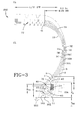
FIG. 3 is a partial cross sectional view of the tire made according to the present invention. -
FIG. 4 is a cross-sectional view of the tire ofFigure 3 . -
FIG. 5 is a partial cross-sectional view of an alternative embodiment tire made according to the present invention. -
FIG. 6 is a second alternative embodiment tire. - With reference to
FIG. 1 , a diagrammatic view in cross section of a prior art tire bead in accordance toUS-B- 5,769,982 is shown. - The example described is that of a prior art tire 10 of standard size 36 x 11.0 R 18 (standards of the Tire and Rim Association). The
carcass reinforcement 1 is formed of fiveplies 1A to 1E of radial textile cords. Radial cords, as the term is used herein, are cords which form with the circumferential direction of the tire angles which may be within the range of 90 degrees +/-10 degrees. Among these five plies, three axiallyinner plies bead 2 around abead wire 3 shown in the drawing as having a circular cross section, extending from the inside to the outside of the tire 10 in order to form turn-ups - The cross section of the
bead wire 3 is surmounted radially towards the outside by a strip orfiller 4 of elastomeric mix having substantially the shape of a triangle, the apex A of which, radially furthest from the axis of rotation of the tire, is located at a distance D from a reference line XX'. The reference line is parallel to the axis of rotation and through the geometrical center O of the circle circumscribed on the cross section of thebead wire 3, which circle, in the case described, is identical with the cross section itself. - The turn-up 10A of the inner carcass ply 1 A axially furthest towards the inside has its end spaced radially form the line XX' by the amount HA, which is equal, in the case studied, to 12 mm, namely 0.33 times the distance D, D being equal to 36 mm. As to the ends of the
inner plies 10B and 10C, respectively, they are located radially above the apex A of thefiller 4 at distances HB and HC of 55 mm and 68 mm, respectively. - The same is true of the radial end of the axially
inner leg 51 of aflipper 5, which can be formed of radial textile cords identical to the carcass ply cords (but which may also be different), which end is located at a radial distance LI of 80 mm from the line XX', a distance greater than the distances HB and HC referred to above, the three ends thus arranged radially above the apex A being staggered between said apex and the point of the sidewall where the tire has a maximum axial width. As to the radial end of the axially outer leg 5E of theinner flipper 5, it is spaced from the line XX' by the radial distance Le equal to 0.58 D and greater than the distance HA. - The two carcass plies 1D and 1E, herein called outer plies, cover the turn-
ups plies bead wire 3 over a portion or circular arc corresponding to an angle at the center of the circle circumscribed on thebead wire 3 equal to at most 180 degree, so that the ends of theseplies - The
tire bead 2 is supplemented by areinforcement ply 6 or outer chafer of radial textile cords, said ply permitting a better distribution of the pressures between the tire and its service rim, as well as assuring protection of the carcass plies against injury upon mounting. - The axially
outer end 6E of said chafer is slightly above (about 2 mm) the reference line XX', while its axially inner end 6I is below said line. - This prior art structure has been tested on a dynamometric flywheel under punishing conditions for beads of this type, these conditions corresponding to a simulation of travel on a runway (10160 kg, 4572 m, 46 km/hr), followed by a take-off from 0 to 300 km/hr, the pressure conditions being such that the crushing of the tire under the load of 10160 kg is 50% +/-2% of its height.
- Comparison with another prior art tire of the same size, 36 x 11.0
R 18, comprising the same number of carcass plies and inner and outer flipper and chafer, the inner carcass ply furthest to the inside having a turn-up end of which is located above the apex A, and the outer leg of the inner flipper having its end below said apex, clearly and unexpectedly shows the improvement, in the life of the beads, since the tires of the invention, under the above conditions, have completed on the average 35% more runway-take-off cycles. - In contrast, a
prior art tire 100 made according toUS-B- 6,648,041 is illustrated in a diagrammatic view in cross-sectionFIG. 2 . - The example shown is that of a tire of standard size 50 x 20.0 R22 (standard of the Tire and Rim Association).
- With reference to
FIG. 2 , thecarcass reinforcement 20 is formed of sixplies 2A to 2F ofradial textile cords 21. Among these six plies, four axiallyinner plies bead 30 around abead core 33 shown in the drawing having circular cross section. These four plies extend from the inside to the outside of the tire in order to form turn-ups innerliner 22 oftire 100. Two axially outer carcass plies 2E and 2F extend toends bead core 33, a chipper strip 60 reinforced by cords 61 covers theends rubber chaffer 11 covers the chipper and extends to thesidewall rubber 9, afiller 8 and thechaffer 11 as illustrated. - Outward of the
bead core 33 is a strip orfiller 40 of elastomeric material having a substantially triangular shape extending to an apex A radially furthest from the axis and located a distance D from a reference line XX'. As was shown inFIG. 1 the reference line is also parallel to the axis of rotation and through the geometric center O, of the circle circumscribed on the cross section of thebead core 33. - The turn-up 20A of the
inner carcass ply 2A axially furthest toward the inside has its end spaced radially from line XX' by the amount H2A, which is, for this exemplary tire size, equal to 29 mm or 0.6 times the distance D, D being equal 48 mm. - As shown, the tire of
FIG. 2 has a nominal bead diameter NBD of 22.00 inches (558.8 mm) and a maximum section width Wh. - The flipper 50 having ends located well below the apex A means there was an opportunity to keep the inner plies and the outer plies much closer to the optimum natural ply path. The
cords 51 of the flipper were made equal to or smaller in diameter than thecords 21 of the plies. - The flipper 50, which was formed of
radial textile cords 51 similar to those of plies, is located with an inner end LI slightly above the height Bh of thebead core 33 and an outer end LE was also shown slightly above thebead core 33. The ends LI, LE satisfy a relationship wherein Bh<LI and LE<0.7D as measured from the centerline XX' of thebed core 33. To minimize the space occupied by the flipper 50 thecords 51 can be made of a diameter smaller than theply cords 21. - As shown both
prior art tires 10 and 100 have a flipper reinforcement that occupies a space wrapped around the bead core that prevents the axially inner plies and the axially outer plies from being closer to the optimal natural ply path as a result of the thickness of the flipper reinforcement. Regardless of the diameter of thecords 51 of the flipper reinforcement it is clear that a compromise is made by the use of such flippers. This compromise means that the plies themselves in an area stressed by the beads during severe loading conditions are offset from the optimal location that one would prefer the carcass ply cords to be situated in. As can easily be appreciated the additional endings of these flippers in this sensitive bead region reduces the durability of the tire. - With reference to
Figures 3 and4 , thetire 200 of an exemplary size H 37.5 x 12.0R 19, having a 20 ply rating made according to the present invention is illustrated. Theexemplary tire 200 has a rated load of 25,600 lbs at a pressure of 212 psi. Thetire 200 has an air imperviousinner liner 19, at least two axially inner plies, as shown three of theseplies tire 200 into thebead area 80 and wrap about thebead cores 82 extending to terminal ends 30A, 30B, 30C. These terminal ends are then covered by axiallyouter plies bead core 82 as illustrated. Thetire 200 further has anelastomeric filler material 8 and achafer material 11 as shown and asidewall material 9 covering these axiallyouter plies bead core 82 is an optional thin green rubber layer or thin cord reinforcedflipper 13 that wraps around thebead core 82. Wrapped around thethin layer 13 is aflipper reinforcement 7. As shown theflipper reinforcement 7 extends from an axiallyinner end 71 lying between the axiallyouter plies inner plies crown reinforcement 77. From this upper ending 71 of the flipper reinforcement, theflipper 7 extends radially inwardly along the sidewall of thetire 200 and wraps around thebead core 82 extending to an axiallyouter end 7E that is preferably well below the apex A of thebead filler 40 as illustrated. As shown in dashed lines, thewheel 202 to which thetire 200 is to be mounted has awheel flange 204 with a radial height FH as indicated. Preferably, the turn-up ending 7E is in the area of the wheel flange height or in the area of the wheel flange height +/-10%. Thebead core 82 has a cross sectional length B preferably the turn-up ending 7E does not exceed a dimension that is 1.4 times the cross sectional length B of thebead core 82 as measured outwardly from the bottom of thebead core 82 perpendicular to the axis of rotation of thetire 200. - As shown, the turn-up ending 7E of the
flipper 7 is located at or below the wheel flange height FH. In an alternative embodiment, shown infigure 5 , the turn-upend 7E extends radially to a height H7E below the bead core cross sectional length B. - With reference to
Figure 4 , the entire cross section of thetire 200 is illustrated. As shown in the cross section, thecrown reinforcement 77 is formed of several belt layers 79 and has an axial maximum belt width BW as measured between the maximum width belt edges 78 of thecrown reinforcement 77. As shown thecrown reinforcement 77 hascords 71 that are aligned at an angle between 0 and 45 degrees relative to the circumferential direction. Radially outward of thecrown reinforcement 77 is a rubber tread 85 having a plurality ofcircumferential grooves 86 for water drainage. As shown it is important that the flipper reinforcement ending 71 below the belt layers 79 with the axially inner end extending inwardly between 0.1 BW to 0.25 BW as measured from the belt edge toward the center line of thetire 200. More preferably the ending 7I lies in the range between 0.05 and 0.125 of thebelt edge 78. In this way on each side of thetire 200, theflipper 7 extends under abelt edge 78 and wraps around thebead core 82 thereby securing both ends 7I and 7E of the flipper reinforcement enabling theflipper reinforcement 7 to become a structural member in the sidewall region of thetire 200, as such under severe loading test condition requirements wherein thetire 200 is pressurized greater than 4 times its normal rated pressure theflipper reinforcement 7 acts as an additional reinforcement added to the carcass plies and provides additional strength in the sidewall region. The advantage of this construction is that theflipper 7 does not extend across completely the crown region of thetire 200 and therefore doesn't extend very far past thebelt edge 78, this eliminates the additional weight of an additional full inner ply as was required when using short flipper reinforcements as found in my earlierprior art tire 100 as previously described. The advantages of the present invention are numerous, theflipper reinforcement 7 becomes a structural element in thetire 200 while reducing weight in that theflipper reinforcement 7 unlike a ply terminates under thebelt edge 78 and does not extend across the crown region of thetire 200, secondarily in thebead region 80 along the axially inner side of thetire 200 there is no axially inner flipper ending there is only a terminal ending at the axially outer side of thebead 80 and this ending 7E is positioned in a strategically low region close to thebead core 82 to take the advantage of the teaching ofUS-B- 6,648,041 . Thistire 200 enables that short ending 7E to avoid the region adjacent the apex A wherein the axially outer plies and turn-ups can be positioned more closely to the natural ply path of thetire 200. This creates a much smoother transition in thebead 80 and increases the durability of this particularly sensitive region of heavily loaded aircraft tires. - Another weight savings of the
tire bead core 82 provided with acentral core 83 of a light weight metal alloy material having a weight less than steel as taught inUS-B- 6,571,847 . Preferably, the material is aluminum or another light weight alloy and thiscentral core 83 of thebead core 82 is then wrapped by a plurality ofsheath wires 81 which envelope thecentral core 83, thesheath wires 81 preferably are steel cords or wires to provide strength, in this way the structural integrity of thebead core 82 is greatly enhanced relative to its weight and provides additional light weight benefits. - As shown the
ply cords 3A through 3F are preferably an 1890 denier / 3 nylon construction, however theply cords 3A through 3F as well as the flipper reinforcement cords can be made any known material preferably of nylon, however other materials such as aramid, polyketone, can be employed. - An
exemplary test tire 200 made according to the present invention in a size H 37.5 x 12.0R 19 has a ply rating of 20 and a rated load of 25,600 lbs at a pressure of 212 psi. Thetire 200 has a weight savings of 1.5 lbs per tire when compared to a prior art tire of the same size using an additional full ply with a short flipper as taught inUS-B- 6,648,041 . - When these tires were tested for endurance durability, the
tire 200 of the present invention maintained a substantial improvement in terms of ply edge looseness in the bead regions. - In a second critical comparison, an over pressure test was conducted wherein the tires must survive an over pressure of at least 4 times the rated pressure which in the H 37.5 x 12.0
R 19 tire size is an over pressure of 848 psi minimum. In this test thetire 200 according to the present invention and the prior art tire both survived the over pressure test exceeding the required 848 psi minimum. The tires when tested to burst pressure were remarkably almost identical in strength only differing by 2 psi and exceeding the 4 times over pressure by well over 25 percent providing a very good margin of strength. - In
Figure 5 , analternative embodiment tire 200A is shown wherein the axially outer turn-upend 7E of theflipper 7 extends to a location below thetop bead core 82 as shown at or below the center of thebead core 82. - The
tire 200 according to the present invention can be made with one or more of these flippers as shown infigure 6 , analternative embodiment tire 200B has twosuch flippers bead core 82 to a radially outer ends7AI and 7BI under thebelt edge 78. Eachadditional flipper 7B is capable of replacing a fully axially inner ply. - In
Figure 6 the secondalternative embodiment tire 200 is shown employing twoflippers bead core 80. In this design eachflipper belt edge 78. Eachflipper
Claims (7)
- A pneumatic radial tire for mounting on an aircraft wheel for use on an aircraft, the tire (200) comprising:a carcass comprising a pair of bead cores (82), each bead core (82) having a radially extending cross sectional length, and a number of axially inner plies (3A, 3B, 3C) greater than or equal to two extending between said bead cores (82), said carcass plies comprising textile reinforcing elements;a crown reinforcement structure (77) having one or more belt ply layers (79) or strips reinforced by cords oriented relative to the circumferential direction at an angle of between 0 degrees and 45 degrees with respect to the equatorial plane (EP) of the tire, the belt layers (79) having a maximum belt width of BW as measured between the maximum width belt edges (78) of the crown reinforcement structure (77); andat least one flipper reinforcement (7) wrapped around each bead core (82), the at least one flipper reinforcement (7) having an axially inner end (7I) and an axially outer end (7E), the axially outer end (7E) being turned up not higher than 1.4 times the cross section length (B) of bead core (82) as measured radially outwardly from bottom of the bead core perpendicular to the axis of tire rotation and wherein each flipper reinforcement (7) extends along an axially inner surface of the bead core (82) to the axially inner end (7I) located in area that is between 0.01 BW to 0.25 BW as measured from the maximum width belt edge (78) toward a centerline of the tire (200).
- The pneumatic tire of claim 1 further comprising a tread (85), the tread lying radially outward of the crown reinforcement structure (77).
- The pneumatic tire of claim 1 or 2 wherein the at least one flipper reinforcement (7) has the axially outer end (7E) located in an area that is lower than the radial height of the wheel flange height of an aircraft wheel on which the tire (200) is to be mounted in accordance with its specification.
- The pneumatic tire of at least one of the previous claims further comprising a pair of bead portions each provided therein with one of said bead cores (82), wherein the bead cores (82) are formed by a plurality of sheath wires enveloping a central core that is a light weight metal alloy material having a weight less than steel.
- The pneumatic tire of at least one of the previous claims wherein one flipper reinforcement (7) has the axially outer end (7E) located in an area that is lower than the top of the bead core (82).
- The pneumatic tire of at least one of the previous claims wherein at least one flipper reinforcement axially inner end (71) is located in an area that is 0.05 BW to 0.125 BW.
- The pneumatic tire of at least one of the previous claims comprising two flipper reinforcements (7), each flipper reinforcement (7) wrapped around each bead core (82), the flipper reinforcements (7) having an axially inner end (71) and an axially outer end (7E), the axially outer end being turned up not higher than 1.4 times the cross section length of bead core (82) as measured radially outwardly from bottom of the bead core perpendicular to the axis of tire rotation and wherein each flipper reinforcement (7) extends along an axially inner surface of the bead core (82) to the axially inner end (71) located in area that is between 0.01 BW to 0.25 BW, alternatively 0.05 BW to 0.125 BW, as measured from the maximum width belt edge (78) toward a centerline of the tire (200).
Applications Claiming Priority (1)
| Application Number | Priority Date | Filing Date | Title |
|---|---|---|---|
| US12/137,830 US8151849B2 (en) | 2008-06-12 | 2008-06-12 | Radial aircraft tire with flipper reinforcement |
Publications (3)
| Publication Number | Publication Date |
|---|---|
| EP2133218A2 true EP2133218A2 (en) | 2009-12-16 |
| EP2133218A3 EP2133218A3 (en) | 2010-07-14 |
| EP2133218B1 EP2133218B1 (en) | 2012-05-30 |
Family
ID=41076747
Family Applications (1)
| Application Number | Title | Priority Date | Filing Date |
|---|---|---|---|
| EP09162057A Active EP2133218B1 (en) | 2008-06-12 | 2009-06-05 | Radial aircraft tire |
Country Status (5)
| Country | Link |
|---|---|
| US (1) | US8151849B2 (en) |
| EP (1) | EP2133218B1 (en) |
| JP (1) | JP5746460B2 (en) |
| CN (1) | CN101602319B (en) |
| BR (1) | BRPI0902192A2 (en) |
Cited By (1)
| Publication number | Priority date | Publication date | Assignee | Title |
|---|---|---|---|---|
| EP2196327A3 (en) * | 2008-12-15 | 2012-05-30 | The Goodyear Tire & Rubber Company | Pneumatic tire |
Families Citing this family (11)
| Publication number | Priority date | Publication date | Assignee | Title |
|---|---|---|---|---|
| US9272577B2 (en) * | 2011-06-13 | 2016-03-01 | The Goodyear Tire & Rubber Company | Aircraft radial tire |
| CN102837865A (en) * | 2011-06-23 | 2012-12-26 | 林焕章 | airtight container |
| US20130056126A1 (en) * | 2011-09-06 | 2013-03-07 | Kiyoshi Ueyoko | Aircraft tire |
| US8991459B2 (en) | 2011-11-10 | 2015-03-31 | Bridgestone Americas Tire Operations, Llc | Reinforced radial tire |
| KR101312845B1 (en) | 2011-12-15 | 2013-09-30 | 금호타이어 주식회사 | Tyre for air-vehicle with excellent durability |
| US9333677B2 (en) | 2013-08-07 | 2016-05-10 | The Goodyear Tire & Rubber Company | System and method for applying a bladder release agent between a green tire and a bladder in a tire curing machine |
| JP6834922B2 (en) * | 2017-12-01 | 2021-02-24 | 横浜ゴム株式会社 | Pneumatic tires |
| FR3081774B1 (en) * | 2018-05-29 | 2020-08-07 | Michelin & Cie | PNEUMATIC ENCLOSURE EQUIPPED WITH A MEASURING SYSTEM AND COMMUNICATION METHOD OF SUCH ASSEMBLY |
| JP7365966B2 (en) * | 2020-05-27 | 2023-10-20 | 株式会社ブリヂストン | Pneumatic radial tire for aircraft |
| US20220185035A1 (en) * | 2020-12-16 | 2022-06-16 | The Goodyear Tire & Rubber Company | Tire with improved bead structure |
| CN116653504B (en) * | 2023-06-26 | 2026-03-10 | 青岛双星轮胎工业有限公司 | Radial tire and application thereof |
Citations (5)
| Publication number | Priority date | Publication date | Assignee | Title |
|---|---|---|---|---|
| US4244414A (en) | 1977-12-19 | 1981-01-13 | The Toyo Rubber Industry Co., Ltd. | Radial tires for heavy duty vehicles |
| US5285835A (en) | 1988-09-06 | 1994-02-15 | Sumitomo Rubber Industries, Ltd. | High speed radial tire with durable bead part |
| US5769982A (en) | 1995-07-31 | 1998-06-23 | Compagnie Generale des Etablissements Michelin--Michelin & Cie | Tire with reinforced beads |
| US6571847B1 (en) | 2002-01-24 | 2003-06-03 | The Goodyear Tire & Rubber Company | Light weight alloy bead core |
| US6648041B2 (en) | 2001-08-31 | 2003-11-18 | The Goodyear Tire & Rubber Company | Aircraft tire with improved bead structure |
Family Cites Families (28)
| Publication number | Priority date | Publication date | Assignee | Title |
|---|---|---|---|---|
| GB1276298A (en) * | 1968-07-23 | 1972-06-01 | Dunlop Holdings Ltd | Improvements in or relating to pneumatic tyres |
| US5435370A (en) | 1985-05-08 | 1995-07-25 | Uniroyal Goodrich Licensing Services, Inc. | Pneumatic tire having discontinuous outer carcass ply |
| JPS62152907A (en) | 1985-12-26 | 1987-07-07 | Yokohama Rubber Co Ltd:The | Pneumatic tubeless tyre |
| FR2632252B1 (en) * | 1988-04-28 | 1994-09-16 | Bridgestone Corp | INTERNAL HIGH PRESSURE REINFORCED RADIAL TIRE |
| US5085260A (en) | 1988-12-28 | 1992-02-04 | Sumitomo Rubber Industries, Ltd. | Heavy duty radial tire with a carcass turnup portion having specific dimensions |
| JP3081732B2 (en) * | 1993-07-02 | 2000-08-28 | 住友ゴム工業株式会社 | Radial tire for high speed heavy load |
| JPH0811234A (en) * | 1993-10-28 | 1996-01-16 | Bridgestone Corp | Pneumatic radial tire and manufacturing method thereof |
| US5509455A (en) | 1994-04-12 | 1996-04-23 | The Goodyear Tire & Rubber Company | Aircraft tire including reinforcement inserts |
| JP3026736B2 (en) | 1994-09-12 | 2000-03-27 | 住友ゴム工業株式会社 | Pneumatic radial tire |
| US5769928A (en) * | 1996-12-12 | 1998-06-23 | Praxair Technology, Inc. | PSA gas purifier and purification process |
| FR2757799B1 (en) * | 1996-12-27 | 1999-02-05 | Michelin & Cie | SUMMIT FRAME FOR AIRCRAFT TIRES |
| JPH10250323A (en) | 1997-03-14 | 1998-09-22 | Bridgestone Corp | Pneumatic radial tires with excellent handling stability |
| US5988247A (en) | 1997-11-17 | 1999-11-23 | Sumitomo Rubber Industries, Ltd. | Pneumatic tire with crown reinforcing rubber layer and side reinforcing rubber layers |
| US6536495B1 (en) | 1998-11-02 | 2003-03-25 | The Goodyear Tire & Rubber Company | Tread stiffening for two ply runflat tire |
| JP3431847B2 (en) | 1998-12-22 | 2003-07-28 | 住友ゴム工業株式会社 | Pneumatic tire |
| US6802351B1 (en) | 1999-07-02 | 2004-10-12 | Bridgestone Corporation | Pneumatic tires |
| US6491079B2 (en) | 2000-01-14 | 2002-12-10 | Bridgestone Corporation | Pneumatic tire with turnup portion wrapped along outer peripheral face of bead core |
| FR2821794B1 (en) | 2001-03-09 | 2004-02-27 | Michelin Soc Tech | CARCASS REINFORCEMENT FOR AIRCRAFT TIRES |
| US6622766B1 (en) | 2002-06-07 | 2003-09-23 | The Goodyear Tire & Rubber Company | Light weight cable bead core |
| WO2006098112A1 (en) | 2005-03-16 | 2006-09-21 | Bridgestone Corporation | Pneumatic radial tire for motorcycle |
| JP2007022113A (en) | 2005-07-12 | 2007-02-01 | Bridgestone Corp | Pneumatic tire |
| JP2007022115A (en) | 2005-07-12 | 2007-02-01 | Yokohama Rubber Co Ltd:The | Pneumatic tire |
| JP2007069654A (en) | 2005-09-05 | 2007-03-22 | Yokohama Rubber Co Ltd:The | Pneumatic radial tire for passenger cars |
| US20070125469A1 (en) * | 2005-12-05 | 2007-06-07 | Poling David C | Pneumatic tire |
| US7484545B2 (en) * | 2005-12-20 | 2009-02-03 | The Goodyear Tire & Rubber Co. | Radial tire for aircraft with specified merged cords |
| JP4953632B2 (en) | 2006-01-04 | 2012-06-13 | 株式会社ブリヂストン | Aircraft radial tire |
| DE102006011158A1 (en) * | 2006-03-10 | 2007-09-13 | Continental Aktiengesellschaft | Vehicle tires |
| JP2007246026A (en) | 2006-03-17 | 2007-09-27 | Bridgestone Corp | Pneumatic tire |
-
2008
- 2008-06-12 US US12/137,830 patent/US8151849B2/en active Active
-
2009
- 2009-06-01 BR BRPI0902192-2A patent/BRPI0902192A2/en not_active IP Right Cessation
- 2009-06-05 EP EP09162057A patent/EP2133218B1/en active Active
- 2009-06-11 JP JP2009140025A patent/JP5746460B2/en active Active
- 2009-06-12 CN CN2009101491103A patent/CN101602319B/en active Active
Patent Citations (5)
| Publication number | Priority date | Publication date | Assignee | Title |
|---|---|---|---|---|
| US4244414A (en) | 1977-12-19 | 1981-01-13 | The Toyo Rubber Industry Co., Ltd. | Radial tires for heavy duty vehicles |
| US5285835A (en) | 1988-09-06 | 1994-02-15 | Sumitomo Rubber Industries, Ltd. | High speed radial tire with durable bead part |
| US5769982A (en) | 1995-07-31 | 1998-06-23 | Compagnie Generale des Etablissements Michelin--Michelin & Cie | Tire with reinforced beads |
| US6648041B2 (en) | 2001-08-31 | 2003-11-18 | The Goodyear Tire & Rubber Company | Aircraft tire with improved bead structure |
| US6571847B1 (en) | 2002-01-24 | 2003-06-03 | The Goodyear Tire & Rubber Company | Light weight alloy bead core |
Cited By (2)
| Publication number | Priority date | Publication date | Assignee | Title |
|---|---|---|---|---|
| EP2196327A3 (en) * | 2008-12-15 | 2012-05-30 | The Goodyear Tire & Rubber Company | Pneumatic tire |
| US8376011B2 (en) | 2008-12-15 | 2013-02-19 | The Goodyear Tire & Rubber Company | Aircraft radial tire |
Also Published As
| Publication number | Publication date |
|---|---|
| JP5746460B2 (en) | 2015-07-08 |
| US20090308518A1 (en) | 2009-12-17 |
| EP2133218B1 (en) | 2012-05-30 |
| EP2133218A3 (en) | 2010-07-14 |
| US8151849B2 (en) | 2012-04-10 |
| CN101602319B (en) | 2011-10-05 |
| CN101602319A (en) | 2009-12-16 |
| JP2009298401A (en) | 2009-12-24 |
| BRPI0902192A2 (en) | 2010-04-13 |
Similar Documents
| Publication | Publication Date | Title |
|---|---|---|
| EP2133218B1 (en) | Radial aircraft tire | |
| JP5481336B2 (en) | Aircraft tires with improved bead structure | |
| JP4303483B2 (en) | Pneumatic tire having a bead core made of lightweight alloy | |
| US9272577B2 (en) | Aircraft radial tire | |
| EP0681928B1 (en) | An improved aircraft tire | |
| EP2058146A1 (en) | Pneumatic tire | |
| RU2595095C2 (en) | Tire for agricultural and forest machines (versions) | |
| EP2423001B1 (en) | Pneumatic tire | |
| US6374891B1 (en) | Bias aircraft tires | |
| EP2444259B1 (en) | Reduced weight tire | |
| EP1452346B1 (en) | Aircraft tyre with improved bead structure | |
| EP3031630B1 (en) | Aircraft tire | |
| EP3034329B1 (en) | Aircraft tire with different modulus ply | |
| EP3034330B1 (en) | Aircraft tire | |
| EP3037283B1 (en) | Aircraft tire with concave sidewall | |
| EP3838622B1 (en) | Pneumatic tire | |
| WO1998056605A1 (en) | Aircraft tire with embedded breaker plies |
Legal Events
| Date | Code | Title | Description |
|---|---|---|---|
| PUAI | Public reference made under article 153(3) epc to a published international application that has entered the european phase |
Free format text: ORIGINAL CODE: 0009012 |
|
| AK | Designated contracting states |
Kind code of ref document: A2 Designated state(s): AT BE BG CH CY CZ DE DK EE ES FI FR GB GR HR HU IE IS IT LI LT LU LV MC MK MT NL NO PL PT RO SE SI SK TR |
|
| PUAL | Search report despatched |
Free format text: ORIGINAL CODE: 0009013 |
|
| AK | Designated contracting states |
Kind code of ref document: A3 Designated state(s): AT BE BG CH CY CZ DE DK EE ES FI FR GB GR HR HU IE IS IT LI LT LU LV MC MK MT NL NO PL PT RO SE SI SK TR |
|
| 17P | Request for examination filed |
Effective date: 20110114 |
|
| GRAP | Despatch of communication of intention to grant a patent |
Free format text: ORIGINAL CODE: EPIDOSNIGR1 |
|
| GRAS | Grant fee paid |
Free format text: ORIGINAL CODE: EPIDOSNIGR3 |
|
| GRAA | (expected) grant |
Free format text: ORIGINAL CODE: 0009210 |
|
| AK | Designated contracting states |
Kind code of ref document: B1 Designated state(s): AT BE BG CH CY CZ DE DK EE ES FI FR GB GR HR HU IE IS IT LI LT LU LV MC MK MT NL NO PL PT RO SE SI SK TR |
|
| REG | Reference to a national code |
Ref country code: GB Ref legal event code: FG4D |
|
| REG | Reference to a national code |
Ref country code: CH Ref legal event code: EP |
|
| REG | Reference to a national code |
Ref country code: AT Ref legal event code: REF Ref document number: 559894 Country of ref document: AT Kind code of ref document: T Effective date: 20120615 |
|
| REG | Reference to a national code |
Ref country code: IE Ref legal event code: FG4D |
|
| REG | Reference to a national code |
Ref country code: DE Ref legal event code: R096 Ref document number: 602009007285 Country of ref document: DE Effective date: 20120726 |
|
| REG | Reference to a national code |
Ref country code: NL Ref legal event code: VDEP Effective date: 20120530 |
|
| REG | Reference to a national code |
Ref country code: LT Ref legal event code: MG4D Effective date: 20120530 |
|
| PG25 | Lapsed in a contracting state [announced via postgrant information from national office to epo] |
Ref country code: FI Free format text: LAPSE BECAUSE OF FAILURE TO SUBMIT A TRANSLATION OF THE DESCRIPTION OR TO PAY THE FEE WITHIN THE PRESCRIBED TIME-LIMIT Effective date: 20120530 Ref country code: IS Free format text: LAPSE BECAUSE OF FAILURE TO SUBMIT A TRANSLATION OF THE DESCRIPTION OR TO PAY THE FEE WITHIN THE PRESCRIBED TIME-LIMIT Effective date: 20120930 Ref country code: SE Free format text: LAPSE BECAUSE OF FAILURE TO SUBMIT A TRANSLATION OF THE DESCRIPTION OR TO PAY THE FEE WITHIN THE PRESCRIBED TIME-LIMIT Effective date: 20120530 Ref country code: NO Free format text: LAPSE BECAUSE OF FAILURE TO SUBMIT A TRANSLATION OF THE DESCRIPTION OR TO PAY THE FEE WITHIN THE PRESCRIBED TIME-LIMIT Effective date: 20120830 Ref country code: CY Free format text: LAPSE BECAUSE OF FAILURE TO SUBMIT A TRANSLATION OF THE DESCRIPTION OR TO PAY THE FEE WITHIN THE PRESCRIBED TIME-LIMIT Effective date: 20120530 Ref country code: LT Free format text: LAPSE BECAUSE OF FAILURE TO SUBMIT A TRANSLATION OF THE DESCRIPTION OR TO PAY THE FEE WITHIN THE PRESCRIBED TIME-LIMIT Effective date: 20120530 |
|
| REG | Reference to a national code |
Ref country code: AT Ref legal event code: MK05 Ref document number: 559894 Country of ref document: AT Kind code of ref document: T Effective date: 20120530 |
|
| PG25 | Lapsed in a contracting state [announced via postgrant information from national office to epo] |
Ref country code: LV Free format text: LAPSE BECAUSE OF FAILURE TO SUBMIT A TRANSLATION OF THE DESCRIPTION OR TO PAY THE FEE WITHIN THE PRESCRIBED TIME-LIMIT Effective date: 20120530 Ref country code: SI Free format text: LAPSE BECAUSE OF FAILURE TO SUBMIT A TRANSLATION OF THE DESCRIPTION OR TO PAY THE FEE WITHIN THE PRESCRIBED TIME-LIMIT Effective date: 20120530 Ref country code: HR Free format text: LAPSE BECAUSE OF FAILURE TO SUBMIT A TRANSLATION OF THE DESCRIPTION OR TO PAY THE FEE WITHIN THE PRESCRIBED TIME-LIMIT Effective date: 20120530 Ref country code: GR Free format text: LAPSE BECAUSE OF FAILURE TO SUBMIT A TRANSLATION OF THE DESCRIPTION OR TO PAY THE FEE WITHIN THE PRESCRIBED TIME-LIMIT Effective date: 20120831 |
|
| PG25 | Lapsed in a contracting state [announced via postgrant information from national office to epo] |
Ref country code: BE Free format text: LAPSE BECAUSE OF FAILURE TO SUBMIT A TRANSLATION OF THE DESCRIPTION OR TO PAY THE FEE WITHIN THE PRESCRIBED TIME-LIMIT Effective date: 20120530 |
|
| PG25 | Lapsed in a contracting state [announced via postgrant information from national office to epo] |
Ref country code: CZ Free format text: LAPSE BECAUSE OF FAILURE TO SUBMIT A TRANSLATION OF THE DESCRIPTION OR TO PAY THE FEE WITHIN THE PRESCRIBED TIME-LIMIT Effective date: 20120530 Ref country code: EE Free format text: LAPSE BECAUSE OF FAILURE TO SUBMIT A TRANSLATION OF THE DESCRIPTION OR TO PAY THE FEE WITHIN THE PRESCRIBED TIME-LIMIT Effective date: 20120530 Ref country code: AT Free format text: LAPSE BECAUSE OF FAILURE TO SUBMIT A TRANSLATION OF THE DESCRIPTION OR TO PAY THE FEE WITHIN THE PRESCRIBED TIME-LIMIT Effective date: 20120530 Ref country code: RO Free format text: LAPSE BECAUSE OF FAILURE TO SUBMIT A TRANSLATION OF THE DESCRIPTION OR TO PAY THE FEE WITHIN THE PRESCRIBED TIME-LIMIT Effective date: 20120530 Ref country code: SK Free format text: LAPSE BECAUSE OF FAILURE TO SUBMIT A TRANSLATION OF THE DESCRIPTION OR TO PAY THE FEE WITHIN THE PRESCRIBED TIME-LIMIT Effective date: 20120530 Ref country code: NL Free format text: LAPSE BECAUSE OF FAILURE TO SUBMIT A TRANSLATION OF THE DESCRIPTION OR TO PAY THE FEE WITHIN THE PRESCRIBED TIME-LIMIT Effective date: 20120530 Ref country code: DK Free format text: LAPSE BECAUSE OF FAILURE TO SUBMIT A TRANSLATION OF THE DESCRIPTION OR TO PAY THE FEE WITHIN THE PRESCRIBED TIME-LIMIT Effective date: 20120530 Ref country code: MC Free format text: LAPSE BECAUSE OF NON-PAYMENT OF DUE FEES Effective date: 20120630 |
|
| PG25 | Lapsed in a contracting state [announced via postgrant information from national office to epo] |
Ref country code: IT Free format text: LAPSE BECAUSE OF FAILURE TO SUBMIT A TRANSLATION OF THE DESCRIPTION OR TO PAY THE FEE WITHIN THE PRESCRIBED TIME-LIMIT Effective date: 20120530 Ref country code: PT Free format text: LAPSE BECAUSE OF FAILURE TO SUBMIT A TRANSLATION OF THE DESCRIPTION OR TO PAY THE FEE WITHIN THE PRESCRIBED TIME-LIMIT Effective date: 20121001 Ref country code: MK Free format text: LAPSE BECAUSE OF FAILURE TO SUBMIT A TRANSLATION OF THE DESCRIPTION OR TO PAY THE FEE WITHIN THE PRESCRIBED TIME-LIMIT Effective date: 20120530 Ref country code: PL Free format text: LAPSE BECAUSE OF FAILURE TO SUBMIT A TRANSLATION OF THE DESCRIPTION OR TO PAY THE FEE WITHIN THE PRESCRIBED TIME-LIMIT Effective date: 20120530 |
|
| REG | Reference to a national code |
Ref country code: IE Ref legal event code: MM4A |
|
| PLBE | No opposition filed within time limit |
Free format text: ORIGINAL CODE: 0009261 |
|
| STAA | Information on the status of an ep patent application or granted ep patent |
Free format text: STATUS: NO OPPOSITION FILED WITHIN TIME LIMIT |
|
| PG25 | Lapsed in a contracting state [announced via postgrant information from national office to epo] |
Ref country code: ES Free format text: LAPSE BECAUSE OF FAILURE TO SUBMIT A TRANSLATION OF THE DESCRIPTION OR TO PAY THE FEE WITHIN THE PRESCRIBED TIME-LIMIT Effective date: 20120910 Ref country code: IE Free format text: LAPSE BECAUSE OF NON-PAYMENT OF DUE FEES Effective date: 20120605 |
|
| 26N | No opposition filed |
Effective date: 20130301 |
|
| REG | Reference to a national code |
Ref country code: DE Ref legal event code: R097 Ref document number: 602009007285 Country of ref document: DE Effective date: 20130301 |
|
| PG25 | Lapsed in a contracting state [announced via postgrant information from national office to epo] |
Ref country code: MT Free format text: LAPSE BECAUSE OF FAILURE TO SUBMIT A TRANSLATION OF THE DESCRIPTION OR TO PAY THE FEE WITHIN THE PRESCRIBED TIME-LIMIT Effective date: 20120530 Ref country code: BG Free format text: LAPSE BECAUSE OF FAILURE TO SUBMIT A TRANSLATION OF THE DESCRIPTION OR TO PAY THE FEE WITHIN THE PRESCRIBED TIME-LIMIT Effective date: 20120830 |
|
| REG | Reference to a national code |
Ref country code: CH Ref legal event code: PL |
|
| PG25 | Lapsed in a contracting state [announced via postgrant information from national office to epo] |
Ref country code: TR Free format text: LAPSE BECAUSE OF FAILURE TO SUBMIT A TRANSLATION OF THE DESCRIPTION OR TO PAY THE FEE WITHIN THE PRESCRIBED TIME-LIMIT Effective date: 20120530 Ref country code: CH Free format text: LAPSE BECAUSE OF NON-PAYMENT OF DUE FEES Effective date: 20130630 Ref country code: LI Free format text: LAPSE BECAUSE OF NON-PAYMENT OF DUE FEES Effective date: 20130630 |
|
| PG25 | Lapsed in a contracting state [announced via postgrant information from national office to epo] |
Ref country code: LU Free format text: LAPSE BECAUSE OF NON-PAYMENT OF DUE FEES Effective date: 20120605 |
|
| PG25 | Lapsed in a contracting state [announced via postgrant information from national office to epo] |
Ref country code: HU Free format text: LAPSE BECAUSE OF FAILURE TO SUBMIT A TRANSLATION OF THE DESCRIPTION OR TO PAY THE FEE WITHIN THE PRESCRIBED TIME-LIMIT Effective date: 20090605 |
|
| REG | Reference to a national code |
Ref country code: FR Ref legal event code: PLFP Year of fee payment: 8 |
|
| REG | Reference to a national code |
Ref country code: FR Ref legal event code: PLFP Year of fee payment: 9 |
|
| REG | Reference to a national code |
Ref country code: FR Ref legal event code: PLFP Year of fee payment: 10 |
|
| REG | Reference to a national code |
Ref country code: FR Ref legal event code: PLFP Year of fee payment: 15 |
|
| PGFP | Annual fee paid to national office [announced via postgrant information from national office to epo] |
Ref country code: GB Payment date: 20260520 Year of fee payment: 18 |
|
| PGFP | Annual fee paid to national office [announced via postgrant information from national office to epo] |
Ref country code: DE Payment date: 20260520 Year of fee payment: 18 |
|
| PGFP | Annual fee paid to national office [announced via postgrant information from national office to epo] |
Ref country code: FR Payment date: 20260521 Year of fee payment: 18 |