EP2133162A1 - Method for manufacturing a sheet metal connection - Google Patents
Method for manufacturing a sheet metal connection Download PDFInfo
- Publication number
- EP2133162A1 EP2133162A1 EP09006605A EP09006605A EP2133162A1 EP 2133162 A1 EP2133162 A1 EP 2133162A1 EP 09006605 A EP09006605 A EP 09006605A EP 09006605 A EP09006605 A EP 09006605A EP 2133162 A1 EP2133162 A1 EP 2133162A1
- Authority
- EP
- European Patent Office
- Prior art keywords
- sheet
- sheets
- fold
- door
- metal connection
- Prior art date
- Legal status (The legal status is an assumption and is not a legal conclusion. Google has not performed a legal analysis and makes no representation as to the accuracy of the status listed.)
- Granted
Links
- 238000000034 method Methods 0.000 title claims abstract description 8
- 229910052751 metal Inorganic materials 0.000 title claims description 5
- 239000002184 metal Substances 0.000 title claims description 5
- 238000004519 manufacturing process Methods 0.000 title claims description 4
- 239000000853 adhesive Substances 0.000 claims abstract description 12
- 230000001070 adhesive effect Effects 0.000 claims abstract description 12
- 238000006073 displacement reaction Methods 0.000 description 4
- 150000001875 compounds Chemical class 0.000 description 2
- 238000005260 corrosion Methods 0.000 description 2
- 230000007797 corrosion Effects 0.000 description 2
- 238000002788 crimping Methods 0.000 description 2
- 238000005304 joining Methods 0.000 description 2
- 229910000831 Steel Inorganic materials 0.000 description 1
- 238000004026 adhesive bonding Methods 0.000 description 1
- 229910052782 aluminium Inorganic materials 0.000 description 1
- XAGFODPZIPBFFR-UHFFFAOYSA-N aluminium Chemical compound [Al] XAGFODPZIPBFFR-UHFFFAOYSA-N 0.000 description 1
- 230000001419 dependent effect Effects 0.000 description 1
- 238000001035 drying Methods 0.000 description 1
- 239000000945 filler Substances 0.000 description 1
- 239000000463 material Substances 0.000 description 1
- 239000010959 steel Substances 0.000 description 1
Images
Classifications
-
- B—PERFORMING OPERATIONS; TRANSPORTING
- B21—MECHANICAL METAL-WORKING WITHOUT ESSENTIALLY REMOVING MATERIAL; PUNCHING METAL
- B21D—WORKING OR PROCESSING OF SHEET METAL OR METAL TUBES, RODS OR PROFILES WITHOUT ESSENTIALLY REMOVING MATERIAL; PUNCHING METAL
- B21D39/00—Application of procedures in order to connect objects or parts, e.g. coating with sheet metal otherwise than by plating; Tube expanders
- B21D39/02—Application of procedures in order to connect objects or parts, e.g. coating with sheet metal otherwise than by plating; Tube expanders of sheet metal by folding, e.g. connecting edges of a sheet to form a cylinder
- B21D39/021—Application of procedures in order to connect objects or parts, e.g. coating with sheet metal otherwise than by plating; Tube expanders of sheet metal by folding, e.g. connecting edges of a sheet to form a cylinder for panels, e.g. vehicle doors
-
- B—PERFORMING OPERATIONS; TRANSPORTING
- B60—VEHICLES IN GENERAL
- B60J—WINDOWS, WINDSCREENS, NON-FIXED ROOFS, DOORS, OR SIMILAR DEVICES FOR VEHICLES; REMOVABLE EXTERNAL PROTECTIVE COVERINGS SPECIALLY ADAPTED FOR VEHICLES
- B60J5/00—Doors
- B60J5/04—Doors arranged at the vehicle sides
- B60J5/042—Reinforcement elements
- B60J5/0422—Elongated type elements, e.g. beams, cables, belts or wires
- B60J5/0423—Elongated type elements, e.g. beams, cables, belts or wires characterised by position in the lower door structure
- B60J5/0429—Elongated type elements, e.g. beams, cables, belts or wires characterised by position in the lower door structure the elements being arranged diagonally
-
- B—PERFORMING OPERATIONS; TRANSPORTING
- B60—VEHICLES IN GENERAL
- B60J—WINDOWS, WINDSCREENS, NON-FIXED ROOFS, DOORS, OR SIMILAR DEVICES FOR VEHICLES; REMOVABLE EXTERNAL PROTECTIVE COVERINGS SPECIALLY ADAPTED FOR VEHICLES
- B60J5/00—Doors
- B60J5/04—Doors arranged at the vehicle sides
- B60J5/0463—Conceptual assembling of door, i.e. how door frame parts should be fitted together to form door
-
- B—PERFORMING OPERATIONS; TRANSPORTING
- B62—LAND VEHICLES FOR TRAVELLING OTHERWISE THAN ON RAILS
- B62D—MOTOR VEHICLES; TRAILERS
- B62D27/00—Connections between superstructure or understructure sub-units
- B62D27/02—Connections between superstructure or understructure sub-units rigid
- B62D27/026—Connections by glue bonding
-
- F—MECHANICAL ENGINEERING; LIGHTING; HEATING; WEAPONS; BLASTING
- F16—ENGINEERING ELEMENTS AND UNITS; GENERAL MEASURES FOR PRODUCING AND MAINTAINING EFFECTIVE FUNCTIONING OF MACHINES OR INSTALLATIONS; THERMAL INSULATION IN GENERAL
- F16B—DEVICES FOR FASTENING OR SECURING CONSTRUCTIONAL ELEMENTS OR MACHINE PARTS TOGETHER, e.g. NAILS, BOLTS, CIRCLIPS, CLAMPS, CLIPS OR WEDGES; JOINTS OR JOINTING
- F16B11/00—Connecting constructional elements or machine parts by sticking or pressing them together, e.g. cold pressure welding
- F16B11/006—Connecting constructional elements or machine parts by sticking or pressing them together, e.g. cold pressure welding by gluing
Definitions
- the invention relates to a method for producing a sheet metal connection.
- Automotive bodywork consists of a large number of interconnected sheets, mostly made of steel or aluminum.
- the individual sheets are often joined together by crimping.
- a first sheet is bent around the edge of a second sheet, whereby a fold is formed in the first sheet in which the edge of the second sheet is held.
- crimping thus a positive connection between the two sheets is produced.
- the flanging is often applied simultaneously with gluing of the two sheets in the contact area between the sheets in the region of the fold. After curing of the adhesive through this the connection between the two sheets is reinforced and prevents ingress of moisture into the fold or the contact area between the two sheets.
- a flanged seam does not completely prevent it a shifting of the interconnected sheets to each other. Such a partial displacement of the two sheets to each other is prevented only after curing of the adhesive bond. However, if during the curing of the adhesive joint, a displacement between the sheets, this may result in that the adhesive bond is at least partially destroyed, whereby the final strength of the compound is reduced and the risk of corrosion is increased.
- the present invention seeks to provide an improved method for producing a sheet metal connection.
- a method for producing a sheet-metal connection, in which a first sheet is bent around the edge of a second sheet to produce a fold and, in addition, an adhesive is introduced into the contact area between the sheets in the region of the fold, wherein the two sheets additionally Area of the fold be clinched.
- Clinching also known as clinching, is a method of joining sheets without using a filler material.
- clinching a sheet of a compound of at least two sheets is driven by means of a stamp locally in the at least second sheet in a forming process, whereby this also formed and an undercut connection between the two sheets is produced.
- the type of deformation of the two sheets is influenced in particular by the shape of the cavity in the underlying die.
- an opening can first be introduced into the second sheet in which the first sheet is clinched.
- the first sheet has to be plastically deformed during clinching. In this way, the clinching forces can be reduced and as a result the costs for the clinch device can be kept low.
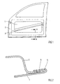
- FIG. 1 is the inside of an unclothed door of a motor vehicle shown.
- This door which is still in the body shell stage, consists of a door outer 1 and a door inner panel 2 and a strut 3 arranged between these door panels, which is intended to reinforce the door in the event of a side impact.
- Fig. 2 is a cut through the door of the Fig. 1 shown along the line AA.
- the door outer 1 is connected to the door inner panel 2 by means of a flare, for which purpose the door outer panel 1 is bent around the edge of the inner door panel 2.
- the two door panels are additionally connected at a plurality of defined points in the region of the fold by means of an additional clinch connection 5.
- the door outer panel 1 is driven by means of a punch (not shown) in an already provided opening of the door inner panel 2 and thereby plastically deformed.
Abstract
Description
Die Erfindung betrifft ein Verfahren zum Herstellen einer Blechverbindung.The invention relates to a method for producing a sheet metal connection.
Karosserien von Kraftfahrzeugen bestehen aus einer Vielzahl von miteinander verbundenen Blechen, die zumeist aus Stahl oder Aluminium bestehen.Automotive bodywork consists of a large number of interconnected sheets, mostly made of steel or aluminum.
Bei Karosserieanbauteilen wie beispielsweise Türen werden die einzelnen Bleche häufig durch Bördeln miteinander verbunden. Hierbei wird ein erstes Blech um die Kante eines zweiten Blechs gebogen, wodurch ein Falz in dem ersten Blech entsteht, in dem die Kante des zweiten Blechs gehalten wird. Durch das Bördeln wird folglich eine formschlüssige Verbindung zwischen den zwei Blechen erzeugt.In bodywork components such as doors, the individual sheets are often joined together by crimping. In this case, a first sheet is bent around the edge of a second sheet, whereby a fold is formed in the first sheet in which the edge of the second sheet is held. By crimping thus a positive connection between the two sheets is produced.
Um die Festigkeit von Bördelverbindungen zu erhöhen und gleichzeitig die Korrosionsgefahr in dem Falz zu verringern, wird das Bördeln häufig gleichzeitig mit einem Verkleben der zwei Bleche in dem Kontaktbereich zwischen den Blechen im Bereich der Falz angewendet. Nach dem Aushärten des Klebstoffs wird durch diesen die Verbindung zwischen den zwei Blechen verstärkt und ein Eindringen von Feuchtigkeit in den Falz bzw. den Kontaktbereich zwischen den zwei Blechen verhindert.In order to increase the strength of flare joints and at the same time reduce the risk of corrosion in the fold, the flanging is often applied simultaneously with gluing of the two sheets in the contact area between the sheets in the region of the fold. After curing of the adhesive through this the connection between the two sheets is reinforced and prevents ingress of moisture into the fold or the contact area between the two sheets.
Anders als bei anderen mechanischen Fügeverfahren, wie beispielsweise bei Verschraubungen oder Vernietungen, verhindert eine Bördelnaht nicht vollständig ein Verschieben der miteinander verbundenen Bleche zueinander. Ein solches teilweises Verschieben der zwei Bleche zueinander wird erst nach einem Aushärten der Klebeverbindung unterbunden. Erfolgt jedoch während des Aushärtens der Klebeverbindung ein Verschieben zwischen den Blechen, so kann dies dazu führen, dass die Klebeverbindung zumindest teilweise zerstört wird, wodurch die Endfestigkeit der Verbindung herabgesetzt und die Korrosionsgefahr erhöht wird.Unlike other mechanical joining methods, such as screwing or riveting, a flanged seam does not completely prevent it a shifting of the interconnected sheets to each other. Such a partial displacement of the two sheets to each other is prevented only after curing of the adhesive bond. However, if during the curing of the adhesive joint, a displacement between the sheets, this may result in that the adhesive bond is at least partially destroyed, whereby the final strength of the compound is reduced and the risk of corrosion is increased.
Ausgehend von diesem Stand der Technik liegt der Erfindung die Aufgabe zugrunde, ein verbessertes Verfahren zur Herstellung einer Blechverbindung anzugeben.Based on this prior art, the present invention seeks to provide an improved method for producing a sheet metal connection.
Diese Aufgabe wird durch den Gegenstand des unabhängigen Patentanspruchs gelöst. Eine vorteilhafte Ausführungsform der vorliegenden Erfindung ist Gegenstand des abhängigen Patentanspruchs.This object is solved by the subject matter of the independent claim. An advantageous embodiment of the present invention is the subject of the dependent claim.
Erfindungsgemäß ist ein Verfahren zum Herstellen einer Blechverbindung vorgesehen, bei dem zur Erzeugung einer Falz ein erstes Blech um die Kante eines zweiten Blechs gebogen wird und zusätzlich im Bereich der Falz in den Kontaktbereich zwischen den Blechen ein Klebstoff eingebracht wird, wobei die zwei Bleche zusätzlich im Bereich der Falz geclincht werden.According to the invention, a method is provided for producing a sheet-metal connection, in which a first sheet is bent around the edge of a second sheet to produce a fold and, in addition, an adhesive is introduced into the contact area between the sheets in the region of the fold, wherein the two sheets additionally Area of the fold be clinched.
Beim Clinchen, das auch als Durchsetzfügen bekannt ist, handelt es sich um ein Verfahren zum Verbinden von Blechen ohne Verwendung eines Zusatzwerkstoffs. Beim Clinchen wird in einem Umformverfahren ein Blech einer Verbindung aus mindestens zwei Blechen mittels eines Stempels lokal in das zumindest zweite Blech getrieben, wodurch dieses ebenfalls umgeformt und eine hinterschnittige Verbindung zwischen den zwei Blechen erzeugt wird. Die Art der Umformung der zwei Bleche wird insbesondere durch die Form der Kavität in der darunterliegenden Matrize beeinflusst.Clinching, also known as clinching, is a method of joining sheets without using a filler material. When clinching a sheet of a compound of at least two sheets is driven by means of a stamp locally in the at least second sheet in a forming process, whereby this also formed and an undercut connection between the two sheets is produced. The type of deformation of the two sheets is influenced in particular by the shape of the cavity in the underlying die.
Durch das erfindungsgemäß vorgesehene zusätzliche Clinchen der verklebten Bördelverbindung zwischen den zwei Blechen kann wirkungsvoll ein ungewolltes Verschieben der zwei Bleche zueinander während des Aushärtens der Klebeverbindung verhindert werden. Es ist daher möglich, die miteinander verbundenen Bleche bereits weiterzuverarbeiten, auch wenn die Klebeverbindung noch nicht ausreichend ausgehärtet ist. Gegebenenfalls kann durch die zusätzliche Clinchverbindung auf das Einbringen der zwei Bleche in einen Trocken- bzw. Gelierofen verzichtet werden, der häufig im Stand der Technik für ein schnelles Aushärten der Klebeverbindung vorgesehen wird.By inventively provided additional clinching the glued flare between the two sheets can be effectively prevented unintentional displacement of the two sheets to each other during the curing of the adhesive bond. It is therefore possible to process the interconnected sheets already, even if the adhesive bond is not sufficiently cured. Optionally, can be dispensed through the additional clinching on the introduction of the two sheets in a drying or gelling oven, which is often provided in the prior art for rapid curing of the adhesive bond.
In einer bevorzugten Ausführungsform der vorliegenden Erfindung kann in das zweite Blech zunächst eine Öffnung eingebracht werden, in der das erste Blech verclincht wird. Bei dieser Ausführungsform muss während des Clinchens lediglich das erste Blech plastisch deformiert werden. Auf diese Weise können die Clinchkräfte reduziert und infolge dessen die Kosten für die Clinchvorrichtung gering gehalten werden.In a preferred embodiment of the present invention, an opening can first be introduced into the second sheet in which the first sheet is clinched. In this embodiment, only the first sheet has to be plastically deformed during clinching. In this way, the clinching forces can be reduced and as a result the costs for the clinch device can be kept low.
Die Erfindung wird nachfolgend anhand eines in den Zeichnungen dargestellten Ausführungsbeispiels näher erläutert.The invention will be explained in more detail with reference to an embodiment shown in the drawings.
In den Zeichnungen zeigt in vereinfachter Darstellung die
- Fig. 1:
- die Innenseite einer unverkleideten Tür eines Kraftfahrzeugs; und
- Fig. 2:
- einen Schnitt durch die Tür der
Fig. 1 entlang der Linie A-A.
- Fig. 1:
- the inside of an uncovered door of a motor vehicle; and
- Fig. 2:
- a cut through the door of the
Fig. 1 along the line AA.
In der
In der
Claims (2)
Applications Claiming Priority (1)
| Application Number | Priority Date | Filing Date | Title |
|---|---|---|---|
| DE200810028450 DE102008028450A1 (en) | 2008-06-14 | 2008-06-14 | Method for producing a sheet metal connection |
Publications (2)
| Publication Number | Publication Date |
|---|---|
| EP2133162A1 true EP2133162A1 (en) | 2009-12-16 |
| EP2133162B1 EP2133162B1 (en) | 2013-09-18 |
Family
ID=41128606
Family Applications (1)
| Application Number | Title | Priority Date | Filing Date |
|---|---|---|---|
| EP20090006605 Not-in-force EP2133162B1 (en) | 2008-06-14 | 2009-05-15 | Method for manufacturing a sheet metal connection |
Country Status (2)
| Country | Link |
|---|---|
| EP (1) | EP2133162B1 (en) |
| DE (1) | DE102008028450A1 (en) |
Cited By (1)
| Publication number | Priority date | Publication date | Assignee | Title |
|---|---|---|---|---|
| EP2727664A1 (en) * | 2012-11-05 | 2014-05-07 | 3M Innovative Properties Company | Method for making a hemmed structure of metal panels |
Families Citing this family (2)
| Publication number | Priority date | Publication date | Assignee | Title |
|---|---|---|---|---|
| DE202010015651U1 (en) * | 2010-11-23 | 2012-02-28 | Rehau Ag + Co. | Connecting arrangement for a motor vehicle |
| DE102019211860A1 (en) * | 2019-08-07 | 2021-02-11 | Audi Ag | Tool arrangement for the manufacturing process of fixing points |
Citations (5)
| Publication number | Priority date | Publication date | Assignee | Title |
|---|---|---|---|---|
| JPS61148427U (en) * | 1985-03-06 | 1986-09-12 | ||
| JPS62127325A (en) | 1985-11-26 | 1987-06-09 | Hitachi Chem Co Ltd | Production of flame-retarding phenolic resin laminate |
| JPS62127325U (en) * | 1986-01-31 | 1987-08-12 | ||
| US6368008B1 (en) * | 2000-05-24 | 2002-04-09 | Daimlerchrysler Corporation | Sealed edge joint between two metal panels |
| US20050102817A1 (en) | 2003-11-19 | 2005-05-19 | Ford Global Technologies, Llc | Hem construction for vehicular closure structure |
Family Cites Families (3)
| Publication number | Priority date | Publication date | Assignee | Title |
|---|---|---|---|---|
| DE19746165A1 (en) * | 1997-10-18 | 1999-04-22 | Volkswagen Ag | Composite formed of light metal component and additional part located on it |
| DE19800035A1 (en) * | 1998-01-02 | 1999-07-08 | Volkswagen Ag | Joining of magnesium and plastic components especially of an automobile body |
| DE102005057259B4 (en) * | 2005-12-01 | 2011-04-07 | Audi Ag | Method for producing a hybrid component |
-
2008
- 2008-06-14 DE DE200810028450 patent/DE102008028450A1/en not_active Withdrawn
-
2009
- 2009-05-15 EP EP20090006605 patent/EP2133162B1/en not_active Not-in-force
Patent Citations (5)
| Publication number | Priority date | Publication date | Assignee | Title |
|---|---|---|---|---|
| JPS61148427U (en) * | 1985-03-06 | 1986-09-12 | ||
| JPS62127325A (en) | 1985-11-26 | 1987-06-09 | Hitachi Chem Co Ltd | Production of flame-retarding phenolic resin laminate |
| JPS62127325U (en) * | 1986-01-31 | 1987-08-12 | ||
| US6368008B1 (en) * | 2000-05-24 | 2002-04-09 | Daimlerchrysler Corporation | Sealed edge joint between two metal panels |
| US20050102817A1 (en) | 2003-11-19 | 2005-05-19 | Ford Global Technologies, Llc | Hem construction for vehicular closure structure |
Cited By (3)
| Publication number | Priority date | Publication date | Assignee | Title |
|---|---|---|---|---|
| EP2727664A1 (en) * | 2012-11-05 | 2014-05-07 | 3M Innovative Properties Company | Method for making a hemmed structure of metal panels |
| WO2014070707A1 (en) * | 2012-11-05 | 2014-05-08 | 3M Innovative Properties Company | Method for making a hemmed structure of metal panels |
| CN104768673A (en) * | 2012-11-05 | 2015-07-08 | 3M创新有限公司 | Method for making a hemmed structure of metal panels |
Also Published As
| Publication number | Publication date |
|---|---|
| EP2133162B1 (en) | 2013-09-18 |
| DE102008028450A1 (en) | 2009-12-17 |
Similar Documents
| Publication | Publication Date | Title |
|---|---|---|
| DE102009005606B9 (en) | Bumper for a motor vehicle | |
| EP2217393B1 (en) | Production method of highly dimensionally accurate half shells | |
| DE102006049146B4 (en) | Method for producing an assembly consisting of at least two interconnected sheet-metal parts | |
| DE102006049145A1 (en) | Procedure for connection of sheet metal form parts for the production of assembly of vehicle body, by heating a section of a sheet metal part connected with other part, and producing a power and/or form lock connection with other part | |
| DE102005057259B4 (en) | Method for producing a hybrid component | |
| EP2133162B1 (en) | Method for manufacturing a sheet metal connection | |
| EP2571635A1 (en) | Method for producing a hollow profiled section | |
| WO1998018670A1 (en) | Cpkd car body | |
| DE102004033184A1 (en) | Method for producing an attachment | |
| DE10101927B4 (en) | Structural component of a motor vehicle body and method for producing such a structural component | |
| DE102009014206A1 (en) | Supporting structural component i.e. cockpit transverse beam, for passenger car, has connection area for fixation at motor vehicle-body-sided component, and holes provided in connection area in casing wall of component | |
| DE102008028686A1 (en) | Composite component i.e. steel-aluminum composite component, for use in e.g. A-column of motor vehicle, has plastic foil arranged in partial area of sealing flange between steel shells and aluminum component | |
| DE102008054159B4 (en) | Method for producing a terminal strip | |
| DE102016200357A1 (en) | Method for joining at least two components by means of a hardened joining element | |
| DE102012021756B4 (en) | Process for producing a riveted joint | |
| DE10231864A1 (en) | Body sheet metal component and method for its production | |
| DE10323740B4 (en) | Assembly, with a punch rivet and at least two components to be joined | |
| DE102013013001B3 (en) | Method for producing a folding and gluing connection between sheet metal components and component composite | |
| DE102014001230B4 (en) | Elongated body support of a vehicle body | |
| DE102011089237B4 (en) | Joint connection between at least two components, component arrangement and method for providing a component arrangement | |
| EP3095678B1 (en) | Method for producing a body structure for a double-track vehicle | |
| EP2095890B1 (en) | Method for shaping a hollow profile component with high internal pressure | |
| EP1664473B1 (en) | Process for producing a hollow door element for a door leaf composed of a hollow element and a cover element | |
| DE102015220971A1 (en) | Body and / or structural component and method and apparatus for forming a joint flange said body and / or structural component | |
| WO2021094147A1 (en) | Method for the production of an at least partly closed sheet metal profile |
Legal Events
| Date | Code | Title | Description |
|---|---|---|---|
| PUAI | Public reference made under article 153(3) epc to a published international application that has entered the european phase |
Free format text: ORIGINAL CODE: 0009012 |
|
| AK | Designated contracting states |
Kind code of ref document: A1 Designated state(s): AT BE BG CH CY CZ DE DK EE ES FI FR GB GR HR HU IE IS IT LI LT LU LV MC MK MT NL NO PL PT RO SE SI SK TR |
|
| 17P | Request for examination filed |
Effective date: 20100120 |
|
| GRAP | Despatch of communication of intention to grant a patent |
Free format text: ORIGINAL CODE: EPIDOSNIGR1 |
|
| INTG | Intention to grant announced |
Effective date: 20130528 |
|
| GRAS | Grant fee paid |
Free format text: ORIGINAL CODE: EPIDOSNIGR3 |
|
| GRAA | (expected) grant |
Free format text: ORIGINAL CODE: 0009210 |
|
| AK | Designated contracting states |
Kind code of ref document: B1 Designated state(s): AT BE BG CH CY CZ DE DK EE ES FI FR GB GR HR HU IE IS IT LI LT LU LV MC MK MT NL NO PL PT RO SE SI SK TR |
|
| REG | Reference to a national code |
Ref country code: GB Ref legal event code: FG4D Free format text: NOT ENGLISH |
|
| REG | Reference to a national code |
Ref country code: CH Ref legal event code: EP |
|
| REG | Reference to a national code |
Ref country code: IE Ref legal event code: FG4D Free format text: LANGUAGE OF EP DOCUMENT: GERMAN |
|
| REG | Reference to a national code |
Ref country code: AT Ref legal event code: REF Ref document number: 632461 Country of ref document: AT Kind code of ref document: T Effective date: 20131015 |
|
| REG | Reference to a national code |
Ref country code: DE Ref legal event code: R096 Ref document number: 502009008020 Country of ref document: DE Effective date: 20131114 |
|
| PG25 | Lapsed in a contracting state [announced via postgrant information from national office to epo] |
Ref country code: SE Free format text: LAPSE BECAUSE OF FAILURE TO SUBMIT A TRANSLATION OF THE DESCRIPTION OR TO PAY THE FEE WITHIN THE PRESCRIBED TIME-LIMIT Effective date: 20130918 Ref country code: CY Free format text: LAPSE BECAUSE OF FAILURE TO SUBMIT A TRANSLATION OF THE DESCRIPTION OR TO PAY THE FEE WITHIN THE PRESCRIBED TIME-LIMIT Effective date: 20130814 Ref country code: LT Free format text: LAPSE BECAUSE OF FAILURE TO SUBMIT A TRANSLATION OF THE DESCRIPTION OR TO PAY THE FEE WITHIN THE PRESCRIBED TIME-LIMIT Effective date: 20130918 Ref country code: HR Free format text: LAPSE BECAUSE OF FAILURE TO SUBMIT A TRANSLATION OF THE DESCRIPTION OR TO PAY THE FEE WITHIN THE PRESCRIBED TIME-LIMIT Effective date: 20130918 Ref country code: NO Free format text: LAPSE BECAUSE OF FAILURE TO SUBMIT A TRANSLATION OF THE DESCRIPTION OR TO PAY THE FEE WITHIN THE PRESCRIBED TIME-LIMIT Effective date: 20131218 |
|
| REG | Reference to a national code |
Ref country code: NL Ref legal event code: VDEP Effective date: 20130918 |
|
| REG | Reference to a national code |
Ref country code: LT Ref legal event code: MG4D |
|
| PG25 | Lapsed in a contracting state [announced via postgrant information from national office to epo] |
Ref country code: SI Free format text: LAPSE BECAUSE OF FAILURE TO SUBMIT A TRANSLATION OF THE DESCRIPTION OR TO PAY THE FEE WITHIN THE PRESCRIBED TIME-LIMIT Effective date: 20130918 Ref country code: GR Free format text: LAPSE BECAUSE OF FAILURE TO SUBMIT A TRANSLATION OF THE DESCRIPTION OR TO PAY THE FEE WITHIN THE PRESCRIBED TIME-LIMIT Effective date: 20131219 Ref country code: LV Free format text: LAPSE BECAUSE OF FAILURE TO SUBMIT A TRANSLATION OF THE DESCRIPTION OR TO PAY THE FEE WITHIN THE PRESCRIBED TIME-LIMIT Effective date: 20130918 Ref country code: FI Free format text: LAPSE BECAUSE OF FAILURE TO SUBMIT A TRANSLATION OF THE DESCRIPTION OR TO PAY THE FEE WITHIN THE PRESCRIBED TIME-LIMIT Effective date: 20130918 |
|
| PG25 | Lapsed in a contracting state [announced via postgrant information from national office to epo] |
Ref country code: CY Free format text: LAPSE BECAUSE OF FAILURE TO SUBMIT A TRANSLATION OF THE DESCRIPTION OR TO PAY THE FEE WITHIN THE PRESCRIBED TIME-LIMIT Effective date: 20130918 |
|
| PG25 | Lapsed in a contracting state [announced via postgrant information from national office to epo] |
Ref country code: NL Free format text: LAPSE BECAUSE OF FAILURE TO SUBMIT A TRANSLATION OF THE DESCRIPTION OR TO PAY THE FEE WITHIN THE PRESCRIBED TIME-LIMIT Effective date: 20130918 Ref country code: RO Free format text: LAPSE BECAUSE OF FAILURE TO SUBMIT A TRANSLATION OF THE DESCRIPTION OR TO PAY THE FEE WITHIN THE PRESCRIBED TIME-LIMIT Effective date: 20130918 Ref country code: IS Free format text: LAPSE BECAUSE OF FAILURE TO SUBMIT A TRANSLATION OF THE DESCRIPTION OR TO PAY THE FEE WITHIN THE PRESCRIBED TIME-LIMIT Effective date: 20140118 Ref country code: EE Free format text: LAPSE BECAUSE OF FAILURE TO SUBMIT A TRANSLATION OF THE DESCRIPTION OR TO PAY THE FEE WITHIN THE PRESCRIBED TIME-LIMIT Effective date: 20130918 Ref country code: SK Free format text: LAPSE BECAUSE OF FAILURE TO SUBMIT A TRANSLATION OF THE DESCRIPTION OR TO PAY THE FEE WITHIN THE PRESCRIBED TIME-LIMIT Effective date: 20130918 Ref country code: CZ Free format text: LAPSE BECAUSE OF FAILURE TO SUBMIT A TRANSLATION OF THE DESCRIPTION OR TO PAY THE FEE WITHIN THE PRESCRIBED TIME-LIMIT Effective date: 20130918 |
|
| PG25 | Lapsed in a contracting state [announced via postgrant information from national office to epo] |
Ref country code: ES Free format text: LAPSE BECAUSE OF FAILURE TO SUBMIT A TRANSLATION OF THE DESCRIPTION OR TO PAY THE FEE WITHIN THE PRESCRIBED TIME-LIMIT Effective date: 20130918 Ref country code: PL Free format text: LAPSE BECAUSE OF FAILURE TO SUBMIT A TRANSLATION OF THE DESCRIPTION OR TO PAY THE FEE WITHIN THE PRESCRIBED TIME-LIMIT Effective date: 20130918 |
|
| REG | Reference to a national code |
Ref country code: DE Ref legal event code: R097 Ref document number: 502009008020 Country of ref document: DE |
|
| PG25 | Lapsed in a contracting state [announced via postgrant information from national office to epo] |
Ref country code: PT Free format text: LAPSE BECAUSE OF FAILURE TO SUBMIT A TRANSLATION OF THE DESCRIPTION OR TO PAY THE FEE WITHIN THE PRESCRIBED TIME-LIMIT Effective date: 20140120 |
|
| RAP2 | Party data changed (patent owner data changed or rights of a patent transferred) |
Owner name: BAYERISCHE MOTOREN WERKE AKTIENGESELLSCHAFT |
|
| PLBE | No opposition filed within time limit |
Free format text: ORIGINAL CODE: 0009261 |
|
| STAA | Information on the status of an ep patent application or granted ep patent |
Free format text: STATUS: NO OPPOSITION FILED WITHIN TIME LIMIT |
|
| 26N | No opposition filed |
Effective date: 20140619 |
|
| PG25 | Lapsed in a contracting state [announced via postgrant information from national office to epo] |
Ref country code: DK Free format text: LAPSE BECAUSE OF FAILURE TO SUBMIT A TRANSLATION OF THE DESCRIPTION OR TO PAY THE FEE WITHIN THE PRESCRIBED TIME-LIMIT Effective date: 20130918 |
|
| REG | Reference to a national code |
Ref country code: DE Ref legal event code: R097 Ref document number: 502009008020 Country of ref document: DE Effective date: 20140619 |
|
| PG25 | Lapsed in a contracting state [announced via postgrant information from national office to epo] |
Ref country code: LU Free format text: LAPSE BECAUSE OF FAILURE TO SUBMIT A TRANSLATION OF THE DESCRIPTION OR TO PAY THE FEE WITHIN THE PRESCRIBED TIME-LIMIT Effective date: 20140515 |
|
| REG | Reference to a national code |
Ref country code: CH Ref legal event code: PL |
|
| PG25 | Lapsed in a contracting state [announced via postgrant information from national office to epo] |
Ref country code: CH Free format text: LAPSE BECAUSE OF NON-PAYMENT OF DUE FEES Effective date: 20140531 Ref country code: MC Free format text: LAPSE BECAUSE OF FAILURE TO SUBMIT A TRANSLATION OF THE DESCRIPTION OR TO PAY THE FEE WITHIN THE PRESCRIBED TIME-LIMIT Effective date: 20130918 Ref country code: LI Free format text: LAPSE BECAUSE OF NON-PAYMENT OF DUE FEES Effective date: 20140531 |
|
| REG | Reference to a national code |
Ref country code: IE Ref legal event code: MM4A |
|
| PG25 | Lapsed in a contracting state [announced via postgrant information from national office to epo] |
Ref country code: IE Free format text: LAPSE BECAUSE OF NON-PAYMENT OF DUE FEES Effective date: 20140515 |
|
| REG | Reference to a national code |
Ref country code: AT Ref legal event code: MM01 Ref document number: 632461 Country of ref document: AT Kind code of ref document: T Effective date: 20140515 |
|
| PG25 | Lapsed in a contracting state [announced via postgrant information from national office to epo] |
Ref country code: AT Free format text: LAPSE BECAUSE OF NON-PAYMENT OF DUE FEES Effective date: 20140515 |
|
| PG25 | Lapsed in a contracting state [announced via postgrant information from national office to epo] |
Ref country code: MT Free format text: LAPSE BECAUSE OF FAILURE TO SUBMIT A TRANSLATION OF THE DESCRIPTION OR TO PAY THE FEE WITHIN THE PRESCRIBED TIME-LIMIT Effective date: 20130918 |
|
| REG | Reference to a national code |
Ref country code: FR Ref legal event code: PLFP Year of fee payment: 8 |
|
| PG25 | Lapsed in a contracting state [announced via postgrant information from national office to epo] |
Ref country code: BG Free format text: LAPSE BECAUSE OF FAILURE TO SUBMIT A TRANSLATION OF THE DESCRIPTION OR TO PAY THE FEE WITHIN THE PRESCRIBED TIME-LIMIT Effective date: 20130918 |
|
| PG25 | Lapsed in a contracting state [announced via postgrant information from national office to epo] |
Ref country code: TR Free format text: LAPSE BECAUSE OF FAILURE TO SUBMIT A TRANSLATION OF THE DESCRIPTION OR TO PAY THE FEE WITHIN THE PRESCRIBED TIME-LIMIT Effective date: 20130918 Ref country code: BE Free format text: LAPSE BECAUSE OF FAILURE TO SUBMIT A TRANSLATION OF THE DESCRIPTION OR TO PAY THE FEE WITHIN THE PRESCRIBED TIME-LIMIT Effective date: 20140531 Ref country code: HU Free format text: LAPSE BECAUSE OF FAILURE TO SUBMIT A TRANSLATION OF THE DESCRIPTION OR TO PAY THE FEE WITHIN THE PRESCRIBED TIME-LIMIT; INVALID AB INITIO Effective date: 20090515 |
|
| PGFP | Annual fee paid to national office [announced via postgrant information from national office to epo] |
Ref country code: DE Payment date: 20160521 Year of fee payment: 8 |
|
| REG | Reference to a national code |
Ref country code: FR Ref legal event code: PLFP Year of fee payment: 9 |
|
| PGFP | Annual fee paid to national office [announced via postgrant information from national office to epo] |
Ref country code: GB Payment date: 20170524 Year of fee payment: 9 Ref country code: FR Payment date: 20170522 Year of fee payment: 9 |
|
| PGFP | Annual fee paid to national office [announced via postgrant information from national office to epo] |
Ref country code: IT Payment date: 20170524 Year of fee payment: 9 |
|
| REG | Reference to a national code |
Ref country code: DE Ref legal event code: R119 Ref document number: 502009008020 Country of ref document: DE |
|
| PG25 | Lapsed in a contracting state [announced via postgrant information from national office to epo] |
Ref country code: DE Free format text: LAPSE BECAUSE OF NON-PAYMENT OF DUE FEES Effective date: 20171201 |
|
| PG25 | Lapsed in a contracting state [announced via postgrant information from national office to epo] |
Ref country code: MK Free format text: LAPSE BECAUSE OF FAILURE TO SUBMIT A TRANSLATION OF THE DESCRIPTION OR TO PAY THE FEE WITHIN THE PRESCRIBED TIME-LIMIT Effective date: 20130918 |
|
| GBPC | Gb: european patent ceased through non-payment of renewal fee |
Effective date: 20180515 |
|
| PG25 | Lapsed in a contracting state [announced via postgrant information from national office to epo] |
Ref country code: FR Free format text: LAPSE BECAUSE OF NON-PAYMENT OF DUE FEES Effective date: 20180531 Ref country code: IT Free format text: LAPSE BECAUSE OF NON-PAYMENT OF DUE FEES Effective date: 20180515 Ref country code: GB Free format text: LAPSE BECAUSE OF NON-PAYMENT OF DUE FEES Effective date: 20180515 |