EP2133032A1 - A bladed/bladeless obturator for use in a surgical trocar assembly - Google Patents
A bladed/bladeless obturator for use in a surgical trocar assembly Download PDFInfo
- Publication number
- EP2133032A1 EP2133032A1 EP09251393A EP09251393A EP2133032A1 EP 2133032 A1 EP2133032 A1 EP 2133032A1 EP 09251393 A EP09251393 A EP 09251393A EP 09251393 A EP09251393 A EP 09251393A EP 2133032 A1 EP2133032 A1 EP 2133032A1
- Authority
- EP
- European Patent Office
- Prior art keywords
- obturator
- assembly
- housing
- cutting blade
- recited
- Prior art date
- Legal status (The legal status is an assumption and is not a legal conclusion. Google has not performed a legal analysis and makes no representation as to the accuracy of the status listed.)
- Withdrawn
Links
- 238000005520 cutting process Methods 0.000 claims abstract description 103
- 238000004891 communication Methods 0.000 claims abstract description 7
- 239000012811 non-conductive material Substances 0.000 claims description 6
- 239000004020 conductor Substances 0.000 claims description 5
- 210000000056 organ Anatomy 0.000 description 6
- 239000012530 fluid Substances 0.000 description 4
- 230000006378 damage Effects 0.000 description 3
- 230000037361 pathway Effects 0.000 description 3
- 230000009471 action Effects 0.000 description 2
- 238000003780 insertion Methods 0.000 description 2
- 230000037431 insertion Effects 0.000 description 2
- 230000033001 locomotion Effects 0.000 description 2
- 230000007246 mechanism Effects 0.000 description 2
- 238000000034 method Methods 0.000 description 2
- 238000012986 modification Methods 0.000 description 2
- 230000004048 modification Effects 0.000 description 2
- 230000035515 penetration Effects 0.000 description 2
- 208000027418 Wounds and injury Diseases 0.000 description 1
- 210000003815 abdominal wall Anatomy 0.000 description 1
- 238000004026 adhesive bonding Methods 0.000 description 1
- 230000000712 assembly Effects 0.000 description 1
- 238000000429 assembly Methods 0.000 description 1
- 230000008901 benefit Effects 0.000 description 1
- 230000005540 biological transmission Effects 0.000 description 1
- 238000002788 crimping Methods 0.000 description 1
- 230000000994 depressogenic effect Effects 0.000 description 1
- 239000007789 gas Substances 0.000 description 1
- 208000014674 injury Diseases 0.000 description 1
- 238000002324 minimally invasive surgery Methods 0.000 description 1
- 238000012978 minimally invasive surgical procedure Methods 0.000 description 1
- 230000000149 penetrating effect Effects 0.000 description 1
- 239000003356 suture material Substances 0.000 description 1
- 238000003466 welding Methods 0.000 description 1
Images



Classifications
-
- A—HUMAN NECESSITIES
- A61—MEDICAL OR VETERINARY SCIENCE; HYGIENE
- A61B—DIAGNOSIS; SURGERY; IDENTIFICATION
- A61B17/00—Surgical instruments, devices or methods
- A61B17/34—Trocars; Puncturing needles
- A61B17/3494—Trocars; Puncturing needles with safety means for protection against accidental cutting or pricking, e.g. limiting insertion depth, pressure sensors
- A61B17/3496—Protecting sleeves or inner probes; Retractable tips
-
- A—HUMAN NECESSITIES
- A61—MEDICAL OR VETERINARY SCIENCE; HYGIENE
- A61B—DIAGNOSIS; SURGERY; IDENTIFICATION
- A61B17/00—Surgical instruments, devices or methods
- A61B17/34—Trocars; Puncturing needles
- A61B17/3417—Details of tips or shafts, e.g. grooves, expandable, bendable; Multiple coaxial sliding cannulas, e.g. for dilating
- A61B17/3421—Cannulas
-
- A—HUMAN NECESSITIES
- A61—MEDICAL OR VETERINARY SCIENCE; HYGIENE
- A61B—DIAGNOSIS; SURGERY; IDENTIFICATION
- A61B17/00—Surgical instruments, devices or methods
- A61B17/34—Trocars; Puncturing needles
- A61B17/3474—Insufflating needles, e.g. Veress needles
-
- A—HUMAN NECESSITIES
- A61—MEDICAL OR VETERINARY SCIENCE; HYGIENE
- A61B—DIAGNOSIS; SURGERY; IDENTIFICATION
- A61B18/00—Surgical instruments, devices or methods for transferring non-mechanical forms of energy to or from the body
- A61B18/04—Surgical instruments, devices or methods for transferring non-mechanical forms of energy to or from the body by heating
- A61B18/12—Surgical instruments, devices or methods for transferring non-mechanical forms of energy to or from the body by heating by passing a current through the tissue to be heated, e.g. high-frequency current
- A61B18/14—Probes or electrodes therefor
- A61B18/1487—Trocar-like, i.e. devices producing an enlarged transcutaneous opening
-
- A—HUMAN NECESSITIES
- A61—MEDICAL OR VETERINARY SCIENCE; HYGIENE
- A61B—DIAGNOSIS; SURGERY; IDENTIFICATION
- A61B17/00—Surgical instruments, devices or methods
- A61B17/34—Trocars; Puncturing needles
- A61B17/3417—Details of tips or shafts, e.g. grooves, expandable, bendable; Multiple coaxial sliding cannulas, e.g. for dilating
- A61B2017/3454—Details of tips
- A61B2017/3456—Details of tips blunt
Definitions
- the present disclosure relates to an obturator assembly for use in a surgical trocar assembly. More particularly, the present disclosure relates to an obturator assembly having a bladeless tip and a retractable bladed cutting surface within the bladeless tip.
- Minimally invasive procedures are continually increasing in number and variation. Forming a relatively small diameter, temporary pathway to the surgical site is a key feature of most minimally invasive surgical procedures.
- the most common method of providing such a pathway is by inserting a trocar assembly through the skin.
- Common trocar assemblies generally include an obturator assembly for penetrating the skin and a cannula assembly for providing a sealed passageway for insertion of surgical instruments into a body cavity.
- the trocar assembly is inserted into a body cavity of a patient and the body cavity is insufflated to provide a working space.
- the cannula assembly Upon removal of the obturator assembly, the cannula assembly is utilized to provide the necessary pathway to the surgical site while minimizing leakage of insufflation gases.
- the obturator assembly may include a safety shield which protects against unintentional puncturing by a sharpened tip of the obturator assembly.
- a safety shield mechanism is disclosed in commonly assigned US Patent Number 6, 319, 266 to Stellon et al. , the entire disclosure of which is incorporated by reference herein.
- an obturator assembly which includes multiple safety mechanisms to prevent engagement of the sharpened tip of the obturator assembly with the underlying organs. It is further desirable to provide an obturator assembly having an obturator member and cutting blade which may be manually advanced to expose the cutting blade to tissue.
- An obturator assembly is provided and generally includes an obturator housing and a support tube extending distally from the obturator housing.
- a shield nose is affixed to a distal end of the support tube.
- the shield nose defines a truncated cavity and includes a concave center portion.
- An obturator member is movably mounted relative to the support tube.
- a cutting blade is provided having at least one cutting edge and is affixed adjacent a distal end of the obturator member. The cutting blade is movable within the truncated cavity.
- the shield nose has at least one slot, formed through the concave center portion, in communication with the truncated cavity for allowing passage of the at least one cutting edge therethrough.
- the shield nose has a blunt tip distal of the truncated cavity.
- the truncated cavity includes a planner portion for receipt of the cutting blade.
- the truncated cavity also includes a cylindrical portion for receipt of the distal end of the obturator member.
- a spring is positioned between the obturator housing and the obturator member to bias the obturator member proximally relative to the support tube.
- a plunger is affixed to a proximal end of the obturator member to manually move the obturator member relative to the support tube.
- an electrical conduit is attached to the obturator housing and is in electrical connection with the cutting blade to provide electrocautery features to the cutting blade.
- the obturator member is formed of an electrically conductive material.
- the obturator member is formed of an electrically nonconductive material and includes an electrically conductive inner core in electrical contact with the cutting blade.
- an obturator assembly generally including an obturator housing, a support tube extending distally from the obturator housing and a shield nose affixed to a distal end of the support tube, the shield nose defining a cavity.
- An obturator member is movably mounted relative to the support tube.
- a cutting blade having at least one cutting edge, is affixed to a distal end of the obturator member. The cutting blade is movable within the cavity.
- the obturator assembly further includes a safety shield movably mounted to the obturator housing.
- a spring is provided and is engageable with the safety shield to bias the safety shield distally relative to the obturator housing.
- a driver is engageable with the spring and is affixed to a proximal end of the safety shield.
- a guide is formed in the obturator housing and a tab is formed on the driver and is movable within the guide.
- the shield nose has a concave center portion and at least one slot formed through the concave center portion and in communication therewith for allowing passage of the at least one cutting edge therethrough.
- a trocar assembly generally including a cannula assembly having a cannula housing and a cannula sleeve extending distally from the cannula housing and an obturator assembly insertable through the cannula assembly.
- the obturator assembly includes an obturator housing and a support tube extending distally from the obturator housing.
- a shield nose is affixed to a distal end of the support tube and defines a cavity.
- An obturator member is movably mounted relative to the support tube.
- a cutting blade having at least one cutting edge is provided and is affixed to a distal end of the obturator member. The cutting blade is movable within the cavity.
- the disclosed trocar assembly further includes a safety shield movably mounted to the obturator housing.
- the cannula housing includes a valve positioned within an interior of the cannula housing such that the valve seals about the safety shield when the obturator assembly is inserted into the cannula assembly.
- obturator assembly An embodiment of the presently disclosed obturator assembly will now be described in detail with reference to the drawings wherein like numerals designate identical or corresponding elements in each of the several views.
- proximal refers to that part or component closer to the user or operator, i.e. surgeon or physician
- distal refers to that part or component further away from the user.
- a trocar assembly 10 including a cannula assembly 12 and an obturator assembly 14 positioned through cannula assembly 12.
- Cannula assembly 12 provides an access port for various surgical instruments into the body as well as a conduit for a source of insuffulation fluid to insufflate the body to create a working cavity.
- cannula assembly 12 includes a cannula housing 16 and elongate cannula sleeve 18 extending distally from cannula housing 16.
- Cannula housing 16 and cannula sleeve 18 define a throughbore 20 which extends from a proximal end 22 of cannula housing 16 to a distal end 24 of cannula sleeve 18.
- a check valve 26 is provided on cannula housing 16 to receive a source of insuffulation fluid for passage into the body of a patient.
- Cannula housing 16 is additionally provided with a pair of suture wings 28 and 30 to facilitate securing cannula assembly 12 to the body of a patient.
- suture wings 28 and 30 include respective slots 32a-c and 34a-c for receipt of lengths of suture material to secure cannula assembly 12 to the patient's body.
- Obturator assembly 14 generally includes an obturator housing 38 and an elongate safety shield 40 extending distally from, and movably mounted within, obturator housing 38.
- Safety shield 40 is provided to automatically cover a cutting device associated with obturator assembly 14 (as described in more detail hereinbelow) once the cutting device has penetrated the body of a patient to prevent puncturing of underlying organs the wall of the patient punctured.
- obturator housing 38 includes an upper housing 42 and a lower housing 44.
- a plurality of tabs 46a-c are provided on lower housing 44 and engage a corresponding plurality of slots 48a-c to hold upper housing and 42 and lower housing 44 together.
- safety shield 40 is movably mounted within obturator housing 38.
- a driver 50 is movably mounted within upper housing 42 and lower housing 44 and is affixed to a proximal end 52 of safety shield 40.
- a distal end 54 of driver 50 is affixed to proximal end 52 of safety shield 40 (see FIG. 8 ).
- Safety shield 40 passes through a hole 56 formed in lower housing 44.
- a spring 58 is provided within obturator housing 38 to bias safety shield 40 distally relative to obturator housing 38.
- Spring 58 engages a proximal end 60 of driver 50.
- a proximal end 62 of spring 58 abuts a support 64 formed in upper housing 42.
- a guide 66 is provided on lower housing 44 and includes a longitudinally extending slot 68.
- Driver 50 is provided with a tab 70 which rides within slot 68.
- guide 66 controls the longitudinal motion of driver 50 within obturator housing 38.
- obturator assembly 14 In order to puncture tissue, such as, for example, the wall of a body cavity, obturator assembly 14 is provided with an elongate obturator member 72 having a cutting blade 74 positioned on a distal end 76 of obturator member 72. A pair of longitudinally extending arms 78a and 78b are provided on distal end 76 of obturator member 72 to secure cutting blade 74 thereon. A shield nose 80 and a support tube 82 are associated with obturator assembly 14 and are provided to shield blade 74 when not in use.
- a proximal end 84 of shield nose 80 is affixed to a distal end 86 of support tube 82 by any of various known means, such as, for example, crimping, welding, gluing, etc.
- a proximal end 88 of support tube 82 is fixedly secured to support 64 in upper housing 42.
- Shield nose 80 is provided with a truncated cavity 90 for receipt of cutting blade 74. Shield nose 80 is further provided with a blunt tip 92 to prevent injury to organs underlying the wall of a body cavity during insertion therethrough.
- a plunger 94 is provided through upper housing 42.
- Plunger 94 includes a handle 96 and a tube 98 extending distally from handle 96. Tube 98 extends through a plunger hole 100 formed within upper housing 42.
- a proximal end 102 is affixed within a bore 104 formed within tube 98.
- a spring 106 is provided about proximal end 102 of obturator member 72 to bias obturator member 72 within support to 82.
- cutting blade 74 is biased proximally within truncated cavity 90 of shield nose 80.
- support tube 82 and shield nose 80 are illustrated as being fixed relative to obturator housing 38 and obturator member 72 and cutting blade 64 are disclosed as being movable relative to obturator housing 38, it is within the contemplated scope of the present disclosure that obturator member 72 and cutting blade 64 may be fixed relative to obturator housing 38 and shield nose 80 and support tube 82 movably mounted relative to obturator housing 38.
- tissue pressure against shield nose 80 will allow shield nose 80 and support tube 82 to move proximally, against the bias of spring 106, relative to cutting blade 64 to expose cutting blade 64 to tissue.
- shield nose 80 Upon the release of pressure against shield nose 80, shield nose 80 than advances distally against the bias of spring 106 to go cover and shield cutting blade 64 from exposure to underlying tissues.
- obturator assembly 14 In certain situations, it is desirable to provide electrocautery features to obturator assembly 14 and, specifically to cutting blade 74.
- an electrical conduit 108 is provided on upper housing 42 and is in electrical connection with obturator member 72 as described in more detail hereinbelow.
- obturator member 72 may be formed of a conductive material or, may be formed of a non-conductive material having a conductive inner core for transmission of electrical power to cutting blade 74.
- shield nose 80 includes a conical, concave center section 110 extending proximally from blunt tip 92.
- Shield nose 80 additionally includes a generally cylindrical proximal end 112.
- shield nose 80 is provided with a truncated cavity 90 for receipt of cutting blade 64.
- truncated cavity 90 generally includes a cylindrical center portion 114 which intersects a planner portion 116. Cylindrical portion 114 is configured to receive distal end 76 and arms 78a and 78b of obturator member 72 while planner portion 116 receives and supports cutting blade 64.
- cutting blade 64 is generally planner and includes a pair of sharp convex cutting side edges 124 and 126. Cutting blade 64 terminates in a blunt atraumatic truncated tip 128.
- shield nose 80 is illustrated within a bore 130 of safety shield 40. Specifically, in the assembled condition, shield nose 80 is initially positioned within bore 130 at a distal end 132 of safety shield 40.
- cutting side edges 124 and 126 are proximal within planner portion 116 of truncated cavity 90.
- cutting side edges 124 and 126 are shielded from contact with surrounding body tissue when cutting blade 64 is in the proximal most position within truncated cavity 90 of shield nose 80.
- cutting side edges 124 and 126 of cutting blade 64 project through slots 118 and 120 formed through side surface 122 of conical concave center section 110 of shield nose 80 and are in a position to cut tissue.
- cannula assembly 12 includes a valve 26 for receipt of a source of insuffulation fluid.
- cannula assembly 12 is provided with a duckbill valve 134 located within an interior 136 of cannula housing 16.
- Duckbill valve 134 is in a normally closed position and is provided to seal about safety shield 40 when obturator assembly 14 is inserted through cannula assembly 12.
- Cannula assembly 12 includes electrical conduit 108.
- electrical conduit 108 generally includes a connector 138 affixed to upper housing 38 and a cable 140 extending from connector 138 to obturator member 72.
- a wire 142 extends from cable 140 and passes through support 64 in upper housing 42.
- a wiper 144 is affixed to wire 142 and is in electrical contact with obturator member 72.
- safety shield 40 is affixed to driver 50.
- driver 50 is provided with one or more tabs 146 which are configured to reside within slots 148 formed in proximal end 52 of safety shield 40. (See also FIG. 3 ).
- obturator assembly 14 in the assembled condition of trocar assembly 10, obturator assembly 14 is inserted through cannula assembly 12. Specifically, safety shield 40 and obturator member 72 of obturator assembly 14 are inserted through cannula housing 16 and cannula sleeve 18. Duckbill valve 134 provided within interior 136 of cannula housing 16 seals about safety shield 40. Plunger 94 is in the proximal most positioned against the bias of spring 106 to position cutting blade 64 in the proximal most position within shield nose 80. As shown, shield nose 80 and cutting blade 64 are in a proximal position within distal end 132 of safety shield 40. (See also FIGS. 4 and 4a ).
- trocar assembly 10 is positioned adjacent a tissue T such as an abdominal wall such that a distal end 150 of safety shield 40 abuts a body wall BW of tissue T.
- a cavity C exists beneath body wall BW and contains the desired organs to be operated upon (not shown).
- plunger 94 is depressed against the bias of spring 106 to drive obturator member 72 distally relative to support tube 82.
- Cutting blade 64 it is advance to the proximal most positioned within shield nose 80 to expose convex cutting edges 124 at 126 of cutting blade 64 through shield nose 80. (See also FIGS. 5 and 5a ).
- trocar assembly 10 as a whole can be advanced against body wall BW of tissue T.
- distal end 150 of safety shield 40 engages body wall BW and is driven proximally relative to obturator housing 38 and against the bias of spring 58.
- This begins to expose cutting blade 64 to body wall BW of tissue T.
- blunt tip 92 of shield nose 80 engages body wall BW.
- blunt tip 92 is provided to prevent cutting of underlying tissues as cutting blade 64 creates an incision and passes through body wall BW.
- obturator 72 may be formed completely of a conductive material or may be formed of a non-conductive material having a conductive inner core in electrical connection with 64. In this monopolar type system cutting blade 64 is energized to facilitate cutting through body wall BW and assist in cauterizing the sides of the incision therethrough.
- safety shield 40 is driven through incision I due to the bias of spring 58 against driver 50 connected to safety shield 40. In this manner, exposed cutting blade 64 is shielded from any underlying organs to prevent damage thereto.
- pressure may be released from plunger 94 to allow cutting blade 64 to retract within shield nose 80 due to the bias of spring 106. In this manner, cutting blade 64 is safely contained within shield nose 80 to prevent damage to underlying tissues.
- the obturator member in cutting blade may be fixed relative to the obturator housing while the shield nose and support tube bias distally relative to the cutting blade.
- the cutting blade may assume other configurations than planer such as, for example, triangular, etc. with corresponding openings in the shield nose to allow exposure of the cutting blade.
- various internal components of the obturator assembly may be formed of nonconductive materials when electrocautery features are provided to the cutting blade. Therefore, the above description should not be construed as limiting, but merely as exemplifications of particular embodiments. Those skilled in the art will envision other modifications within the scope and spirit of the claims appended hereto.
Landscapes
- Health & Medical Sciences (AREA)
- Surgery (AREA)
- Life Sciences & Earth Sciences (AREA)
- Biomedical Technology (AREA)
- Nuclear Medicine, Radiotherapy & Molecular Imaging (AREA)
- Engineering & Computer Science (AREA)
- Pathology (AREA)
- Heart & Thoracic Surgery (AREA)
- Medical Informatics (AREA)
- Molecular Biology (AREA)
- Animal Behavior & Ethology (AREA)
- General Health & Medical Sciences (AREA)
- Public Health (AREA)
- Veterinary Medicine (AREA)
- Surgical Instruments (AREA)
Abstract
An obturator assembly is provided and generally includes an obturator housing and a support tube extending distally from the obturator housing. A shield nose is affixed to a distal end of the support tube. The shield nose defines a truncated cavity and having a concave center portion. An obturator member is movably mounted relative to the support tube. A cutting blade is provided having at least one cutting edge and is affixed to a distal end of the obturator member. The cutting blade is movable within the truncated cavity. The shield nose has at least one slot formed through the concave center portion and in communication with the truncated cavity for allowing passage of the at least one cutting edge therethrough.
Description
- The present application claims the benefit of and priority to
U.S. Provisional Application Serial No. 61/060,147 filed on June 10, 2008 - The present disclosure relates to an obturator assembly for use in a surgical trocar assembly. More particularly, the present disclosure relates to an obturator assembly having a bladeless tip and a retractable bladed cutting surface within the bladeless tip.
- Minimally invasive procedures are continually increasing in number and variation. Forming a relatively small diameter, temporary pathway to the surgical site is a key feature of most minimally invasive surgical procedures. The most common method of providing such a pathway is by inserting a trocar assembly through the skin. Common trocar assemblies generally include an obturator assembly for penetrating the skin and a cannula assembly for providing a sealed passageway for insertion of surgical instruments into a body cavity. In many procedures, the trocar assembly is inserted into a body cavity of a patient and the body cavity is insufflated to provide a working space. Upon removal of the obturator assembly, the cannula assembly is utilized to provide the necessary pathway to the surgical site while minimizing leakage of insufflation gases.
- The obturator assembly may include a safety shield which protects against unintentional puncturing by a sharpened tip of the obturator assembly. One example of a safety shield mechanism is disclosed in commonly assigned
US , the entire disclosure of which is incorporated by reference herein.Patent Number 6, 319, 266 to Stellon et al. - During certain particularly delicate operations care is required to prevent underlying organs from being punctured by the sharpened tip of the obturator assembly. Therefore, it is desirable to provide an obturator assembly which includes multiple safety mechanisms to prevent engagement of the sharpened tip of the obturator assembly with the underlying organs. It is further desirable to provide an obturator assembly having an obturator member and cutting blade which may be manually advanced to expose the cutting blade to tissue.
- An obturator assembly is provided and generally includes an obturator housing and a support tube extending distally from the obturator housing. A shield nose is affixed to a distal end of the support tube. The shield nose defines a truncated cavity and includes a concave center portion. An obturator member is movably mounted relative to the support tube. A cutting blade is provided having at least one cutting edge and is affixed adjacent a distal end of the obturator member. The cutting blade is movable within the truncated cavity. The shield nose has at least one slot, formed through the concave center portion, in communication with the truncated cavity for allowing passage of the at least one cutting edge therethrough. The shield nose has a blunt tip distal of the truncated cavity. The truncated cavity includes a planner portion for receipt of the cutting blade. The truncated cavity also includes a cylindrical portion for receipt of the distal end of the obturator member.
- A spring is positioned between the obturator housing and the obturator member to bias the obturator member proximally relative to the support tube. A plunger is affixed to a proximal end of the obturator member to manually move the obturator member relative to the support tube.
- In one embodiment, an electrical conduit is attached to the obturator housing and is in electrical connection with the cutting blade to provide electrocautery features to the cutting blade. In a specific embodiment, the obturator member is formed of an electrically conductive material. In an alternative specific embodiment, the obturator member is formed of an electrically nonconductive material and includes an electrically conductive inner core in electrical contact with the cutting blade.
- There is also disclosed an obturator assembly generally including an obturator housing, a support tube extending distally from the obturator housing and a shield nose affixed to a distal end of the support tube, the shield nose defining a cavity. An obturator member is movably mounted relative to the support tube. A cutting blade, having at least one cutting edge, is affixed to a distal end of the obturator member. The cutting blade is movable within the cavity. The obturator assembly further includes a safety shield movably mounted to the obturator housing.
- A spring is provided and is engageable with the safety shield to bias the safety shield distally relative to the obturator housing. A driver is engageable with the spring and is affixed to a proximal end of the safety shield.
- In one embodiment, a guide is formed in the obturator housing and a tab is formed on the driver and is movable within the guide. In a specific embodiment, the shield nose has a concave center portion and at least one slot formed through the concave center portion and in communication therewith for allowing passage of the at least one cutting edge therethrough.
- There is also disclosed a trocar assembly generally including a cannula assembly having a cannula housing and a cannula sleeve extending distally from the cannula housing and an obturator assembly insertable through the cannula assembly. The obturator assembly includes an obturator housing and a support tube extending distally from the obturator housing. A shield nose is affixed to a distal end of the support tube and defines a cavity. An obturator member is movably mounted relative to the support tube. A cutting blade having at least one cutting edge is provided and is affixed to a distal end of the obturator member. The cutting blade is movable within the cavity. The disclosed trocar assembly further includes a safety shield movably mounted to the obturator housing.
- The cannula housing includes a valve positioned within an interior of the cannula housing such that the valve seals about the safety shield when the obturator assembly is inserted into the cannula assembly.
- The invention may be described by reference to the following numbered paragraphs:-
- 1. An obturator assembly comprising;
- an obturator housing;
- a support tube extending distally from the obturator housing;
- a shield nose affixed to a distal end of the support tube, the shield nose defining a truncated cavity and having a concave center portion;
- an obturator member movably mounted relative to the support tube;
- a cutting blade having at least one cutting edge and affixed to a distal end of the obturator member, the cutting blade being movable within the truncated cavity; wherein, the shield nose has at least one slot formed through the concave center portion and in communication with the truncated cavity for allowing passage of the at least one cutting edge therethrough.
- 2. The obturator assembly as recited in paragraph 1, wherein the shield nose has a blunt tip distal of the truncated cavity.
- 3. The obturator assembly as recited in paragraph 1, wherein the truncated cavity includes a planner portion for receipt of the cutting blade.
- 4. The obturator assembly as recited in paragraph 1, wherein the truncated cavity includes a cylindrical portion for receipt of the distal end of the obturator member.
- 5. The obturator assembly as recited in paragraph 1, further comprising a spring positioned between the obturator housing and the obturator member, the spring biasing the obturator member proximally relative to the support tube.
- 6. The obturator assembly as recited in paragraph 5, further comprising a plunger affixed to a proximal end of the obturator member.
- 7. The obturator assembly as recited in paragraph 1, further comprising an electrical conduit attached to the obturator housing and in electrical connection with the cutting blade.
- 8. The obturator assembly as recited in
paragraph 7, wherein the obturator member is formed of an electrically conductive material. - 9. The obturator assembly as recited in
paragraph 7, wherein the obturator member is formed of an electrically nonconductive material and includes an electrically conductive inner core. - 10. An obturator assembly comprising;
- an obturator housing;
- a support tube extending distally from the obturator housing;
- a shield nose affixed to a distal end of the support tube, the shield nose defining a cavity;
- an obturator member movably mounted relative to the support tube;
- a cutting blade having at least one cutting edge and affixed to a distal end of the obturator member, the cutting blade being movable within the cavity; and
- a safety shield movably mounted to the obturator housing.
- 11. The obturator assembly as recited in
paragraph 10, further comprising a spring engageable with the safety shield to bias the safety shield distally relative to the obturator housing. - 12. The obturator assembly as recited in paragraph 11, further comprising a driver engageable with the spring and affixed to a proximal end of the safety shield.
- 13. The obturator assembly as recited in
paragraph 12, further comprising a guide formed in the obturator housing and a tab formed on the driver and movable within the guide. - 14. The obturator assembly as recited in
paragraph 10, wherein, the shield nose has a concave center portion and at least one slot formed through the concave center portion and in communication therewith for allowing passage of the at least one cutting edge therethrough. - 15. A trocar assembly comprising;
- a cannula assembly including a cannula housing and a cannula sleeved extending distally from the cannula housing;
- an obturator assembly insertable through the cannula assembly and including;
- an obturator housing;
- a support tube extending distally from the obturator housing;
- a shield nose affixed to a distal end of the support tube, the shield nose defining a cavity;
- an obturator member movably mounted relative to the support tube;
- a cutting blade having at least one cutting edge and affixed to a distal end of the obturator member, the cutting blade being movable within the cavity; and
- a safety shield movably mounted to the obturator housing.
- 16. The trocar assembly as recited in paragraph 15, wherein the cannula housing includes a valve positioned within an interior of the cannula housing such that the valve seals about the safety shield when the obturator assembly is inserted into the cannula assembly.
- An embodiment of the presently disclosed trocar assembly is disclosed herein with reference to the drawings, wherein:
-
FIG. 1 is a perspective view of the disclosed trocar assembly including an obturator assembly and a cannula assembly; -
FIG. 2 is a perspective view of the disclosed trocar assembly with the obturator assembly separated from the cannula assembly; -
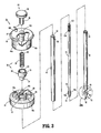
FIG. 3 is perspective view, with parts separated, of the disclosed obturator assembly; -
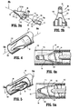
FIG. 3a is an enlarged area of detail view ofFIG. 3 ; -
FIG. 3b is a cross-sectional view taking alongline 3b-3b ofFIG. 3a ; -
FIG. 4 is a perspective view, partially shown in section, of an shield nose of the obturator assembly in a retracted position within a safety shield of the obturator assembly; -
FIG. 4a is a cross sectional view taken alongline 4a-4a ofFIG. 4 ; -
FIG. 5 is a perspective view, partially shown in section, of the shield nose with a cutting blade of the obturator tip in an extended position; -
FIG. 5a is a cross-sectional view taken alongline 5a-5a ofFIG. 5 ; -
FIG. 6 is a cross-sectional view of the trocar assembly ofFIG. 1 ; -
FIG. 7 is an enlarged area of detail view ofFIG. 6 ; -
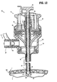
FIG. 8 is enlarged area of detail view ofFIG. 6 ; -
FIG. 9 is a cross-sectional view of the trocar assembly, positioned adjacent tissue, illustrating extension of the cutting blade within the shield nose; -
FIG. 10 is a cross-sectional view of the trocar assembly during initial urging of the trocar assembly against the tissue to retract the safety shield; -
FIG. 11 is a cross-sectional view of the trocar assembly during penetration of the tissue by the shield nose and cutting blade; and -
FIG. 12 is a perspective view of the trocar assembly after penetration of the tissue and advancement of the safety shield to cover the cutting blade. - An embodiment of the presently disclosed obturator assembly will now be described in detail with reference to the drawings wherein like numerals designate identical or corresponding elements in each of the several views. As is common in the art, the term 'proximal" refers to that part or component closer to the user or operator, i.e. surgeon or physician, while the term "distal" refers to that part or component further away from the user.
- Referring to
FIGS. 1 and 2 , there is disclosed atrocar assembly 10 including acannula assembly 12 and anobturator assembly 14 positioned throughcannula assembly 12.Cannula assembly 12 provides an access port for various surgical instruments into the body as well as a conduit for a source of insuffulation fluid to insufflate the body to create a working cavity. - With reference to
FIG. 2 ,cannula assembly 12 includes acannula housing 16 andelongate cannula sleeve 18 extending distally fromcannula housing 16.Cannula housing 16 andcannula sleeve 18 define athroughbore 20 which extends from aproximal end 22 ofcannula housing 16 to adistal end 24 ofcannula sleeve 18. Acheck valve 26 is provided oncannula housing 16 to receive a source of insuffulation fluid for passage into the body of a patient.Cannula housing 16 is additionally provided with a pair ofsuture wings cannula assembly 12 to the body of a patient. Specifically,suture wings respective slots 32a-c and 34a-c for receipt of lengths of suture material to securecannula assembly 12 to the patient's body. -
Obturator assembly 14 generally includes anobturator housing 38 and anelongate safety shield 40 extending distally from, and movably mounted within,obturator housing 38.Safety shield 40 is provided to automatically cover a cutting device associated with obturator assembly 14 (as described in more detail hereinbelow) once the cutting device has penetrated the body of a patient to prevent puncturing of underlying organs the wall of the patient punctured. - Referring now to
FIG. 3 ,obturator housing 38 includes anupper housing 42 and alower housing 44. A plurality oftabs 46a-c are provided onlower housing 44 and engage a corresponding plurality ofslots 48a-c to hold upper housing and 42 andlower housing 44 together. As noted hereinabove,safety shield 40 is movably mounted withinobturator housing 38. Adriver 50 is movably mounted withinupper housing 42 andlower housing 44 and is affixed to aproximal end 52 ofsafety shield 40. Specifically, adistal end 54 ofdriver 50 is affixed toproximal end 52 of safety shield 40 (seeFIG. 8 ).Safety shield 40 passes through ahole 56 formed inlower housing 44. Aspring 58 is provided withinobturator housing 38 tobias safety shield 40 distally relative toobturator housing 38.Spring 58 engages aproximal end 60 ofdriver 50. Aproximal end 62 ofspring 58 abuts asupport 64 formed inupper housing 42. In order to control the movement ofdriver 50 withinobturator housing 38, aguide 66 is provided onlower housing 44 and includes alongitudinally extending slot 68.Driver 50 is provided with atab 70 which rides withinslot 68. Thus, guide 66 controls the longitudinal motion ofdriver 50 withinobturator housing 38. - In order to puncture tissue, such as, for example, the wall of a body cavity,
obturator assembly 14 is provided with anelongate obturator member 72 having acutting blade 74 positioned on adistal end 76 ofobturator member 72. A pair of longitudinally extendingarms distal end 76 ofobturator member 72 to securecutting blade 74 thereon. Ashield nose 80 and asupport tube 82 are associated withobturator assembly 14 and are provided to shieldblade 74 when not in use. Aproximal end 84 ofshield nose 80 is affixed to adistal end 86 ofsupport tube 82 by any of various known means, such as, for example, crimping, welding, gluing, etc. Aproximal end 88 ofsupport tube 82 is fixedly secured to support 64 inupper housing 42. -
Shield nose 80 is provided with atruncated cavity 90 for receipt of cuttingblade 74.Shield nose 80 is further provided with ablunt tip 92 to prevent injury to organs underlying the wall of a body cavity during insertion therethrough. - In order to move
obturator member 74 withinsupport tube 82, and thus move cuttingblade 74 withinshield nose 80, aplunger 94 is provided throughupper housing 42.Plunger 94 includes ahandle 96 and atube 98 extending distally fromhandle 96.Tube 98 extends through aplunger hole 100 formed withinupper housing 42. Aproximal end 102 is affixed within abore 104 formed withintube 98. Aspring 106 is provided aboutproximal end 102 ofobturator member 72 to biasobturator member 72 within support to 82. Thus, cuttingblade 74 is biased proximally withintruncated cavity 90 ofshield nose 80. - It should be noted that, while
support tube 82 andshield nose 80 are illustrated as being fixed relative toobturator housing 38 andobturator member 72 and cuttingblade 64 are disclosed as being movable relative toobturator housing 38, it is within the contemplated scope of the present disclosure thatobturator member 72 and cuttingblade 64 may be fixed relative toobturator housing 38 andshield nose 80 andsupport tube 82 movably mounted relative toobturator housing 38. In this situation, tissue pressure againstshield nose 80 will allowshield nose 80 andsupport tube 82 to move proximally, against the bias ofspring 106, relative to cuttingblade 64 to expose cuttingblade 64 to tissue. Upon the release of pressure againstshield nose 80,shield nose 80 than advances distally against the bias ofspring 106 to go cover and shield cuttingblade 64 from exposure to underlying tissues. - In certain situations, it is desirable to provide electrocautery features to
obturator assembly 14 and, specifically to cuttingblade 74. Thus, anelectrical conduit 108 is provided onupper housing 42 and is in electrical connection withobturator member 72 as described in more detail hereinbelow. Where electrocautery features are desired,obturator member 72 may be formed of a conductive material or, may be formed of a non-conductive material having a conductive inner core for transmission of electrical power to cuttingblade 74. - Referring now to
FIGS. 3a and 3b ,shield nose 80 includes a conical,concave center section 110 extending proximally fromblunt tip 92.Shield nose 80 additionally includes a generally cylindricalproximal end 112. As noted hereinabove,shield nose 80 is provided with atruncated cavity 90 for receipt of cuttingblade 64. Specifically,truncated cavity 90 generally includes acylindrical center portion 114 which intersects aplanner portion 116.Cylindrical portion 114 is configured to receivedistal end 76 andarms obturator member 72 whileplanner portion 116 receives and supports cuttingblade 64. A pair ofslots side surface 122 of conicalconcave center section 110 ofshield nose 80. - Referring specifically to
FIG. 3a , cuttingblade 64 is generally planner and includes a pair of sharp convexcutting side edges blade 64 terminates in a blunt atraumatictruncated tip 128. - Referring to
FIG. 4a ,shield nose 80 is illustrated within abore 130 ofsafety shield 40. Specifically, in the assembled condition,shield nose 80 is initially positioned withinbore 130 at adistal end 132 ofsafety shield 40. - Referring to
FIGS. 4 and 4a , when cuttingblade 64 is in a proximal-most position withinshield nose 80, cuttingside edges planner portion 116 oftruncated cavity 90. Thus, cuttingside edges blade 64 is in the proximal most position withintruncated cavity 90 ofshield nose 80. - Similarly, with reference to
FIGS. 5 and 5a , when cuttingblade 64 is in a distal most position withinshield nose 80, cuttingside edges blade 64 project throughslots side surface 122 of conicalconcave center section 110 ofshield nose 80 and are in a position to cut tissue. - Referring now to
FIG. 6 , as noted hereinabove,cannula assembly 12 includes avalve 26 for receipt of a source of insuffulation fluid. In order to prevent the escape of insuffulation fluid out ofcannula assembly 12,cannula assembly 12 is provided with aduckbill valve 134 located within an interior 136 ofcannula housing 16.Duckbill valve 134 is in a normally closed position and is provided to seal aboutsafety shield 40 whenobturator assembly 14 is inserted throughcannula assembly 12. - Referring for the moment to
FIGS. 6 and 7 , as noted hereinabove it is often desirable to provide an obturator assembly with electrocautery features.Cannula assembly 12 includeselectrical conduit 108. With reference toFIG. 6 ,electrical conduit 108 generally includes aconnector 138 affixed toupper housing 38 and acable 140 extending fromconnector 138 toobturator member 72. With specific reference toFIG. 7 , awire 142 extends fromcable 140 and passes throughsupport 64 inupper housing 42. Awiper 144 is affixed to wire 142 and is in electrical contact withobturator member 72. Thus, by providing a source of electrical power toelectrical conduit 108, the power is passed throughobturator member 72 to cutting blade 64 (FIG. 6 ) for providing electrocautery action on the tissue being operated upon. - With reference to
FIG. 8 , and as noted hereinabove,safety shield 40 is affixed todriver 50. Specifically,driver 50 is provided with one ormore tabs 146 which are configured to reside withinslots 148 formed inproximal end 52 ofsafety shield 40. (See alsoFIG. 3 ). - Referring now to
FIGS. 6 and9-12 , the operation oftrocar assembly 10 and, specificallyobturator assembly 14 will now be described. Referring initially toFIG. 6 , in the assembled condition oftrocar assembly 10,obturator assembly 14 is inserted throughcannula assembly 12. Specifically,safety shield 40 andobturator member 72 ofobturator assembly 14 are inserted throughcannula housing 16 andcannula sleeve 18.Duckbill valve 134 provided withininterior 136 ofcannula housing 16 seals aboutsafety shield 40.Plunger 94 is in the proximal most positioned against the bias ofspring 106 to position cuttingblade 64 in the proximal most position withinshield nose 80. As shown,shield nose 80 and cuttingblade 64 are in a proximal position withindistal end 132 ofsafety shield 40. (See alsoFIGS. 4 and 4a ). - With reference to
FIG. 9 , in use,trocar assembly 10 is positioned adjacent a tissue T such as an abdominal wall such that adistal end 150 ofsafety shield 40 abuts a body wall BW of tissue T. A cavity C exists beneath body wall BW and contains the desired organs to be operated upon (not shown). Initially,plunger 94 is depressed against the bias ofspring 106 to driveobturator member 72 distally relative to supporttube 82. Cuttingblade 64 it is advance to the proximal most positioned withinshield nose 80 to exposeconvex cutting edges 124 at 126 of cuttingblade 64 throughshield nose 80. (See alsoFIGS. 5 and 5a ). - Referring now to
FIG. 10 , once cuttingblade 64 has been exposed throughshield nose 80,trocar assembly 10 as a whole can be advanced against body wall BW of tissue T. Specifically,distal end 150 ofsafety shield 40 engages body wall BW and is driven proximally relative toobturator housing 38 and against the bias ofspring 58. This begins to expose cuttingblade 64 to body wall BW of tissue T. As shown,blunt tip 92 ofshield nose 80 engages body wall BW. As noted hereinabove,blunt tip 92 is provided to prevent cutting of underlying tissues as cuttingblade 64 creates an incision and passes through body wall BW. - As best shown in
FIG. 11 , astrocar assembly 10 is further urged against body wall BW,convex cutting edges blade 64 cut into, and create an incision through, body wall BW of tissue T to provide access to cavity C. As noted hereinabove, it is often desirable to provide electrocautery action to cuttingblade 64 to facilitate cutting through body wall BW. Thus, by providing a source of power toelectrical conduit 108, power is passed throughcable 140 toproximal end 102 ofobturator member 72. As further noted hereinabove,obturator 72 may be formed completely of a conductive material or may be formed of a non-conductive material having a conductive inner core in electrical connection with 64. In this monopolar typesystem cutting blade 64 is energized to facilitate cutting through body wall BW and assist in cauterizing the sides of the incision therethrough. - Referring to
FIG. 12 , once cuttingblade 64 has created an incision I through body wall BW,safety shield 40 is driven through incision I due to the bias ofspring 58 againstdriver 50 connected tosafety shield 40. In this manner, exposed cuttingblade 64 is shielded from any underlying organs to prevent damage thereto. Alternatively, and or in addition to, pressure may be released fromplunger 94 to allow cuttingblade 64 to retract withinshield nose 80 due to the bias ofspring 106. In this manner, cuttingblade 64 is safely contained withinshield nose 80 to prevent damage to underlying tissues. - It will be understood that various modifications may be made to the embodiments disclosed herein. For example, as noted hereinabove, the obturator member in cutting blade may be fixed relative to the obturator housing while the shield nose and support tube bias distally relative to the cutting blade. Further, the cutting blade may assume other configurations than planer such as, for example, triangular, etc. with corresponding openings in the shield nose to allow exposure of the cutting blade. Additionally, various internal components of the obturator assembly may be formed of nonconductive materials when electrocautery features are provided to the cutting blade. Therefore, the above description should not be construed as limiting, but merely as exemplifications of particular embodiments. Those skilled in the art will envision other modifications within the scope and spirit of the claims appended hereto.
Claims (14)
- An obturator assembly comprising:an obturator housing;a support tube extending distally from the obturator housing;a shield nose affixed to a distal end of the support tube, the shield nose defining a truncated cavity and having a concave center portion;an obturator member movably mounted relative to the support tube;a cutting blade having at least one cutting edge and affixed to a distal end of the obturator member, the cutting blade movable within the truncated cavity; wherein, the shield nose has at least one slot formed through the concave center portion and in communication with the truncated cavity for allowing passage of the at least one cutting edge therethrough.
- The obturator assembly as recited in claim 1, wherein the shield nose has a blunt tip distal of the truncated cavity; or the obturator assembly as recited in claim 1, wherein the truncated cavity includes a planner portion for receipt of the cutting blade; or the obturator assembly as recited in claim 1, wherein the truncated cavity includes a cylindrical portion for receipt of the distal end of the obturator member.
- The obturator assembly as recited in claim 1, further comprising a spring positioned between the obturator housing and the obturator member, the spring biasing the obturator member proximally relative to the support tube.
- The obturator assembly as recited in claim 3, further comprising a plunger affixed to a proximal end of the obturator member.
- The obturator assembly as recited in claim 1, further comprising an electrical conduit attached to the obturator housing and in electrical connection with the cutting blade.
- The obturator assembly as recited in claim 5, wherein the obturator member is formed of an electrically conductive material.
- The obturator assembly as recited in claim 5, wherein the obturator member is formed of an electrically nonconductive material and includes an electrically conductive inner core.
- An obturator assembly comprising:an obturator housing;a support tube extending distally from the obturator housing;a shield nose affixed to a distal end of the support tube, the shield nose defining a cavity;an obturator member movably mounted relative to the support tube;a cutting blade having at least one cutting edge and affixed to a distal end of the obturator member, the cutting blade being movable within the cavity; anda safety shield movably mounted to the obturator housing.
- The obturator assembly as recited in claim 8, further comprising a spring engageable with the safety shield to bias the safety shield distally relative to the obturator housing.
- The obturator assembly as recited in claim 9, further comprising a driver engageable with the spring and affixed to a proximal end of the safety shield.
- The obturator assembly as recited in claim 11, further comprising a guide formed in the obturator housing and a tab formed on the driver and movable within the guide.
- The obturator assembly as recited in claim 8, wherein the shield nose has a concave center portion and at least one slot formed through the concave center portion and in communication therewith for allowing passage of the at least one cutting edge therethrough.
- A trocar assembly comprising;a cannula assembly including a cannula housing and a cannula sleeved extending distally from the cannula housing;an obturator assembly insertable through the cannula assembly and including;an obturator housing;a support tube extending distally from the obturator housing;a shield nose affixed to a distal end of the support tube, the shield nose defining a cavity;an obturator member movably mounted relative to the support tube;a cutting blade having at least one cutting edge and affixed to a distal end of the obturator member, the cutting blade being movable within the cavity; anda safety shield movably mounted to the obturator housing.
- The trocar assembly as recited in claim 13, wherein the cannula housing includes a valve positioned within an interior of the cannula housing such that the valve seals about the safety shield when the obturator assembly is inserted into the cannula assembly.
Applications Claiming Priority (2)
| Application Number | Priority Date | Filing Date | Title |
|---|---|---|---|
| US6014708P | 2008-06-10 | 2008-06-10 | |
| US12/432,913 US8911463B2 (en) | 2008-06-10 | 2009-04-30 | Bladed/bladeless obturator for use in a surgical trocar assembly |
Publications (1)
| Publication Number | Publication Date |
|---|---|
| EP2133032A1 true EP2133032A1 (en) | 2009-12-16 |
Family
ID=41066629
Family Applications (1)
| Application Number | Title | Priority Date | Filing Date |
|---|---|---|---|
| EP09251393A Withdrawn EP2133032A1 (en) | 2008-06-10 | 2009-05-27 | A bladed/bladeless obturator for use in a surgical trocar assembly |
Country Status (5)
| Country | Link |
|---|---|
| US (1) | US8911463B2 (en) |
| EP (1) | EP2133032A1 (en) |
| JP (1) | JP5424722B2 (en) |
| AU (1) | AU2009202007B2 (en) |
| CA (1) | CA2665860A1 (en) |
Cited By (1)
| Publication number | Priority date | Publication date | Assignee | Title |
|---|---|---|---|---|
| EP2233092A1 (en) * | 2009-03-27 | 2010-09-29 | Tyco Healthcare Group LP | Integral insufflation valve |
Families Citing this family (34)
| Publication number | Priority date | Publication date | Assignee | Title |
|---|---|---|---|---|
| EP2117446B1 (en) * | 2007-02-20 | 2017-04-26 | Covidien LP | Surgical apparatus with annular penetrator |
| US8353874B2 (en) * | 2010-02-18 | 2013-01-15 | Covidien Lp | Access apparatus including integral zero-closure valve and check valve |
| US8961552B2 (en) | 2010-09-21 | 2015-02-24 | Covidien Lp | Bladeless obturators and bladeless obturator members |
| CA2872939C (en) * | 2012-05-09 | 2018-03-06 | EON Surgical Ltd. | Laparoscopic port |
| US10022148B2 (en) | 2012-12-27 | 2018-07-17 | Covidien Lp | Two-shot molded optical obturator |
| DE102013100605A1 (en) | 2013-01-22 | 2014-07-24 | Rg Mechatronics Gmbh | Robotic system and method for controlling a robotic system for minimally invasive surgery |
| US9271752B2 (en) * | 2013-03-13 | 2016-03-01 | Swan Valley Medical Incorporated | Method and apparatus for placing a cannula in a bladder |
| US20150057680A1 (en) | 2013-08-21 | 2015-02-26 | Crh Medical Corporation | Elastic band ligation device with anti-pinch feature and method for treatment of hemorrhoids |
| US9545264B2 (en) * | 2014-06-06 | 2017-01-17 | Surgiquest, Inc. | Trocars and obturators |
| US10391271B2 (en) * | 2015-11-17 | 2019-08-27 | David Lott | Apparatus for performing a cricothyrotomy/tracheotomy and method therefor |
| US10945760B2 (en) * | 2016-06-10 | 2021-03-16 | Fresenius Kabi Deutschland Gmbh | Cannulation device |
| WO2018075694A1 (en) * | 2016-10-18 | 2018-04-26 | Piper Access, Llc | Intraosseous access devices, systems, and methods |
| EP4245352B1 (en) | 2016-10-27 | 2026-07-01 | C. R. Bard, Inc. | INTRAOSSARY ACCESS DEVICE |
| ES2880417T3 (en) | 2017-03-07 | 2021-11-24 | Piper Access Llc | Safety protection elements for elongated instruments and related systems |
| US10201396B2 (en) | 2017-03-07 | 2019-02-12 | Carefusion 2200, Inc. | Trocar assembly with a cleaning element for use during a laparoscopic procedure |
| US10368905B2 (en) | 2017-03-07 | 2019-08-06 | Carefusion 2200, Inc. | Trocar assembly with a cleaning element for use during a laparoscopic procedure |
| US10398296B2 (en) | 2017-03-07 | 2019-09-03 | Carefusion 2200, Inc. | Trocar assembly with a cleaning element for use during a laparoscopic procedure |
| WO2018165339A1 (en) | 2017-03-10 | 2018-09-13 | Piper Access, Llc. | Securement devices, systems, and methods |
| WO2018222767A1 (en) | 2017-05-31 | 2018-12-06 | Carefusion 2200, Inc. | Trocar assembly with a cleanning element for use during a laparoscopic procedure |
| ES2953372T3 (en) | 2018-02-20 | 2023-11-10 | Piper Access Llc | Drilling devices and related methods |
| CN212879505U (en) | 2019-09-27 | 2021-04-06 | 巴德阿克塞斯系统股份有限公司 | Intraosseous access device |
| CN112568975B (en) | 2019-09-27 | 2025-04-11 | 巴德阿克塞斯系统股份有限公司 | Constant torque intraosseous access device and method thereof |
| EP4031017B1 (en) | 2019-09-27 | 2024-10-30 | Bard Access Systems, Inc. | Step needle for intraosseous access device |
| CN112568961B (en) | 2019-09-27 | 2025-07-01 | 巴德阿克塞斯系统股份有限公司 | Self-advancing feature of intraosseous devices |
| RU198692U1 (en) * | 2019-12-31 | 2020-07-22 | Общество с ограниченной ответственностью "Специальная и медицинская техника" (ООО "Спецмедтехника") | Intraosseous access device |
| CN215306397U (en) | 2020-02-28 | 2021-12-28 | 巴德阿克塞斯系统股份有限公司 | Access assembly for use with an intraosseous access device |
| CN215349256U (en) | 2020-04-21 | 2021-12-31 | 巴德阿克塞斯系统股份有限公司 | Intraosseous Access Devices and Access Devices |
| EP4606330A3 (en) | 2020-06-03 | 2025-11-05 | Bard Access Systems, Inc. | Intraosseous device including a sensing obturator |
| US12226123B2 (en) | 2020-07-17 | 2025-02-18 | Bard Access Systems, Inc. | Safety mechanism |
| CN114098918B (en) | 2020-08-25 | 2025-12-12 | 巴德阿克塞斯系统股份有限公司 | Angled intraosseous access system |
| US12551236B2 (en) | 2020-09-01 | 2026-02-17 | Bard Access Systems, Inc. | Retractable intraosseous access system |
| EP4203820B1 (en) | 2020-09-09 | 2025-01-29 | Bard Access Systems, Inc. | Aspiration apparatus for intraosseous access system |
| EP4287952A1 (en) | 2021-02-08 | 2023-12-13 | Bard Access Systems, Inc. | Intraosseous modular power |
| EP4346652A4 (en) | 2021-05-25 | 2025-04-02 | Sackett, Samuel, Gregory | SAFETY TROCAR SET |
Citations (8)
| Publication number | Priority date | Publication date | Assignee | Title |
|---|---|---|---|---|
| US5127909A (en) | 1990-04-05 | 1992-07-07 | United States Surgical Corporation | Flapper valve for an insufflation cannula assembly |
| US5423848A (en) | 1992-04-14 | 1995-06-13 | Olympus Optical Co., Ltd. | Trocar |
| US5607440A (en) | 1994-05-06 | 1997-03-04 | Endoscopic Concepts, Inc. | Trocar with lockable shield |
| US5697947A (en) | 1993-09-07 | 1997-12-16 | Invamed, Inc. | Trocar obturator including a removable knife |
| US5779680A (en) | 1991-11-27 | 1998-07-14 | Yoon; Inbae | Retractable safety needle instrument with movable safety member |
| WO2001034228A1 (en) | 1999-11-12 | 2001-05-17 | Embol-X, Inc. | Medical device introducer and obturator and methods |
| US6319266B1 (en) | 2000-03-16 | 2001-11-20 | United States Surgical Corporation | Trocar system and method of use |
| EP1738700A1 (en) | 2005-06-30 | 2007-01-03 | Tyco Healthcare Group Lp | Thin bladed obturator with curved surfaces |
Family Cites Families (75)
| Publication number | Priority date | Publication date | Assignee | Title |
|---|---|---|---|---|
| US4535773A (en) | 1982-03-26 | 1985-08-20 | Inbae Yoon | Safety puncturing instrument and method |
| US4601710B1 (en) | 1983-08-24 | 1998-05-05 | United States Surgical Corp | Trocar assembly |
| US4654030A (en) | 1986-02-24 | 1987-03-31 | Endotherapeutics | Trocar |
| US5030206A (en) | 1986-10-17 | 1991-07-09 | United States Surgical Corporation | Trocar |
| US4902280A (en) | 1986-10-17 | 1990-02-20 | United States Surgical Corporation | Trocar |
| US4931042A (en) | 1987-10-26 | 1990-06-05 | Endotherapeutics | Trocar assembly with improved latch |
| US5215526A (en) | 1988-07-06 | 1993-06-01 | Ethicon, Inc. | Safety trocar |
| GB8816033D0 (en) | 1988-07-06 | 1988-08-10 | Ethicon Inc | Improved safety trocar |
| US5217441A (en) | 1989-08-15 | 1993-06-08 | United States Surgical Corporation | Trocar guide tube positioning device |
| US5114407A (en) | 1990-08-30 | 1992-05-19 | Ethicon, Inc. | Safety mechanism for trocar |
| US5318580A (en) | 1990-09-11 | 1994-06-07 | Origin Medsystems, Inc. | Retractable trocar |
| US5116353B1 (en) | 1990-10-05 | 1996-09-10 | Digital Voice Systems Inc | Safety trocar |
| AU644900B2 (en) | 1990-10-05 | 1993-12-23 | United States Surgical Corporation | Safety trocar |
| US5226426A (en) | 1990-12-18 | 1993-07-13 | Inbae Yoon | Safety penetrating instrument |
| US5350393A (en) | 1992-01-06 | 1994-09-27 | Inbae Yoon | Safety trocar penetrating instrument |
| US5645556A (en) | 1990-12-18 | 1997-07-08 | Yoon; Inbae | Safety penetrating instrument with triggered penetrating member retraction and single or multiple safety member protrusion |
| US5578053A (en) | 1993-06-24 | 1996-11-26 | Yoon; Inbae | Safety needle instrument having a triggered safety member |
| US5645557A (en) | 1990-12-18 | 1997-07-08 | Yoon; Inbae | Safety penetrating instrument with triggered penetrating member retraction and safety member protrusion |
| US5431635A (en) | 1990-12-18 | 1995-07-11 | Yoon; Inbae | Safety penetrating instrument having a triggered safety member for establishing an endoscopic portal in an anatomical cavity wall |
| US5827315A (en) | 1994-01-04 | 1998-10-27 | Yoon; Inbae | Safety penetrating instrument with penetrating member protected after penetration to predetermined depth |
| US5104382A (en) | 1991-01-15 | 1992-04-14 | Ethicon, Inc. | Trocar |
| US5474539A (en) | 1991-02-07 | 1995-12-12 | Origin Medsystems, Inc. | Trocar with retracting tip |
| US5152754A (en) | 1991-02-15 | 1992-10-06 | Minnesota Mining And Manufacturing Company | Trocar |
| US5295993A (en) | 1991-04-30 | 1994-03-22 | United States Surgical Corporation | Safety trocar |
| US5591186A (en) | 1991-05-22 | 1997-01-07 | Wurster; Helmut | Self-cutting trocar |
| US5645076A (en) | 1991-08-14 | 1997-07-08 | Yoon; Inbae | Automatic retractable safety penetrating instrument |
| US5158552A (en) | 1991-11-04 | 1992-10-27 | American Cyanamid Company | Safety trocar instrument having a retractable trocar actuated by relief of pressure on the trocar point |
| US5312354A (en) | 1991-11-04 | 1994-05-17 | American Cyanamid Company | Safety trocar instrument having a retractable point actuated by a trigger sleeve |
| US5573511A (en) * | 1991-11-27 | 1996-11-12 | Yoon; Inbae | Retractable safety penetrating instrument with safety probe |
| US5441513A (en) | 1992-03-12 | 1995-08-15 | United States Surgical Corporation | Retracting tip trocar assembly |
| US5248298A (en) | 1992-04-16 | 1993-09-28 | Ethicon, Inc. | Insert for shielded trocar |
| US5290243A (en) | 1992-07-16 | 1994-03-01 | Technalytics, Inc. | Trocar system |
| US5246425A (en) | 1992-09-21 | 1993-09-21 | Daniel Hunsberger | Trocar and cannula assembly |
| US5275583A (en) | 1992-10-05 | 1994-01-04 | Lawrence Crainich | Trocar assembly with independently acting shield means |
| US5356421A (en) | 1992-10-07 | 1994-10-18 | United States Surgical Corporation | Safety trocar with locking handles |
| US5372588A (en) | 1992-11-24 | 1994-12-13 | Farley; Kevin | Trocar having blunt tip |
| US5314417A (en) | 1992-12-22 | 1994-05-24 | Ethicon, Inc. | Safety trocar |
| US5263937A (en) | 1993-02-11 | 1993-11-23 | Shipp John I | Trocar with profile to reduce insertion force |
| US5387197A (en) | 1993-02-25 | 1995-02-07 | Ethicon, Inc. | Trocar safety shield locking mechanism |
| US5462532A (en) | 1993-03-17 | 1995-10-31 | Origin Medsystems, Inc. | Trocar with safety sensing sleeve |
| US5364372A (en) | 1993-03-29 | 1994-11-15 | Endoscopic Concepts, Inc. | Trocar and cannula |
| US5868773A (en) | 1993-03-29 | 1999-02-09 | Endoscopic Concepts, Inc. | Shielded trocar with safety locking mechanism |
| US5346459A (en) | 1993-04-14 | 1994-09-13 | Minnesota Mining And Manufacturing Company | Trocar |
| US5417705A (en) | 1993-05-14 | 1995-05-23 | Habley Medical Technology Corp. | Obturator with rotating, resettable safety shield |
| US5437643A (en) | 1993-05-17 | 1995-08-01 | Ethicon, Inc. | Safety interposer for surgical instruments |
| DK0705077T3 (en) | 1993-05-28 | 1999-01-25 | Origin Medsystems Inc | Towers with retractable tip and feel |
| US5584848A (en) * | 1993-06-24 | 1996-12-17 | Yoon; Inbae | Safety penetrating instrument with penetrating member, safety member and cannula moving during penetration and triggered safety member protrusion |
| US5411515A (en) | 1993-07-29 | 1995-05-02 | Habley Medical Technology Corporation | Obturator with rotating, self-locking and resettable safety shield |
| US5364365A (en) | 1993-08-30 | 1994-11-15 | Surgin Surgical Instrumentation, Inc. | Safety device for laparoscopic instruments |
| US5467762A (en) | 1993-09-13 | 1995-11-21 | United States Surgical Corporation | Optical trocar |
| US5538509A (en) | 1994-01-31 | 1996-07-23 | Richard-Allan Medical Industries, Inc. | Trocar assembly |
| CA2149290C (en) | 1994-05-26 | 2006-07-18 | Carl T. Urban | Optical trocar |
| US5522833A (en) | 1994-08-29 | 1996-06-04 | Ethicon Endo-Surgery, Inc. | Retractable obturator for a trocar |
| CA2168694A1 (en) | 1995-03-20 | 1996-09-21 | Wayne P. Young | Trocar assembly with electrocautery penetrating tip |
| US5807338A (en) | 1995-10-20 | 1998-09-15 | United States Surgical Corporation | Modular trocar system and methods of assembly |
| US5674237A (en) | 1996-03-06 | 1997-10-07 | Ott; Henryk | Safety trocar |
| US5669885A (en) | 1996-05-14 | 1997-09-23 | United States Surgical Corporation | Trocar assembly with spring-loaded mechanism |
| US6117153A (en) | 1996-10-03 | 2000-09-12 | Interventional Technologies, Inc. | Neovascularization catheter |
| US5843115A (en) * | 1996-10-28 | 1998-12-01 | Morejon; Orlando | Trocar insertion device |
| US5984941A (en) | 1997-02-13 | 1999-11-16 | Endoscopic Concepts, Inc. | Trocar |
| US6017356A (en) | 1997-09-19 | 2000-01-25 | Ethicon Endo-Surgery Inc. | Method for using a trocar for penetration and skin incision |
| US5904699A (en) | 1997-09-19 | 1999-05-18 | Ethicon Endo-Surgery, Inc. | Trocar for penetration and skin incision |
| US6036711A (en) | 1998-02-18 | 2000-03-14 | United States Surgical Corporation | Reusable cannula |
| IL128989A0 (en) | 1999-03-15 | 2000-02-17 | Popov Sergey | Safety trocar assembly |
| US6077284A (en) | 1999-05-17 | 2000-06-20 | Piraka; Hadi A. | Laparoscopic scalpel |
| DE19931110A1 (en) | 1999-07-06 | 2001-01-25 | Ekra Eduard Kraft Gmbh | Print head for ejecting a hot liquid medium and method for producing a joint comprising metallic solder |
| US6270501B1 (en) | 1999-11-08 | 2001-08-07 | The Regents Of The University Of Michigan | Surgical method and apparatus and cannulated scalpel for use therein |
| US6884253B1 (en) | 2000-05-16 | 2005-04-26 | Taut, Inc. | Penetrating tip for trocar assembly |
| WO2002001998A2 (en) | 2000-05-16 | 2002-01-10 | Taut, Inc. | Penetrating tip for trocar assembly |
| EP1307151B1 (en) | 2000-08-08 | 2007-11-28 | Tyco Healthcare Group Lp | Molded trocar latch |
| US6656198B2 (en) * | 2001-06-01 | 2003-12-02 | Ethicon-Endo Surgery, Inc. | Trocar with reinforced obturator shaft |
| MXPA05009572A (en) * | 2003-03-06 | 2005-11-17 | Erblan Surgical Inc | Insufflator and method of use. |
| US7824327B2 (en) * | 2005-04-12 | 2010-11-02 | Tyco Healthcare Group Llp | Optical trocar with scope holding assembly |
| US8167842B2 (en) | 2005-09-21 | 2012-05-01 | Mayo Foundation For Medical Education And Research | Introducer apparatus with cutting edges |
| EP2117446B1 (en) * | 2007-02-20 | 2017-04-26 | Covidien LP | Surgical apparatus with annular penetrator |
-
2009
- 2009-04-30 US US12/432,913 patent/US8911463B2/en not_active Expired - Fee Related
- 2009-05-12 CA CA002665860A patent/CA2665860A1/en not_active Abandoned
- 2009-05-21 AU AU2009202007A patent/AU2009202007B2/en not_active Ceased
- 2009-05-27 EP EP09251393A patent/EP2133032A1/en not_active Withdrawn
- 2009-06-02 JP JP2009133551A patent/JP5424722B2/en not_active Expired - Fee Related
Patent Citations (8)
| Publication number | Priority date | Publication date | Assignee | Title |
|---|---|---|---|---|
| US5127909A (en) | 1990-04-05 | 1992-07-07 | United States Surgical Corporation | Flapper valve for an insufflation cannula assembly |
| US5779680A (en) | 1991-11-27 | 1998-07-14 | Yoon; Inbae | Retractable safety needle instrument with movable safety member |
| US5423848A (en) | 1992-04-14 | 1995-06-13 | Olympus Optical Co., Ltd. | Trocar |
| US5697947A (en) | 1993-09-07 | 1997-12-16 | Invamed, Inc. | Trocar obturator including a removable knife |
| US5607440A (en) | 1994-05-06 | 1997-03-04 | Endoscopic Concepts, Inc. | Trocar with lockable shield |
| WO2001034228A1 (en) | 1999-11-12 | 2001-05-17 | Embol-X, Inc. | Medical device introducer and obturator and methods |
| US6319266B1 (en) | 2000-03-16 | 2001-11-20 | United States Surgical Corporation | Trocar system and method of use |
| EP1738700A1 (en) | 2005-06-30 | 2007-01-03 | Tyco Healthcare Group Lp | Thin bladed obturator with curved surfaces |
Cited By (2)
| Publication number | Priority date | Publication date | Assignee | Title |
|---|---|---|---|---|
| EP2233092A1 (en) * | 2009-03-27 | 2010-09-29 | Tyco Healthcare Group LP | Integral insufflation valve |
| US8070730B2 (en) | 2009-03-27 | 2011-12-06 | Tyco Healthcare Group Lp | Integral insufflation valve |
Also Published As
| Publication number | Publication date |
|---|---|
| JP5424722B2 (en) | 2014-02-26 |
| US8911463B2 (en) | 2014-12-16 |
| US20090306697A1 (en) | 2009-12-10 |
| JP2009297509A (en) | 2009-12-24 |
| AU2009202007A1 (en) | 2009-12-24 |
| AU2009202007B2 (en) | 2014-07-24 |
| CA2665860A1 (en) | 2009-12-10 |
Similar Documents
| Publication | Publication Date | Title |
|---|---|---|
| US8911463B2 (en) | Bladed/bladeless obturator for use in a surgical trocar assembly | |
| EP2311394B1 (en) | Cannulated arthroscopic knife | |
| US5674237A (en) | Safety trocar | |
| EP2044894B1 (en) | Bladeless obturator for use in a surgical trocar assembly | |
| US9999439B2 (en) | Laparoscopic scalpel and method for use | |
| US6030402A (en) | Apparatus and methods for the penetration of tissue, and the creation of an opening therein | |
| US6960164B2 (en) | Obturator tip for a trocar | |
| EP2391286B1 (en) | Transapical mini-introducer homeostasis valve and punch | |
| US5984941A (en) | Trocar | |
| US8257316B2 (en) | Surgical portal apparatus with variable adjustment | |
| EP3174484B1 (en) | Needlescopic scissor end effector | |
| US20040230155A1 (en) | Insufflator and method of use | |
| KR20040104489A (en) | Safety trocar with progressive cutting tip guards and gas jet tissue deflector | |
| CN1358103A (en) | Safety trocar with progressive cutting tip and air jet tissue deflector | |
| WO1994022376A1 (en) | Handle for laparoscopic instrument | |
| AU2005244553A1 (en) | Duckbill seal protector | |
| EP3928725B1 (en) | Obturator having a distal electrode | |
| AU2004220625A1 (en) | Insufflator and method of use | |
| EP1563797A2 (en) | Safety trocar with progressive cutting tip guards and gas jet tissue deflector | |
| KR200444387Y1 (en) | End structure of trocar incision bar | |
| JPH05317326A (en) | Puncture needle |
Legal Events
| Date | Code | Title | Description |
|---|---|---|---|
| PUAI | Public reference made under article 153(3) epc to a published international application that has entered the european phase |
Free format text: ORIGINAL CODE: 0009012 |
|
| AK | Designated contracting states |
Kind code of ref document: A1 Designated state(s): AT BE BG CH CY CZ DE DK EE ES FI FR GB GR HR HU IE IS IT LI LT LU LV MC MK MT NL NO PL PT RO SE SI SK TR |
|
| 17P | Request for examination filed |
Effective date: 20100607 |
|
| 17Q | First examination report despatched |
Effective date: 20100707 |
|
| RAP1 | Party data changed (applicant data changed or rights of an application transferred) |
Owner name: COVIDIEN LP |
|
| STAA | Information on the status of an ep patent application or granted ep patent |
Free format text: STATUS: THE APPLICATION IS DEEMED TO BE WITHDRAWN |
|
| 18D | Application deemed to be withdrawn |
Effective date: 20171201 |