EP2132976A1 - Draper belt construction to control translation - Google Patents
Draper belt construction to control translation Download PDFInfo
- Publication number
- EP2132976A1 EP2132976A1 EP09162300A EP09162300A EP2132976A1 EP 2132976 A1 EP2132976 A1 EP 2132976A1 EP 09162300 A EP09162300 A EP 09162300A EP 09162300 A EP09162300 A EP 09162300A EP 2132976 A1 EP2132976 A1 EP 2132976A1
- Authority
- EP
- European Patent Office
- Prior art keywords
- rollers
- conveyor belt
- frame
- assembly
- ridge
- Prior art date
- Legal status (The legal status is an assumption and is not a legal conclusion. Google has not performed a legal analysis and makes no representation as to the accuracy of the status listed.)
- Granted
Links
Images



Classifications
-
- A—HUMAN NECESSITIES
- A01—AGRICULTURE; FORESTRY; ANIMAL HUSBANDRY; HUNTING; TRAPPING; FISHING
- A01D—HARVESTING; MOWING
- A01D57/00—Delivering mechanisms for harvesters or mowers
- A01D57/20—Delivering mechanisms for harvesters or mowers with conveyor belts
Definitions
- the present invention relates to floating platform and draper -type headers for agricultural combines.
- An agricultural combine is a large machine used to harvest a variety of crops from a field.
- a header at the front of the combine cuts ripened crop from the field.
- a feederhouse supporting the header transfers the crop material into the combine.
- Threshing and separating assemblies within the combine remove grain from the crop material and transfer the clean g rain to a grain tank for temporary holding.
- An unloading auger transfers the clean grain from the grain tank to a truck or grain cart for transport, or to another receiving bin for holding.
- Draper headers are header types commonly used when harvesting crops such as small grains, peas, lentils, and rice.
- Such draper headers comprise a cutter bar and two or more conveying transversely moving belts arranged in a forward direction behind the cutter bar that convey the cut crop towards the center of the header, where it is fed towards the rear by another conveyor belt assembly that feeds the crop towards a rear outlet of the header and to a feederhouse of the combine.
- a harvesting operati on with this header type it is desirable to maintain a cutting height as low as possible to the ground in order to collect substantially the entire ripe crop from the field.
- combines typically employ a header float system or a terrain following system to enable the header to follow the ground over changing terrain without gouging or digging into the soil.
- Published patent application US 2005/022491 A1 describes a platform header for a combine with a rigid frame, a cutter bar and three belts arranged side by side for conveying the crop rearward to a transverse auger.
- the belts comprise at their lateral ends inwardly extending wedges neighboring the side walls of the deflection rollers, in order to prevent the belt from running off the rollers.
- Published patent application US 2006/254241 A1 describes a similar platform header in which cover plates between adjacent belts are located in lower positions as the lateral end of the belt, in order to prevent crop or residues from entering between the cover and the belt.
- a draper platform includes a frame, a cutter bar, at least one conveyor assembly with two rollers and a conveyor belt surrounding both rollers. E ach of the rollers are mounted to a respective support frame that is independently pivotally mounted to the frame around a transverse axis at its rear end.
- An assembly for guiding the conveyor belt on the rollers is provided. It includes a ridge on an interior side of the conveyor belt and a groove within the roller. The ridge and the groove are provided in the vicinity of the rear end of the rollers.
- Figure 1 illustrates a self-propelled combine 10 commonly used in a grain farming operation to harvest a variety of crops from a field.
- An onboard engine (not shown) powers the combine 10, while ground eng aging wheels 14 support and propel the machine.
- An operator controls the combine 10 from an operator's station located in a cab 16 at the front of the machine.
- a feederhouse 20 pivotally attaches at the front of the combine 10, supporting a header 22 removably attached to the front of the feed erhouse 20.
- a pair of lift cylinders 24 support and articulate the feederhouse 20 from the combine 10, enabling the raising and lowering of the header 22 relative to the ground.
- th e combine 10 moves forward through the field with the header 22 lowered to a working height.
- the header 22 cuts and transfers crop material to the feederhouse 20, which in turn transfers the crop material into the combine 10.
- thres hing and separating assemblies 26 remove grain from the non-grain crop material and transfer it to a grain tank 28 for temporary holding. Crop material other than grain exits from the rear of the combine 10.
- An unloading auger 30 transfers the grain from the grain tank 28 to a truck or grain cart for transport, or to another receiving bin for holding.
- Figure 2 shows a perspective view of the header 22, which is a draper type header and includes a frame 32 supporting a cutter bar 34 extending over the entire width of header 22, a first transverse conveyor belt assembly 36, a second transverse conveyor belt assembly 38, a third transverse conveyor belt assembly 40, a fourth transverse conveyor belt assembly 42 and a fifth conveyor belt assembly 44.
- first and second conveyor belt assemblies 36, 38 convey the crop cut by the cutter bar 34 to the left and thus towards the center of header 22
- the third and fourth conveyor belt assemblies 40, 42 convey the crop cut by the cutter bar 34 to the right and thus towards the center of header 22, where it is fed by the fifth conveyor belt assembly 44 and an upper transverse drum conveyor 48 with outwardly extending fingers towards a rear exit opening 46 of frame 32 and thus to the feederhouse 20.
- a reel assembly 50 shown in Figure 1 is also supported on frame 32 and moves crop standing on the field towards the cutter bar 34.
- the frame 32 comprises vertically extending rear cover sheets 52 mounted behind the conveyor belt assemblies 36 -42, and side walls 54 at both ends.
- the frame 32 includes a transverse, cylindri cal beam 56 with a circular cross section.
- Beam 56 extends outward from the center portion of the frame of the header 22.
- the rear cover sheets 52 and the side walls 54 are directly mounted to beam 56, which is supported on the feederhouse 20 by a supporting assembly 62 supporting beam 56 on top of the front portion of the feederhouse 20.
- the beam 56 further supports a number of forwardly extending support frames 58 distributed over the width of beam 56.
- the support frames 58 are pivotally mounted to the be am 56 around the longitudinal axis 56 beam 56 by way of rings 60 enclosing beam 56.
- the rings 60 are mounted to a respective support frame 58, as shown in Figure 4 .
- the support frames 58 carry on their front ends the cutter bar 34 as well as lower ground engaging skids 64 and upper crop guides 66 having a vertical front wall and an upper, horizontal wall extending towards the rear beyond the front edges of the conveyor belt assemblies 36 -42.
- the right half of the frame 32 of header 22 comprises in total eight support frames 58.
- the outermost support frame 58 mounts a roller 68, while the two succeeding support frames 58 mount stabilization rods 70.
- the next (fourth seen from the right end) support frame 58 mounts two rollers 68, while the three succeeding support frames 58 also mount stabilization rods 70.
- the two rollers 68 of the fourth support frame 58 are connected by way of a gearbox 74 to a hydraulic motor 76 driving the two rollers 68.
- the innermost support frame 58 finally bears a roller 68.
- the conveyor belt assembly 44 is also supported on the innermost support frame 58, although it might also be independently mounted to beam 56.
- a first conveyor belt 72 of the first belt assembly 36 runs around the roller 68 mounted to the rightmost support frame 58 and around the outer roller 68 mounted to the fourth (seen from the right end of header 22) support frame 58, while a conveyor belt 72 of the second belt assembly 38 runs around the other roller 68 of this support frame 58 and around the roller 68 of the innermost support frame 58.
- the conveyor belts 72 also enclose the telescopic stabilization rods 70 mounted on the remaining support frames 58.
- the conveyor belts 72 include transverse flights.
- the left half of the header 22 (not shown in Figures 3 and 4 ) is arranged symmetric to its right half.
- the support frames 58 can individually move in a vertical direction around the longitudinal axis 78 of the beam 56, dependent on the ground contour.
- Possible end positions of the support frames 58 and of the rollers 68 are schematically indicated in Figure 5 . Since both rollers 68 , around which a conveyor belt 72 runs, can move independently, an assembly 80 for guiding the conveyor belt 72 on the rollers 68 is provided, that prevents the conveyor belt 72 from running off the rollers 68.
- This assembly 80 for guiding the conveyor belt 72 on the rollers 68 includes a recess or groove 82 within the rollers 68 and a ridge 84 on the inner face of the conveyor belt 72, engaging into the groove 82.
- the assembly 80 for guiding the conveyor belt 72 on the rollers 68 is located at about 1/5 of the length of the roller 68 in the vicinity of its rear end. This location has the advantage of being relatively close to the rotation axis 78 and thus having only a limited vertical movement range, such that the assemblies 80 of both rollers 68 supporting one conveyor belt 72 have a sufficiently small relative movement range, thereby avoiding that the conveyor belt 72 runs off the rollers 68, and also providing a flange 86 extending horizontally and forwardly from the lower edge of the rear cover sheets 52 and abutting the inner surface of the conveyor belt 72 over a sufficient length to prevent entry of crop and residues into the interior of the belt assemblies 36 -42.
- the flanges 86 have cutouts 88 in the area of the rollers 68. While they are only indicated schematically in Figure 5 , it c an be seen from Figure 4 that the flanges 86 extend forward to the ridge 84 of the conveyor belt 72, such that the ridge 84 abuts a vertical end range 90 of the flange 86, preventing entry of crop and residue into the interior of the belt assemblies 36 -42. Since the conveyor belts 72 move relative to axis 78, while the rear cover sheets 52 and the flanges 86 are rigidly mounted to frame 32, the flanges 86 have a convex curved upper surface, allowing a continuous contact with the interior of the conveyor belt 72.
Landscapes
- Life Sciences & Earth Sciences (AREA)
- Environmental Sciences (AREA)
- Structure Of Belt Conveyors (AREA)
- Harvesting Machines For Root Crops (AREA)
- Outside Dividers And Delivering Mechanisms For Harvesters (AREA)
- Harvester Elements (AREA)
Abstract
Description
- The present invention relates to floating platform and draper -type headers for agricultural combines.
- An agricultural combine is a large machine used to harvest a variety of crops from a field. During a harvesting operation, a header at the front of the combine cuts ripened crop from the field. A feederhouse supporting the header transfers the crop material into the combine. Threshing and separating assemblies within the combine remove grain from the crop material and transfer the clean g rain to a grain tank for temporary holding. Crop material other than grain exits from the rear of the combine. An unloading auger transfers the clean grain from the grain tank to a truck or grain cart for transport, or to another receiving bin for holding.
- Draper headers are header types commonly used when harvesting crops such as small grains, peas, lentils, and rice. Such draper headers comprise a cutter bar and two or more conveying transversely moving belts arranged in a forward direction behind the cutter bar that convey the cut crop towards the center of the header, where it is fed towards the rear by another conveyor belt assembly that feeds the crop towards a rear outlet of the header and to a feederhouse of the combine. During a harvesting operati on with this header type, it is desirable to maintain a cutting height as low as possible to the ground in order to collect substantially the entire ripe crop from the field. To accomplish this, combines typically employ a header float system or a terrain following system to enable the header to follow the ground over changing terrain without gouging or digging into the soil.
- Published patent application
US 2005/022491 A1 describes a platform header for a combine with a rigid frame, a cutter bar and three belts arranged side by side for conveying the crop rearward to a transverse auger. The belts comprise at their lateral ends inwardly extending wedges neighboring the side walls of the deflection rollers, in order to prevent the belt from running off the rollers. Published patent applicationUS 2006/254241 A1 describes a similar platform header in which cover plates between adjacent belts are located in lower positions as the lateral end of the belt, in order to prevent crop or residues from entering between the cover and the belt. - What is needed in the art is a draper header with belts conveying the crop in a transverse direction, allowing appropriate guidance of the belts also when rollers independently move in a vertical direction.
- This object is achieved with the subject matter of claim 1. The dependent claims recite advantageous embodiments of the invention.
- A draper platform includes a frame, a cutter bar, at least one conveyor assembly with two rollers and a conveyor belt surrounding both rollers. E ach of the rollers are mounted to a respective support frame that is independently pivotally mounted to the frame around a transverse axis at its rear end. An assembly for guiding the conveyor belt on the rollers is provided. It includes a ridge on an interior side of the conveyor belt and a groove within the roller. The ridge and the groove are provided in the vicinity of the rear end of the rollers.
- Other aspects of the invention are directed towards the conveyor belt per se and towards the assembly for guiding the conveyor belt on the rollers.
- An embodiment of the invention is shown in the drawings, in which:
-
Figure 1 is a side-view of a combine, showing a draper platform header. -
Figure 2 is a perspective view of the header with the reel removed. -
Figure 3 is a perspective view of the right half of the header, with the conveyor belt assemblies removed. -
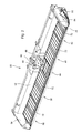
Figure 4 is a perspective view of the frame of the header, the cutter bar and two deflection rollers for the belts. -
Figure 5 shows a side-view of the frame and the rollers in two possible positions. -
Figure 1 illustrates a self-propelledcombine 10 commonly used in a grain farming operation to harvest a variety of crops from a field. An onboard engine (not shown) powers thecombine 10, while ground eng agingwheels 14 support and propel the machine. An operator controls thecombine 10 from an operator's station located in acab 16 at the front of the machine. - A
feederhouse 20 pivotally attaches at the front of thecombine 10, supporting aheader 22 removably attached to the front of thefeed erhouse 20. A pair oflift cylinders 24 support and articulate thefeederhouse 20 from thecombine 10, enabling the raising and lowering of theheader 22 relative to the ground. - During a harvesting operation, th e combine 10 moves forward through the field with the
header 22 lowered to a working height. Theheader 22 cuts and transfers crop material to thefeederhouse 20, which in turn transfers the crop material into thecombine 10. Once inside the combine, thres hing and separatingassemblies 26 remove grain from the non-grain crop material and transfer it to agrain tank 28 for temporary holding. Crop material other than grain exits from the rear of thecombine 10. Anunloading auger 30 transfers the grain from thegrain tank 28 to a truck or grain cart for transport, or to another receiving bin for holding. In the following, all references to directions are quoted with respect to the forward direction ofcombine 10 which extends inFigure 1 to the left side. -
Figure 2 shows a perspective view of theheader 22, which is a draper type header and includes aframe 32 supporting acutter bar 34 extending over the entire width ofheader 22, a first transverseconveyor belt assembly 36, a second transverseconveyor belt assembly 38, a third transverseconveyor belt assembly 40, a fourth transverseconveyor belt assembly 42 and a fifthconveyor belt assembly 44. While during operation, the first and second conveyor belt assemblies 36, 38 convey the crop cut by thecutter bar 34 to the left and thus towards the center ofheader 22, the third and fourth conveyor belt assemblies 40, 42 convey the crop cut by thecutter bar 34 to the right and thus towards the center ofheader 22, where it is fed by the fifthconveyor belt assembly 44 and an uppertransverse drum conveyor 48 with outwardly extending fingers towards a rear exit opening 46 offrame 32 and thus to thefeederhouse 20. Areel assembly 50 shown inFigure 1 is also supported onframe 32 and moves crop standing on the field towards thecutter bar 34. Theframe 32 comprises vertically extendingrear cover sheets 52 mounted behind the conveyor belt assemblies 36 -42, andside walls 54 at both ends. - As can be seen from
Figure 3 , theframe 32 includes a transverse,cylindri cal beam 56 with a circular cross section.Beam 56 extends outward from the center portion of the frame of theheader 22. Therear cover sheets 52 and theside walls 54 are directly mounted tobeam 56, which is supported on thefeederhouse 20 by a supportingassembly 62 supportingbeam 56 on top of the front portion of thefeederhouse 20. Thebeam 56 further supports a number of forwardly extendingsupport frames 58 distributed over the width ofbeam 56. Thesupport frames 58 are pivotally mounted to the be am 56 around thelongitudinal axis 56beam 56 by way ofrings 60 enclosingbeam 56. Therings 60 are mounted to arespective support frame 58, as shown inFigure 4 . By suitable stops (not shown), the angular range that thesupport frames 58 can rotate aroundbeam 56 can be restricted. Thesupport frames 58 carry on their front ends thecutter bar 34 as well as lower groundengaging skids 64 andupper crop guides 66 having a vertical front wall and an upper, horizontal wall extending towards the rear beyond the front edges of the conveyor belt assemblies 36 -42. The right half of theframe 32 ofheader 22 comprises in total eightsupport frames 58. - The
outermost support frame 58 mounts aroller 68, while the two succeedingsupport frames 58mount stabilization rods 70. The next (fourth seen from the right end)support frame 58 mounts tworollers 68, while the three succeedingsupport frames 58 also mountstabilization rods 70. The tworollers 68 of thefourth support frame 58 are connected by way of agearbox 74 to ahydraulic motor 76 driving the tworollers 68. Theinnermost support frame 58 finally bears aroller 68. Theconveyor belt assembly 44 is also supported on theinnermost support frame 58, although it might also be independently mounted tobeam 56. Afirst conveyor belt 72 of thefirst belt assembly 36 runs around theroller 68 mounted to therightmost support frame 58 and around theouter roller 68 mounted to the fourth (seen from the right end of header 22)support frame 58, while aconveyor belt 72 of thesecond belt assembly 38 runs around theother roller 68 of thissupport frame 58 and around theroller 68 of theinnermost support frame 58. Theconveyor belts 72 also enclose thetelescopic stabilization rods 70 mounted on theremaining support frames 58. Theconveyor belts 72 include transverse flights. The left half of the header 22 (not shown inFigures 3 and4 ) is arranged symmetric to its right half. - After all, it is apparent that the
support frames 58 can individually move in a vertical direction around thelongitudinal axis 78 of thebeam 56, dependent on the ground contour. Possible end positions of thesupport frames 58 and of therollers 68 are schematically indicated inFigure 5 . Since bothrollers 68 , around which aconveyor belt 72 runs, can move independently, anassembly 80 for guiding theconveyor belt 72 on therollers 68 is provided, that prevents theconveyor belt 72 from running off therollers 68. Thisassembly 80 for guiding theconveyor belt 72 on therollers 68 includes a recess or groove 82 within therollers 68 and aridge 84 on the inner face of theconveyor belt 72, engaging into thegroove 82. Theassembly 80 for guiding theconveyor belt 72 on therollers 68 is located at about 1/5 of the length of theroller 68 in the vicinity of its rear end. This location has the advantage of being relatively close to therotation axis 78 and thus having only a limited vertical movement range, such that theassemblies 80 of bothrollers 68 supporting oneconveyor belt 72 have a sufficiently small relative movement range, thereby avoiding that theconveyor belt 72 runs off therollers 68, and also providing aflange 86 extending horizontally and forwardly from the lower edge of therear cover sheets 52 and abutting the inner surface of theconveyor belt 72 over a sufficient length to prevent entry of crop and residues into the interior of the belt assemblies 36 -42. Theflanges 86 havecutouts 88 in the area of therollers 68. While they are only indicated schematically inFigure 5 , it c an be seen fromFigure 4 that theflanges 86 extend forward to theridge 84 of theconveyor belt 72, such that theridge 84 abuts avertical end range 90 of theflange 86, preventing entry of crop and residue into the interior of the belt assemblies 36 -42. Since theconveyor belts 72 move relative toaxis 78, while therear cover sheets 52 and theflanges 86 are rigidly mounted to frame 32, theflanges 86 have a convex curved upper surface, allowing a continuous contact with the interior of theconveyor belt 72.
Claims (10)
- A draper platform having a conveyor assembly comprising two rollers and a conveyor belt surrounding both rollers, characterized by an assembly for guiding the conveyor belt on the rollers comprising a ridge and a groove.
- The draper platform described in claim 1 wherein the ridge is provided on an inner surface of the conveyor belt and the groove is an annular groove provided within the roller.
- The draper platform described in claim 2 wherein each of the rollers is mounted to a respective support frame, the support frames independently pivotally mounted to a frame of the platform around a transverse axis at their rear ends, and the assembly provided in the vicinity of the rear end of the rollers.
- The draper platform described in claim 3 wherein the frame supports a horizontally extending flange abutting the inner surface of the conveyor belt.
- The draper platform described in claim 4 wherein the flange extends from a rear cover of the frame to the asse mbly.
- The draper platform described in claim 5 wherein the flange comprises a vertical end range terminating adjacent to the ridge on the conveyor belt.
- A draper platform according to one of the preceding claims, the draper platform comprising a frame, a cutter bar, at least one conveyor assembly comprising two rollers and a conveyor belt surrounding both rollers, each of the rollers mounted to a respective support frame that is independently pivotally mounted to the frame around a transverse axis at its rear end, and an assembly for guiding the conveyor belt on the rollers, the assembly for guiding the conveyor belt on the rollers comprising a ridge on an interior side of the belt and a groove within the roller, the assembly provided in the vicinity of the rear end of the rollers.
- A conveyor belt for use in a draper platform, the conveyor belt arranged to surround two rollers and having a ridge on an interior side, the ridge configured to engage into a first groove in a first roller and int o a second groove of a second roller, both rollers provided on a draper platform that comprises a frame, a cutter bar and the two rollers that are mounted to a respective support frame that is independently pivotally mounted to the frame around a transverse axis at its rear end, the groove provided in the vicinity of the rear end of the roller.
- The conveyor belt described in claim 8 wherein the ridge is provided on an inner surface of the conveyor belt and the groove is an annular groove provided with in the roller.
- The conveyor belt described in claim 9 wherein each of the rollers is mounted to a respective support frame, the support frames independently pivotally mounted to a frame of the platform around a transverse axis at their rear ends, an d the assembly provided in the vicinity of the rear end of the rollers.
Applications Claiming Priority (1)
| Application Number | Priority Date | Filing Date | Title |
|---|---|---|---|
| US12/137,196 US7640720B1 (en) | 2008-06-11 | 2008-06-11 | Draper belt construction to control translation |
Publications (2)
| Publication Number | Publication Date |
|---|---|
| EP2132976A1 true EP2132976A1 (en) | 2009-12-16 |
| EP2132976B1 EP2132976B1 (en) | 2012-02-29 |
Family
ID=41061144
Family Applications (1)
| Application Number | Title | Priority Date | Filing Date |
|---|---|---|---|
| EP09162300A Active EP2132976B1 (en) | 2008-06-11 | 2009-06-09 | Draper belt construction to control translation |
Country Status (9)
| Country | Link |
|---|---|
| US (1) | US7640720B1 (en) |
| EP (1) | EP2132976B1 (en) |
| AR (1) | AR072087A1 (en) |
| AT (1) | ATE546992T1 (en) |
| AU (1) | AU2009201561A1 (en) |
| BR (1) | BRPI0902043B1 (en) |
| CA (1) | CA2666716A1 (en) |
| RU (1) | RU2009120215A (en) |
| UA (1) | UA101146C2 (en) |
Cited By (2)
| Publication number | Priority date | Publication date | Assignee | Title |
|---|---|---|---|---|
| WO2013152990A1 (en) * | 2012-04-11 | 2013-10-17 | Cnh Belgium N.V. | A round baler with a belt assembly and a method for manufacturing a roller for a belt assembly. |
| DE102013204977B4 (en) * | 2012-04-05 | 2021-02-04 | Deere & Company | Cutting unit with cross conveyor belts and conveyor rollers pivotable around the vertical axis |
Families Citing this family (44)
| Publication number | Priority date | Publication date | Assignee | Title |
|---|---|---|---|---|
| US20080271426A1 (en) * | 2006-02-10 | 2008-11-06 | Agco Corporation | Draper belt with crop-retaining rib |
| US20090266044A1 (en) * | 2008-04-25 | 2009-10-29 | Coers Bruce A | Integrated draper belt support and skid shoe in an agricultural harvesting machine |
| US7921627B2 (en) * | 2008-05-09 | 2011-04-12 | Agco Corporation | Interlocking belt guards for a draper header |
| US8402728B2 (en) * | 2010-06-25 | 2013-03-26 | Macdon Industries Ltd. | Guide arrangement for the draper of a combine harvester pick-up |
| US8281561B2 (en) * | 2010-08-17 | 2012-10-09 | Deere & Company | Flexible draper belt drive for an agricultural harvesting machine |
| DE102010037131A1 (en) * | 2010-08-24 | 2012-03-01 | Claas Selbstfahrende Erntemaschinen Gmbh | cutting |
| US8635844B1 (en) | 2011-03-29 | 2014-01-28 | Hbi Branded Apparel Enterprises, Llc | Method for harvesting bast plants |
| US8272198B1 (en) * | 2011-06-06 | 2012-09-25 | Allochis Jose Luis | Flexible platform jointed to a conveyor belt for a combine harvesting, chopping and spinning machine |
| US9258944B2 (en) * | 2011-06-06 | 2016-02-16 | Jose Luis Allochis | Flexible platform joined to a conveyor belt for a combine harvester |
| US8291686B1 (en) * | 2011-06-17 | 2012-10-23 | Macdon Industries Ltd | Draper canvas with a shaped edge |
| US8479483B1 (en) | 2011-12-27 | 2013-07-09 | Agco Corporation | Flexible draper head providing reduced crop residue accumulation |
| EP2797403B1 (en) * | 2011-12-28 | 2016-11-30 | Agco Corporation | Skid plate for crop header having flexible cutterbar |
| US8511050B1 (en) * | 2012-08-31 | 2013-08-20 | Macdon Industries Ltd. | Draper support of a crop harvesting header |
| US8752359B2 (en) * | 2012-08-31 | 2014-06-17 | Macdon Industries Ltd. | Draper support of a crop harvesting header |
| CA2799093A1 (en) * | 2012-12-18 | 2014-06-18 | Honey Bee Manufacturing Ltd. | Draper seal for crop header |
| DE102013100322A1 (en) * | 2013-01-14 | 2014-07-17 | Claas Selbstfahrende Erntemaschinen Gmbh | cutting |
| CN103444365B (en) * | 2013-07-31 | 2016-08-24 | 张武昌 | Radial type feeding delivery chute structure in a kind of united reaper |
| US20150156969A1 (en) * | 2013-12-11 | 2015-06-11 | Deere & Company | Harvesting head |
| US9750190B2 (en) * | 2013-12-11 | 2017-09-05 | Deere & Company | Harvesting head upper belt conveyor compressing crop against a center belt conveyor |
| DE102014009158B4 (en) * | 2014-06-25 | 2023-01-26 | Carl Geringhoff Gmbh & Co. Kg | Cutting unit with support wheels |
| US9861036B2 (en) * | 2014-07-15 | 2018-01-09 | Cnh Industrial America Llc | Skid shoe for a header of an agricultural harvester |
| US10462968B2 (en) * | 2016-11-24 | 2019-11-05 | Macdon Industries Ltd. | Header with flexible crop cutting knife |
| CA3081598C (en) * | 2016-11-24 | 2022-09-06 | Macdon Industries Ltd. | Multi-section header with flexible crop cutting knife |
| US10206332B2 (en) | 2017-04-22 | 2019-02-19 | Deere & Company | Draper belt guide |
| US10182528B2 (en) | 2017-04-22 | 2019-01-22 | Deere & Company | Draper belt assembly |
| US10264728B2 (en) * | 2017-06-16 | 2019-04-23 | Deere & Company | Harvester head draper belt tracking |
| US11589512B2 (en) * | 2017-07-25 | 2023-02-28 | Cnh Industrial America Llc | Draper support for a draper belt assembly of an agricultural harvester |
| US10390486B2 (en) * | 2017-10-11 | 2019-08-27 | Deere & Company | Polymer used as draper belt contact surface |
| US10568265B2 (en) * | 2017-10-31 | 2020-02-25 | Deere & Company | Draper belt roller support |
| GB2569888A (en) * | 2017-11-30 | 2019-07-03 | Primary Sales Australia Pty Ltd | Conveyor assembly for a harvester |
| DE102018107804A1 (en) * | 2018-04-03 | 2019-10-10 | Claas Selbstfahrende Erntemaschinen Gmbh | Height control system for a header |
| US12150409B2 (en) * | 2018-11-16 | 2024-11-26 | Cnh Industrial America Llc | Airbag system for a harvester header |
| WO2020101993A1 (en) * | 2018-11-16 | 2020-05-22 | Cnh Industrial America Llc | Harvester header with lateral belt roller mount |
| USD900886S1 (en) * | 2019-01-15 | 2020-11-03 | Deere & Company | Row unit crop guides |
| DE102019125277A1 (en) * | 2019-09-19 | 2021-03-25 | Carl Geringhoff Gmbh & Co. Kg | Cutting unit with a leaf spring package as a cutting element carrier |
| DE102019125279A1 (en) * | 2019-09-19 | 2021-03-25 | Carl Geringhoff Gmbh & Co. Kg | Cutting unit with longitudinally movable support element to support a conveying surface |
| US11617300B2 (en) * | 2019-12-23 | 2023-04-04 | Cnh Industrial America Llc | Locking mechanism for an agricultural header |
| US11559000B2 (en) * | 2020-05-29 | 2023-01-24 | Deere & Company | Lockout system for header |
| US12396393B2 (en) | 2021-07-20 | 2025-08-26 | Deer & Company | Automated lockout system for header |
| US12402561B2 (en) | 2021-07-20 | 2025-09-02 | Deere & Company | Automated lockout system for header |
| US12396387B2 (en) | 2021-07-20 | 2025-08-26 | Deere & Company | Automated lockout system for header |
| US12575497B2 (en) | 2021-09-08 | 2026-03-17 | Deere & Company | Automated lockout system for header |
| US20240008409A1 (en) * | 2022-07-05 | 2024-01-11 | Cnh Industrial America Llc | Belt support for draper header of agricultural vehicle |
| CN116508497A (en) * | 2023-06-05 | 2023-08-01 | 四川农业大学 | Active conveying device for materials of cutting table of soybean harvester |
Citations (5)
| Publication number | Priority date | Publication date | Assignee | Title |
|---|---|---|---|---|
| US3151429A (en) * | 1961-01-06 | 1964-10-06 | Owatonna Mfg Company Inc | Self-propelled swather |
| US20050022491A1 (en) | 2003-07-10 | 2005-02-03 | Rolf Zurn | Crop gathering device with conveyor belt assembly |
| US20060254241A1 (en) | 2005-05-11 | 2006-11-16 | Gunter Kempf | Combine head with conveyor belt assemblies |
| WO2007095430A2 (en) | 2006-02-10 | 2007-08-23 | Agco Corporation | Combine harvester draper header having flexible cutterbar |
| US20080092508A1 (en) | 2006-10-20 | 2008-04-24 | Talbot Francois R | Crop header with draper canvas and a seal with an element of the cutter bar |
Family Cites Families (13)
| Publication number | Priority date | Publication date | Assignee | Title |
|---|---|---|---|---|
| US3597907A (en) | 1965-02-15 | 1971-08-10 | Love Co J E | Header elevational control system for crop-harvesting machine |
| US3623304A (en) | 1970-03-30 | 1971-11-30 | Int Harvester Co | Hydraulic system for supporting a harvester platform |
| US3717995A (en) | 1971-10-12 | 1973-02-27 | Hesston Corp | Hydraulic flotation for implement header |
| US4622803A (en) | 1984-06-28 | 1986-11-18 | J. I. Case Company | Header flotation |
| US4724661A (en) | 1986-09-04 | 1988-02-16 | New Holland Inc. | Two piece crop harvesting header and flotation mechanism therefor |
| US5471823A (en) | 1994-06-24 | 1995-12-05 | Case Corporation | Electronic combine head float control system |
| US5577373A (en) | 1994-06-24 | 1996-11-26 | Case Corporation | Agricultural vehicle including a system for automatically moving an implement and improved ground height sensing to a predetermined operating position |
| US5822959A (en) * | 1996-05-06 | 1998-10-20 | Norton; R. Scott | Pick-up for harvesting a lying crop |
| US6041583A (en) | 1998-11-16 | 2000-03-28 | Deere & Company | Height sensing system for a harvester head |
| DE10133105A1 (en) * | 2001-07-12 | 2003-02-06 | Claas Selbstfahr Erntemasch | Harvester header |
| CA2369862C (en) | 2002-01-31 | 2009-10-27 | Norbert Beaujot | Header height control apparatus |
| US20080271426A1 (en) * | 2006-02-10 | 2008-11-06 | Agco Corporation | Draper belt with crop-retaining rib |
| US20090266044A1 (en) * | 2008-04-25 | 2009-10-29 | Coers Bruce A | Integrated draper belt support and skid shoe in an agricultural harvesting machine |
-
2008
- 2008-06-11 US US12/137,196 patent/US7640720B1/en active Active
-
2009
- 2009-04-23 AU AU2009201561A patent/AU2009201561A1/en not_active Abandoned
- 2009-04-30 UA UAA200904308A patent/UA101146C2/en unknown
- 2009-05-25 CA CA002666716A patent/CA2666716A1/en not_active Abandoned
- 2009-05-27 RU RU2009120215/21A patent/RU2009120215A/en not_active Application Discontinuation
- 2009-06-09 BR BRPI0902043-8A patent/BRPI0902043B1/en active IP Right Grant
- 2009-06-09 EP EP09162300A patent/EP2132976B1/en active Active
- 2009-06-09 AT AT09162300T patent/ATE546992T1/en active
- 2009-06-10 AR ARP090102090A patent/AR072087A1/en active IP Right Grant
Patent Citations (5)
| Publication number | Priority date | Publication date | Assignee | Title |
|---|---|---|---|---|
| US3151429A (en) * | 1961-01-06 | 1964-10-06 | Owatonna Mfg Company Inc | Self-propelled swather |
| US20050022491A1 (en) | 2003-07-10 | 2005-02-03 | Rolf Zurn | Crop gathering device with conveyor belt assembly |
| US20060254241A1 (en) | 2005-05-11 | 2006-11-16 | Gunter Kempf | Combine head with conveyor belt assemblies |
| WO2007095430A2 (en) | 2006-02-10 | 2007-08-23 | Agco Corporation | Combine harvester draper header having flexible cutterbar |
| US20080092508A1 (en) | 2006-10-20 | 2008-04-24 | Talbot Francois R | Crop header with draper canvas and a seal with an element of the cutter bar |
Cited By (3)
| Publication number | Priority date | Publication date | Assignee | Title |
|---|---|---|---|---|
| DE102013204977B4 (en) * | 2012-04-05 | 2021-02-04 | Deere & Company | Cutting unit with cross conveyor belts and conveyor rollers pivotable around the vertical axis |
| WO2013152990A1 (en) * | 2012-04-11 | 2013-10-17 | Cnh Belgium N.V. | A round baler with a belt assembly and a method for manufacturing a roller for a belt assembly. |
| BE1020606A3 (en) * | 2012-04-11 | 2014-01-07 | Cnh Belgium Nv | ROUND BALL PRESS WITH BELT WHOLE AND METHOD FOR MANUFACTURING A ROLL FOR A BELT WHOLE. |
Also Published As
| Publication number | Publication date |
|---|---|
| BRPI0902043A2 (en) | 2010-04-13 |
| BRPI0902043B1 (en) | 2018-05-29 |
| CA2666716A1 (en) | 2009-12-11 |
| US7640720B1 (en) | 2010-01-05 |
| AR072087A1 (en) | 2010-08-04 |
| US20090308042A1 (en) | 2009-12-17 |
| EP2132976B1 (en) | 2012-02-29 |
| AU2009201561A1 (en) | 2010-01-07 |
| ATE546992T1 (en) | 2012-03-15 |
| UA101146C2 (en) | 2013-03-11 |
| RU2009120215A (en) | 2010-12-10 |
Similar Documents
| Publication | Publication Date | Title |
|---|---|---|
| EP2132976B1 (en) | Draper belt construction to control translation | |
| EP2420128B1 (en) | Flexible draper belt drive for an agricultural harvesting machine | |
| EP3473075B1 (en) | Center feed assembly for a draper | |
| EP1385366B1 (en) | Elevator slats for an agricultural harvesting machine | |
| US7650737B1 (en) | Reel finger for use on a harvesting header for an agricultural machine | |
| CA2455653C (en) | Drive train for a header of a harvesting machine | |
| US8166738B1 (en) | Combine header with crop compression rollers | |
| EP2586284B1 (en) | Pivoting mount for a knife drive | |
| EP3613274A1 (en) | Corn header row unit | |
| US10820515B2 (en) | Combine header with feed assist bulky crop auger on a draper platform | |
| US4083167A (en) | Multi-row crop header | |
| JP6436884B2 (en) | Harvesting machine | |
| EP4346369B1 (en) | Multi-segment header for an agricultural harvester | |
| JP5756364B2 (en) | Normal combine | |
| US4338770A (en) | Row unit for a cotton harvester | |
| US4291523A (en) | Row crop apparatus | |
| JP5996039B2 (en) | Normal combine | |
| JP7610979B2 (en) | Sugarcane harvester | |
| JP2015165816A5 (en) | ||
| JP7266487B2 (en) | harvester | |
| US11412659B2 (en) | Active backsheet for a grain header | |
| JP7325276B2 (en) | sugar cane harvester | |
| JP2022092902A (en) | combine | |
| JP5231945B2 (en) | Combine weed structure | |
| JP2017051165A (en) | Harvesting machine |
Legal Events
| Date | Code | Title | Description |
|---|---|---|---|
| PUAI | Public reference made under article 153(3) epc to a published international application that has entered the european phase |
Free format text: ORIGINAL CODE: 0009012 |
|
| AK | Designated contracting states |
Kind code of ref document: A1 Designated state(s): AT BE BG CH CY CZ DE DK EE ES FI FR GB GR HR HU IE IS IT LI LT LU LV MC MK MT NL NO PL PT RO SE SI SK TR |
|
| 17P | Request for examination filed |
Effective date: 20100616 |
|
| 17Q | First examination report despatched |
Effective date: 20100712 |
|
| GRAP | Despatch of communication of intention to grant a patent |
Free format text: ORIGINAL CODE: EPIDOSNIGR1 |
|
| GRAS | Grant fee paid |
Free format text: ORIGINAL CODE: EPIDOSNIGR3 |
|
| GRAA | (expected) grant |
Free format text: ORIGINAL CODE: 0009210 |
|
| AK | Designated contracting states |
Kind code of ref document: B1 Designated state(s): AT BE BG CH CY CZ DE DK EE ES FI FR GB GR HR HU IE IS IT LI LT LU LV MC MK MT NL NO PL PT RO SE SI SK TR |
|
| REG | Reference to a national code |
Ref country code: GB Ref legal event code: FG4D Ref country code: CH Ref legal event code: EP |
|
| REG | Reference to a national code |
Ref country code: AT Ref legal event code: REF Ref document number: 546992 Country of ref document: AT Kind code of ref document: T Effective date: 20120315 |
|
| REG | Reference to a national code |
Ref country code: IE Ref legal event code: FG4D |
|
| REG | Reference to a national code |
Ref country code: DE Ref legal event code: R096 Ref document number: 602009005588 Country of ref document: DE Effective date: 20120503 |
|
| REG | Reference to a national code |
Ref country code: NL Ref legal event code: VDEP Effective date: 20120229 |
|
| LTIE | Lt: invalidation of european patent or patent extension |
Effective date: 20120229 |
|
| PG25 | Lapsed in a contracting state [announced via postgrant information from national office to epo] |
Ref country code: NO Free format text: LAPSE BECAUSE OF FAILURE TO SUBMIT A TRANSLATION OF THE DESCRIPTION OR TO PAY THE FEE WITHIN THE PRESCRIBED TIME-LIMIT Effective date: 20120529 Ref country code: NL Free format text: LAPSE BECAUSE OF FAILURE TO SUBMIT A TRANSLATION OF THE DESCRIPTION OR TO PAY THE FEE WITHIN THE PRESCRIBED TIME-LIMIT Effective date: 20120229 Ref country code: IS Free format text: LAPSE BECAUSE OF FAILURE TO SUBMIT A TRANSLATION OF THE DESCRIPTION OR TO PAY THE FEE WITHIN THE PRESCRIBED TIME-LIMIT Effective date: 20120629 Ref country code: LT Free format text: LAPSE BECAUSE OF FAILURE TO SUBMIT A TRANSLATION OF THE DESCRIPTION OR TO PAY THE FEE WITHIN THE PRESCRIBED TIME-LIMIT Effective date: 20120229 Ref country code: HR Free format text: LAPSE BECAUSE OF FAILURE TO SUBMIT A TRANSLATION OF THE DESCRIPTION OR TO PAY THE FEE WITHIN THE PRESCRIBED TIME-LIMIT Effective date: 20120229 |
|
| PG25 | Lapsed in a contracting state [announced via postgrant information from national office to epo] |
Ref country code: GR Free format text: LAPSE BECAUSE OF FAILURE TO SUBMIT A TRANSLATION OF THE DESCRIPTION OR TO PAY THE FEE WITHIN THE PRESCRIBED TIME-LIMIT Effective date: 20120530 Ref country code: PT Free format text: LAPSE BECAUSE OF FAILURE TO SUBMIT A TRANSLATION OF THE DESCRIPTION OR TO PAY THE FEE WITHIN THE PRESCRIBED TIME-LIMIT Effective date: 20120629 Ref country code: FI Free format text: LAPSE BECAUSE OF FAILURE TO SUBMIT A TRANSLATION OF THE DESCRIPTION OR TO PAY THE FEE WITHIN THE PRESCRIBED TIME-LIMIT Effective date: 20120229 Ref country code: LV Free format text: LAPSE BECAUSE OF FAILURE TO SUBMIT A TRANSLATION OF THE DESCRIPTION OR TO PAY THE FEE WITHIN THE PRESCRIBED TIME-LIMIT Effective date: 20120229 |
|
| REG | Reference to a national code |
Ref country code: AT Ref legal event code: MK05 Ref document number: 546992 Country of ref document: AT Kind code of ref document: T Effective date: 20120229 |
|
| PG25 | Lapsed in a contracting state [announced via postgrant information from national office to epo] |
Ref country code: CY Free format text: LAPSE BECAUSE OF FAILURE TO SUBMIT A TRANSLATION OF THE DESCRIPTION OR TO PAY THE FEE WITHIN THE PRESCRIBED TIME-LIMIT Effective date: 20120229 |
|
| PG25 | Lapsed in a contracting state [announced via postgrant information from national office to epo] |
Ref country code: RO Free format text: LAPSE BECAUSE OF FAILURE TO SUBMIT A TRANSLATION OF THE DESCRIPTION OR TO PAY THE FEE WITHIN THE PRESCRIBED TIME-LIMIT Effective date: 20120229 Ref country code: SI Free format text: LAPSE BECAUSE OF FAILURE TO SUBMIT A TRANSLATION OF THE DESCRIPTION OR TO PAY THE FEE WITHIN THE PRESCRIBED TIME-LIMIT Effective date: 20120229 Ref country code: EE Free format text: LAPSE BECAUSE OF FAILURE TO SUBMIT A TRANSLATION OF THE DESCRIPTION OR TO PAY THE FEE WITHIN THE PRESCRIBED TIME-LIMIT Effective date: 20120229 Ref country code: PL Free format text: LAPSE BECAUSE OF FAILURE TO SUBMIT A TRANSLATION OF THE DESCRIPTION OR TO PAY THE FEE WITHIN THE PRESCRIBED TIME-LIMIT Effective date: 20120229 Ref country code: CZ Free format text: LAPSE BECAUSE OF FAILURE TO SUBMIT A TRANSLATION OF THE DESCRIPTION OR TO PAY THE FEE WITHIN THE PRESCRIBED TIME-LIMIT Effective date: 20120229 Ref country code: DK Free format text: LAPSE BECAUSE OF FAILURE TO SUBMIT A TRANSLATION OF THE DESCRIPTION OR TO PAY THE FEE WITHIN THE PRESCRIBED TIME-LIMIT Effective date: 20120229 Ref country code: SE Free format text: LAPSE BECAUSE OF FAILURE TO SUBMIT A TRANSLATION OF THE DESCRIPTION OR TO PAY THE FEE WITHIN THE PRESCRIBED TIME-LIMIT Effective date: 20120229 |
|
| PG25 | Lapsed in a contracting state [announced via postgrant information from national office to epo] |
Ref country code: SK Free format text: LAPSE BECAUSE OF FAILURE TO SUBMIT A TRANSLATION OF THE DESCRIPTION OR TO PAY THE FEE WITHIN THE PRESCRIBED TIME-LIMIT Effective date: 20120229 |
|
| PLBE | No opposition filed within time limit |
Free format text: ORIGINAL CODE: 0009261 |
|
| STAA | Information on the status of an ep patent application or granted ep patent |
Free format text: STATUS: NO OPPOSITION FILED WITHIN TIME LIMIT |
|
| PG25 | Lapsed in a contracting state [announced via postgrant information from national office to epo] |
Ref country code: MC Free format text: LAPSE BECAUSE OF NON-PAYMENT OF DUE FEES Effective date: 20120630 Ref country code: AT Free format text: LAPSE BECAUSE OF FAILURE TO SUBMIT A TRANSLATION OF THE DESCRIPTION OR TO PAY THE FEE WITHIN THE PRESCRIBED TIME-LIMIT Effective date: 20120229 |
|
| 26N | No opposition filed |
Effective date: 20121130 |
|
| PG25 | Lapsed in a contracting state [announced via postgrant information from national office to epo] |
Ref country code: MK Free format text: LAPSE BECAUSE OF FAILURE TO SUBMIT A TRANSLATION OF THE DESCRIPTION OR TO PAY THE FEE WITHIN THE PRESCRIBED TIME-LIMIT Effective date: 20120229 |
|
| REG | Reference to a national code |
Ref country code: IE Ref legal event code: MM4A |
|
| REG | Reference to a national code |
Ref country code: DE Ref legal event code: R097 Ref document number: 602009005588 Country of ref document: DE Effective date: 20121130 |
|
| REG | Reference to a national code |
Ref country code: FR Ref legal event code: ST Effective date: 20130228 |
|
| PG25 | Lapsed in a contracting state [announced via postgrant information from national office to epo] |
Ref country code: ES Free format text: LAPSE BECAUSE OF FAILURE TO SUBMIT A TRANSLATION OF THE DESCRIPTION OR TO PAY THE FEE WITHIN THE PRESCRIBED TIME-LIMIT Effective date: 20120609 Ref country code: IE Free format text: LAPSE BECAUSE OF NON-PAYMENT OF DUE FEES Effective date: 20120609 Ref country code: FR Free format text: LAPSE BECAUSE OF NON-PAYMENT OF DUE FEES Effective date: 20120702 |
|
| PG25 | Lapsed in a contracting state [announced via postgrant information from national office to epo] |
Ref country code: MT Free format text: LAPSE BECAUSE OF FAILURE TO SUBMIT A TRANSLATION OF THE DESCRIPTION OR TO PAY THE FEE WITHIN THE PRESCRIBED TIME-LIMIT Effective date: 20120229 Ref country code: BG Free format text: LAPSE BECAUSE OF FAILURE TO SUBMIT A TRANSLATION OF THE DESCRIPTION OR TO PAY THE FEE WITHIN THE PRESCRIBED TIME-LIMIT Effective date: 20120529 |
|
| REG | Reference to a national code |
Ref country code: CH Ref legal event code: PL |
|
| GBPC | Gb: european patent ceased through non-payment of renewal fee |
Effective date: 20130609 |
|
| PG25 | Lapsed in a contracting state [announced via postgrant information from national office to epo] |
Ref country code: TR Free format text: LAPSE BECAUSE OF FAILURE TO SUBMIT A TRANSLATION OF THE DESCRIPTION OR TO PAY THE FEE WITHIN THE PRESCRIBED TIME-LIMIT Effective date: 20120229 Ref country code: CH Free format text: LAPSE BECAUSE OF NON-PAYMENT OF DUE FEES Effective date: 20130630 Ref country code: GB Free format text: LAPSE BECAUSE OF NON-PAYMENT OF DUE FEES Effective date: 20130609 Ref country code: LI Free format text: LAPSE BECAUSE OF NON-PAYMENT OF DUE FEES Effective date: 20130630 |
|
| PG25 | Lapsed in a contracting state [announced via postgrant information from national office to epo] |
Ref country code: LU Free format text: LAPSE BECAUSE OF NON-PAYMENT OF DUE FEES Effective date: 20120609 |
|
| PG25 | Lapsed in a contracting state [announced via postgrant information from national office to epo] |
Ref country code: HU Free format text: LAPSE BECAUSE OF FAILURE TO SUBMIT A TRANSLATION OF THE DESCRIPTION OR TO PAY THE FEE WITHIN THE PRESCRIBED TIME-LIMIT Effective date: 20090609 |
|
| PGFP | Annual fee paid to national office [announced via postgrant information from national office to epo] |
Ref country code: IT Payment date: 20140621 Year of fee payment: 6 |
|
| PG25 | Lapsed in a contracting state [announced via postgrant information from national office to epo] |
Ref country code: IT Free format text: LAPSE BECAUSE OF NON-PAYMENT OF DUE FEES Effective date: 20150609 |
|
| PGFP | Annual fee paid to national office [announced via postgrant information from national office to epo] |
Ref country code: BE Payment date: 20240627 Year of fee payment: 16 |
|
| PGFP | Annual fee paid to national office [announced via postgrant information from national office to epo] |
Ref country code: DE Payment date: 20250521 Year of fee payment: 17 |
|
| REG | Reference to a national code |
Ref country code: BE Ref legal event code: MM Effective date: 20250630 |
|
| PG25 | Lapsed in a contracting state [announced via postgrant information from national office to epo] |
Ref country code: BE Free format text: LAPSE BECAUSE OF NON-PAYMENT OF DUE FEES Effective date: 20250630 |