EP2132078B1 - Door rail and door attachment system for passenger rail cars - Google Patents
Door rail and door attachment system for passenger rail cars Download PDFInfo
- Publication number
- EP2132078B1 EP2132078B1 EP07821940A EP07821940A EP2132078B1 EP 2132078 B1 EP2132078 B1 EP 2132078B1 EP 07821940 A EP07821940 A EP 07821940A EP 07821940 A EP07821940 A EP 07821940A EP 2132078 B1 EP2132078 B1 EP 2132078B1
- Authority
- EP
- European Patent Office
- Prior art keywords
- door
- rail
- guide
- cover
- car
- Prior art date
- Legal status (The legal status is an assumption and is not a legal conclusion. Google has not performed a legal analysis and makes no representation as to the accuracy of the status listed.)
- Active
Links
Images


Classifications
-
- B—PERFORMING OPERATIONS; TRANSPORTING
- B61—RAILWAYS
- B61D—BODY DETAILS OR KINDS OF RAILWAY VEHICLES
- B61D19/00—Door arrangements specially adapted for rail vehicles
- B61D19/003—Door arrangements specially adapted for rail vehicles characterised by the movements of the door
- B61D19/005—Door arrangements specially adapted for rail vehicles characterised by the movements of the door sliding
Definitions
- the invention relates to a door fastening system of a rail vehicle, in particular passenger rail vehicle, and a door guide for a sliding door system of such a rail vehicle with a along a horizontal edge of a door opening of the car body of the rail vehicle extending and attachable to the car body guide carrier, wherein a guide means for slidably receiving carriers of a Sliding door is provided, wherein for covering at least the door guide and the carriers outwardly a cover is provided, said cover is part of the guide carrier and is integrally formed with a guide rail carrier.
- Door mounting systems of this type are well known, for example in connection with subway cars.
- the cover of the door attachment serves as a mechanical protection of the mechanism of the door guide including protection against dust, rain and water spray as well as privacy, but also, conversely, to protect the passengers from injury to the door guide mechanism.
- Door guides according to the prior art are, for example, in WO 02 / 18735A1 disclosed.
- German utility model G 82 26 126U1 an external double sliding door is shown, which has a cover of the door movement mechanism.
- Another solution for protecting the door movement mechanism from environmental influences is in GB 2 071 582 A disclosed.
- FIG. 4 4 shows the part of the car above the door opening (lintel) in a cross-sectional view
- the cover 111 of the upper door guide with guide support 112 is a part of the car body 113.
- the cover 111 forms on the car body a projection which is on the outside upwards and pulled down.
- the pulled-up portion 114 forms a channel that extends over the length of the door, usually along the entire car and has introduced the name "gutter cover" because of their function of the cover 111.
- the pulled-down part of the gutter cover 111 should, for reasons of tightness and acoustics, cover the door leaf 117.
- the cover 111 is additionally provided with a diaphragm 116, which provides a closed impression of the cover to the viewer.
- the lower door guide cover 121 shown is a separate component mounted on the lower car body portion 123 by means of a tab 124 or the like.
- the cover 121 is mounted below the door sill and the associated guide support 122 and protrudes from there the door guide.
- the cover is in the known constructions thus part of the car body assembly. This makes the construction of the cover complex and complicates the (independent) assembly of the door guide and sliding door, since the door guide belongs to the same assembly as the door, which is usually purchased from a separate provider.
- the cover has a fastening means by means of which the cover is additionally attachable to the car body.
- This solution requires an assembly-overlapping design of the guide cover or a reassignment of the cover to the assembly of the door guide, but brings various advantages, such as. simplified assembly and maintenance and shorter assembly times.
- the reduction in the number of components results in addition to the simplification of a cost reduction, and not least improved stability of the cover.
- the cover By integrating the cover into the guide carrier, the consideration of a separate interface on the car body for the cover is unnecessary.
- the guide device has a guide rail for holding elements of the sliding door held displaceably therein, the cover being preferably integrally formed with the guide rail.
- the cover is integrally formed with a permanently connectable to the car body component of the guide carrier to improve the stability of the construction and to avoid sealing joints.
- the guide means adjusting means for adjusting the position of the sliding door it is advantageous if the adjusting means facing the inside of the sliding door and operated from the inside. This facilitates access to these elements during installation and maintenance.
- the cover may advantageously have a fastening means by means of which the cover is additionally attachable to the car body.
- a particularly significant application of the invention relates to exterior sliding doors;
- the management carrier is favorably turned outward.
- a door guide according to the invention for a lintel and a door sill of a door opening are preferably realized in each case in which the guide device is provided for slidably receiving retaining elements on the upper or lower edge of the sliding door.
- FIG Fig. 1 A double sliding door system embodying the invention is shown in FIG Fig. 1 shown.
- the upper cover 11 and the lower cover 12 each obscure the view of (thus hidden) door guide mechanisms that hold the door leaves of the sliding door 13a, 13b and guide and guide the sliding movement.
- the top cover 11 extends over the entire length of the cart (typically about 20 m), partly for aesthetic reasons, partly because of the improved mechanical strength and possibly the function as a "gutter" for draining water, while the bottom cover 12 is realized only in the door area and is interrupted between the door areas.
- the length of the lower cover 12 is chosen so that it covers the entire lower door guide, so that even in the fully open state, the door leaves do not protrude beyond the cover.
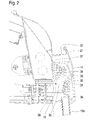
- Fig. 2 shows the upper door guide according to the invention integrated upper cover 11 in a detail of a cross-sectional view on section plane AA Fig. 1 (Approximately on the center of the double door) corresponding to a section showing the environment of the upper door edge on the right side of the car.
- the door guide is used to hold the door and steering the door movement.
- the guide bracket 15 is divided into a guide rail support 30 and a fastening strip 31, by means of which the upper door guide on the car body 17th is fastened, as well as the cover 11, which is connected according to the invention as part of the guide support 15 with the guide rail support 30 and the mounting strip 31 and preferably with these components in one piece.
- a guide rail 32 is mounted on the mounting strip 31 .
- the guide rail 32 serves to guide the door leaves via holding elements, in the form of carriers 33, which are connected via runners 34 with the door leaf, so that the door leaves are slidably mounted.
- the carrier 33 have according to a conventional manner adjusting screws 35, with the aid of which the position of the door can be adjusted.
- the cover 11 according to the invention is integrated with the guide rail 32, the adjusting screws 35 are now moved towards the upper edge of the door and turned toward the car interior to allow the user access from the inside. This is in contrast to known constructions (cf. Fig. 5 ), where the adjustment 118 arranged in the immediate vicinity of the guide rail and - after removing the cover 111 - are operated from the outside.
- the adjusting means for adjusting the position of the door can be realized by the guide carrier.
- the cover 11 covers the guide rail 32, the carrier 33 including the runners 34 and the upper edge of the door leaf. At its upper outer edge, the cover 11 preferably has a projection 21 which is directed like a sheet upwards and mounted in a corresponding projection 22 of the car body 17, eg hung.
- the projection 22 can realize, for example, a "gutter”.
- seals 36, 37 (relative to the door leaf or the car body 17) ensure the sealing of the mechanics and the passenger compartment against contamination from the outside. In addition, this results in that the cover 11 extends over the entire length of the carriage - especially if it is integral with the guide support 15 - an increased mechanical stability and improved overall aesthetic impression of the car.
- Fig. 3 shows in another detail (analogous to the Fig. 2
- the lower door guide is realized with a guide bracket 16 having a guide rail support (body) 41 which is fixedly connected to the car body 17.
- the cover 12 is according to the invention part of the guide support 16; Preferably, it is integrally formed with the guide rail carrier 41.
- the cover 12 may be additionally fastened with a further fastening means 44 on the side surface of the car body 17.
- the fasteners used here are, for example, threaded bolts, which are guided and screwed through a hole or slot hole; Of course, other suitable means are also possible.
- a lower guide rail 42 is screwed in the case shown as a separate component on the guide rail carrier 41.
- the component of the guide rail 31 with integrated upper cover 11 can be made as an aluminum extruded profile, as well as the guide rail support 41 with integrated lower cover 12.
- terminal bores 43 are carried out to which end caps can be attached.
- the lower cover 12 is used in addition to their function as splash water and privacy protection as bridging the gap to the platform (step assistance).
- the integral realization with the guide support 16 results in a significantly increased stability and improved effect as splash protection.
Abstract
Description
Die Erfindung betrifft ein Türbefestigungssystem eines Schienenfahrzeugs, insbesondere Passagierschienenfahrzeugs, sowie eine Türführung für ein Schiebetürsystem eines solchen Schienenfahrzeugs mit einem entlang eines horizontalen Randes einer Türöffnung des Wagenkastens des Schienenfahrzeugs verlaufenden und an dem Wagenkasten befestigbaren Führungsträger, bei dem eine Führungseinrichtung zur verschieblichen Aufnahme von Trägern einer Schiebetür vorgesehen ist, wobei zum Abdecken von zumindest der Türführung und den Trägern nach außen eine Abdeckung vorgesehen ist, wobei diese Abdeckung Teil des Führungsträgers ist und mit einem Führungsschienenträger einstückig ausgebildet ist.The invention relates to a door fastening system of a rail vehicle, in particular passenger rail vehicle, and a door guide for a sliding door system of such a rail vehicle with a along a horizontal edge of a door opening of the car body of the rail vehicle extending and attachable to the car body guide carrier, wherein a guide means for slidably receiving carriers of a Sliding door is provided, wherein for covering at least the door guide and the carriers outwardly a cover is provided, said cover is part of the guide carrier and is integrally formed with a guide rail carrier.
Türbefestigungssysteme dieser Art sind wohlbekannt, beispielsweise in Zusammenhang mit U-Bahn-Wagen. Die Abdeckung der Türbefestigung dient als mechanischer Schutz der Mechanik der Türführung einschließlich dem Schutz vor Staub, Regen und Spritzwasser sowie als Sichtschutz, aber auch, umgekehrt, dem Schutz der Fahrgäste vor Verletzungen an der Türführungsmechanik. Türführungen gemäß dem Stand der Technik sind beispielsweise in
Ein typisches Beispiel einer bekannten Realisierung einer Türbefestigung mit Abdeckung bei dem Türsturz und der Türschwelle eines U-Bahn-Wagens ist jeweils in
Die in
Die Abdeckung ist in den bekannten Konstruktionen somit ein Teil der Wagenkastenbaugruppe. Dies macht die Konstruktion der Abdeckung aufwändig und verkompliziert die (unabhängige) Montage der Türführung und Schiebetür, da die Türführung zu derselben Baugruppe gehört wie die Tür, die zumeist von einem getrennten Anbieter zugekauft wird.The cover is in the known constructions thus part of the car body assembly. This makes the construction of the cover complex and complicates the (independent) assembly of the door guide and sliding door, since the door guide belongs to the same assembly as the door, which is usually purchased from a separate provider.
Es ist daher Aufgabe der Erfindung, einen Weg zu finden, der die genannten Nachteile überwindet und die Konstruktion und Montage von Türführung und Abdeckung vereinfacht.It is therefore an object of the invention to find a way that overcomes the disadvantages mentioned and simplifies the design and installation of door guide and cover.
Die gestellte Aufgabe wird von einer Türführung gelöst, bei welcher gemäß der Erfindung die Abdeckung ein Befestigungsmittel aufweist, mittels dessen die Abdeckung zusätzlich an dem Wagenkasten befestigbar ist.The stated object is achieved by a door guide, wherein according to the invention, the cover has a fastening means by means of which the cover is additionally attachable to the car body.
Diese Lösung erfordert eine Baugruppen-übergreifende Gestaltung der Führungsabdeckung bzw. eine Neuzuordnung der Abdeckung zur Baugruppe der Türführung, bringt jedoch verschiedene Vorteile, wie z.B. vereinfachte Montage und Wartung und verkürzte Montagezeiten. Die Verringerung der Zahl der Bauteile ergibt neben der Vereinfachung auch eine Kostenreduktion, sowie nicht zuletzt eine verbesserte Stabilität der Abdeckung. Durch die Integration der Abdeckung in den Führungsträger erübrigt sich die Berücksichtigung einer eigenen Schnittstelle am Wagenkasten für die Abdeckung.This solution requires an assembly-overlapping design of the guide cover or a reassignment of the cover to the assembly of the door guide, but brings various advantages, such as. simplified assembly and maintenance and shorter assembly times. The reduction in the number of components results in addition to the simplification of a cost reduction, and not least improved stability of the cover. By integrating the cover into the guide carrier, the consideration of a separate interface on the car body for the cover is unnecessary.
In einer bevorzugten Ausführungsform der Erfindung weist die Führungseinrichtung eine Führungsschiene für darin verschieblich gehaltene Halteelemente der Schiebetür auf, wobei die Abdeckung mit der Führungsschiene vorzugsweise einstückig ausgebildet ist.In a preferred embodiment of the invention, the guide device has a guide rail for holding elements of the sliding door held displaceably therein, the cover being preferably integrally formed with the guide rail.
Vorzugsweise ist die Abdeckung mit einer am Wagenkasten fest verbindbaren Komponente des Führungsträgers einstückig ausgebildet, um die Stabilität der Konstruktion zu verbessern und Dichtfugen zu vermeiden.Preferably, the cover is integrally formed with a permanently connectable to the car body component of the guide carrier to improve the stability of the construction and to avoid sealing joints.
Im Hinblick auf seitens der Führungseinrichtung vorgesehene Einstellmittel zum Einstellen der Position der Schiebetür ist es vorteilhaft, wenn die Einstellmittel der Innenseite der Schiebetüre zugewandt und von innen bedienbar sind. Dies erleichtert den Zugang zu diesen Elementen bei Montage und Wartung.With regard to provided by the guide means adjusting means for adjusting the position of the sliding door, it is advantageous if the adjusting means facing the inside of the sliding door and operated from the inside. This facilitates access to these elements during installation and maintenance.
Die Abdeckung kann vorteilhafter Weise ein Befestigungsmittel aufweisen, mittels dessen die Abdeckung zusätzlich an dem Wagenkasten befestigbar ist.The cover may advantageously have a fastening means by means of which the cover is additionally attachable to the car body.
Weiters verbessert es die Schutzwirkung der Führungsabdeckung (Schutz der Mechanik, Verletzungsschutz, Schutz vor Spritz-und Regenwasser usf.), wenn sie auch einen Randstreifen der Schiebetür überragt.Furthermore, it improves the protective effect of the guide cover (protection of the mechanism, protection against injury, protection against spray and rainwater, etc.), even if it also projects beyond an edge strip of the sliding door.
Eine besonders bedeutsame Anwendung der Erfindung betrifft Außenschiebetüren; in diesem Fall ist der Führungsträger günstiger Weise nach außen gewandt.A particularly significant application of the invention relates to exterior sliding doors; In this case, the management carrier is favorably turned outward.
In einem Türbefestigungssystem eines Schienenfahrzeugs, insbesondere Passagierschienenfahrzeug, sind vorzugsweise je eine erfindungsgemäße Türführung für einen Türsturz und eine Türschwelle einer Türöffnung realisiert, bei denen die Führungseinrichtung zur verschieblichen Aufnahme von Halteelementen am oberen bzw. unteren Rand der Schiebetür vorgesehen ist.In a door fastening system of a rail vehicle, in particular passenger rail vehicle, a door guide according to the invention for a lintel and a door sill of a door opening are preferably realized in each case in which the guide device is provided for slidably receiving retaining elements on the upper or lower edge of the sliding door.
Die Erfindung samt weiteren Vorzügen wird im Folgenden anhand eines nicht einschränkenden Ausführungsbeispiels näher erläutert, das in den beigefügten Zeichnungen dargestellt ist und die Türbefestigung bei einem U-Bahn-Wagen betrifft. Die Zeichnungen zeigen:
- Fig. 1
- einen Türbereich eines U-Bahn-Wagens, in dem die Erfindung realisiert werden kann, in einer Ansicht auf den Wagen von der Seite;
- Fig. 2 und 3
- eine erfindungsgemäße Türbefestigung in Schnittansicht auf die Schnittebene A-A der
Fig. 1 quer zur Längsrichtung des Wagens, wobeiFig. 2 die obere Türführung undFig. 3 die untere Türführung zeigt; sowie - Fig. 4
- und 5 eine bekannten Türbefestigung, wobei die Ansichten denen der
Fig. 2 und3 entsprechen.
- Fig. 1
- a door area of a subway car in which the invention can be realized in a view of the car from the side;
- FIGS. 2 and 3
- a door attachment according to the invention in a sectional view on the sectional plane AA of
Fig. 1 transverse to the longitudinal direction of the car, whereinFig. 2 the upper door guide andFig. 3 the lower door guide shows; such as - Fig. 4
- and Fig. 5 shows a known door attachment, the views being the same as those of Figs
Fig. 2 and3 correspond.
Ein Doppelschiebetürensystem, bei dem die Erfindung realisiert ist, ist in
Auf dem Befestigungsstreifen 31 ist eine Führungsschiene 32 montiert. Die Führungsschiene 32 dient der Führung der Türblätter über Halteelemente, in Form von Trägern 33, die über Läufer 34 mit dem Türblatt verbunden sind, sodass die Türblätter verschieblich befestigt sind. Die Träger 33 weisen nach an sich bekannter Art Einstellschrauben 35 auf, mit deren Hilfe die Position der Türe justiert werden kann. Jedoch sind die Einstellschrauben 35 nun, da die Abdeckung 11 gemäß der Erfindung mit der Führungsschiene 32 integriert ist, zum oberen Rand der Türe hin gerückt und zum Wageninneren hin gewandt, um dem Benutzer den Zugang von innen zu ermöglichen. Dies steht im Gegensatz zu bekannten Konstruktionen (vgl.
Die Abdeckung 11 deckt die Führungsschiene 32, die Träger 33 einschließlich der Läufer 34 und den Oberrand des Türblatts ab. An ihrer oberen Außenkante weist die Abdeckung 11 vorzugsweise einen Vorsprung 21 auf, der blattartig nach oben gerichtet ist und in einem korrespondierenden Vorsprung 22 des Wagenkastens 17 gelagert, z.B. eingehängt. Der Vorsprung 22 kann z.B. eine "Regenrinne" realisieren. In der Abdeckung 11 vorgesehene Dichtungen 36, 37 (gegenüber dem Türblatt bzw. dem Wagenkasten 17) sorgen für die Abdichtung der Mechanik und des Fahrgastraumes gegenüber Verschmutzungen von außen. Außerdem ergibt sich dadurch, dass sich die Abdeckung 11 über die gesamte Länge des Wagens erstreckt - besonders wenn sie einstückig mit dem Führungsträger 15 ist -, eine erhöhte mechanische Stabilität und eine verbesserte ästhetischer Gesamteindruck des Wagens.The
Eine untere Führungsschiene 42 ist im gezeigten Fall als eigenes Bauteil am Führungsschienenträger 41 aufgeschraubt.A
Der Bauteil der Führungsschiene 31 mit integrierter oberer Abdeckung 11 kann als Aluminiumstrangpressprofil hergestellt sein, ebenso der Führungsschienenträger 41 mit integrierter unterer Abdeckung 12. Am Ende der Profile der Abdeckung 11, 12 können, wie in
Die untere Abdeckung 12 dient neben ihrer Funktion als Spritzwasser- und Sichtschutz auch als Überbrückung des Spaltes zum Bahnsteig (Tritthilfe). Durch die einstückige Realisierung mit dem Führungsträger 16 ergibt sich eine wesentlich erhöhte Stabilität sowie verbesserte Wirkung als Spritzwasserschutz.The
- 1111
- obere Abdeckungtop cover
- 1212
- untere Abdeckunglower cover
- 13a,b13a, b
- Schiebetürensliding doors
- 1515
- oberer FührungsträperUpper leadership body
- 1616
- unterer Führungsträperlower leadership body
- 1717
- Wagenkastencar body
- 2121
- oberer Vorsprung der Abdeckungupper projection of the cover
- 2222
- korr. Vorsprung des Wagenkastenscorr. Advantage of the car body
- 3030
- oberer FührungsschienenträgerUpper guide rail support
- 3131
- Befestigungsstreifenfastener strips
- 3232
- Führungsschieneguide rail
- 3333
- Träger (f. Tür)Carrier (for door)
- 3434
- Gleitstückesliders
- 3535
- Einstellschraubenadjustment
- 36, 3736, 37
- Dichtungenseals
- 4141
- unterer Führungsschienenträgerlower guide rail support
- 4242
- Führungsschieneguide rail
- 4343
- Bohrungen (endständig)Drilling (terminal)
- 4444
- Befestigungattachment
- 111111
- obere Abdeckung (Stand der Technik)top cover (prior art)
- 112112
- obere Türführungupper door guide
- 113113
- Wagenkasten (oberer Bereich)Car body (upper area)
- 114114
- Abdeckung - RegenrinneCover - gutter
- 115115
- Abdeckung ieSCover ie
- 116116
- Abdeckung - BlendeCover - Aperture
- 117117
- Türedoor
- 118118
- Einstellelementeadjustment
- 121121
- untere Abdeckung (Stand der Technik)lower cover (prior art)
- 122122
- untere Türführunglower door guide
- 123123
- Wagenkasten (unterer Bereich)Car body (lower area)
- 124124
- Lascheflap
Claims (9)
- Door rail for a sliding door system of a rail car, in particular a passenger rail car, with a guide carrier (15, 16) which runs along a horizontal edge of a door opening of the car body (17) of the rail car and which can be attached to the car body (17), wherein a guide device (31, 42) for movably accommodating carriers (33) of a sliding door (13a, 13b) is provided, wherein a covering (11, 12) is provided to cover at least the door rail and the carriers (33) outwards, wherein said covering (11, 12) is part of the guide carrier (15, 16) and is designed in one piece with a guide rail carrier (30, 41),
characterised in that
the covering (11, 12) has an attachment device (21, 44), by means of which the covering (11, 12) can additionally be attached to the car body (17). - Door rail according to claim 1,
characterised in that the guide rail carrier (30, 41) is designed to hold a guide rail (32, 42) for carriers (33), movably held therein, of the sliding door (13a, 13b). - Door rail according to one of claims 1 or 2,
characterised in that the covering (11, 12) is designed in one piece with a component (30, 41) of the guide carrier (15, 16) that can be permanently connected to the car body (17). - Door rail according to one of claims 1 to 3,
characterised in that adjusting screws (35) for adjusting the position of the sliding door (13a, 13b) are provided on the guide device, wherein the adjusting means face towards the interior of the sliding door (13a, 13b) and can be operated from inside. - Door rail according to one of claims 1 to 4,
characterised in that the covering (11, 12) also overlaps an edge strip of the sliding door (13a, 13b). - Door rail according to one of claims 1 to 5,
characterised in that the guide carrier (15, 16) is turned outwards for an external sliding door. - Door rail according to one of claims 1 to 6 for the lintel of a door opening, wherein the guide rail (32) is provided for movably accommodating carriers (33) at the top edge of the sliding door (13a, 13b).
- Door rail according to one of claims 1 to 6 for the door sill of a door opening, wherein the guide rail (42) is provided for movably accommodating retaining elements at the bottom edge of the sliding door (13a, 13b).
- Door attachment system of a rail car, in particular a passenger rail car, with a door rail in each case according to claim 7 and 8.
Applications Claiming Priority (2)
| Application Number | Priority Date | Filing Date | Title |
|---|---|---|---|
| ATA540/2007A AT505101A3 (en) | 2007-04-05 | 2007-04-05 | DOOR GUIDE AND DOOR MOUNTING SYSTEM FOR PASSENGER RAIL VEHICLES |
| PCT/EP2007/061580 WO2008122318A1 (en) | 2007-04-05 | 2007-10-29 | Door rail and door attachment system for passenger rail cars |
Publications (2)
| Publication Number | Publication Date |
|---|---|
| EP2132078A1 EP2132078A1 (en) | 2009-12-16 |
| EP2132078B1 true EP2132078B1 (en) | 2012-06-27 |
Family
ID=38996634
Family Applications (1)
| Application Number | Title | Priority Date | Filing Date |
|---|---|---|---|
| EP07821940A Active EP2132078B1 (en) | 2007-04-05 | 2007-10-29 | Door rail and door attachment system for passenger rail cars |
Country Status (5)
| Country | Link |
|---|---|
| US (1) | US8434195B2 (en) |
| EP (1) | EP2132078B1 (en) |
| AT (1) | AT505101A3 (en) |
| ES (1) | ES2386826T3 (en) |
| WO (1) | WO2008122318A1 (en) |
Families Citing this family (3)
| Publication number | Priority date | Publication date | Assignee | Title |
|---|---|---|---|---|
| DE102012203200A1 (en) * | 2012-03-01 | 2013-09-05 | Siemens Aktiengesellschaft | Sliding door of a rail vehicle |
| CN106314465A (en) * | 2016-08-25 | 2017-01-11 | 中车南京浦镇车辆有限公司 | Novel side-vertical integrated installation mechanism of sliding-plug door |
| AT519502B1 (en) * | 2016-12-21 | 2018-09-15 | Siemens Ag Oesterreich | Threshold for a vehicle |
Family Cites Families (7)
| Publication number | Priority date | Publication date | Assignee | Title |
|---|---|---|---|---|
| US1548125A (en) * | 1919-05-03 | 1925-08-04 | Camel Co | Safety top guide for car doors |
| US1768060A (en) * | 1925-08-06 | 1930-06-24 | Camel Co | Door |
| US1798180A (en) * | 1928-02-16 | 1931-03-31 | Camel Co | Car-door track |
| GB2071582B (en) * | 1980-01-31 | 1984-12-05 | Trende Transport Design Ltd | Curtain-sided vehicle bodies |
| DE8226126U1 (en) * | 1982-09-16 | 1982-11-18 | Kiekert GmbH & Co KG, 5628 Heiligenhaus | OUTDOOR DOUBLE SLIDING DOORS FOR VEHICLES |
| AT410819B (en) * | 2000-08-31 | 2003-08-25 | Siemens Sgp Verkehrstech Gmbh | DOOR MOUNTING |
| TW200801513A (en) | 2006-06-29 | 2008-01-01 | Fermiscan Australia Pty Ltd | Improved process |
-
2007
- 2007-04-05 AT ATA540/2007A patent/AT505101A3/en not_active Application Discontinuation
- 2007-10-29 ES ES07821940T patent/ES2386826T3/en active Active
- 2007-10-29 WO PCT/EP2007/061580 patent/WO2008122318A1/en active Application Filing
- 2007-10-29 EP EP07821940A patent/EP2132078B1/en active Active
- 2007-10-29 US US12/594,646 patent/US8434195B2/en active Active
Also Published As
| Publication number | Publication date |
|---|---|
| AT505101A2 (en) | 2008-10-15 |
| EP2132078A1 (en) | 2009-12-16 |
| US8434195B2 (en) | 2013-05-07 |
| WO2008122318A1 (en) | 2008-10-16 |
| ES2386826T3 (en) | 2012-08-31 |
| US20100037434A1 (en) | 2010-02-18 |
| AT505101A3 (en) | 2017-08-15 |
Similar Documents
| Publication | Publication Date | Title |
|---|---|---|
| DE102016200475B3 (en) | Vehicle door assembly with insertion areas on frame-side guide elements for a flush-mounted window concept and assembly method | |
| DE19914427C2 (en) | Motor vehicle roof | |
| DE102007032651A1 (en) | Motor vehicle door | |
| DE102012208670A1 (en) | Vehicle door has door inner skin and door outer skin connected with door inner skin, where door outer skin and door inner skin borders door interior for incorporation of functional components | |
| DE3733229C2 (en) | Vehicle window with a sliding double pane, especially for car doors | |
| EP2132078B1 (en) | Door rail and door attachment system for passenger rail cars | |
| DE2403739A1 (en) | ROOF FOR A MOTOR VEHICLE | |
| DE102005022582A1 (en) | Cover strip and sealing arrangement | |
| DE102014013772B4 (en) | Vehicle with a vehicle door | |
| DE102019213427A1 (en) | Window guide for a window pane of a motor vehicle | |
| DE19848633B4 (en) | Motor vehicle door with self-supporting interior trim | |
| AT405921B (en) | TELESCOPE FOR SWIVELING AND SLIDING DOORS OF VEHICLES | |
| EP0938993B1 (en) | Vehicle roof | |
| DE2037555B2 (en) | Design and arrangement of a rearview mirror for side doors of motor vehicles | |
| DE10135406B4 (en) | Vehicle roof with a roof opening | |
| DE202007008782U1 (en) | Single or multi-wing passenger door for a public transport vehicle | |
| DE102006006126A1 (en) | B-pillar segment for a convertible vehicle | |
| EP3038876B1 (en) | Wagon body for a rail vehicle, having a display device readable from the outside | |
| DE3921381C2 (en) | Door seal assembly for a motor vehicle | |
| DE10220947B4 (en) | Sun protection roller blind for motor vehicle windows | |
| EP3303033B1 (en) | Shading device for a pane or a glass roof region of a vehicle interior | |
| DE102018220840B4 (en) | Motor vehicle body with a pane arrangement | |
| DE102013203873B4 (en) | side rail | |
| DE102013004587B4 (en) | Roof structure for a vehicle body | |
| DE102017124228B4 (en) | Vehicle side structure and motor vehicle |
Legal Events
| Date | Code | Title | Description |
|---|---|---|---|
| PUAI | Public reference made under article 153(3) epc to a published international application that has entered the european phase |
Free format text: ORIGINAL CODE: 0009012 |
|
| 17P | Request for examination filed |
Effective date: 20090723 |
|
| AK | Designated contracting states |
Kind code of ref document: A1 Designated state(s): AT BE BG CH CY CZ DE DK EE ES FI FR GB GR HU IE IS IT LI LT LU LV MC MT NL PL PT RO SE SI SK TR |
|
| RAP1 | Party data changed (applicant data changed or rights of an application transferred) |
Owner name: SIEMENS AG OESTERREICH |
|
| DAX | Request for extension of the european patent (deleted) | ||
| 17Q | First examination report despatched |
Effective date: 20101110 |
|
| GRAP | Despatch of communication of intention to grant a patent |
Free format text: ORIGINAL CODE: EPIDOSNIGR1 |
|
| GRAS | Grant fee paid |
Free format text: ORIGINAL CODE: EPIDOSNIGR3 |
|
| GRAA | (expected) grant |
Free format text: ORIGINAL CODE: 0009210 |
|
| AK | Designated contracting states |
Kind code of ref document: B1 Designated state(s): AT BE BG CH CY CZ DE DK EE ES FI FR GB GR HU IE IS IT LI LT LU LV MC MT NL PL PT RO SE SI SK TR |
|
| REG | Reference to a national code |
Ref country code: GB Ref legal event code: FG4D Free format text: NOT ENGLISH |
|
| REG | Reference to a national code |
Ref country code: CH Ref legal event code: EP |
|
| REG | Reference to a national code |
Ref country code: AT Ref legal event code: REF Ref document number: 564015 Country of ref document: AT Kind code of ref document: T Effective date: 20120715 |
|
| REG | Reference to a national code |
Ref country code: IE Ref legal event code: FG4D Free format text: LANGUAGE OF EP DOCUMENT: GERMAN |
|
| REG | Reference to a national code |
Ref country code: DE Ref legal event code: R096 Ref document number: 502007010140 Country of ref document: DE Effective date: 20120823 |
|
| REG | Reference to a national code |
Ref country code: ES Ref legal event code: FG2A Ref document number: 2386826 Country of ref document: ES Kind code of ref document: T3 Effective date: 20120831 |
|
| REG | Reference to a national code |
Ref country code: GR Ref legal event code: EP Ref document number: 20120401898 Country of ref document: GR Effective date: 20120920 |
|
| PG25 | Lapsed in a contracting state [announced via postgrant information from national office to epo] |
Ref country code: LT Free format text: LAPSE BECAUSE OF FAILURE TO SUBMIT A TRANSLATION OF THE DESCRIPTION OR TO PAY THE FEE WITHIN THE PRESCRIBED TIME-LIMIT Effective date: 20120627 Ref country code: FI Free format text: LAPSE BECAUSE OF FAILURE TO SUBMIT A TRANSLATION OF THE DESCRIPTION OR TO PAY THE FEE WITHIN THE PRESCRIBED TIME-LIMIT Effective date: 20120627 Ref country code: SE Free format text: LAPSE BECAUSE OF FAILURE TO SUBMIT A TRANSLATION OF THE DESCRIPTION OR TO PAY THE FEE WITHIN THE PRESCRIBED TIME-LIMIT Effective date: 20120627 |
|
| REG | Reference to a national code |
Ref country code: NL Ref legal event code: VDEP Effective date: 20120627 |
|
| REG | Reference to a national code |
Ref country code: LT Ref legal event code: MG4D Effective date: 20120627 |
|
| PG25 | Lapsed in a contracting state [announced via postgrant information from national office to epo] |
Ref country code: SI Free format text: LAPSE BECAUSE OF FAILURE TO SUBMIT A TRANSLATION OF THE DESCRIPTION OR TO PAY THE FEE WITHIN THE PRESCRIBED TIME-LIMIT Effective date: 20120627 Ref country code: LV Free format text: LAPSE BECAUSE OF FAILURE TO SUBMIT A TRANSLATION OF THE DESCRIPTION OR TO PAY THE FEE WITHIN THE PRESCRIBED TIME-LIMIT Effective date: 20120627 |
|
| PG25 | Lapsed in a contracting state [announced via postgrant information from national office to epo] |
Ref country code: EE Free format text: LAPSE BECAUSE OF FAILURE TO SUBMIT A TRANSLATION OF THE DESCRIPTION OR TO PAY THE FEE WITHIN THE PRESCRIBED TIME-LIMIT Effective date: 20120627 Ref country code: RO Free format text: LAPSE BECAUSE OF FAILURE TO SUBMIT A TRANSLATION OF THE DESCRIPTION OR TO PAY THE FEE WITHIN THE PRESCRIBED TIME-LIMIT Effective date: 20120627 Ref country code: CY Free format text: LAPSE BECAUSE OF FAILURE TO SUBMIT A TRANSLATION OF THE DESCRIPTION OR TO PAY THE FEE WITHIN THE PRESCRIBED TIME-LIMIT Effective date: 20120627 Ref country code: CZ Free format text: LAPSE BECAUSE OF FAILURE TO SUBMIT A TRANSLATION OF THE DESCRIPTION OR TO PAY THE FEE WITHIN THE PRESCRIBED TIME-LIMIT Effective date: 20120627 Ref country code: IS Free format text: LAPSE BECAUSE OF FAILURE TO SUBMIT A TRANSLATION OF THE DESCRIPTION OR TO PAY THE FEE WITHIN THE PRESCRIBED TIME-LIMIT Effective date: 20121027 Ref country code: SK Free format text: LAPSE BECAUSE OF FAILURE TO SUBMIT A TRANSLATION OF THE DESCRIPTION OR TO PAY THE FEE WITHIN THE PRESCRIBED TIME-LIMIT Effective date: 20120627 |
|
| PG25 | Lapsed in a contracting state [announced via postgrant information from national office to epo] |
Ref country code: PT Free format text: LAPSE BECAUSE OF FAILURE TO SUBMIT A TRANSLATION OF THE DESCRIPTION OR TO PAY THE FEE WITHIN THE PRESCRIBED TIME-LIMIT Effective date: 20121029 Ref country code: PL Free format text: LAPSE BECAUSE OF FAILURE TO SUBMIT A TRANSLATION OF THE DESCRIPTION OR TO PAY THE FEE WITHIN THE PRESCRIBED TIME-LIMIT Effective date: 20120627 |
|
| REG | Reference to a national code |
Ref country code: HU Ref legal event code: AG4A Ref document number: E015125 Country of ref document: HU |
|
| PG25 | Lapsed in a contracting state [announced via postgrant information from national office to epo] |
Ref country code: NL Free format text: LAPSE BECAUSE OF FAILURE TO SUBMIT A TRANSLATION OF THE DESCRIPTION OR TO PAY THE FEE WITHIN THE PRESCRIBED TIME-LIMIT Effective date: 20120627 |
|
| BERE | Be: lapsed |
Owner name: SIEMENS AG OSTERREICH Effective date: 20121031 |
|
| PG25 | Lapsed in a contracting state [announced via postgrant information from national office to epo] |
Ref country code: DK Free format text: LAPSE BECAUSE OF FAILURE TO SUBMIT A TRANSLATION OF THE DESCRIPTION OR TO PAY THE FEE WITHIN THE PRESCRIBED TIME-LIMIT Effective date: 20120627 |
|
| PLBE | No opposition filed within time limit |
Free format text: ORIGINAL CODE: 0009261 |
|
| STAA | Information on the status of an ep patent application or granted ep patent |
Free format text: STATUS: NO OPPOSITION FILED WITHIN TIME LIMIT |
|
| PG25 | Lapsed in a contracting state [announced via postgrant information from national office to epo] |
Ref country code: MC Free format text: LAPSE BECAUSE OF NON-PAYMENT OF DUE FEES Effective date: 20121031 |
|
| REG | Reference to a national code |
Ref country code: CH Ref legal event code: PL |
|
| 26N | No opposition filed |
Effective date: 20130328 |
|
| REG | Reference to a national code |
Ref country code: DE Ref legal event code: R097 Ref document number: 502007010140 Country of ref document: DE Effective date: 20130328 |
|
| PG25 | Lapsed in a contracting state [announced via postgrant information from national office to epo] |
Ref country code: CH Free format text: LAPSE BECAUSE OF NON-PAYMENT OF DUE FEES Effective date: 20121031 Ref country code: BE Free format text: LAPSE BECAUSE OF NON-PAYMENT OF DUE FEES Effective date: 20121031 Ref country code: LI Free format text: LAPSE BECAUSE OF NON-PAYMENT OF DUE FEES Effective date: 20121031 Ref country code: BG Free format text: LAPSE BECAUSE OF FAILURE TO SUBMIT A TRANSLATION OF THE DESCRIPTION OR TO PAY THE FEE WITHIN THE PRESCRIBED TIME-LIMIT Effective date: 20120927 |
|
| REG | Reference to a national code |
Ref country code: IE Ref legal event code: MM4A |
|
| PG25 | Lapsed in a contracting state [announced via postgrant information from national office to epo] |
Ref country code: IE Free format text: LAPSE BECAUSE OF NON-PAYMENT OF DUE FEES Effective date: 20121029 |
|
| PG25 | Lapsed in a contracting state [announced via postgrant information from national office to epo] |
Ref country code: MT Free format text: LAPSE BECAUSE OF FAILURE TO SUBMIT A TRANSLATION OF THE DESCRIPTION OR TO PAY THE FEE WITHIN THE PRESCRIBED TIME-LIMIT Effective date: 20120627 |
|
| PG25 | Lapsed in a contracting state [announced via postgrant information from national office to epo] |
Ref country code: TR Free format text: LAPSE BECAUSE OF FAILURE TO SUBMIT A TRANSLATION OF THE DESCRIPTION OR TO PAY THE FEE WITHIN THE PRESCRIBED TIME-LIMIT Effective date: 20120627 |
|
| PG25 | Lapsed in a contracting state [announced via postgrant information from national office to epo] |
Ref country code: LU Free format text: LAPSE BECAUSE OF NON-PAYMENT OF DUE FEES Effective date: 20121029 |
|
| REG | Reference to a national code |
Ref country code: FR Ref legal event code: PLFP Year of fee payment: 9 |
|
| REG | Reference to a national code |
Ref country code: FR Ref legal event code: PLFP Year of fee payment: 10 |
|
| REG | Reference to a national code |
Ref country code: FR Ref legal event code: PLFP Year of fee payment: 11 |
|
| REG | Reference to a national code |
Ref country code: FR Ref legal event code: PLFP Year of fee payment: 12 |
|
| REG | Reference to a national code |
Ref country code: DE Ref legal event code: R081 Ref document number: 502007010140 Country of ref document: DE Owner name: SIEMENS MOBILITY GMBH, AT Free format text: FORMER OWNER: SIEMENS AG OESTERREICH, WIEN, AT Ref country code: DE Ref legal event code: R081 Ref document number: 502007010140 Country of ref document: DE Owner name: SIEMENS MOBILITY AUSTRIA GMBH, AT Free format text: FORMER OWNER: SIEMENS AG OESTERREICH, WIEN, AT |
|
| REG | Reference to a national code |
Ref country code: GB Ref legal event code: 732E Free format text: REGISTERED BETWEEN 20190704 AND 20190710 |
|
| REG | Reference to a national code |
Ref country code: AT Ref legal event code: PC Ref document number: 564015 Country of ref document: AT Kind code of ref document: T Owner name: SIEMENS MOBILITY GMBH, AT Effective date: 20190814 |
|
| REG | Reference to a national code |
Ref country code: DE Ref legal event code: R082 Ref document number: 502007010140 Country of ref document: DE Representative=s name: DEFFNER, ROLF, DR., DE Ref country code: DE Ref legal event code: R081 Ref document number: 502007010140 Country of ref document: DE Owner name: SIEMENS MOBILITY AUSTRIA GMBH, AT Free format text: FORMER OWNER: SIEMENS MOBILITY GMBH, WIEN, AT |
|
| REG | Reference to a national code |
Ref country code: ES Ref legal event code: PC2A Owner name: SIEMENS MOBILITY AUSTRIA GMBH Effective date: 20200414 |
|
| REG | Reference to a national code |
Ref country code: HU Ref legal event code: FH1C Free format text: FORMER REPRESENTATIVE(S): MAK ANDRAS, SBGK SZABADALMI UEGYVIVOEI IRODA, HU Representative=s name: SBGK SZABADALMI UEGYVIVOEI IRODA, HU Ref country code: HU Ref legal event code: GB9C Owner name: SIEMENS MOBILITY AUSTRIA GMBH, AT Free format text: FORMER OWNER(S): SIEMENS AG OESTERREICH, AT |
|
| PGFP | Annual fee paid to national office [announced via postgrant information from national office to epo] |
Ref country code: GB Payment date: 20201102 Year of fee payment: 14 Ref country code: IT Payment date: 20201027 Year of fee payment: 14 Ref country code: HU Payment date: 20201218 Year of fee payment: 14 Ref country code: GR Payment date: 20201013 Year of fee payment: 14 |
|
| REG | Reference to a national code |
Ref country code: AT Ref legal event code: HC Ref document number: 564015 Country of ref document: AT Kind code of ref document: T Owner name: SIEMENS MOBILITY AUSTRIA GMBH, AT Effective date: 20211108 |
|
| GBPC | Gb: european patent ceased through non-payment of renewal fee |
Effective date: 20211029 |
|
| PG25 | Lapsed in a contracting state [announced via postgrant information from national office to epo] |
Ref country code: HU Free format text: LAPSE BECAUSE OF NON-PAYMENT OF DUE FEES Effective date: 20211030 Ref country code: GB Free format text: LAPSE BECAUSE OF NON-PAYMENT OF DUE FEES Effective date: 20211029 |
|
| PG25 | Lapsed in a contracting state [announced via postgrant information from national office to epo] |
Ref country code: GR Free format text: LAPSE BECAUSE OF NON-PAYMENT OF DUE FEES Effective date: 20220506 |
|
| PG25 | Lapsed in a contracting state [announced via postgrant information from national office to epo] |
Ref country code: IT Free format text: LAPSE BECAUSE OF NON-PAYMENT OF DUE FEES Effective date: 20211029 |
|
| PGFP | Annual fee paid to national office [announced via postgrant information from national office to epo] |
Ref country code: FR Payment date: 20221017 Year of fee payment: 16 |
|
| PGFP | Annual fee paid to national office [announced via postgrant information from national office to epo] |
Ref country code: DE Payment date: 20220620 Year of fee payment: 16 Ref country code: AT Payment date: 20220912 Year of fee payment: 16 |
|
| PGFP | Annual fee paid to national office [announced via postgrant information from national office to epo] |
Ref country code: ES Payment date: 20230125 Year of fee payment: 16 |