EP2131660B2 - Apparatus for forming hand-formed style patty using a patty-forming machine - Google Patents
Apparatus for forming hand-formed style patty using a patty-forming machine Download PDFInfo
- Publication number
- EP2131660B2 EP2131660B2 EP08724725.0A EP08724725A EP2131660B2 EP 2131660 B2 EP2131660 B2 EP 2131660B2 EP 08724725 A EP08724725 A EP 08724725A EP 2131660 B2 EP2131660 B2 EP 2131660B2
- Authority
- EP
- European Patent Office
- Prior art keywords
- conveyor
- patties
- patty
- path
- endless belt
- Prior art date
- Legal status (The legal status is an assumption and is not a legal conclusion. Google has not performed a legal analysis and makes no representation as to the accuracy of the status listed.)
- Active
Links
Images




Classifications
-
- A—HUMAN NECESSITIES
- A22—BUTCHERING; MEAT TREATMENT; PROCESSING POULTRY OR FISH
- A22C—PROCESSING MEAT, POULTRY, OR FISH
- A22C7/00—Apparatus for pounding, forming, or pressing meat, sausage-meat, or meat products
- A22C7/0023—Pressing means
- A22C7/003—Meat-moulds
- A22C7/0076—Devices for making meat patties
- A22C7/0084—Devices for making meat patties comprising a reciprocating plate
-
- A—HUMAN NECESSITIES
- A22—BUTCHERING; MEAT TREATMENT; PROCESSING POULTRY OR FISH
- A22C—PROCESSING MEAT, POULTRY, OR FISH
- A22C7/00—Apparatus for pounding, forming, or pressing meat, sausage-meat, or meat products
- A22C7/0023—Pressing means
Definitions
- Food processors utilize high-speed molding machines, such as FORMAX®, MAXUM700®, F-6TM, F-12TM, F-19TM, F-26TM, or F-400TM reciprocating mold plate forming machine, available from Formax, Inc. of Mokena, Illinois, U.S.A., for supplying patties to the fast food industry.
- High-speed molding machines are also described for example in U.S. patents 3,887,964 ; 4,372,008 ; 4,356,595 ; 4,821,376 ; 4,996,743 , and published U.S. Patent Application 2005/0092187 , U.S. Serial No. 10/942,627 filed September 16, 2004 .
- U.S. Patent 4,516,291 describes an apparatus for forming meat patties that have a precisely and accurately controlled weight but attempts to produce such patties to have a natural irregular shape.
- This patent describes a reciprocating mold plate patty-forming machine that includes a mold plate provided with cavities for molding pre-forms from which the finished patties are made.
- the patty After being knocked out of the mold cavity, the patty is flattened to reduce its thickness. Pressure rollers engage the top and bottom surfaces of the patty force the top and bottom surfaces toward one another as well as cause the edges of the patty to spread radially.
- the pressing of the patty is described as done by passing the patty sequentially through two sets of rollers, with a 90 degree patty re-orienting step between the two sets of rollers to reduce the thickness in two successive stages.
- each patty has a different appearance.
- the finished patty is free from smooth molded surfaces produced by shaping or forming it with molding dies or the like.
- US 2 634 458 A , US 4 467 497 A and US 3 734 007 A disclose conventional patty pressers with an upper conveyor belt that is in a tilted position to the lower conveyor belt for producing patties having a regular shape.
- the present inventors have recognized that a need exists for a patty-forming machine that produced patties at a high rate of production and also produced patties having a hand-formed patty appearance and cooking quality.
- the present inventors have recognized the need exists for such a patty-forming machine that was reliable and produced a patty with a appetizing appearance simulating a hand-formed patty.
- the present invention provides a patty pressor according to claim 1, a system for forming patties having a hand-formed appearance according to claim 3, and use of a patty pressor according to claim 1.
- the system includes a high speed patty-forming machine and a downstream patty presser.
- the high speed patty forming machine is of the type that has a reciprocating mold plate with mold cavities.
- the mold plate reciprocates between a patty fill position wherein food product under pressure fills the cavities and a discharge position where a plurality of knockout cups displace the patties from the cavities downward onto an output conveyor portion.
- the patty presser comprises an upper conveyor having an upper endless belt and a lower conveyor comprising a lower endless belt.
- the lower conveyor receives patties from the output conveyor portion.
- the upper conveyor is located above the lower conveyor, wherein facing belt surfaces of the upper and lower endless belts define a path between the upper and lower conveyors.
- the upper and lower endless belts circulate in opposite directions.
- the upper conveyor has an inlet length of the facing belt surface of the upper endless belt being tilted such that a first clearance at an input to the path is equal to or greater than a thickness of the patties and a second clearance at an outlet of the inlet length is less than a thickness of the patties at the input of the path.
- the inventive system can also include a shuttle conveyor arranged at the output of the path and an indexing packaging machine that at a filling station presents open packages to be filled. Once filled, the indexing packaging machine indexes the packages away from the filling station to and delivers new open packages to the filling station.
- the shuttle conveyor delivers patties to the filling station and deposits the patties into the open packages.
- the upper conveyor comprises a horizontal section from an end of the inlet length to the end of the path.
- the upper conveyor comprises a backing plate above the inlet length of the facing surface of the upper endless belt.
- the patty presser includes a first elevator mechanism, wherein the inlet length of the upper endless belt is adjustable in tilt by action of the first elevator.
- the patty presser includes a second elevator mechanism, wherein the clearance between the facing belt surfaces at an end of the path is adjustable by action of the second elevator mechanism.
- the apparatus of the present invention provides patties at a high rate of production due to the high speed production capabilities of a reciprocating mold plate patty-forming machine as well as patties that have the appearance and cooking qualities of hand-formed patties.
- the patty presser includes a second elevator mechanism, wherein the clearance between the facing belt surfaces at an end of the path is adjustable by action of the second elevator mechanism.
- the apparatus of the present invention provides patties at a high rate of production due to the high speed production capabilities of a reciprocating mold plate patty-forming machine as well as patties that have the appearance and cooking qualities of hand-formed patties.
- FIGS 1 and 2 illustrate a system 20 according to the invention.
- a high-speed food patty molding machine 22 is operatively associated with a pressing former 24, a shuttle conveyor 26, and an indexing packaging machine 28.
- the high-speed molding machine 26 can be a FORMAX® MAXUM700®, F-6TM, F-12TM, F-19TM, F-26TM, F-26ULTRATM or F-400TM reciprocating mold plate forming machine, available from Formax, Inc. of Mokena, Illinois, U.S.A., for supplying patties to the fast food industry.
- High-speed molding machines are also described for example in U.S.
- the molding machine 22 includes a machine base 21 that supports the operating mechanism for machine 22 and can contain hydraulic actuating systems, electrical actuating systems, and most of the machine controls.
- the machine 22 includes a supply means 27 for supplying moldable food material, such as ground beef, fish, or the like, to the processing mechanisms of the machine.
- supply means 27 comprises a large food material storage hopper 27a that opens into the intake of a food pump system 27b.
- the food pump system 27b typically includes at least two food pumps that continuously, or intermittently under a pre-selected control scheme, pump food material, under pressure, into a valve manifold 27d that is flow-connected to a cyclically operated molding mechanism 27e.
- a supply of ground beef or other moldable food material is deposited into hopper 27a from overhead.
- An automated refill device (not shown) can be used to refill the hopper when the supply of food product therein is depleted.
- the floor of hopper 27a at least partially closed by a conveyor belt of a conveyor (not shown).
- the belt includes a top surface for moving the food material longitudinally of the hopper 27a to a hopper forward end.
- the food material is moved by supply means 27 into the intake of plunger pumps of pumping system 27b.
- the pumps of system 27b operate in overlapping alteration to each other; and at any given time when machine 22 is in operation, at least one of the pumps is forcing food material under pressure into the intake of manifold 27d.
- the manifold 27d comprises a path for feeding the food material, still under relatively high pressure, into the molding mechanism 27e.
- Molding mechanism 27e operates on a cyclic basis, first sliding a multi-cavity mold plate into a receiving position over manifold 27d and then away from the manifold to a discharge position aligned with a series of knock out cups 27f. When the mold plate is at its discharge position, knock out cups plungers or cups 27f are driven downwardly discharging hamburgers or other molded patties from machine 22.
- a sheet interleaver machine 31 is arranged on the outlet of the forming machine 22. The sheet interleaver machine 31 is described in detail in U.S. Patent 7,159,372 .
- the machine 31 includes a supply of sheets 31a, a sheet shuttle 31b that is arranged to move in synchronism with the mold plate movement between an advanced position beneath the knockout cups and a retracted position.
- a pivoting sheet placer 31c places a row of sheets on the shuttle.
- the shuttle then moves to the advanced position beneath the knockout cups and beneath the mold plate cavities filled with food patties.
- the knockout cups are driven downward to displace the patties, the patties 35 are pushed onto the sheets 37, with the sheets underlying the patties.
- the patties 35 and sheets 37 are pushed onto a top surface 39b of a circulating belt 39a of an output conveyor 39.
- the output conveyor 39 includes a supporting frame 40.
- the supporting frame includes an upper frame level 40a, an intermediate frame level 40b and a lower frame level 40c.
- the patty presser 24 is shown in detail in Figures 3-9 .
- the presser is carried by the frame 40 and is located above the output conveyor 39. Alternately, the presser could have a separate lower conveyor that receives patties from the output conveyor.
- the presser 24 includes an upper conveyor 41 that comprises an angular input section 41a and an output horizontal section 41b.
- the input section 41a is pivotable to the output section 41b about a shaft 43.
- An input end of the input section 41a can be adjusted in elevation by a first elevator mechanism 45.
- the entire output section 41b, and including the end of the input section 41a can be adjusted in elevation by a second elevator 47.
- the elevators 45, 47 support the upper conveyor from the frame 40.
- the elevator mechanisms 45, 47 are substantially identical in configuration, so that only the elevator mechanism 45 will be described.
- the elevator mechanism 45 includes four columns 45a, 45b, 45c, 45d arranged in a grid pattern.
- a bracket plate 45e is fastened to the lower ends of the columns 45a, 45b, 45c, 45d.
- a threaded shaft 45g is located between the columns 45a, 45b, off set inwardly and a threaded shaft 45h is located between the columns 45c, 45d, offset inwardly.
- a nut 45j is threaded onto the shaft 45g and a nut 45k is threaded onto the shaft 45h.
- the nuts 45j, 45k are fixed to the bracket plate 45e by keys, or fasteners, or by welding, etc. The nuts 45j, 45k cannot rotate or translate with respect to the bracket plate 45e.
- the threaded shafts 45g, 45h are each connected to a first bevel gear 45n, 45o.
- the first bevel gears 45n, 45o are each enmesh with a second bevel gear 45p, 45q that are fixedly carried on a crank shaft 45r.
- the crank shaft 45r is journaled on bearings 45s, 45t on the frame.
- a crank handle 45u, 45v is fixed onto opposite ends of the crank shaft 45r.
- the nuts 45j, 45k progress up or down the shafts 45g, 45h.
- the nuts drive the bracket plate 45e up or down which drives the columns 45a-45d up or down.
- Upper parts of the columns 45a-45d of the elevator mechanism 45 are fastened to a block 48 by two fasteners 48a, 48b.
- a pin 49 is connected to a strut 50 that spans the input section 41a, and is connected to the sidewalls 64, 66.
- the pin 49 is fit within a slot 48c within the block 48 so that as the elevation is adjusted, the pin 49 can slide, as necessary, in the slot 48c. Adjusting the elevation of the inlet ends changes the tilt of the input section.
- Each of the columns 45a-45d is guided above the bracket plate 45e by a guide 46 to allow vertical movement only.
- the guides 46 are mounted to a sidewall 40aa of the upper frame level 40a.
- Bracket plate 45e is also guided by four support columns: support columns 45aa, 45bb on the near side of the presser 24 ( Figure 3 ), and support columns 45cc, 45dd on the far side of the presser 24 ( Figure 3 , Figure 5 ).
- the four support columns 45aa, 45bb, 45cc, 45dd are arranged in a rectangular grid pattern that is mirror image identical across a vertical, longitudinal center plane of the presser 24. Only the near side pair of support columns 45aa, 45bb is shown in Figure 3 and Figure 5 with the understanding that the far side pair of columns 45cc, 45dd is mirror image identical and that the four columns 45aa-45dd function identically.
- the threaded shaft 45g is between the support columns 45aa, 45bb and the threaded shaft 45h is between the support columns 45cc, 45dd.
- Bracket plate 45e is guided for vertical movement by the support columns 45aa-45dd penetrating corresponding holes in the bracket plate 45e that are each fitted with a cylindrical bushing 45 for smooth, precise vertical movement of the bracket plate 45e.
- the near side columns 45aa, 45bb are mounted to the sidewall 40aa of the upper frame level 40a and to a bottom plate 40bb of the intermediate frame level 40b, via a mounting block 45ee attached with screws 45ff through a spacer 45gg.
- the far side columns 45cc, 45dd are mounted to a far side sidewall of the upper frame level 40a, and to the bottom plate 40bb of the intermediate frame level 40b in an identical fashion as the near side support columns.
- the patty presser 24 includes an endless belt 52 that surrounds a drive roller 54 and a driven roller 56.
- the drive roller 54 is preferably a drum motor, such as a drum motor provided by ITOH DENKI. Alternately, the drive roller could be driven by a chain or belt from a dedicated motor of the motor that drives the output conveyor 39.
- V-shaped guides 57, 58 on the inside surface of the belt 52 wrap end pulleys of the rollers 54, 56 to maintain the belt 52 in proper position on the rollers 54, 56.
- a backing plate 62 underlies the input section 41a of the presser 24. This plate 62 extends completely across the input section 41a and backs up the belt 52 and exerts a compression force of the patties as they are driven between the two conveyors 39, 41.
- the plate 62 is mounted to side panels 64, 66.
- the side panels 64, 66 are pivotally connected to side plates 68, 70 by a pivot axle 72.
- the driven roller 54 is rotationally held by and between the side plates 68, 70 by bearings 68a, 70a.
- the roller 56 is mounted for rotation on side plates 71a, 71b via bearings 71c, 70d.
- the side plates 71a, 71b are slidably mounted to the side panels 64, 66 by tensioning assemblies 72 ( figure 10 ) that are arranged on opposite sides of the input section 41a.
- Each tensioning assembly 72 comprises an anchor 73 fastened to the sidewall 64, 66.
- a long bolt 74 is threaded into the anchor 73 and has its head butt against a block 75.
- the block 74 is connected to a slide block 76 by both being penetrated by the pin 49.
- the slide block 76 slides within a slot 77 in the sidewalls 64, 66.
- the side plates 71a, 71b are connected to the strut 50.
- extension of the bolt 74, 74 on both sides of the input section 41a, out of the respective anchor 73, 73 moves the side plates 71a, 71b out from the sidewalls 64, 66 to tension the belt 52 on the rollers 54, 56.
- the output conveyor belt 39a and the upper conveyor belt 54 circulate in opposite directions such that facing belt surfaces 54a, 39b travel in the same direction at the same general speed and form a patty pressing path 75 therebetween.
- the clearance A between the facing surfaces 54a, 39b at the inlet of the path 75 is equal or greater to the height of the patty 35 plus sheet 37.
- the surface 54a declines along the path 75 in the input section 41a for a distance L1 to a clearance of B, squeezing the patty 35 down to approximately this height.
- the patty is then more gently squeezed in the last section of the path 75 corresponding to the horizontal section 41b for a distance L2. Due to this squeezing of the patty between the belts 54, 39a, the patty cracks and distorts around its edges, top and bottom surfaces to attain a hand-formed patty appearance.
- L1 22 inches
- L2 9 inches
- A 1.5 inches
- B .5 inches for a patty that has an initial diameter of 3 inches and a final diameter of 4.5 inches.
- the shuttle conveyor 26 can be as described in U.S. Patents 6,669,005 or 7,065,936 .
- the shuttle conveyors in these patents are conveyors wherein the end of the circulating conveyor belt can be retracted or extended to deposit a patty into one or more rows onto a conveyor having a running direction arranged parallel to, or perpendicular to, the running direction of the shuttle conveyor. Also, the end of the shuttle conveyor is movable to ensure aligned stacking of the patty/sheet interleaved products.
- the packaging machine 28 delivers empty packages, such as trays formed in a continuous train, to a fill station 28a beneath the end of the shuttle conveyor.
- the trays are placed onto an endless belt conveyor 28b having spacing ribs or walls 28c at regularly spaced intervals that correspond to the patty output from the shuttle conveyor 26.
- the shuttle conveyor 26 can be controlled to stack interleaved patties and sheets continuously into the trays until the allotted number per tray is stacked in the tray.
- the trays are then indexed in synchronism with the shuttle conveyor and the rest of the equipment, to bring new empty trays into the filling station 28a.
- the packaging machine 28 can be in signal-communication with the control of the patty-forming machine and shuttle conveyor.
Landscapes
- Life Sciences & Earth Sciences (AREA)
- Engineering & Computer Science (AREA)
- Wood Science & Technology (AREA)
- Zoology (AREA)
- Food Science & Technology (AREA)
- Meat, Egg Or Seafood Products (AREA)
- Manufacturing And Processing Devices For Dough (AREA)
- Attitude Control For Articles On Conveyors (AREA)
Description
- Use of pre-processed foods has created a demand for effective high-capacity automated food processing equipment. That demand is particularly evident with respect to hamburgers, molded steaks, fish cakes, and other molded food patties.
- Food processors utilize high-speed molding machines, such as FORMAX®, MAXUM700®, F-6™, F-12™, F-19™, F-26™, or F-400™ reciprocating mold plate forming machine, available from Formax, Inc. of Mokena, Illinois, U.S.A., for supplying patties to the fast food industry. High-speed molding machines are also described for example in
U.S. patents 3,887,964 ;4,372,008 ;4,356,595 ;4,821,376 ;4,996,743 , and publishedU.S. Patent Application 2005/0092187 ,U.S. Serial No. 10/942,627 filed September 16, 2004 - While this equipment has been highly successful in producing meat patties at high speed, equipment of the type described generally produces patties having a flat, circular or square shape with smooth upper and lower surfaces. Consumers may tend to associate these meat patties which have smooth upper and lower surfaces and smooth perimeters with fast food meat patties.
- In a hand-formed meat patty, the perimeter of the patties and the upper and lower surfaces are not smooth. Consumers may recognize this patty as being of a hand made quality, such as would be served at home.
- While it may be desirable to produce such a hand-formed patty, unlike hand-formed meat patties made at home, precise weight control of each patty is extremely important for mass produced patties.
-
U.S. Patent 4,516,291 describes an apparatus for forming meat patties that have a precisely and accurately controlled weight but attempts to produce such patties to have a natural irregular shape. This patent describes a reciprocating mold plate patty-forming machine that includes a mold plate provided with cavities for molding pre-forms from which the finished patties are made. - After being knocked out of the mold cavity, the patty is flattened to reduce its thickness. Pressure rollers engage the top and bottom surfaces of the patty force the top and bottom surfaces toward one another as well as cause the edges of the patty to spread radially.
- The pressing of the patty is described as done by passing the patty sequentially through two sets of rollers, with a 90 degree patty re-orienting step between the two sets of rollers to reduce the thickness in two successive stages.
- According to this patent, after the flattening stages each patty has a different appearance. The finished patty is free from smooth molded surfaces produced by shaping or forming it with molding dies or the like.
-
US 2 634 458 A ,US 4 467 497 A andUS 3 734 007 A disclose conventional patty pressers with an upper conveyor belt that is in a tilted position to the lower conveyor belt for producing patties having a regular shape. - The present inventors have recognized that a need exists for a patty-forming machine that produced patties at a high rate of production and also produced patties having a hand-formed patty appearance and cooking quality. The present inventors have recognized the need exists for such a patty-forming machine that was reliable and produced a patty with a appetizing appearance simulating a hand-formed patty.
- The present invention provides a patty pressor according to claim 1, a system for forming patties having a hand-formed appearance according to claim 3, and use of a patty pressor according to claim 1. The system includes a high speed patty-forming machine and a downstream patty presser.
- The high speed patty forming machine is of the type that has a reciprocating mold plate with mold cavities. The mold plate reciprocates between a patty fill position wherein food product under pressure fills the cavities and a discharge position where a plurality of knockout cups displace the patties from the cavities downward onto an output conveyor portion.
- The patty presser comprises an upper conveyor having an upper endless belt and a lower conveyor comprising a lower endless belt. The lower conveyor receives patties from the output conveyor portion. The upper conveyor is located above the lower conveyor, wherein facing belt surfaces of the upper and lower endless belts define a path between the upper and lower conveyors. The upper and lower endless belts circulate in opposite directions. The upper conveyor has an inlet length of the facing belt surface of the upper endless belt being tilted such that a first clearance at an input to the path is equal to or greater than a thickness of the patties and a second clearance at an outlet of the inlet length is less than a thickness of the patties at the input of the path.
- The inventive system can also include a shuttle conveyor arranged at the output of the path and an indexing packaging machine that at a filling station presents open packages to be filled. Once filled, the indexing packaging machine indexes the packages away from the filling station to and delivers new open packages to the filling station. The shuttle conveyor delivers patties to the filling station and deposits the patties into the open packages.
- The upper conveyor comprises a horizontal section from an end of the inlet length to the end of the path.
- The upper conveyor comprises a backing plate above the inlet length of the facing surface of the upper endless belt.
- The patty presser includes a first elevator mechanism, wherein the inlet length of the upper endless belt is adjustable in tilt by action of the first elevator.
- Preferably, the patty presser includes a second elevator mechanism, wherein the clearance between the facing belt surfaces at an end of the path is adjustable by action of the second elevator mechanism.
- The apparatus of the present invention provides patties at a high rate of production due to the high speed production capabilities of a reciprocating mold plate patty-forming machine as well as patties that have the appearance and cooking qualities of hand-formed patties.
- Preferably, the patty presser includes a second elevator mechanism, wherein the clearance between the facing belt surfaces at an end of the path is adjustable by action of the second elevator mechanism.
- The apparatus of the present invention provides patties at a high rate of production due to the high speed production capabilities of a reciprocating mold plate patty-forming machine as well as patties that have the appearance and cooking qualities of hand-formed patties.
- Numerous other advantages and features of the present invention will be become readily apparent from the following detailed description of the invention and the embodiments thereof, and from the accompanying drawings.
-
-
Figure 1 is a diagrammatic perspective view of a patty forming, patty pressing and patty package loading system of the present invention; -
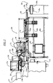
Figure 2 is a more detailed side view of the system shown inFigure 1 with some panels shown transparent to view underlying components; -
Figure 3 is an enlarged, fragmentary side view taken fromFigure 2 ; -
Figure 4 is an enlarged, fragmentary side view taken fromFigure 2 ; -
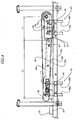
Figure 4A is an enlarged view of a side of an input section of the patty pressing part of the system of the present invention; -
Figure 5 is a fragmentary sectional view taken generally along line 5-5 ofFigure 3 ; -
Figure 5A is a fragmentary sectional view taken generally alongline 5A-5A ofFigure 3 ; -
Figure 6 is an enlarged, fragmentary end view taken fromFigure 5 ; -
Figure 7 is a top view of the patty pressing system ofFigure 4 ; -
Figure 8 is an enlarged, fragmentary view taken fromFigure 7 ; -
Figure 9 is an enlarged, fragmentary view taken fromFigure 7 ; -
Figure10 is a sectional view taken generally along line 10-10 ofFigure 9 ; and -
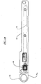
Figure 11 is a sectional view taken generally along line 11-11 ofFigure 9 . - While this invention is susceptible of embodiment in many different forms, there are shown in the drawings, and will be described herein in detail, specific embodiments thereof with the understanding that the present disclosure is to be considered as an exemplification of the principles of the invention and is not intended to limit the invention to the specific embodiments illustrated.
-
Figures 1 and2 illustrate asystem 20 according to the invention. A high-speed foodpatty molding machine 22 is operatively associated with a pressing former 24, ashuttle conveyor 26, and anindexing packaging machine 28. The high-speed molding machine 26 can be a FORMAX® MAXUM700®, F-6™, F-12™, F-19™, F-26™, F-26ULTRA™ or F-400™ reciprocating mold plate forming machine, available from Formax, Inc. of Mokena, Illinois, U.S.A., for supplying patties to the fast food industry. High-speed molding machines are also described for example inU.S. patents 3,887,964 ;4,372,008 ;4,356,595 ;4,821,376 ;4,996,743 , and publishedU.S. Patent Application 2005/0092187 ,U.S. Serial No. 10/942,627 filed September 16, 2004 U.S. Serial Number 60/881,877, filed January 23, 2007 - The
molding machine 22 includes amachine base 21 that supports the operating mechanism formachine 22 and can contain hydraulic actuating systems, electrical actuating systems, and most of the machine controls. Themachine 22 includes a supply means 27 for supplying moldable food material, such as ground beef, fish, or the like, to the processing mechanisms of the machine. - A
control panel 29, such as a touch screen control panel, is arranged on a forward end of theapparatus 22 and communicates with a machine controller. - As generally illustrated in
Figure 2 supply means 27 comprises a large foodmaterial storage hopper 27a that opens into the intake of a food pump system 27b. The food pump system 27b typically includes at least two food pumps that continuously, or intermittently under a pre-selected control scheme, pump food material, under pressure, into avalve manifold 27d that is flow-connected to a cyclically operatedmolding mechanism 27e. - In the operation of
machine 22, a supply of ground beef or other moldable food material is deposited intohopper 27a from overhead. An automated refill device (not shown) can be used to refill the hopper when the supply of food product therein is depleted. The floor ofhopper 27a at least partially closed by a conveyor belt of a conveyor (not shown). The belt includes a top surface for moving the food material longitudinally of thehopper 27a to a hopper forward end. - The food material is moved by supply means 27 into the intake of plunger pumps of pumping system 27b. The pumps of system 27b operate in overlapping alteration to each other; and at any given time when
machine 22 is in operation, at least one of the pumps is forcing food material under pressure into the intake of manifold 27d. - The manifold 27d comprises a path for feeding the food material, still under relatively high pressure, into the
molding mechanism 27e.Molding mechanism 27e operates on a cyclic basis, first sliding a multi-cavity mold plate into a receiving position over manifold 27d and then away from the manifold to a discharge position aligned with a series of knock outcups 27f. When the mold plate is at its discharge position, knock out cups plungers orcups 27f are driven downwardly discharging hamburgers or other molded patties frommachine 22. Preferably asheet interleaver machine 31 is arranged on the outlet of the formingmachine 22. Thesheet interleaver machine 31 is described in detail inU.S. Patent 7,159,372 . Themachine 31 includes a supply ofsheets 31a, asheet shuttle 31b that is arranged to move in synchronism with the mold plate movement between an advanced position beneath the knockout cups and a retracted position. When in the retracted position a pivoting sheet placer 31c places a row of sheets on the shuttle. The shuttle then moves to the advanced position beneath the knockout cups and beneath the mold plate cavities filled with food patties. When the knockout cups are driven downward to displace the patties, thepatties 35 are pushed onto thesheets 37, with the sheets underlying the patties. - The
patties 35 andsheets 37 are pushed onto atop surface 39b of a circulatingbelt 39a of anoutput conveyor 39. Theoutput conveyor 39 includes a supportingframe 40. The supporting frame includes anupper frame level 40a, anintermediate frame level 40b and alower frame level 40c. - The
patty presser 24 is shown in detail inFigures 3-9 . The presser is carried by theframe 40 and is located above theoutput conveyor 39. Alternately, the presser could have a separate lower conveyor that receives patties from the output conveyor. Thepresser 24 includes anupper conveyor 41 that comprises anangular input section 41a and an outputhorizontal section 41b. Theinput section 41a is pivotable to theoutput section 41b about ashaft 43. An input end of theinput section 41a can be adjusted in elevation by afirst elevator mechanism 45. Theentire output section 41b, and including the end of theinput section 41a, can be adjusted in elevation by asecond elevator 47. Theelevators frame 40. - The
elevator mechanisms elevator mechanism 45 will be described. - The
elevator mechanism 45 includes fourcolumns bracket plate 45e is fastened to the lower ends of thecolumns - As shown in
Figures 3 and5 , a threadedshaft 45g is located between thecolumns shaft 45h is located between thecolumns 45c, 45d, offset inwardly. Anut 45j is threaded onto theshaft 45g and anut 45k is threaded onto theshaft 45h. The nuts 45j, 45k are fixed to thebracket plate 45e by keys, or fasteners, or by welding, etc. The nuts 45j, 45k cannot rotate or translate with respect to thebracket plate 45e. - The threaded
shafts first bevel gear 45n, 45o. Thefirst bevel gears 45n, 45o are each enmesh with asecond bevel gear 45p, 45q that are fixedly carried on acrank shaft 45r. Thecrank shaft 45r is journaled onbearings crank handle 45u, 45v is fixed onto opposite ends of thecrank shaft 45r. Thus by turning either of the crank handles 45u, 45v, the nuts 45j, 45k progress up or down theshafts bracket plate 45e up or down which drives thecolumns 45a-45d up or down. - Upper parts of the
columns 45a-45d of theelevator mechanism 45 are fastened to ablock 48 by twofasteners pin 49 is connected to astrut 50 that spans theinput section 41a, and is connected to thesidewalls pin 49 is fit within aslot 48c within theblock 48 so that as the elevation is adjusted, thepin 49 can slide, as necessary, in theslot 48c. Adjusting the elevation of the inlet ends changes the tilt of the input section. - Each of the
columns 45a-45d is guided above thebracket plate 45e by aguide 46 to allow vertical movement only. Theguides 46 are mounted to a sidewall 40aa of theupper frame level 40a. -
Bracket plate 45e is also guided by four support columns: support columns 45aa, 45bb on the near side of the presser 24 (Figure 3 ), and support columns 45cc, 45dd on the far side of the presser 24 (Figure 3 ,Figure 5 ). The four support columns 45aa, 45bb, 45cc, 45dd are arranged in a rectangular grid pattern that is mirror image identical across a vertical, longitudinal center plane of thepresser 24. Only the near side pair of support columns 45aa, 45bb is shown inFigure 3 andFigure 5 with the understanding that the far side pair of columns 45cc, 45dd is mirror image identical and that the four columns 45aa-45dd function identically. - Along the longitudinal direction, the threaded
shaft 45g is between the support columns 45aa, 45bb and the threadedshaft 45h is between the support columns 45cc, 45dd. -
Bracket plate 45e is guided for vertical movement by the support columns 45aa-45dd penetrating corresponding holes in thebracket plate 45e that are each fitted with acylindrical bushing 45 for smooth, precise vertical movement of thebracket plate 45e. The near side columns 45aa, 45bb are mounted to the sidewall 40aa of theupper frame level 40a and to a bottom plate 40bb of theintermediate frame level 40b, via a mounting block 45ee attached with screws 45ff through a spacer 45gg. The far side columns 45cc, 45dd are mounted to a far side sidewall of theupper frame level 40a, and to the bottom plate 40bb of theintermediate frame level 40b in an identical fashion as the near side support columns. - The
patty presser 24 includes anendless belt 52 that surrounds adrive roller 54 and a drivenroller 56. Thedrive roller 54 is preferably a drum motor, such as a drum motor provided by ITOH DENKI. Alternately, the drive roller could be driven by a chain or belt from a dedicated motor of the motor that drives theoutput conveyor 39. - V-shaped
guides belt 52 wrap end pulleys of therollers belt 52 in proper position on therollers backing plate 62 underlies theinput section 41a of thepresser 24. Thisplate 62 extends completely across theinput section 41a and backs up thebelt 52 and exerts a compression force of the patties as they are driven between the twoconveyors plate 62 is mounted toside panels side panels side plates pivot axle 72. The drivenroller 54 is rotationally held by and between theside plates bearings - The
roller 56 is mounted for rotation onside plates bearings 71c, 70d. Theside plates side panels figure 10 ) that are arranged on opposite sides of theinput section 41a. Each tensioningassembly 72 comprises ananchor 73 fastened to thesidewall anchor 73 and has its head butt against ablock 75. The block 74 is connected to aslide block 76 by both being penetrated by thepin 49. Theslide block 76 slides within aslot 77 in thesidewalls side plates strut 50. Thus, extension of the bolt 74, 74 on both sides of theinput section 41a, out of therespective anchor side plates sidewalls belt 52 on therollers - Upper parts of the
columns 45a-45d of each of theelevator mechanisms 47 are fastened to ablock 80 which is guided for straight vertical movement by aspindle 82. Oneblock 80 is fastened to each of therespective side plates roller 54 is rotationally held by and between theside plates block 80 elevates theside plates roller 54. Adjusting the elevation of theoutlet section 41b also changes the elevation of the end of theinput section 41b and also the final thickness of the patties. - The
output conveyor belt 39a and theupper conveyor belt 54 circulate in opposite directions such that facingbelt surfaces patty pressing path 75 therebetween. - As illustrated in
Figure 4 , the clearance A between the facingsurfaces path 75 is equal or greater to the height of thepatty 35 plussheet 37. Thesurface 54a declines along thepath 75 in theinput section 41a for a distance L1 to a clearance of B, squeezing thepatty 35 down to approximately this height. The patty is then more gently squeezed in the last section of thepath 75 corresponding to thehorizontal section 41b for a distance L2. Due to this squeezing of the patty between thebelts - According to one exemplary embodiment, L1= 22 inches, L2= 9 inches, A= 1.5 inches and B= .5 inches for a patty that has an initial diameter of 3 inches and a final diameter of 4.5 inches.
- The
shuttle conveyor 26 can be as described inU.S. Patents 6,669,005 or7,065,936 . The shuttle conveyors in these patents are conveyors wherein the end of the circulating conveyor belt can be retracted or extended to deposit a patty into one or more rows onto a conveyor having a running direction arranged parallel to, or perpendicular to, the running direction of the shuttle conveyor. Also, the end of the shuttle conveyor is movable to ensure aligned stacking of the patty/sheet interleaved products. - The
packaging machine 28 delivers empty packages, such as trays formed in a continuous train, to afill station 28a beneath the end of the shuttle conveyor. Preferably, the trays are placed onto anendless belt conveyor 28b having spacing ribs orwalls 28c at regularly spaced intervals that correspond to the patty output from theshuttle conveyor 26. Theshuttle conveyor 26 can be controlled to stack interleaved patties and sheets continuously into the trays until the allotted number per tray is stacked in the tray. The trays are then indexed in synchronism with the shuttle conveyor and the rest of the equipment, to bring new empty trays into the fillingstation 28a. In this regard, thepackaging machine 28 can be in signal-communication with the control of the patty-forming machine and shuttle conveyor.
Claims (6)
- A patty presser (24), comprising:an upper conveyor having an upper endless belt (52) and a lower conveyor comprising a lower endless belt (39a), said lower conveyor receiving patties (35), said upper conveyor located above said lower conveyor, facing belt surfaces (54a, 39b) of said upper and lower endless belts (52, 39a) defining a path (75) between said upper and lower conveyors, said upper and lower endless belts (52, 39a) circulating in opposite directions, said upper conveyor having an inlet length (L1) of said facing belt surface (54a) of said upper endless belt (52) being tilted such that a first clearance (A) at an input to said path (75) is equal to or greater than a thickness of said patties (35) and a second clearance (B) at an outlet of said inlet length (L1) is less than a thickness of said patties (35) at said input of said path (75), wherein said upper conveyor comprises a horizontal section (41b) from an end of said inlet length (L1) to the end of said path (75),said upper conveyor comprises backing plate (62) above said inlet length (L1) of said facing surface of said upper endless belt (52),the patty presser further comprising a first elevator mechanism (45), wherein said inlet length (L1) of said upper endless belt (52) is adjustable in tilt by action of said first elevator (45).
- The presser according to claim 1, comprising a second elevator mechanism (47), wherein said clearance (B) between said facing belt surfaces (54a, 39b) at an end of said path is adjustable by action of said second elevator mechanism (47).
- A system for forming patties having a hand-formed appearance, comprising,
a high speed patty forming machine (22) having a reciprocating mold plate with mold cavities, said mold plate reciprocating between a patty fill position wherein food product under pressure fills said cavities and a discharge position where a plurality of knockout cups (27f) displace said patties (35) from said cavities downward onto an output conveyor (39) portion; and
a patty presser (24) comprising:an upper conveyor having an upper endless belt (52) and a lower conveyor comprising a lower endless belt (39a), said lower conveyor receiving patties (35), said upper conveyor located above said lower conveyor, facing belt surfaces (54a, 39b) of said upper and lower endless belts (52, 39a) defining a path (75) between said upper and lower conveyors, said upper and lower endless belts (52, 39a) circulating in opposite directions, said upper conveyor having an inlet length (L1) of said facing belt surface (54a) of said upper endless belt (52) being tilted such that a first clearance (A) at an input to said path (75) is equal to or greater than a thickness of said patties (35) and a second clearance (B) at an outlet of said inlet length (L1) is less than a thickness of said patties (35) at said input of said path (75), characterised in thatsaid upper conveyor comprises a horizontal section (41b) from an end of said inlet length (L1) to the end of said path (75), wherein said lower conveyor receiving patties from said output conveyor (39) portion. - System according to claim 3, further comprising a shuttle conveyor (26) arranged at said output of said path (75) and an indexing packaging machine that at a filling station (28a) presents open packages to be filled and once filled, indexes said packages away from said filling station (28a) to and delivers new open packages to said filling station (28a), said shuttle conveyor (26a) delivering patties (35) to said filling station (28a).
- System according to claim 3, wherein said output conveyor portion (39) and said lower conveyor are formed by a single endless belt.
- Use of a patty presser (24) according to claim 1.
Applications Claiming Priority (3)
| Application Number | Priority Date | Filing Date | Title |
|---|---|---|---|
| US88187807P | 2007-01-23 | 2007-01-23 | |
| US12/009,616 US7677880B2 (en) | 2007-01-23 | 2008-01-19 | Apparatus for forming hand-formed style patty using a patty-forming machine |
| PCT/US2008/000872 WO2008091634A2 (en) | 2007-01-23 | 2008-01-22 | Apparatus for forming hand-formed style patty using a patty-forming machine |
Publications (4)
| Publication Number | Publication Date |
|---|---|
| EP2131660A2 EP2131660A2 (en) | 2009-12-16 |
| EP2131660A4 EP2131660A4 (en) | 2013-06-26 |
| EP2131660B1 EP2131660B1 (en) | 2014-10-15 |
| EP2131660B2 true EP2131660B2 (en) | 2018-07-04 |
Family
ID=39645066
Family Applications (1)
| Application Number | Title | Priority Date | Filing Date |
|---|---|---|---|
| EP08724725.0A Active EP2131660B2 (en) | 2007-01-23 | 2008-01-22 | Apparatus for forming hand-formed style patty using a patty-forming machine |
Country Status (6)
| Country | Link |
|---|---|
| US (1) | US7677880B2 (en) |
| EP (1) | EP2131660B2 (en) |
| CA (1) | CA2676389A1 (en) |
| DK (1) | DK2131660T4 (en) |
| ES (1) | ES2526350T5 (en) |
| WO (1) | WO2008091634A2 (en) |
Families Citing this family (20)
| Publication number | Priority date | Publication date | Assignee | Title |
|---|---|---|---|---|
| US8840390B2 (en) * | 2007-06-29 | 2014-09-23 | Risco Usa Corporation | Machine for the production of formed patties with a hand made appearance, and method for interleaving paper and stacking |
| FR2964833B1 (en) * | 2010-09-20 | 2012-10-12 | Marel Stork Food Systems France Sas | FOOD PRODUCT PORTION FORMING MACHINE WITH INTERCALLE PAPER APPLICATION DEVICE |
| EP2449893B1 (en) | 2010-11-04 | 2016-08-17 | GEA Food Solutions Bakel B.V. | Mass distribution device and molding device |
| EP2468104B1 (en) | 2010-12-23 | 2018-09-12 | GEA Food Solutions Bakel B.V. | Cleaning method for a mould drum |
| EP2478771B1 (en) * | 2011-01-25 | 2015-04-08 | GEA Food Solutions Bakel B.V. | Food production line |
| BR112013020390B1 (en) | 2011-02-10 | 2018-11-13 | Gea Food Solutions Bakel B.V. | food forming drum |
| US9392800B2 (en) | 2011-03-10 | 2016-07-19 | Tomahawk Manufacturing, Inc. | Diagonal linkage knock out |
| EP3409124B1 (en) | 2011-07-25 | 2025-01-22 | GEA Food Solutions Bakel B.V. | Food forming apparatus with a food feed member |
| BR112014017609B1 (en) | 2012-01-20 | 2019-12-03 | Gea Food Solutions Bakel Bv | system for forming a product from a pasta and method for feeding a pasta with a feed pump |
| FR2991853B1 (en) * | 2012-06-18 | 2015-11-13 | Adiv Dev | PROCESS FOR THE CONTINUOUS MANUFACTURE OF PASTEURIZED DRIED SEASONED, RECONSTITUTED THIN-PLATED MEAT AND INSTALLATION FOR CARRYING OUT SAID PROCESS |
| PL3639668T3 (en) | 2013-02-01 | 2021-12-20 | Gea Food Solutions Bakel B.V. | Food molding drum |
| RU2655814C2 (en) | 2013-05-03 | 2018-05-29 | Геа Фуд Сольюшнс Бакел Б.В. | Sealing member for a food forming drum |
| DE102015103423B4 (en) * | 2015-03-09 | 2017-11-30 | Vemag Maschinenbau Gmbh | System for shaping and conveying food products of pasty mass |
| PL3267799T3 (en) | 2015-03-13 | 2020-11-16 | Gea Food Solutions Bakel B.V. | Method for cleaning and storing of a mould drum |
| EP3180989B1 (en) | 2015-12-16 | 2020-02-05 | Albert Handtmann Maschinenfabrik GmbH & Co. KG | Method and device for the production of food products, in particular casing-less products of a specific shape |
| DE102020103304A1 (en) * | 2020-02-10 | 2021-08-12 | Tpv Gmbh | Apparatus and method for forming a strand-shaped foodstuff |
| CN115279190B (en) | 2020-03-10 | 2023-11-21 | 马瑞奥深加工私人有限公司 | Production of three-dimensional products from bulk pumpable fiber food material |
| CN111301796B (en) * | 2020-03-23 | 2025-08-08 | 深圳市佳士机器人科技有限公司 | Fish bait automatic packaging system |
| CN115812761B (en) * | 2022-12-08 | 2025-12-16 | 漳州英博机械制造有限公司 | Automatic meat mud rounding machine based on food flaking processing |
| CN116849380B (en) * | 2023-09-04 | 2023-11-21 | 云南旭众机械设备有限公司 | Bait piece production processingequipment of convenient transportation |
Citations (3)
| Publication number | Priority date | Publication date | Assignee | Title |
|---|---|---|---|---|
| US2070950A (en) † | 1935-07-27 | 1937-02-16 | Rca Corp | Code signaling |
| WO2004093548A2 (en) † | 2003-04-22 | 2004-11-04 | General Mills Marketing, Inc. | Apparatus and method for forming food products by gradual compression |
| EP1797761A1 (en) † | 2005-12-16 | 2007-06-20 | Poly-clip System GmbH & Co. KG | Method and device for redistribution of paste filling |
Family Cites Families (26)
| Publication number | Priority date | Publication date | Assignee | Title |
|---|---|---|---|---|
| US2070850A (en) | 1935-11-15 | 1937-02-16 | Frank W Trabold | Meat product |
| US2528125A (en) | 1945-03-12 | 1950-10-31 | Frank S Elsaesser | Hamburg steak patty forming machine |
| US2509971A (en) | 1945-05-11 | 1950-05-30 | Frank S Elsaesser | Hamburg steak patty forming machine |
| US2634458A (en) | 1946-10-11 | 1953-04-14 | Frank S Elsaesser | Hamburg steak patty forming machine |
| US3734007A (en) | 1971-03-01 | 1973-05-22 | Hygrade Food Products Corp | Conveyor press |
| US3887964A (en) | 1972-01-24 | 1975-06-10 | Formax Inc | Food patty molding machine |
| US4035982A (en) | 1976-10-29 | 1977-07-19 | Excel Engineering, Inc. | Automatic vacuum packaging machine and method |
| US4137604A (en) * | 1977-11-02 | 1979-02-06 | Formax, Inc. | Processor-stacker for papered food patties and like layered objects |
| US4229859A (en) | 1978-05-01 | 1980-10-28 | Gagliardi Bros., Inc. | Meat patty processing method and apparatus |
| SE433425B (en) | 1980-05-07 | 1984-05-28 | Food Technology Co Ab | SET AND DEVICE FOR THE PREPARATION OF THIN, FOR FRYING OR GRILLING, EASY DISCS OF FROZEN MEAT |
| US4356595A (en) | 1980-11-07 | 1982-11-02 | Formax, Inc. | Method and apparatus for molding food patties |
| US4372008A (en) | 1981-04-23 | 1983-02-08 | Formax, Inc. | Food patty molding machine with multi-orifice fill passage and stripper plate |
| US4514434A (en) | 1983-04-21 | 1985-04-30 | Goldberger Foods Inc. | Meat patty and process for forming the same |
| US4516291A (en) | 1983-05-31 | 1985-05-14 | Goldberger Foods Inc. | Apparatus and process for forming meat patties |
| US5037350A (en) | 1984-12-14 | 1991-08-06 | Hardee's Food Systems, Inc. | Method and apparatus for forming meat patties having a closer-to-handformed appearance and texture |
| US4821376A (en) | 1988-06-02 | 1989-04-18 | Formax, Inc. | Seal-off for food patty molding machine with multi-orifice fill passage and stripper plate |
| US4996743A (en) | 1990-01-29 | 1991-03-05 | Formax, Inc. | Mold plate drive linkage |
| DE4301594C2 (en) * | 1993-01-21 | 2002-10-31 | Dieffenbacher Gmbh Maschf | Process and plant for the production of chipboard |
| US5809745A (en) * | 1995-06-07 | 1998-09-22 | Excel Corporation | Apparatus and method for stacking and packing articles |
| US5811146A (en) | 1996-01-11 | 1998-09-22 | Kraft Foods, Inc. | Method for producing flat processed meat products |
| JP2001198939A (en) * | 2000-01-21 | 2001-07-24 | Jsp Corp | Apparatus for manufacturing foam moldings |
| JP2001225309A (en) | 2000-02-15 | 2001-08-21 | Matsushita Electric Works Ltd | Method for manufacturing cement fiber board |
| US7048825B2 (en) | 2002-10-03 | 2006-05-23 | Weyerhaeuser Company | Microwave preheat press assembly |
| US7125245B2 (en) | 2003-09-16 | 2006-10-24 | Formax, Inc. | Tube valve arrangement for a patty-forming machine |
| CA2550531C (en) | 2003-09-16 | 2013-03-26 | Formax, Inc. | Drive systems for a reciprocating mold plate patty-forming machine |
| US7159372B2 (en) | 2004-01-27 | 2007-01-09 | Formax, Inc. | Sheet interleave system for patty-forming apparatus |
-
2008
- 2008-01-19 US US12/009,616 patent/US7677880B2/en active Active
- 2008-01-22 DK DK08724725.0T patent/DK2131660T4/en active
- 2008-01-22 ES ES08724725.0T patent/ES2526350T5/en active Active
- 2008-01-22 CA CA002676389A patent/CA2676389A1/en not_active Abandoned
- 2008-01-22 EP EP08724725.0A patent/EP2131660B2/en active Active
- 2008-01-22 WO PCT/US2008/000872 patent/WO2008091634A2/en not_active Ceased
Patent Citations (3)
| Publication number | Priority date | Publication date | Assignee | Title |
|---|---|---|---|---|
| US2070950A (en) † | 1935-07-27 | 1937-02-16 | Rca Corp | Code signaling |
| WO2004093548A2 (en) † | 2003-04-22 | 2004-11-04 | General Mills Marketing, Inc. | Apparatus and method for forming food products by gradual compression |
| EP1797761A1 (en) † | 2005-12-16 | 2007-06-20 | Poly-clip System GmbH & Co. KG | Method and device for redistribution of paste filling |
Also Published As
| Publication number | Publication date |
|---|---|
| WO2008091634A3 (en) | 2010-03-11 |
| DK2131660T4 (en) | 2018-10-15 |
| ES2526350T5 (en) | 2018-11-02 |
| CA2676389A1 (en) | 2008-07-31 |
| US7677880B2 (en) | 2010-03-16 |
| EP2131660A4 (en) | 2013-06-26 |
| ES2526350T3 (en) | 2015-01-09 |
| DK2131660T3 (en) | 2015-01-12 |
| EP2131660A2 (en) | 2009-12-16 |
| US20080220116A1 (en) | 2008-09-11 |
| WO2008091634A2 (en) | 2008-07-31 |
| EP2131660B1 (en) | 2014-10-15 |
Similar Documents
| Publication | Publication Date | Title |
|---|---|---|
| EP2131660B1 (en) | Apparatus for forming hand-formed style patty using a patty-forming machine | |
| EP0496768B1 (en) | Food molding and portioning apparatus | |
| US4054967A (en) | Food patty molding machine | |
| US7788885B2 (en) | Method of loading food stacks | |
| US7229277B2 (en) | Mold cover lift system for a patty-forming apparatus | |
| JP4127738B2 (en) | Raw wood slicer for ham etc. | |
| US4372008A (en) | Food patty molding machine with multi-orifice fill passage and stripper plate | |
| US4317259A (en) | Molding apparatus | |
| TWM618437U (en) | Meat-floss egg roll filling machine structure | |
| CA2600022A1 (en) | Loaf seam synchronization device for continuous loaf feed slicing machine | |
| US20100209575A1 (en) | Linear Actuator Assisted Knockout Mechanism for a Food Patty Forming Machine | |
| US3416187A (en) | Patty molding machine | |
| US9661860B2 (en) | Meatball rolling machine | |
| US3780193A (en) | Production of waffles and like food products | |
| CN219565528U (en) | Automatic discharging device for small beef jerky packages | |
| CN114223681B (en) | Wrapping point forming production line | |
| US9392800B2 (en) | Diagonal linkage knock out | |
| US20060037284A1 (en) | Food stacking loading apparatus | |
| EP0363816B1 (en) | Machine for the automatic production of portions of toasted bread slices | |
| RU231923U1 (en) | GINGERBREAD MAKING MACHINE | |
| RU231073U1 (en) | JIGGING AND DOSING MACHINE | |
| JP3668917B2 (en) | Multilayer food manufacturing method and apparatus | |
| CA1266800A (en) | Rolling station for food processing apparatus |
Legal Events
| Date | Code | Title | Description |
|---|---|---|---|
| PUAI | Public reference made under article 153(3) epc to a published international application that has entered the european phase |
Free format text: ORIGINAL CODE: 0009012 |
|
| 17P | Request for examination filed |
Effective date: 20091016 |
|
| AK | Designated contracting states |
Kind code of ref document: A2 Designated state(s): AT BE BG CH CY CZ DE DK EE ES FI FR GB GR HR HU IE IS IT LI LT LU LV MC MT NL NO PL PT RO SE SI SK TR |
|
| R17D | Deferred search report published (corrected) |
Effective date: 20100311 |
|
| RIC1 | Information provided on ipc code assigned before grant |
Ipc: A22C 7/00 20060101AFI20100507BHEP |
|
| DAX | Request for extension of the european patent (deleted) | ||
| A4 | Supplementary search report drawn up and despatched |
Effective date: 20130528 |
|
| RIC1 | Information provided on ipc code assigned before grant |
Ipc: A22C 7/00 20060101AFI20130522BHEP |
|
| GRAP | Despatch of communication of intention to grant a patent |
Free format text: ORIGINAL CODE: EPIDOSNIGR1 |
|
| INTG | Intention to grant announced |
Effective date: 20140519 |
|
| GRAS | Grant fee paid |
Free format text: ORIGINAL CODE: EPIDOSNIGR3 |
|
| GRAA | (expected) grant |
Free format text: ORIGINAL CODE: 0009210 |
|
| AK | Designated contracting states |
Kind code of ref document: B1 Designated state(s): AT BE BG CH CY CZ DE DK EE ES FI FR GB GR HR HU IE IS IT LI LT LU LV MC MT NL NO PL PT RO SE SI SK TR |
|
| REG | Reference to a national code |
Ref country code: GB Ref legal event code: FG4D Ref country code: CH Ref legal event code: EP |
|
| REG | Reference to a national code |
Ref country code: IE Ref legal event code: FG4D |
|
| REG | Reference to a national code |
Ref country code: AT Ref legal event code: REF Ref document number: 691217 Country of ref document: AT Kind code of ref document: T Effective date: 20141115 |
|
| REG | Reference to a national code |
Ref country code: DE Ref legal event code: R096 Ref document number: 602008034900 Country of ref document: DE Effective date: 20141127 |
|
| REG | Reference to a national code |
Ref country code: ES Ref legal event code: FG2A Ref document number: 2526350 Country of ref document: ES Kind code of ref document: T3 Effective date: 20150109 |
|
| REG | Reference to a national code |
Ref country code: DK Ref legal event code: T3 Effective date: 20150108 |
|
| REG | Reference to a national code |
Ref country code: NL Ref legal event code: T3 |
|
| REG | Reference to a national code |
Ref country code: AT Ref legal event code: MK05 Ref document number: 691217 Country of ref document: AT Kind code of ref document: T Effective date: 20141015 |
|
| REG | Reference to a national code |
Ref country code: LT Ref legal event code: MG4D |
|
| PG25 | Lapsed in a contracting state [announced via postgrant information from national office to epo] |
Ref country code: NO Free format text: LAPSE BECAUSE OF FAILURE TO SUBMIT A TRANSLATION OF THE DESCRIPTION OR TO PAY THE FEE WITHIN THE PRESCRIBED TIME-LIMIT Effective date: 20150115 Ref country code: IS Free format text: LAPSE BECAUSE OF FAILURE TO SUBMIT A TRANSLATION OF THE DESCRIPTION OR TO PAY THE FEE WITHIN THE PRESCRIBED TIME-LIMIT Effective date: 20150215 Ref country code: LT Free format text: LAPSE BECAUSE OF FAILURE TO SUBMIT A TRANSLATION OF THE DESCRIPTION OR TO PAY THE FEE WITHIN THE PRESCRIBED TIME-LIMIT Effective date: 20141015 Ref country code: PT Free format text: LAPSE BECAUSE OF FAILURE TO SUBMIT A TRANSLATION OF THE DESCRIPTION OR TO PAY THE FEE WITHIN THE PRESCRIBED TIME-LIMIT Effective date: 20150216 Ref country code: FI Free format text: LAPSE BECAUSE OF FAILURE TO SUBMIT A TRANSLATION OF THE DESCRIPTION OR TO PAY THE FEE WITHIN THE PRESCRIBED TIME-LIMIT Effective date: 20141015 |
|
| PG25 | Lapsed in a contracting state [announced via postgrant information from national office to epo] |
Ref country code: HR Free format text: LAPSE BECAUSE OF FAILURE TO SUBMIT A TRANSLATION OF THE DESCRIPTION OR TO PAY THE FEE WITHIN THE PRESCRIBED TIME-LIMIT Effective date: 20141015 Ref country code: AT Free format text: LAPSE BECAUSE OF FAILURE TO SUBMIT A TRANSLATION OF THE DESCRIPTION OR TO PAY THE FEE WITHIN THE PRESCRIBED TIME-LIMIT Effective date: 20141015 Ref country code: CY Free format text: LAPSE BECAUSE OF FAILURE TO SUBMIT A TRANSLATION OF THE DESCRIPTION OR TO PAY THE FEE WITHIN THE PRESCRIBED TIME-LIMIT Effective date: 20141015 Ref country code: GR Free format text: LAPSE BECAUSE OF FAILURE TO SUBMIT A TRANSLATION OF THE DESCRIPTION OR TO PAY THE FEE WITHIN THE PRESCRIBED TIME-LIMIT Effective date: 20150116 Ref country code: SE Free format text: LAPSE BECAUSE OF FAILURE TO SUBMIT A TRANSLATION OF THE DESCRIPTION OR TO PAY THE FEE WITHIN THE PRESCRIBED TIME-LIMIT Effective date: 20141015 Ref country code: LV Free format text: LAPSE BECAUSE OF FAILURE TO SUBMIT A TRANSLATION OF THE DESCRIPTION OR TO PAY THE FEE WITHIN THE PRESCRIBED TIME-LIMIT Effective date: 20141015 Ref country code: PL Free format text: LAPSE BECAUSE OF FAILURE TO SUBMIT A TRANSLATION OF THE DESCRIPTION OR TO PAY THE FEE WITHIN THE PRESCRIBED TIME-LIMIT Effective date: 20141015 |
|
| REG | Reference to a national code |
Ref country code: DE Ref legal event code: R026 Ref document number: 602008034900 Country of ref document: DE |
|
| PLBI | Opposition filed |
Free format text: ORIGINAL CODE: 0009260 |
|
| PG25 | Lapsed in a contracting state [announced via postgrant information from national office to epo] |
Ref country code: SK Free format text: LAPSE BECAUSE OF FAILURE TO SUBMIT A TRANSLATION OF THE DESCRIPTION OR TO PAY THE FEE WITHIN THE PRESCRIBED TIME-LIMIT Effective date: 20141015 Ref country code: RO Free format text: LAPSE BECAUSE OF FAILURE TO SUBMIT A TRANSLATION OF THE DESCRIPTION OR TO PAY THE FEE WITHIN THE PRESCRIBED TIME-LIMIT Effective date: 20141015 Ref country code: CZ Free format text: LAPSE BECAUSE OF FAILURE TO SUBMIT A TRANSLATION OF THE DESCRIPTION OR TO PAY THE FEE WITHIN THE PRESCRIBED TIME-LIMIT Effective date: 20141015 Ref country code: EE Free format text: LAPSE BECAUSE OF FAILURE TO SUBMIT A TRANSLATION OF THE DESCRIPTION OR TO PAY THE FEE WITHIN THE PRESCRIBED TIME-LIMIT Effective date: 20141015 |
|
| 26 | Opposition filed |
Opponent name: MAREL TOWNSEND FURTHER PROCESSING B.V. Effective date: 20150714 |
|
| REG | Reference to a national code |
Ref country code: CH Ref legal event code: PL |
|
| PG25 | Lapsed in a contracting state [announced via postgrant information from national office to epo] |
Ref country code: LU Free format text: LAPSE BECAUSE OF FAILURE TO SUBMIT A TRANSLATION OF THE DESCRIPTION OR TO PAY THE FEE WITHIN THE PRESCRIBED TIME-LIMIT Effective date: 20150122 |
|
| PLAX | Notice of opposition and request to file observation + time limit sent |
Free format text: ORIGINAL CODE: EPIDOSNOBS2 |
|
| PG25 | Lapsed in a contracting state [announced via postgrant information from national office to epo] |
Ref country code: MC Free format text: LAPSE BECAUSE OF FAILURE TO SUBMIT A TRANSLATION OF THE DESCRIPTION OR TO PAY THE FEE WITHIN THE PRESCRIBED TIME-LIMIT Effective date: 20141015 |
|
| PG25 | Lapsed in a contracting state [announced via postgrant information from national office to epo] |
Ref country code: LI Free format text: LAPSE BECAUSE OF NON-PAYMENT OF DUE FEES Effective date: 20150131 Ref country code: CH Free format text: LAPSE BECAUSE OF NON-PAYMENT OF DUE FEES Effective date: 20150131 |
|
| REG | Reference to a national code |
Ref country code: IE Ref legal event code: MM4A |
|
| PLAF | Information modified related to communication of a notice of opposition and request to file observations + time limit |
Free format text: ORIGINAL CODE: EPIDOSCOBS2 |
|
| REG | Reference to a national code |
Ref country code: FR Ref legal event code: PLFP Year of fee payment: 9 |
|
| PG25 | Lapsed in a contracting state [announced via postgrant information from national office to epo] |
Ref country code: IE Free format text: LAPSE BECAUSE OF NON-PAYMENT OF DUE FEES Effective date: 20150122 |
|
| PG25 | Lapsed in a contracting state [announced via postgrant information from national office to epo] |
Ref country code: SI Free format text: LAPSE BECAUSE OF FAILURE TO SUBMIT A TRANSLATION OF THE DESCRIPTION OR TO PAY THE FEE WITHIN THE PRESCRIBED TIME-LIMIT Effective date: 20141015 |
|
| PLBB | Reply of patent proprietor to notice(s) of opposition received |
Free format text: ORIGINAL CODE: EPIDOSNOBS3 |
|
| PG25 | Lapsed in a contracting state [announced via postgrant information from national office to epo] |
Ref country code: MT Free format text: LAPSE BECAUSE OF FAILURE TO SUBMIT A TRANSLATION OF THE DESCRIPTION OR TO PAY THE FEE WITHIN THE PRESCRIBED TIME-LIMIT Effective date: 20141015 |
|
| REG | Reference to a national code |
Ref country code: FR Ref legal event code: PLFP Year of fee payment: 10 |
|
| PG25 | Lapsed in a contracting state [announced via postgrant information from national office to epo] |
Ref country code: BG Free format text: LAPSE BECAUSE OF FAILURE TO SUBMIT A TRANSLATION OF THE DESCRIPTION OR TO PAY THE FEE WITHIN THE PRESCRIBED TIME-LIMIT Effective date: 20141015 Ref country code: HU Free format text: LAPSE BECAUSE OF FAILURE TO SUBMIT A TRANSLATION OF THE DESCRIPTION OR TO PAY THE FEE WITHIN THE PRESCRIBED TIME-LIMIT; INVALID AB INITIO Effective date: 20080122 |
|
| PG25 | Lapsed in a contracting state [announced via postgrant information from national office to epo] |
Ref country code: TR Free format text: LAPSE BECAUSE OF FAILURE TO SUBMIT A TRANSLATION OF THE DESCRIPTION OR TO PAY THE FEE WITHIN THE PRESCRIBED TIME-LIMIT Effective date: 20141015 |
|
| PG25 | Lapsed in a contracting state [announced via postgrant information from national office to epo] |
Ref country code: BE Free format text: LAPSE BECAUSE OF FAILURE TO SUBMIT A TRANSLATION OF THE DESCRIPTION OR TO PAY THE FEE WITHIN THE PRESCRIBED TIME-LIMIT Effective date: 20141015 |
|
| APBM | Appeal reference recorded |
Free format text: ORIGINAL CODE: EPIDOSNREFNO |
|
| APBP | Date of receipt of notice of appeal recorded |
Free format text: ORIGINAL CODE: EPIDOSNNOA2O |
|
| APAH | Appeal reference modified |
Free format text: ORIGINAL CODE: EPIDOSCREFNO |
|
| APBU | Appeal procedure closed |
Free format text: ORIGINAL CODE: EPIDOSNNOA9O |
|
| REG | Reference to a national code |
Ref country code: FR Ref legal event code: PLFP Year of fee payment: 11 |
|
| PUAH | Patent maintained in amended form |
Free format text: ORIGINAL CODE: 0009272 |
|
| STAA | Information on the status of an ep patent application or granted ep patent |
Free format text: STATUS: PATENT MAINTAINED AS AMENDED |
|
| 27A | Patent maintained in amended form |
Effective date: 20180704 |
|
| AK | Designated contracting states |
Kind code of ref document: B2 Designated state(s): AT BE BG CH CY CZ DE DK EE ES FI FR GB GR HR HU IE IS IT LI LT LU LV MC MT NL NO PL PT RO SE SI SK TR |
|
| REG | Reference to a national code |
Ref country code: DE Ref legal event code: R102 Ref document number: 602008034900 Country of ref document: DE |
|
| REG | Reference to a national code |
Ref country code: NL Ref legal event code: FP |
|
| REG | Reference to a national code |
Ref country code: DK Ref legal event code: T4 Effective date: 20181008 |
|
| REG | Reference to a national code |
Ref country code: ES Ref legal event code: DC2A Ref document number: 2526350 Country of ref document: ES Kind code of ref document: T5 Effective date: 20181102 |
|
| PGFP | Annual fee paid to national office [announced via postgrant information from national office to epo] |
Ref country code: CH Payment date: 20190215 Year of fee payment: 12 Ref country code: ES Payment date: 20190201 Year of fee payment: 12 Ref country code: GB Payment date: 20190128 Year of fee payment: 12 Ref country code: FR Payment date: 20190125 Year of fee payment: 12 |
|
| PGFP | Annual fee paid to national office [announced via postgrant information from national office to epo] |
Ref country code: DK Payment date: 20190129 Year of fee payment: 12 |
|
| REG | Reference to a national code |
Ref country code: DK Ref legal event code: EBP Effective date: 20200131 |
|
| GBPC | Gb: european patent ceased through non-payment of renewal fee |
Effective date: 20200122 |
|
| PG25 | Lapsed in a contracting state [announced via postgrant information from national office to epo] |
Ref country code: GB Free format text: LAPSE BECAUSE OF NON-PAYMENT OF DUE FEES Effective date: 20200122 Ref country code: FR Free format text: LAPSE BECAUSE OF NON-PAYMENT OF DUE FEES Effective date: 20200131 |
|
| PG25 | Lapsed in a contracting state [announced via postgrant information from national office to epo] |
Ref country code: DK Free format text: LAPSE BECAUSE OF NON-PAYMENT OF DUE FEES Effective date: 20200131 Ref country code: IT Free format text: LAPSE BECAUSE OF NON-PAYMENT OF DUE FEES Effective date: 20200122 |
|
| REG | Reference to a national code |
Ref country code: ES Ref legal event code: FD2A Effective date: 20210604 |
|
| PG25 | Lapsed in a contracting state [announced via postgrant information from national office to epo] |
Ref country code: ES Free format text: LAPSE BECAUSE OF NON-PAYMENT OF DUE FEES Effective date: 20200123 |
|
| P01 | Opt-out of the competence of the unified patent court (upc) registered |
Effective date: 20230425 |
|
| PGFP | Annual fee paid to national office [announced via postgrant information from national office to epo] |
Ref country code: NL Payment date: 20260126 Year of fee payment: 19 |
|
| PGFP | Annual fee paid to national office [announced via postgrant information from national office to epo] |
Ref country code: DE Payment date: 20260128 Year of fee payment: 19 |