EP2131571A1 - Digital video camera with projector mechanism - Google Patents
Digital video camera with projector mechanism Download PDFInfo
- Publication number
- EP2131571A1 EP2131571A1 EP08157814A EP08157814A EP2131571A1 EP 2131571 A1 EP2131571 A1 EP 2131571A1 EP 08157814 A EP08157814 A EP 08157814A EP 08157814 A EP08157814 A EP 08157814A EP 2131571 A1 EP2131571 A1 EP 2131571A1
- Authority
- EP
- European Patent Office
- Prior art keywords
- camera
- unit
- projector mechanism
- enclosure
- processing unit
- Prior art date
- Legal status (The legal status is an assumption and is not a legal conclusion. Google has not performed a legal analysis and makes no representation as to the accuracy of the status listed.)
- Withdrawn
Links
- 238000000034 method Methods 0.000 description 4
- 238000006243 chemical reaction Methods 0.000 description 1
- 230000006870 function Effects 0.000 description 1
- 238000012986 modification Methods 0.000 description 1
- 230000004048 modification Effects 0.000 description 1
Images


Classifications
-
- G—PHYSICS
- G03—PHOTOGRAPHY; CINEMATOGRAPHY; ANALOGOUS TECHNIQUES USING WAVES OTHER THAN OPTICAL WAVES; ELECTROGRAPHY; HOLOGRAPHY
- G03B—APPARATUS OR ARRANGEMENTS FOR TAKING PHOTOGRAPHS OR FOR PROJECTING OR VIEWING THEM; APPARATUS OR ARRANGEMENTS EMPLOYING ANALOGOUS TECHNIQUES USING WAVES OTHER THAN OPTICAL WAVES; ACCESSORIES THEREFOR
- G03B17/00—Details of cameras or camera bodies; Accessories therefor
- G03B17/48—Details of cameras or camera bodies; Accessories therefor adapted for combination with other photographic or optical apparatus
- G03B17/54—Details of cameras or camera bodies; Accessories therefor adapted for combination with other photographic or optical apparatus with projector
-
- H—ELECTRICITY
- H04—ELECTRIC COMMUNICATION TECHNIQUE
- H04N—PICTORIAL COMMUNICATION, e.g. TELEVISION
- H04N23/00—Cameras or camera modules comprising electronic image sensors; Control thereof
- H04N23/50—Constructional details
- H04N23/53—Constructional details of electronic viewfinders, e.g. rotatable or detachable
- H04N23/531—Constructional details of electronic viewfinders, e.g. rotatable or detachable being rotatable or detachable
-
- H—ELECTRICITY
- H04—ELECTRIC COMMUNICATION TECHNIQUE
- H04N—PICTORIAL COMMUNICATION, e.g. TELEVISION
- H04N9/00—Details of colour television systems
- H04N9/12—Picture reproducers
- H04N9/31—Projection devices for colour picture display, e.g. using electronic spatial light modulators [ESLM]
- H04N9/3141—Constructional details thereof
- H04N9/3173—Constructional details thereof wherein the projection device is specially adapted for enhanced portability
-
- H—ELECTRICITY
- H04—ELECTRIC COMMUNICATION TECHNIQUE
- H04N—PICTORIAL COMMUNICATION, e.g. TELEVISION
- H04N9/00—Details of colour television systems
- H04N9/12—Picture reproducers
- H04N9/31—Projection devices for colour picture display, e.g. using electronic spatial light modulators [ESLM]
- H04N9/3141—Constructional details thereof
- H04N9/3173—Constructional details thereof wherein the projection device is specially adapted for enhanced portability
- H04N9/3176—Constructional details thereof wherein the projection device is specially adapted for enhanced portability wherein the projection device is incorporated in a camera
Definitions
- the present invention relates to a digital video (DV) camera, and more particularly to a DV camera with projector mechanism that allows dynamic pictures and still images shot using the DV camera to be directly output via the projector mechanism for viewing without the need of image processing.
- DV digital video
- a conventional digital video (DV) camera can internally process and convert dynamic pictures or still images shot using the DV camera, and then stores the processed and converted pictures or images on a memory, so that a user may review the shot dynamic pictures or still images at a display on the DV camera.
- the dynamic pictures or still images stored in the DV camera must be transmitted via a cable to a computer, and the computer is driven by related software to edit the dynamic pictures or still images using specific programs, so that the dynamic pictures or still images are converted into specific files and subjected to related processes, and finally recorded on a compact disk (CD). Then, the dynamic pictures or still images recorded on the compact disk are read using a CD ROM, and then played back on an external screen linked to the CD ROM.
- the computer While the dynamic pictures or still images shot using the DV camera can be played back on an external screen via a computer, the computer must first process the dynamic pictures or still images using related driver and editing software. That is, the user could not play back the shot dynamic pictures or still images in real time, and a lot of time is wasted in image processing via complicated procedures.
- a primary object of the present invention is to provide a DV camera with projector mechanism, so that dynamic pictures and still images shot using the DV camera can be directly output for viewing via a projector mechanism associated with the DV camera to save the time required for image processing.
- the DV camera with projector mechanism includes a processing unit provided in an enclosure, and a shooting unit, an audio input/output unit, a storage unit, a display unit, an operating interface unit, and a power supply unit mounted to the enclosure and electrically connected to the processing unit; and a projector mechanism being arranged in the enclosure at a suitable position and electrically connected to the processing unit of the DV camera.
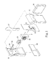
- Fig. 1 is an exploded perspective view of a DV camera with projector mechanism according to an embodiment of the present invention
- Fig. 2 is an assembled view of Fig. 1 ;
- Fig. 3 is a sectioned front view of Fig. 2 ;
- Fig. 1 and 2 are exploded and assembled perspective views, respectively, of a digital video (DV) camera with projector mechanism according to an embodiment of the present invention
- Fig. 3 is a sectioned front view of Fig. 2
- the DV camera with projector mechanism according to the present invention includes a DV camera 1 and a projector mechanism 2.
Landscapes
- Engineering & Computer Science (AREA)
- Multimedia (AREA)
- Signal Processing (AREA)
- Physics & Mathematics (AREA)
- General Physics & Mathematics (AREA)
- Projection Apparatus (AREA)
- Studio Devices (AREA)
Abstract
Description
- The present invention relates to a digital video (DV) camera, and more particularly to a DV camera with projector mechanism that allows dynamic pictures and still images shot using the DV camera to be directly output via the projector mechanism for viewing without the need of image processing.
- Generally, a conventional digital video (DV) camera can internally process and convert dynamic pictures or still images shot using the DV camera, and then stores the processed and converted pictures or images on a memory, so that a user may review the shot dynamic pictures or still images at a display on the DV camera. When it is desired to play back the shot dynamic pictures or still images on an external screen, the dynamic pictures or still images stored in the DV camera must be transmitted via a cable to a computer, and the computer is driven by related software to edit the dynamic pictures or still images using specific programs, so that the dynamic pictures or still images are converted into specific files and subjected to related processes, and finally recorded on a compact disk (CD). Then, the dynamic pictures or still images recorded on the compact disk are read using a CD ROM, and then played back on an external screen linked to the CD ROM.
- While the dynamic pictures or still images shot using the DV camera can be played back on an external screen via a computer, the computer must first process the dynamic pictures or still images using related driver and editing software. That is, the user could not play back the shot dynamic pictures or still images in real time, and a lot of time is wasted in image processing via complicated procedures.
- A primary object of the present invention is to provide a DV camera with projector mechanism, so that dynamic pictures and still images shot using the DV camera can be directly output for viewing via a projector mechanism associated with the DV camera to save the time required for image processing.
- To achieve the above and other objects, the DV camera with projector mechanism according to the present invention includes a processing unit provided in an enclosure, and a shooting unit, an audio input/output unit, a storage unit, a display unit, an operating interface unit, and a power supply unit mounted to the enclosure and electrically connected to the processing unit; and a projector mechanism being arranged in the enclosure at a suitable position and electrically connected to the processing unit of the DV camera.
- The structure and the technical means adopted by the present invention to achieve the above and other objects can be best understood by referring to the following detailed description of the preferred embodiments and the accompanying drawings, wherein
-
Fig. 1 is an exploded perspective view of a DV camera with projector mechanism according to an embodiment of the present invention; -
Fig. 2 is an assembled view ofFig. 1 ; -
Fig. 3 is a sectioned front view ofFig. 2 ; -
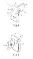
Fig. 4 shows the use of the DV camera of the present invention for shooting pictures; -
Fig. 5 shows the use of the DV camera of the present invention to compose a shot or review images; and -
Fig. 6 shows the use of the DV camera of the present invention to play back shot images via a projector mechanism associated with the DV camera. - Please refer to
Fig. 1 and2 that are exploded and assembled perspective views, respectively, of a digital video (DV) camera with projector mechanism according to an embodiment of the present invention, and toFig. 3 that is a sectioned front view ofFig. 2 . As shown, the DV camera with projector mechanism according to the present invention includes aDV camera 1 and aprojector mechanism 2. - The
DV camera 1 has anenclosure 11, in which aprocessing unit 12 is provided. At least ashooting unit 13, an audio input/output unit 14, astorage unit 15, adisplay unit 16, anoperating interface unit 17, and apower supply unit 18 are mounted to theenclosure 11 to electrically connect to theprocessing unit 12. Theshooting unit 13 may be located at a front side of theenclosure 11, the audio input/output unit 14 may be arranged on theenclosure 11 close to theshooting unit 13, thestorage unit 15 may include an internal memory and/or an external memory card, thedisplay unit 16 may be provided to one lateral side of theenclosure 11, theoperating interface unit 17 may be arranged at a rear side of theenclosure 11 or associated with thedisplay unit 16 to form a touch panel, and thepower supply unit 18 may be provided to the other lateral side of theenclosure 11. Alternatively, anauxiliary light source 19 may be arranged on theenclosure 11 close to theshooting unit 13 to electrically connect to theprocessing unit 12. It is understood theshooting unit 13, the audio input/output unit 14, thestorage unit 15, thedisplay unit 16, theoperating interface unit 17, and thepower supply unit 18 may be otherwise arranged on theenclosure 11 at different positions according to actual need. - The
projector mechanism 2 is electrically connected to theprocessing unit 12 of theDV camera 1, and is arranged in theenclosure 11 at a suitable place, such as the front side, the rear side, or one lateral side of theenclosure 11, depending on actual need. Theprojector mechanism 2 may include animage adjusting unit 21. -
Figs. 4, 5 and6 show the use of the DV camera with projector mechanism according to the present invention to shoot pictures via theshooting unit 13, to compose a shot or review shot images via thedisplay unit 16, and to play back images via theprojector mechanism 2, respectively. As shown, to use the present invention, a user may use theoperating interface unit 17 to set theDV camera 1 to a desired shooting mode and other related settings, and then use theshooting unit 13 and the audio input/output unit 14 to shoot dynamic pictures or still images. Thereafter, related processing and conversion are carried out by theprocessing unit 12, so that the dynamic pictures or still images shot using theDV camera 1 are converted into a required read format and stored on thestorage unit 15. At this point, the user may control theoperating interface unit 17 to output the dynamic pictures or still images at thedisplay unit 16 for reviewing. Alternatively, the user may control theoperating interface unit 17 to output the dynamic pictures or still images via theprojector mechanism 2, so that the dynamic pictures or still images are projected onto an external screen for viewing. Meanwhile, a corresponding sound effect may be output via the audio input/output unit 14. The user may also use theimage adjusting unit 21 to focus the images projected using theprojector mechanism 2. Therefore, theDV camera 1 cooperates with theprojector mechanism 2 to provide the functions of directly playing back dynamic pictures or still images without the need of a computer and saving the time for image processing. - The present invention has been described with a preferred embodiment thereof and it is understood that many changes and modifications in the described embodiment can be carried out without departing from the scope and the spirit of the invention that is intended to be limited only by the appended claims.
Claims (10)
- A digital video (DV) camera with projector mechanism, comprising:a DV camera having an enclosure, a processing unit provided in the enclosure, and a shooting unit, an audio input/output unit, a storage unit, a display unit, an operating interface unit, and a power supply unit mounted to the enclosure and electrically connected to the processing unit; anda projector mechanism being mounted in the enclosure at a predetermined position and electrically connected to the processing unit of the DV camera.
- The DV camera with projector mechanism as claimed in claim 1, wherein the shooting unit is located at a front side of the enclosure.
- The DV camera with projector mechanism as claimed in claim 1, wherein the audio input/output unit is arranged on the enclosure close to the shooting unit.
- The DV camera with projector mechanism as claimed in claim 1, wherein the storage unit is selected from the group consisting of an internal memory, an external memory card, and a combination thereor.
- The DV camera with projector mechanism as claimed in claim 1, wherein the display unit is arranged to one lateral side of the enclosure.
- The DV camera with projector mechanism as claimed in claim 1, wherein the operating interface unit is arranged at a rear side of the enclosure.
- The DV camera with projector mechanism as claimed in claim 1, wherein the operating interface unit is associated with the display unit.
- The DV camera with projector mechanism as claimed in claim 1, wherein the power supply unit is located at one lateral side of the enclosure.
- The DV camera with projector mechanism as claimed in claim 1, wherein the projector mechanism is arranged on the enclosure at a position selected from the group consisting of a front side, a rear side, and a lateral side of the enclosure.
- The DV camera with projector mechanism as claimed in claim 1, wherein the projector mechanism includes an image adjusting unit.
Priority Applications (1)
| Application Number | Priority Date | Filing Date | Title |
|---|---|---|---|
| EP08157814A EP2131571A1 (en) | 2008-06-06 | 2008-06-06 | Digital video camera with projector mechanism |
Applications Claiming Priority (1)
| Application Number | Priority Date | Filing Date | Title |
|---|---|---|---|
| EP08157814A EP2131571A1 (en) | 2008-06-06 | 2008-06-06 | Digital video camera with projector mechanism |
Publications (1)
| Publication Number | Publication Date |
|---|---|
| EP2131571A1 true EP2131571A1 (en) | 2009-12-09 |
Family
ID=39577762
Family Applications (1)
| Application Number | Title | Priority Date | Filing Date |
|---|---|---|---|
| EP08157814A Withdrawn EP2131571A1 (en) | 2008-06-06 | 2008-06-06 | Digital video camera with projector mechanism |
Country Status (1)
| Country | Link |
|---|---|
| EP (1) | EP2131571A1 (en) |
Citations (6)
| Publication number | Priority date | Publication date | Assignee | Title |
|---|---|---|---|---|
| EP0553700A1 (en) * | 1992-01-29 | 1993-08-04 | Deutsche Thomson-Brandt GmbH | Video camera, optionally operable as projector |
| US5258844A (en) * | 1990-07-13 | 1993-11-02 | Casio Computer Co., Ltd. | Video camera apparatus having an image projection function |
| US20060291851A1 (en) * | 2005-02-08 | 2006-12-28 | Nikon Corporation | Digital camera with projector and digital camera system |
| US20070063979A1 (en) * | 2005-09-19 | 2007-03-22 | Available For Licensing | Systems and methods to provide input/output for a portable data processing device |
| WO2008020340A1 (en) * | 2006-08-17 | 2008-02-21 | Sony Ericsson Mobile Communications Ab | Projector adaptation |
| US20080068495A1 (en) * | 2006-09-19 | 2008-03-20 | Gwenne Siron Bacani | Imajector |
-
2008
- 2008-06-06 EP EP08157814A patent/EP2131571A1/en not_active Withdrawn
Patent Citations (6)
| Publication number | Priority date | Publication date | Assignee | Title |
|---|---|---|---|---|
| US5258844A (en) * | 1990-07-13 | 1993-11-02 | Casio Computer Co., Ltd. | Video camera apparatus having an image projection function |
| EP0553700A1 (en) * | 1992-01-29 | 1993-08-04 | Deutsche Thomson-Brandt GmbH | Video camera, optionally operable as projector |
| US20060291851A1 (en) * | 2005-02-08 | 2006-12-28 | Nikon Corporation | Digital camera with projector and digital camera system |
| US20070063979A1 (en) * | 2005-09-19 | 2007-03-22 | Available For Licensing | Systems and methods to provide input/output for a portable data processing device |
| WO2008020340A1 (en) * | 2006-08-17 | 2008-02-21 | Sony Ericsson Mobile Communications Ab | Projector adaptation |
| US20080068495A1 (en) * | 2006-09-19 | 2008-03-20 | Gwenne Siron Bacani | Imajector |
Similar Documents
| Publication | Publication Date | Title |
|---|---|---|
| CN100539637C (en) | Imaging device | |
| US7884881B2 (en) | Image pickup apparatus with a display unit provided on a handle | |
| TWI432018B (en) | Viewfinder device, viewfinder device fixing adapter | |
| EP1785997A3 (en) | Digital audio recording/reproduction apparatus for recording and reproducing still image and video and method of providing user interface therein | |
| JPH11305335A (en) | Presentation system | |
| JP2004222236A (en) | Imaging device, image editing method and program | |
| JP2008236035A (en) | Image display device | |
| JP2006042170A (en) | Reproducing apparatus, camera and sound volume control method of reproducing apparatus | |
| JP2006279757A (en) | Imaging apparatus, audio recording method, and program | |
| CN207491129U (en) | A kind of intelligent interaction projecting apparatus | |
| CN106375811A (en) | Program play control method and device | |
| EP2131571A1 (en) | Digital video camera with projector mechanism | |
| US20090244322A1 (en) | Digital video camera with projector mechanism | |
| CN102420961B (en) | Projection arrangement, method for controlling projection | |
| JP2008014963A (en) | Projection type display device and control method thereof | |
| JP2005071192A (en) | Projection display apparatus, program, and recording medium | |
| CN112312002A (en) | High-definition course recording and displaying system | |
| US7982780B2 (en) | Photographing apparatus having multiple control button sets and displays and method of displaying image | |
| JP2005286718A (en) | IMAGING DEVICE, VOICE INPUT CONTROL METHOD AND PROGRAM USED FOR THIS IMAGING DEVICE | |
| JP2018067885A (en) | Imaging device and imaging method, and program | |
| JP4535089B2 (en) | Imaging apparatus, image processing method, and program | |
| CN201060361Y (en) | Projection/photographic device | |
| US20080284894A1 (en) | Device capable of image capturing and image projection | |
| JP2006197500A (en) | Imaging apparatus, image processing method, and program | |
| JP2005229370A (en) | Imaging apparatus, image processing method, and program |
Legal Events
| Date | Code | Title | Description |
|---|---|---|---|
| PUAI | Public reference made under article 153(3) epc to a published international application that has entered the european phase |
Free format text: ORIGINAL CODE: 0009012 |
|
| AK | Designated contracting states |
Kind code of ref document: A1 Designated state(s): AT BE BG CH CY CZ DE DK EE ES FI FR GB GR HR HU IE IS IT LI LT LU LV MC MT NL NO PL PT RO SE SI SK TR |
|
| AX | Request for extension of the european patent |
Extension state: AL BA MK RS |
|
| 17P | Request for examination filed |
Effective date: 20100609 |
|
| 17Q | First examination report despatched |
Effective date: 20100702 |
|
| AKX | Designation fees paid |
Designated state(s): AT BE BG CH CY CZ DE DK EE ES FI FR GB GR HR HU IE IS IT LI LT LU LV MC MT NL NO PL PT RO SE SI SK TR |
|
| STAA | Information on the status of an ep patent application or granted ep patent |
Free format text: STATUS: THE APPLICATION IS DEEMED TO BE WITHDRAWN |
|
| 18D | Application deemed to be withdrawn |
Effective date: 20101113 |