EP2131533A1 - Method and apparatus for packet reordering during a handover of a mobile station - Google Patents
Method and apparatus for packet reordering during a handover of a mobile station Download PDFInfo
- Publication number
- EP2131533A1 EP2131533A1 EP20090153815 EP09153815A EP2131533A1 EP 2131533 A1 EP2131533 A1 EP 2131533A1 EP 20090153815 EP20090153815 EP 20090153815 EP 09153815 A EP09153815 A EP 09153815A EP 2131533 A1 EP2131533 A1 EP 2131533A1
- Authority
- EP
- European Patent Office
- Prior art keywords
- base station
- enb
- packet
- target base
- packet data
- Prior art date
- Legal status (The legal status is an assumption and is not a legal conclusion. Google has not performed a legal analysis and makes no representation as to the accuracy of the status listed.)
- Granted
Links
Images



Classifications
-
- H—ELECTRICITY
- H04—ELECTRIC COMMUNICATION TECHNIQUE
- H04W—WIRELESS COMMUNICATION NETWORKS
- H04W36/00—Hand-off or reselection arrangements
- H04W36/02—Buffering or recovering information during reselection ; Modification of the traffic flow during hand-off
-
- H—ELECTRICITY
- H04—ELECTRIC COMMUNICATION TECHNIQUE
- H04L—TRANSMISSION OF DIGITAL INFORMATION, e.g. TELEGRAPHIC COMMUNICATION
- H04L47/00—Traffic control in data switching networks
- H04L47/10—Flow control; Congestion control
- H04L47/34—Flow control; Congestion control ensuring sequence integrity, e.g. using sequence numbers
-
- H—ELECTRICITY
- H04—ELECTRIC COMMUNICATION TECHNIQUE
- H04L—TRANSMISSION OF DIGITAL INFORMATION, e.g. TELEGRAPHIC COMMUNICATION
- H04L49/00—Packet switching elements
- H04L49/90—Buffering arrangements
Definitions
- the header part includes a GTP-U header I and an Extension header II.
- each tunnel ID (TE-ID) 10 formed of 32 bits for each service is assigned to the GTP-U header I.
- a serial number 11 is assigned to the packet, according to the GTP-U protocol.
- the target base station (T-eNB) requests and establishes a GTP-U TEID: ⁇ 2 ⁇ between with the source base station (S-eNB).
- the gateway starts transmission successively from the "20th" packet of TEID: ⁇ 1 ⁇ to the target base station (T-eNB), using TEID: ⁇ 3 ⁇ [refer to (4) in FIG. 5 ].
- the gateway transmits the data concerned to the target base station (T-eNB) by setting the uppermost bit in the version field of the GTP-U header to [1].
- the target base station (T-eNB) understands that the top packet from the gateway (GW) has the GTP-U serial number "20"
- the target base station (T-eNB) transmits to the mobile unit (UE) the packets received from the source base station (S-eNB) having the GTP-U serial numbers "10" to "19". Thereafter, the target base station (T-eNB) transmits the packets received from the gateway (GW) having the GTP-U serial numbers "20" and after.
- the top packet is obtained in the target base station (T-eNB), it is possible to decide the packet order from the received packet itself, and the packet can be transmitted to the user equipment (UE) together with order information.
- T-eNB target base station
- UE user equipment
Landscapes
- Engineering & Computer Science (AREA)
- Computer Networks & Wireless Communication (AREA)
- Signal Processing (AREA)
- Computer Security & Cryptography (AREA)
- Mobile Radio Communication Systems (AREA)
Abstract
Description
- The present invention relates to a mobile communication system in which a user equipment receives packet data from a gateway through a base station.
- Among the nodes of a mobile communication network (UTRAN: Universal Mobile Telecommunication Terrestrial Radio Access Network) specified by the 3GPP (3rd Generation Partnership Project), a user equipment (UE), which is also called as a mobile station, receives packet data from a gateway (GW) through a base station.
- A handover (HO) between base stations is performed when the user equipment (UE) moves the area position thereof from an accommodating base station (movement-source base station, written as Source evolved Node B: S-eNB) presently receiving packet data to a neighboring base station (movement-target base station, written as Target evolved Node B: T-eNB). Here, as to the reception of downlink packet data from the gateway (GW), the continuity of the received data is desired for the user equipment (UE).
-
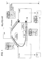
FIG. 1 is a diagram illustrating an exemplary configuration of handover (HO) between base stations in the UTRAN of the mobile communication system. - There is assumed a case that a user equipment (UE) receiving data from a gateway (GW) through a source base station (S-eNB) is presently located in the area of a target base station (T-eNB), accompanying a handover from a source base station (S-eNB).
- In such the case, in regard to a packet data in the gateway (GW), the user equipment (UE) is to receive the data through the target base station (T-eNB) as a data transferred from the source base station (S-eNB) to the target base station (T-eNB) and a data transmitted directly from the gateway (GW) to the target base station (T-eNB).
- Here, according to the configuration illustrated in
FIG. 1 , the user equipment (UE) can form reception data in correct order (i.e. sequential), through packet data order arrangement using a packet data convergence protocol (PDCP) between with the gateway (GW). - More specifically, using sequence numbers in the PDCP between the gateway (GW) of a data transmission source and the receiving user equipment (UE), PDCP reordering (sequence reconfiguration) processing is performed in the user equipment (UE). By this, it is possible to guarantee the order of the received packets, even if the packet order is reversed at the time of the output from the gateway (GW) or caused by the base station (eNB) and the IP network located on the half way.
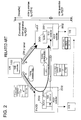
- In contrast, according to the configuration of 3GPP LTE (Long Term Evolution) proposed by the standardization project (3GPP: the 3rd Generation Partnership Project) for the third generation mobile communication system, UTRAN in the mobile communication system illustrated in
FIG. 1 becomes as illustrated inFIG. 2 . - Namely, the PDCP function having been installed in the gateway (GW) is moved to a base station (eNB). As a result, PDCP is to be exchanged between the base station (eNB) and the user equipment (UE). In this case, there is no protocol for guaranteeing packet order end-to-end between the gateway (GW) and the user equipment (UE).
- Therefore, it is no more possible to guarantee the order of the received packets between the gateway (GW) and the user equipment (UE).
- To describe in more detail, in the IP network, any IP packet having a predetermined maximum transfer unit size (hereafter referred to as MTU: Maximum Transfer Unit) or larger is divided into packets by the MTU length.
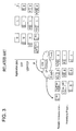
-
FIG. 3 is a diagram illustrating an example of packet transfer in the above IP network. InFIG. 3 , no mechanism is provided to distinguish the order in case of IP packets each having the MTU length or smaller. As a result, packets may possibly arrive after the packet transfer order is reversed due to a large delay through a changed route etc. - In the above case, although packets "0-1" and "0-2" divided by the MTU size can be assembled on the receiving side, it is not possible to assemble
undivided packets - Therefore, in the IP network transfer, it is not possible to restore to a correct order when the order has been reversed due to the route change etc.
- As a result, in the configuration of 3GPP LTE (Long Term Evolution) as illustrated in
FIG. 2 , a reverse data order may possibly occur in the cases of both data transfer from the source base station (S-eNB) to the target base station (T-eNB) and direct transmission from the gateway (GW) to the target base station (T-eNB) due to the route change. In the above cases, the continuity of data reception may not be obtained in the user equipment (UE). - For example, in the
documents
[Document 1] TS36.300 v8.3.0 (Chapter 19)
[Document 2] TS36.413 v2.0.0 (Chapters 8.2.1, 9.1 and 9.2) - Accordingly, the objective of the present invention is to provide a mobile communication system enabling data reception in correct order, with regard to a reversed data order caused by a route change in data transfer from a source base station (S-eNB) to a target base station (T-eNB) and in direct transmission from a gateway (GW) to a target base station (T-eNB).
- In a mobile communication system receiving packet data from a gateway (GW) by a user equipment (UE) through a base station (eNB), at the time of handover processing performed accompanying a movement of the user equipment (UE), receiving sequential packet data from the gateway (GW), from a source base station (S-eNB) to a target base station (T-eNB), when the source base station (S-eNB) transfers to the target base station (T-eNB) a packet data having been received from the gateway (GW) but not transmitted yet to the user equipment (UE), the source base station (S-eNB) assigns transfer start information to a header in the top packet of the untransmitted packet data.
- Further, the above gateway (GW) assigns transfer start information to a header in the top packet of the packet data not transmitted yet via the above source base station (S-eNB), among the sequential packet data destined to the user equipment (UE), so as to directly transmit to the above target base station (T-eNB). As a typical example, a GTP (General Packet Radio Services Tunneling Protocol)-U protocol sequence number for use between the gateway (GW) and the source base station (S-eNB) and a GTP-U protocol sequence number for use between the gateway (GW) and the target base station (T-eNB) are used, so as to be related with each other.
- At the same time, a transfer start information bit is newly given to the GTP-U header between the gateway (GW) and the source base station (S-eNB), as well as in the GTP-U header between the source base station (S-eNB) and the target base station (T-eNB), so as to guarantee the order.
- Further, even in case the top packet is discarded, to distinguish an intermediate packet and a last packet, a sequence number of the packet of which transmission is to start is assigned to each GTP-U header on the basis of the transmission packet.
- The object and advantages of the invention will be realized and attained by means of the elements and combinations particularly pointed out in the claims.
- It is to be understood that both the foregoing general description and the following detailed description are exemplary and explanatory and are not restrictive of the invention, as claimed.
-
-
FIG. 1 is a diagram illustrating an exemplary configuration of handover (HO) between base stations in the UTRAN of the mobile communication system; -
FIG. 2 illustrates UTRAN of the mobile communication system in 3GPP LTE (Long Term Evolution); -
FIG. 3 is a diagram illustrating an example of packet transfer in the IP network; -
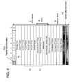
FIG. 4 is a diagram illustrating an exemplary configuration of an embodiment of a header part in a cell format according to the GTP-U protocol specified by the 3GPP, to be used between the gateway and the source base station (and the target base station); -
FIG. 5 is a diagram illustrating a typical example of data flow in which the above-mentioned mechanism is applied in the LTE UTRAN configuration illustrated inFig. 2 ; -
FIG. 6 is a flowchart illustrating a processing flow corresponding toFig. 5 ; -
FIG. 7 is a detailed processing flow of requesting and establishing the tunnel ID in the target base station (T-eNB); -
FIG. 8 is a reception processing flow in the target base station (T-eNB) in regard to the packets transmitted from the source base station (S-eNB), corresponding to step S16 of the sequence flow illustrated inFIG. 6 ; -
FIG. 9 is a flowchart corresponding to the step S16 in the sequence flow illustrated inFIG. 6 ; -
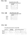
FIG. 10A illustrates a GTP-SN (serial number) management memory relative to the source base station (S-eNB); -
FIG. 10B illustrates a GTP-SN management memory relative to the target base station (T-eNB); -
FIG. 10C shows an example of a memory for relating TEIDs provided incontroller 301 of the target base station (T-eNB); -
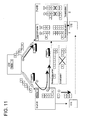
FIG. 11 is a diagram illustrating a packet data flow in the above quasi-normal case; -
FIG. 12 is a diagram illustrating a packet data flow in the second embodiment; -
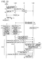
FIG. 13 is a flow diagram illustrating the processing flow corresponding toFIG. 12 . - The preferred embodiments are described hereinafter referring to the charts and drawings.
- As an embodiment, in the LTE UTRAN configuration illustrated in the above
FIG. 2 , there is provided a mechanism taking the following conditions into consideration, so that the reverse of packet order in the data reception does not occur. - In regard to data which are to be transmitted from a gateway (GW), an upper-level unit, and received in a target base station (T-eNB) in the event of handover (HO), two routes (A and B illustrated in
FIG. 2 ) exist: a route through which the data is received via a source base station (S-eNB) ; and a route through which the data is received directly from the gateway (GW). - Here, according to the 3GPP (the 3rd Generation Partnership Project) LTE, a PDCP control function is shifted to the base station (eNB) side. Further, the GTP-U protocol is applied between the gateway (GW) and the source base station (S-eNB), and a sequence number (transfer order information) is assigned to a transmission packet.
- Therefore, when looked from the target base station (T-eNB), the received sequence number used between the gateway (GW) and the source base station (S-eNB) according to the GTP-U protocol of the 3GPP is not limited to the original sequence number assigned by the gateway (GW).
- Also, in the target base station (T-eNB), it is not certain whether data respectively received from the gateway (GW) and the source base station (S-eNB) for the first time after the occurrence of the handover are truly top packet data respectively output from the source base station (S-eNB) on the transmission side and the gateway (GW), depending on a network condition.
- Therefore, to arrange the order from the top data, it is desired to inform of a data transmitted first from the transmission side. At the same time, in regard to a data transferred from the source base station (S-eNB), because a last packet data is not known also, it is desired to inform the target base station (T-eNB), as the case may be.
- Taking such the conditions into consideration, according to the present embodiment, a mechanism to distinguish the continuity of the order is provided. To distinguish the above order continuity, there is provided a mechanism to enable the target base station (T-eNB) to distinguish a top packet of the data which the source base station (S-eNB) has started transmitting to the target base station (T-eNB), and a last transmission packet.
-
FIG. 4 is a diagram illustrating an exemplary configuration of an embodiment of a header part in a cell format according to the GTP-U protocol specified by the 3GPP (3rd Generation Partnership Project), to be used between the gateway (GW) and the source base station (S-eNB) (and the target base station (T-eNB)). - The header part includes a GTP-U header I and an Extension header II. According to the GTP-U protocol, each tunnel ID (TE-ID) 10 formed of 32 bits for each service is assigned to the GTP-U header I. Further, a
serial number 11 is assigned to the packet, according to the GTP-U protocol. - According to a first embodiment, an upper one bit in a 3-bit field (the 5th-7th bits, only in use to identify either the
version 0 or 1) 12 in a version field of the GTP-U header I is used, as transfer startinformation 12A. - When transmitting data to the target base station (T-eNB), the gateway (GW) makes effective (sets "1" on the bit of) the transfer start
information 12A in regard to a first data only. By this, it is possible to show that the data concerned is a first packet data for the transmission from the gateway (GW) to the target base station (T-eNB). - Similarly, when transferring to the target base station (T-eNB) data being already buffered or in the middle of buffering in the source base station (S-eNB), the source base station (S-eNB) makes effective the transfer start
information 12A in a data to be transmitted first from the source base station (S-eNB) to the target base station (T-eNB), to indicate the data concerned is a first packet data for transmission. - As a use condition of the header part in the cell format according to the above embodiment, the following aspect is employed.
- On the transmission side,
sequence number 11 indicative of a transmission order is assigned. In the gateway (GW) i.e. the transmission side, if sequence numbers 11 continue to be assigned sequentially and consecutively under the identical tunnel ID (TE-ID) 10 even when the base station (eNB) is changed, the target base station (T-eNB) can arrange the order. - However, because the decision of use of tunnel ID (TE-ID) 10 can freely be made by the reception side, tunnel IDs (TE-IDs) 10 differ between the gateway (GW) and the source base station (S-eNB), between the gateway (GW) and the target base station (T-eNB), and between the source base station (S-eNB) and the target base station (T-eNB), respectively.
- To cope with the above-mentioned problem, the following configuration is applied so as to make
sequence numbers 11 in the GTP-U header I sequentially consecutive when looked from the target base station (T-eNB), by relating the changed tunnel ID (TE-ID) 10 even if tunnel ID (TE-ID) 10 is changed. - When a base station (eNB) is changed due to a handover, the following mechanism is provided in the gateway (GW). Namely, in regard to sequence
number 11 having been requested from the source base station (S-eNB) and assigned to one certain tunnel ID (TE-ID) 10, the gateway (GW) changes tunnel ID (TE-ID) 10 to a tunnel ID (TE-ID) 10 requested from the target base station (T-eNB), and successively assigns sequence numbers following theabove sequence number 11. - At the source base station (S-eNB), in regard to each untransmitted data destined to the user equipment (UE), having tunnel ID (TE-ID) 10 which has been in communication with the gateway (GW) at the time of the handover, is changed to have tunnel ID (TE-ID) 10 being requested from the target base station (T-eNB). Subsequently, the source base station (S-eNB) transmits the above data to the target base station (T-eNB) without changing
sequence number 11. - At the target base station (T-eNB), each tunnel ID (TE-ID) 10 requested to the gateway (GW) and the source base station (S-eNB) is managed in a unified manner. The target base station (T-eNB) buffers data received from the gateway (GW), and transmits data, received from the source base station (S-eNB), first to the user equipment (UE).
- Thereafter, the target base station (T-eNB) successively transmits the data received from the gateway (GW) to the user equipment (UE). At this time, using the PDCP function provided in the target base station (T-eNB), each sequence number, which is transfer order information indicating the order, is newly assigned sequentially and correspondingly to GTP-
U sequence number 11. -
FIG. 5 is a diagram illustrating a typical example of data flow in which the above-mentioned mechanism is applied in the LTE UTRAN configuration illustrated in the aboveFig. 2 . - Here, in the UTRAN configuration of LTE illustrated in
FIG. 2 , the gateway (GW) includes aTEID controller 100. Also, the source base station (S-eNB) and the target base station (T-eNB) includebuffers TEID controllers PDCP controllers - In
FIG. 5 , as a tunnel ID (TEID) between the gateway (GW) and the source base station (S-eNB), {1} is set by a request from the source base station (S-eNB). - In
FIG. 5 , packet data having GTP-U sequence numbers "1" to "19" are transmitted from the gateway (GW) to the source base station (S-eNB). Among the above data, data whose transmission from the source base station (S-eNB) to the user equipment (UE) is completed are GTP-U sequence numbers "1" up to "9" under TEID: {1} [refer to (1) inFIG. 5 ]. - When handover (HO) processing is started at the above time point caused by the movement of the user equipment (UE), the target base station (T-eNB) requests and establishes a GTP-U TEID: {2} between with the source base station (S-eNB).
- Then, the source base station (S-eNB) pairs TEID: {1} with {2}, so as to store into a table of a
TEID controller 201 by relating each other. Further, the target base station (T-eNB) requests and establishes a GTP-U TEID: {3} between with the gateway (GW). - By this, the gateway (GW) pairs the TEID: {1} with {3}, so as to store into a table of
TEID controller 100 by relating each other. Also, the target base station (T-eNB) pairs the TEID: {2} with {3}, so as to store into a table ofTEID controller 301 by relating each other. - Referring back to
FIG. 5 , when the handover (HO) is started, the source base station (S-eNB) starts transmission to the target base station (T-eNB) from a packet having a serial number "10" of TEID: {1}, using TEID: {2} [refer to (2) inFIG. 5 ]. - At that time, since the serial number "10" is a first data for transmission, the source base station (S-eNB) transmits the data concerned is to the target base station (T-eNB) by setting the uppermost bit in the version field of the GTP-U header to [1].
- At the same time, the gateway (GW) starts transmission successively from the "20th" packet of TEID: {1} to the target base station (T-eNB), using TEID: {3} [refer to (4) in
FIG. 5 ]. - At that time, since the "20th" packet is a first data for transmission, the gateway (GW) transmits the data concerned to the target base station (T-eNB) by setting the uppermost bit in the version field of the GTP-U header to [1].
- Then, the target base station (T-eNB) decides that the data having the GTP-U serial number "10" with the top flag of TEID: {2} assigned thereto is a top data from the source base station (S-eNB). Also, the target base station (T-eNB) decides that the data having the GTP-U serial number "20" with the top flag of TEID: {3} assigned thereto is a top data from the gateway (GW).
- Because the target base station (T-eNB) understands that the top packet from the gateway (GW) has the GTP-U serial number "20", the target base station (T-eNB) transmits to the mobile unit (UE) the packets received from the source base station (S-eNB) having the GTP-U serial numbers "10" to "19". Thereafter, the target base station (T-eNB) transmits the packets received from the gateway (GW) having the GTP-U serial numbers "20" and after.
-
FIG. 6 is a flowchart illustrating a processing flow corresponding toFig. 5 . - The source base station (S-eNB) requests the gateway (GW) to set a GTP-U ID (TE-ID) {1} between with the gateway (GW) (step S1).
- By this,
TEID controller 100 in the gateway (GW) sets the above tunnel ID (TE-ID) {1}. - Here, as illustrated in
FIGS. 10A and 10B ,TEID controller 100 in the gateway (GW) provides a GTP-SN (serial number) management memory relative to the source base station (S-eNB) (FIG. 10A ) and a GTP-SN management memory relative to the target base station (T-eNB) (FIG. 10B ). - In each GTP-SN (serial number) management memory, there is registered a GTP serial number having been assigned and set before, on the basis of each tunnel ID (TE-ID).
- The above GTP-SN (serial number) management memories illustrated in
FIGS. 10A, 10B are also provided inTEID controller 201 of the source base station (S-eNB). Here, in the source base station (S-eNB), the above memories include a GTP-SN management memory relative to the gateway (GW) and a GTP-SN management memory relative to the target base station (T-eNB). -
FIG. 10C shows an example of a memory for relating TEIDs provided incontroller 301 of the target base station (T-eNB). Corresponding to the related TEID, a top TEID relative to the base station (S-eNB) and a top TEID relative to the gateway (GW) are registered when transfer start information is decided. Further,PDCP controller 302 records a serial number assigned at the time of the packet transfer to the user equipment (UE). - To describe referring back to
FIG. 6 , corresponding to the tunnel ID (TE-ID) {1}, the gateway (GW) assigns sequence number 11 (refer toFIG. 4 ) to a packet GTP header I by the GTP-U protocol, so as to store into the GTP-SN management memory illustrated inFIG. 10A . Also, the gateway (GW) transmits the packet having sequence number 11 (refer toFIG. 4 ) assigned thereto to the source base station (S-eNB) (step S2). - Here, the packet having the sequence number assigned by the GTP-U protocol relative to the tunnel ID (TE-ID) {1} is transmitted to the source base station (S-eNB) (step S2).
- Accordingly, the source base station (S-eNB) transfers the packet, transmitted from the gateway (GW), to the user equipment (UE) being presently situated in the area of the source base station (S-eNB) (step S3).
- Thereafter, the user equipment (UE) moves, and handover processing is started (step S4). It is assumed that, before the start of the handover processing, packets having sequence numbers "1" to "9" have been transmitted from the source base station (S-eNB) to the user equipment (UE).
- A notification of handover is informed from the source base station (S-eNB) to the gateway (GW) (step S6).
- Then, before the gateway (GW) recognizes the handover of the user equipment (UE) (step S8), packets having consecutive sequence numbers SN=10 to 19 are transmitted from the gateway (GW) to the source base station (S-eNB) by the GTP-U protocol (steps S5, S7).
- According to the handover of the user equipment (UE), the target base station (T-eNB) notifies the source base station (S-eNB) and the gateway (GW) of the requests of tunnel IDs (TE-IDs) {2}, {3}, respectively, so as to establish (steps S9, S10).
- On receiving the request notifications of the above tunnel IDs (TE-IDs) {2}, {3}, the gateway (GW) and the source base station (S-eNB) relate the above tunnel IDs (TE-IDs) with the existing tunnel ID (TE-ID) {1} (steps S11, S12).
- The gateway (GW) relates the tunnel ID (TE-ID) {1} with the tunnel ID (TE-ID) {3} of which the request has been notified (step S11). Also, the source base station (S-eNB) relates the tunnel ID (TE-ID) {1} with the tunnel ID (TE-ID) {2} of which the request has been notified (step S12).
-
FIG. 7 is a detailed processing flow of requesting and establishing the tunnel ID in the target base station (T-eNB). - In
FIG. 7 , the target base station (T-eNB) decides the existence or non-existence of a handover (process P1), and if the handover exists (Yes in process P1), the target base station (T-eNB) establishes the tunnel ID (TE-ID) {2} between with the source base station (S-eNB), and also establishes the tunnel ID (TE-ID) {3} between with the gateway (GW) (process P2). - Next, the target base station (T-eNB) stores the other related TEID into each TEID memory area provided in the memory of
TEID controller 302 of the target base station (T-eNB), as illustrated inFIG. 10C . - As such, the target base station (T-eNB) relates the TEID {2} with the TEID {3} (process P3).
- Referring back to the flow illustrated in
FIG. 6 , as transfer start (top) information, the gateway (GW) sets the bit to [1], illustrated as 12A inFIG. 4 , in a packet having a serial number SN=20, among the packet data destined to the target base station (T-eNB) (step S14). - Similarly, the source base station (S-eNB) assigns top information to the packet having a serial number SN=10, among the packet data not transmitted yet to the user equipment (UE) (step S15).
- Further, the source base station (S-eNB) transmits the packet having the serial number SN=10 and consecutive packet data having serial numbers SN=11 to 19 to the target base station (T-eNB), using TEID {2} (step S15A).
- Similarly, the gateway (GW) further transmits the packet having the serial number SN=20 and consecutive packet data having serial number SN=21 and after, to the target base station (T-eNB), using the tunnel ID {3} (step S14A).
- Therefore, from the gateway (GW), the packet having the serial number SN=20 and top information assigned thereto and the packets having the consecutive serial numbers are transmitted under the tunnel ID (TE-ID) {3}. Similarly, from the source base station (S-eNB), the packets which have been received from the gateway (GW) but not transmitted yet to the user equipment (UE) (i.e. the packets having the serial numbers 10-19) are transmitted to the target base station (T-eNB).
- Now, in regard to the packets thus transmitted from the source base station (S-eNB) and the gateway (GW), the target base station (T-eNB) receives the above packets according to the reception flow illustrated in
FIGS. 8 and9 , so as to transfer to the user equipment (UE) (step S16). -
FIG. 8 is a reception processing flow in the target base station (T-eNB) in regard to the packets transmitted from the source base station (S-eNB), corresponding to step S16 of the sequence flow illustrated inFIG. 6 . - Using
TEID controller 301, the target base station (T-eNB) receives the packets having the tunnel ID {2} (GTP serial numbers 10-19) from the source base station (S-eNB) (process P20), and decides whether or not the top packet flag (12A inFIG. 4 ) indicates effective (process P21). - If the top packet flag is not effective (No in process P21), it is decided whether or not the packet has the next (consecutive) GTP serial number to the top packet having been received (for example, the packet B illustrated in step S15A of
FIG. 6 ) (process P22). - In process P22, if the packet has not the next (consecutive) GTP serial number (No in process P22), the packet concerned is made to stay in
buffer 300, instead of being transmitted (process P23). The reason for making the received packet stay inbuffer 300 is that, if the packet has no consecutive GTP serial number SN, there is a possible case of a missing transmission packet, a reverse reception order, or a packet transferred from the gateway (GW). - In process P22, if the packet has the next (consecutive) GTP serial number (Yes in process P22), the target base station (T-eNB) transmits the packet to the user equipment (UE), after making a PDCP serial number correspond to the GTP serial number by PDCP controller 302 (process P25).
- Further, if there is a packet (s) made to stay in
buffer 300 instead of being transmitted (Yes in process P23,26), the target base station (T-eNB) transmits the packet(s) concerned to the user equipment (UE), after making each PDCP serial number consecutively correspond (process P27). - In process P21, if the top flag of the received packet indicates effective (Yes in process P21), a GTP serial number assigned in the gateway (GW) by the GTP-U protocol and included in the top packet from the source base station (S-eNB) becomes known (process P24).
- Accordingly, the target base station (T-eNB) transmits the packet concerned to the user equipment (UE), after making a PDCP serial number correspond to the GTP serial number by PDCP controller 302 (process P25).
- Further, if there is any packet (s) having a consecutive GTP serial number and staying in buffer 300 (Yes in process P26), the target base station (T-eNB) transmits the packet(s) concerned to the user equipment (UE), after making each PDCP serial number correspond to each GTP serial number by
PDCP controller 302, similarly to process P25 (process P27). - Now, in regard to the packets transmitted from the gateway (GW), the target base station (T-eNB) performs reception processing according to a flowchart illustrated in
FIG. 9 . Here,FIG. 9 corresponds to step S16 in the sequence flow illustrated inFIG. 6 . - By
TEID controller 301, the target base station (T-eNB) receives each packet having a tunnel ID (TE-ID) {3} from the gateway (GW) (process P30), and checks whether or not the top packet flag (12A inFIG. 4 ) indicates effective, so as to decide whether or not the packet concerned is a top packet (process P31). - If the top packet flag is not effective (No in process P31), it is decided whether or not the packet has the next (consecutive) GTP serial number to the top packet having been received (for example, the packet b illustrated in step S14A of
FIG. 6 ) (process P22). - In process P32, if the packet has not the next (consecutive) GTP serial number (No in process P32), the packet concerned is made to stay in
buffer 300, instead of being transmitted (process P33). The reason for making the received packet stay inbuffer 300 is that, if the packet has no consecutive GTP serial number SN, there is a possible case of a missing transmission packet, a reverse reception order, or a packet transferred from the source base station (S-eNB). - In process P32, if the GTP serial number is the next (consecutive) GTP serial number (Yes in process P32), it is decided whether the entire packets from the source base station (S-eNB) have been transmitted to the user equipment (UE) (process P35).
- If the entire packets from the source base station (S-eNB) have not been transmitted yet (No in process P35), the packet received is made to stay, instead of being transmitted (process P33).
- On the other hand, if the entire packets from the source base station (S-eNB) have been transmitted to the user equipment (UE) (Yes in process P35), the target base station (T-eNB) transmits the packet of interest to the user equipment (UE), after making a PDCP serial number correspond by PDCP controller 302 (process P36).
- Further, if there is any packet(s) made to stay in
buffer 300 instead of being transmitted (Yes in process P37), the target base station (T-eNB) transmits the packet(s) concerned to the user equipment (UE), after making each PDCP serial number consecutively correspond (process P38). - In the foregoing process P31, if the top flag of the received packet indicates effective (Yes in process P31), a GTP serial number in the last packet from the source base station (S-eNB) becomes known from the GTP serial number assigned to the packet, having the effective top flag, in the gateway (GW) by the GTP-U protocol (process P34).
- Accordingly, the target base station (T-eNB) decides whether or not the entire packets from the source base station (S-eNB) have been transmitted to the user equipment (UE) (process P35).
- If the entire packets from the source base station (S-eNB) have not been transmitted yet (No in process P35), the packet received is made to stay, instead of being transmitted (process P33).
- If the entire packets from the source base station (S-eNB) have been transmitted to the user equipment (UE) (Yes in process P35), the target base station (T-eNB) transmits the packet of interest to the user equipment (UE), after making a PDCP serial number correspond by PDCP controller 302 (process P36).
- Further, if there is any packet(s) made to stay in
buffer 300 instead of being transmitted (Yes in process P37), the target base station (T-eNB) transmits the packet(s) concerned to the user equipment (UE), after making each PDCP serial number consecutively correspond by PDCP controller 302 (process P38). - According to the above-mentioned embodiment, when the target base station (T-eNB) receives the top data described above from the source base station (S-eNB), the target base station (T-eNB) transmits, to the user equipment (UE), entire packets having smaller numbers than the GTP-U sequence number in the top packet data from the gateway (GW) first.
- At that time,
PDCP controller 302 assigns PDCP sequence numbers successively from the top packet, so as to transmit to the user equipment (UE). Thereafter,PDCP controller 302 continues to transmit packets received from the gateway (GW), successively from the received top packet. - Here, because the top data from the gateway (GW) can be distinguished by means of the top flag, it is possible to distinguish the last data from the source base station (S-eNB) by comparing the sequence numbers assigned by the GTP-U protocol. Therefore, such an item as a flag indicating the last data is not needed.
- In the aforementioned manner, the user equipment (UE) can consecutively receive packets in correct order even at the time of the handover, without addition of a new packet and a control signal.
- Here, in regard to packet reception at the time of handover, the following case is assumed as a quasi-normal operation.
- When looking from the target base station (T-eNB), in case a middle packet among consecutive packet data from the source base station (S-eNB) arrives with delay caused by a network problem, it is possible to assume an unreceived sequence number if a top data from the source base station (S-eNB) can be distinguished.
- Further, if the top data from the gateway (GW) can be distinguished, it is possible to distinguish the number of packet data which are to be received from the source base station (S-eNB) and have not arrived yet. Namely, in regard to data to be transmitted to the user equipment (UE), if
PDCP controller 302 in the target base station (T-eNB) makes each PDCP sequence number correspond to each GTP-U protocol sequence number, and sequentially assigns each PDCP sequence number in such a manner as to skip the PDCP sequence number of an unreceived packet data, the data concerned can be transmitted to the user equipment (UE). - It is possible to transmit the packet data received with a delay to the user equipment (UE) by assigning the PDCP sequence number skipped before thereto, and by making the packet data of interest interrupted in the middle of the transmission.
- It is possible to cope with a case of the quasi-normal operation when there is a packet data received with a delay, as described above. However, when looking from the target base station (T-eNB), in case that an intermediate packet data from the source base station (S-eNB) is discarded caused by a network problem, the PDCP sequence number is left skipped.
- Therefore, in the user equipment (UE), if retransmission is decided to be necessary, retransmission control is to be performed by the upper-level layer.
-
FIG. 11 is a diagram illustrating a packet data flow in the above quasi-normal case, in which a reverse order pattern (I inFIG. 11 ) and a discard pattern (II inFIG. 11 ) are illustrated. As described above, when there is a reverse data order or a discarded packet, it is possible to transmit packets to the user equipment (UE) by skipping a PDCP sequence number to be assigned corresponding to the GTP-U protocol sequence number. - In contrast, if the top data is lost, undesirably, a state of no data transmission to the user equipment (UE) is continued, because of an increased time for waiting the top data (resulting from a loss decision by the expiration of a timer), and because of an unknown top data which makes it impossible to decide the number of an intermediate data from the top of the sequence and accordingly, to assign a PDCP sequence number to the intermediate data concerned.
- Due to the above reason, the timing to transmit data to the user equipment (UE) is delayed as a whole. As a second embodiment to solve the above-mentioned inconvenience, transfer
order information 13 is assigned as an option to an extension header II in the GTP-U header illustrated inFIG. 4 . -
FIG. 12 is a diagram illustrating a packet data flow in the second embodiment.FIG. 13 is a flow diagram illustrating the processing flow corresponding toFIG. 12 . - In
FIG. 12 , in each of the gateway (GW) and the target base station (T-eNB), there is formed a function of assigning the GTP-U sequence number of a transmitted packet to the entire data destined to the target base station (T-eNB). - In the header part illustrated in
FIG. 4 , the sequence number field of the GTP-U header I, a basic header, has already been used for agenuine sequence number 11. Therefore, the above function is realized by using an option field [16 bits] 13 in the extension header II. - Namely, when a sequence number (11 in
FIG. 4 ) assigned by the GTP protocol is identical to a sequence number (13 inFIG. 4 ) in the option field, the target base station (T-eNB) decides the packet to be a top packet. - In
FIG. 12 , the source base station (S-eNB) assigns the GTP-U sequence number [10] of the top packet among consecutive packets (having GTP-U sequence numbers [10]-[19]) to be transmitted to the target base station (T-eNB), to eachoption field 13 of the extension header II in the entire packets of transmission object. - Meanwhile, the gateway (GW) assigns the GTP-U sequence number [20] of the top packet among consecutive packets (having GTP-U sequence numbers [20]-[23]) to each
option field 13 of the extension header II in the entire packets of transmission object. - Among the packets transmitted from the source base station (S-eNB) to the target base station (T-eNB), when a plurality of packets including the top packet do not arrive, the target base station (T-eNB) can decide a packet, which is received first having the GTP-U sequence number [14], to be a fifth packet, by comparing with the sequence number [10] assigned to option
field 13, although the top packet having the GTP-U sequence number [10] has not arrived. - Accordingly, in
PDCP controller 302, it is possible to transmit to the user equipment (UE) by assigning a PDCP sequence number [5]. It is also possible to process data received from the gateway (GW) in a similar manner. - In the user equipment (UE), even though the PDCP sequence numbers are not received in regular order, there is no problem because an order arrangement function is provided as an inherent function.
- As such, according to the second embodiment, although the top packet is obtained in the target base station (T-eNB), it is possible to decide the packet order from the received packet itself, and the packet can be transmitted to the user equipment (UE) together with order information.
-
FIG. 13 is a processing flow corresponding toFIG. 12 . - In the comparison with the processing flow according to the first embodiment illustrated in
FIG. 6 , first, when assigning top information (by settingbit 12A inFIG. 4 to "1") to the top packet in steps S14 and S15, processing (S14B, S15B) to assign the GTP-U sequence number of the top packet to the entire consecutive packets including the top packet is added. - Corresponding to the above processing, to packets received by the target base station (T-eNB), the sequence number identical to the GTP-U sequence number of the top packet is assigned to option
field 13. - Other points are similar to the processing described in
FIG. 6 . - As having been described, even if the mounting of the PDCP function is shifted from the gateway (GW) to the base station (eNB) according to the 3GPP LTE, it is possible to guarantee the order between the gateway (GW) and the terminal. Further, it is possible to reduce a waiting time timer when data do not arrive in correct order, and accordingly, to reduce a total system delay time.
- All examples and conditional language recited herein are intended for pedagogical purposes to aid the reader in understanding the invention and the concepts contributed by the inventor to furthering the art, and are to be construed as being without limitation to such specifically recited examples and conditions, nor does the organization of such examples in the specification relate to a showing of the superiority and inferiority of the invention. Although the embodiment (s) of the present inventions have been described in detail, it should be understood that the various changes, substitutions, and alterations could be made hereto without departing from the spirit and scope of the invention.
Claims (8)
- A mobile communication system comprising an upper-level unit(GW); source and target base stations(S-eNB,T-eNB); and a user equipment (UE) to receive packet data from the upper-level unit(GW)via either of the source and target base stations(S-eNB,T-eNB), characterized in that,
at the time of handover processing performed accompanying a movement of the user equipment (UE) from the source base station (S-eNB) to the target base station (T-eNB),the source base station (S-eNB) transfers to the target base station(T-eNB), a part of packet data not yet transmitted to the user equipment (UE), among packet data received from the upper-level device(GW), and
when transferring the part of packet data, the source base station(S-eNB)assigns transfer start information, indicating a start of transfer, to a header in a top packet of the untransmitted packet data,
the upper-level unit(GW) assigns the transfer start information to the header in the top packet of the packet data to be directly transmitted to the target base station(T-eNB) among the packet data, and
based on the transfer start information in the each top packet of the packet data transmitted from the source base station(S-eNB) and the upper-level unit(GW), the target base station(T-eNB) decides a packet data order, so as to transmit the packet data in transmission order to the user equipment(UE). - The mobile communication system according to claim 1, wherein the upper-level unit assigns transfer order information indicating transmission order to each packet data on a packet-by-packet basis, and
on receiving each packet from the source base station and the upper-level unit, if the target base station has not received a packet corresponding to an order earlier than the order of the each received packet obtained from the transfer order information, the target base station preserves the each received packet into a buffer, so as to change reception packet order. - The mobile communication system according to claim 2,
wherein the target base station decides the transfer order information assigned to the top packet of the packet data received from the upper-level unit, and based on the decided transfer order information in the top packet, identifies a last packet data to be transferred from the source base station. - The mobile communication system according to claim 2,
wherein the target base station identifies an unreceived packet data, using the transfer order information in the each header received from the source base station and the upper-level unit. - The mobile communication system according to claim 2,
wherein the transfer order information is a sequence number in a packet GTP-U header, and
the target base station transfers to the user equipment each data packet received from the source base station and the upper-level unit, by making a sequence number in a PDCP header correspond to the sequence number in the GTP-U header of the each received packet data. - The mobile communication system according to claim 1,
wherein transfer order information indicating transmission order is assigned to the each packet data on a packet-by-packet basis by the upper-level unit, and
the upper-level unit and the source base station add transfer order information, being identical to the transfer order information corresponding to the each top packet having the assigned transfer start information, to the entire packet data for transmission, so as to transfer. - The mobile communication system according to claim 5,
wherein different tunnel IDs are set between the upper-level unit and the source base station from between the upper-level unit and the target base station, and the upper-level unit sets the sequence number in the each packet GTP-U header so as to maintain continuity over the different tunnel IDs. - A mobile communication method in a mobile communication system including an upper-level unit (GW), source and target base stations(S-eNB,T-eNB), and a user equipment (UE)to receive packet data from the upper-level unit(GW) via either of the source and target base stations (S-eNB, T-eNB), the mobile communication method comprising:at the time of handover processing performed accompanying a movement of the user equipment (UE) from the source base station(S-eNB) to the target base station(T-eNB), transferring by the source base station (S-eNB), to the target base station (T-eNB), a part of packet data not yet transmitted to the user equipment (UE), among packet data received from the upper-level device (GW),when transferring the part of packet data, assigning by the source base station(S-eNB), transfer start information, which indicates a start of transfer, to a header in a top packet of the untransmitted packet data,by the upper-level unit(GW), assigning the transfer start information to the header in the top packet of the packet data to be directly transmitted to the target base station(T-eNB)among the packet data, andbased on the transfer start information in the each top packet of the packet data transmitted from the source base station (S-eNB) and the upper-level unit (GW), deciding by the target base station(T-eNB), a packet data order, so as to transmit the packet data in transmission order to the user equipment(UE).
Applications Claiming Priority (1)
| Application Number | Priority Date | Filing Date | Title |
|---|---|---|---|
| JP2008145894A JP5157652B2 (en) | 2008-06-03 | 2008-06-03 | Mobile communication system |
Publications (2)
| Publication Number | Publication Date |
|---|---|
| EP2131533A1 true EP2131533A1 (en) | 2009-12-09 |
| EP2131533B1 EP2131533B1 (en) | 2012-06-20 |
Family
ID=40673362
Family Applications (1)
| Application Number | Title | Priority Date | Filing Date |
|---|---|---|---|
| EP20090153815 Not-in-force EP2131533B1 (en) | 2008-06-03 | 2009-02-26 | Method and apparatus for packet reordering during a handover of a mobile station |
Country Status (3)
| Country | Link |
|---|---|
| US (1) | US8094622B2 (en) |
| EP (1) | EP2131533B1 (en) |
| JP (1) | JP5157652B2 (en) |
Families Citing this family (14)
| Publication number | Priority date | Publication date | Assignee | Title |
|---|---|---|---|---|
| CN101547483B (en) * | 2008-03-28 | 2011-04-20 | 华为技术有限公司 | Method for switching cross-network tunnel and inter-network inter-working equipment |
| WO2010079789A1 (en) * | 2009-01-09 | 2010-07-15 | 日本電気株式会社 | Gateway device, method and system |
| US8532056B2 (en) * | 2009-04-13 | 2013-09-10 | Qualcomm Incorporated | Device mobility for split-cell relay networks |
| CN102396266B (en) | 2009-04-20 | 2015-08-05 | 日本电气株式会社 | Gateway apparatus and communication control method |
| WO2011069096A2 (en) * | 2009-12-04 | 2011-06-09 | Interdigital Patent Holdings, Inc. | Bandwidth management for a converged gateway in a hybrid network |
| EP2723115A4 (en) | 2011-06-17 | 2015-07-01 | Fujitsu Ltd | COMMUNICATION SYSTEM, DATA RELAY APPARATUS, BASE STATION, MOBILE TERMINAL, AND COMMUNICATION METHOD |
| CN102905329A (en) * | 2011-07-29 | 2013-01-30 | 北京三星通信技术研究有限公司 | Handover-supporting method |
| US9801052B2 (en) * | 2012-06-13 | 2017-10-24 | Samsung Electronics Co., Ltd. | Method and system for securing control packets and data packets in a mobile broadband network environment |
| WO2015168951A1 (en) * | 2014-05-09 | 2015-11-12 | 华为技术有限公司 | Data packet processing method, terminal, base station and system |
| US9787852B2 (en) * | 2014-06-04 | 2017-10-10 | Alcatel-Lucent Usa Inc. | Sequence number reuse for CDR transport using GTP' |
| CN112492659A (en) * | 2016-06-25 | 2021-03-12 | 华为技术有限公司 | Wireless local area network system and wireless local area network communication method |
| CN110635998B (en) * | 2018-06-22 | 2021-10-26 | 华为技术有限公司 | Data transmission method, related equipment and computer storage medium |
| CN113498125B (en) * | 2020-03-20 | 2024-09-17 | 华为技术有限公司 | A communication method, access network equipment, terminal equipment and core network equipment |
| US12133159B2 (en) * | 2020-10-12 | 2024-10-29 | Cisco Technology, Inc. | In-band signaling of access network information along the user-plane for differentiated charging |
Citations (3)
| Publication number | Priority date | Publication date | Assignee | Title |
|---|---|---|---|---|
| US20020131434A1 (en) * | 2001-03-16 | 2002-09-19 | Motorola, Inc. | Method and apparatus for sorting packets in a communication system |
| EP1383292A1 (en) | 2002-07-16 | 2004-01-21 | Lucent Technologies Inc. | Packet ordering method and apparatus in a mobile communication network |
| WO2006116620A2 (en) | 2005-04-26 | 2006-11-02 | Qualcomm Incorporated | Ciphering and re-ordering packets in a wireless communication system |
Family Cites Families (12)
| Publication number | Priority date | Publication date | Assignee | Title |
|---|---|---|---|---|
| FI955814A7 (en) * | 1995-12-01 | 1997-06-02 | Nokia Telecommunications Oy | Cell assignment in the ATM system cell flow |
| JP2003047037A (en) * | 2001-08-01 | 2003-02-14 | Ntt Docomo Inc | Communication system and handover control method |
| JP2003153327A (en) * | 2001-11-12 | 2003-05-23 | Matsushita Electric Ind Co Ltd | Wireless communication system, method for performing handover used therefor, and wireless communication terminal |
| KR100438443B1 (en) * | 2001-12-12 | 2004-07-03 | 삼성전자주식회사 | Hand-off method in mobile communication system |
| US7600040B1 (en) * | 2002-06-27 | 2009-10-06 | At&T Corp. | Buffering packets destined for a mobile device while the mobile device moves from one network to another network to prevent handoff packet loss |
| US7046648B2 (en) * | 2003-11-05 | 2006-05-16 | Interdigital Technology Corporation | Wireless communication method and apparatus for coordinating Node-B's and supporting enhanced uplink transmissions during handover |
| US7873051B2 (en) * | 2004-05-05 | 2011-01-18 | Siemens Aktiengesellschaft | Method for receiving data sent in a sequence in a mobile radio system with reception gaps |
| JP2007104344A (en) | 2005-10-04 | 2007-04-19 | Ntt Docomo Inc | Handover method, base station and mobile station |
| JP4635816B2 (en) * | 2005-10-13 | 2011-02-23 | 日本電気株式会社 | Mobile communication system, source node, target node, handover method used therefor, and program thereof |
| EP2001246A2 (en) * | 2006-03-28 | 2008-12-10 | NTT DoCoMo, Inc. | Base station, route control device, and handover control method |
| JP4978141B2 (en) * | 2006-10-06 | 2012-07-18 | 富士通株式会社 | Wireless communication system, wireless base station, and wireless communication control method |
| WO2008136115A1 (en) * | 2007-04-26 | 2008-11-13 | Fujitsu Limited | Base station, mobile station, communication system, transmission method and reordering method |
-
2008
- 2008-06-03 JP JP2008145894A patent/JP5157652B2/en not_active Expired - Fee Related
-
2009
- 2009-02-20 US US12/389,939 patent/US8094622B2/en not_active Expired - Fee Related
- 2009-02-26 EP EP20090153815 patent/EP2131533B1/en not_active Not-in-force
Patent Citations (3)
| Publication number | Priority date | Publication date | Assignee | Title |
|---|---|---|---|---|
| US20020131434A1 (en) * | 2001-03-16 | 2002-09-19 | Motorola, Inc. | Method and apparatus for sorting packets in a communication system |
| EP1383292A1 (en) | 2002-07-16 | 2004-01-21 | Lucent Technologies Inc. | Packet ordering method and apparatus in a mobile communication network |
| WO2006116620A2 (en) | 2005-04-26 | 2006-11-02 | Qualcomm Incorporated | Ciphering and re-ordering packets in a wireless communication system |
Also Published As
| Publication number | Publication date |
|---|---|
| US8094622B2 (en) | 2012-01-10 |
| JP2009296149A (en) | 2009-12-17 |
| US20090296655A1 (en) | 2009-12-03 |
| EP2131533B1 (en) | 2012-06-20 |
| JP5157652B2 (en) | 2013-03-06 |
Similar Documents
| Publication | Publication Date | Title |
|---|---|---|
| EP2131533A1 (en) | Method and apparatus for packet reordering during a handover of a mobile station | |
| US8687496B2 (en) | Base station, mobile station, communication system, and reordering method thereof | |
| US8391151B2 (en) | Inter-network-nodes flow control | |
| JP4858690B2 (en) | Mobile communication system and data transmission method during handover | |
| US20090239538A1 (en) | Base station and handover control method | |
| KR100892212B1 (en) | Wireless communication system, wireless base station, and wireless communication control method | |
| WO2019242748A1 (en) | Information transmission method and device | |
| KR102196939B1 (en) | Appartus and method for data synchronization in cloud cell communication system | |
| CN101641983A (en) | Handover method and wireless base station | |
| JPWO2007116701A1 (en) | Base station, path control device, and handover control method | |
| RU2486685C2 (en) | Base station, mobile station, communication system and reordering method | |
| US8825055B2 (en) | Base station, mobile communication system using the base station, and data transfer method | |
| JP4905061B2 (en) | Mobile communication system, base station apparatus, handover method thereof, and program | |
| US20190028563A1 (en) | Network apparatus | |
| JPWO2007116702A1 (en) | Central node, base station, and handover control method | |
| RU2466513C2 (en) | Changes in service points of access of forward communication line and reverse communication line |
Legal Events
| Date | Code | Title | Description |
|---|---|---|---|
| PUAI | Public reference made under article 153(3) epc to a published international application that has entered the european phase |
Free format text: ORIGINAL CODE: 0009012 |
|
| AK | Designated contracting states |
Kind code of ref document: A1 Designated state(s): AT BE BG CH CY CZ DE DK EE ES FI FR GB GR HR HU IE IS IT LI LT LU LV MC MK MT NL NO PL PT RO SE SI SK TR |
|
| AX | Request for extension of the european patent |
Extension state: AL BA RS |
|
| 17P | Request for examination filed |
Effective date: 20100329 |
|
| AKX | Designation fees paid |
Designated state(s): DE FR GB |
|
| GRAP | Despatch of communication of intention to grant a patent |
Free format text: ORIGINAL CODE: EPIDOSNIGR1 |
|
| GRAS | Grant fee paid |
Free format text: ORIGINAL CODE: EPIDOSNIGR3 |
|
| GRAA | (expected) grant |
Free format text: ORIGINAL CODE: 0009210 |
|
| AK | Designated contracting states |
Kind code of ref document: B1 Designated state(s): DE FR GB |
|
| REG | Reference to a national code |
Ref country code: GB Ref legal event code: FG4D |
|
| REG | Reference to a national code |
Ref country code: DE Ref legal event code: R096 Ref document number: 602009007626 Country of ref document: DE Effective date: 20120816 |
|
| PLBE | No opposition filed within time limit |
Free format text: ORIGINAL CODE: 0009261 |
|
| STAA | Information on the status of an ep patent application or granted ep patent |
Free format text: STATUS: NO OPPOSITION FILED WITHIN TIME LIMIT |
|
| 26N | No opposition filed |
Effective date: 20130321 |
|
| REG | Reference to a national code |
Ref country code: DE Ref legal event code: R097 Ref document number: 602009007626 Country of ref document: DE Effective date: 20130321 |
|
| REG | Reference to a national code |
Ref country code: FR Ref legal event code: PLFP Year of fee payment: 8 |
|
| REG | Reference to a national code |
Ref country code: FR Ref legal event code: PLFP Year of fee payment: 9 |
|
| PGFP | Annual fee paid to national office [announced via postgrant information from national office to epo] |
Ref country code: DE Payment date: 20170221 Year of fee payment: 9 Ref country code: FR Payment date: 20170112 Year of fee payment: 9 |
|
| PGFP | Annual fee paid to national office [announced via postgrant information from national office to epo] |
Ref country code: GB Payment date: 20170222 Year of fee payment: 9 |
|
| REG | Reference to a national code |
Ref country code: DE Ref legal event code: R119 Ref document number: 602009007626 Country of ref document: DE |
|
| GBPC | Gb: european patent ceased through non-payment of renewal fee |
Effective date: 20180226 |
|
| REG | Reference to a national code |
Ref country code: FR Ref legal event code: ST Effective date: 20181031 |
|
| PG25 | Lapsed in a contracting state [announced via postgrant information from national office to epo] |
Ref country code: DE Free format text: LAPSE BECAUSE OF NON-PAYMENT OF DUE FEES Effective date: 20180901 |
|
| PG25 | Lapsed in a contracting state [announced via postgrant information from national office to epo] |
Ref country code: GB Free format text: LAPSE BECAUSE OF NON-PAYMENT OF DUE FEES Effective date: 20180226 Ref country code: FR Free format text: LAPSE BECAUSE OF NON-PAYMENT OF DUE FEES Effective date: 20180228 |